EP3086925B1 - Fixing device for fixating a segment of a wind turbine blade to a mould - Google Patents
Fixing device for fixating a segment of a wind turbine blade to a mould Download PDFInfo
- Publication number
- EP3086925B1 EP3086925B1 EP14821059.4A EP14821059A EP3086925B1 EP 3086925 B1 EP3086925 B1 EP 3086925B1 EP 14821059 A EP14821059 A EP 14821059A EP 3086925 B1 EP3086925 B1 EP 3086925B1
- Authority
- EP
- European Patent Office
- Prior art keywords
- cylinder portion
- mould
- fixing device
- abutment structure
- blade
- Prior art date
- Legal status (The legal status is an assumption and is not a legal conclusion. Google has not performed a legal analysis and makes no representation as to the accuracy of the status listed.)
- Active
Links
Images



Classifications
-
- B—PERFORMING OPERATIONS; TRANSPORTING
- B29—WORKING OF PLASTICS; WORKING OF SUBSTANCES IN A PLASTIC STATE IN GENERAL
- B29C—SHAPING OR JOINING OF PLASTICS; SHAPING OF MATERIAL IN A PLASTIC STATE, NOT OTHERWISE PROVIDED FOR; AFTER-TREATMENT OF THE SHAPED PRODUCTS, e.g. REPAIRING
- B29C70/00—Shaping composites, i.e. plastics material comprising reinforcements, fillers or preformed parts, e.g. inserts
- B29C70/04—Shaping composites, i.e. plastics material comprising reinforcements, fillers or preformed parts, e.g. inserts comprising reinforcements only, e.g. self-reinforcing plastics
- B29C70/28—Shaping operations therefor
- B29C70/54—Component parts, details or accessories; Auxiliary operations, e.g. feeding or storage of prepregs or SMC after impregnation or during ageing
- B29C70/541—Positioning reinforcements in a mould, e.g. using clamping means for the reinforcement
-
- B—PERFORMING OPERATIONS; TRANSPORTING
- B29—WORKING OF PLASTICS; WORKING OF SUBSTANCES IN A PLASTIC STATE IN GENERAL
- B29C—SHAPING OR JOINING OF PLASTICS; SHAPING OF MATERIAL IN A PLASTIC STATE, NOT OTHERWISE PROVIDED FOR; AFTER-TREATMENT OF THE SHAPED PRODUCTS, e.g. REPAIRING
- B29C33/00—Moulds or cores; Details thereof or accessories therefor
- B29C33/20—Opening, closing or clamping
- B29C33/22—Opening, closing or clamping by rectilinear movement
-
- B—PERFORMING OPERATIONS; TRANSPORTING
- B29—WORKING OF PLASTICS; WORKING OF SUBSTANCES IN A PLASTIC STATE IN GENERAL
- B29C—SHAPING OR JOINING OF PLASTICS; SHAPING OF MATERIAL IN A PLASTIC STATE, NOT OTHERWISE PROVIDED FOR; AFTER-TREATMENT OF THE SHAPED PRODUCTS, e.g. REPAIRING
- B29C33/00—Moulds or cores; Details thereof or accessories therefor
- B29C33/20—Opening, closing or clamping
- B29C33/26—Opening, closing or clamping by pivotal movement
-
- B—PERFORMING OPERATIONS; TRANSPORTING
- B29—WORKING OF PLASTICS; WORKING OF SUBSTANCES IN A PLASTIC STATE IN GENERAL
- B29K—INDEXING SCHEME ASSOCIATED WITH SUBCLASSES B29B, B29C OR B29D, RELATING TO MOULDING MATERIALS OR TO MATERIALS FOR MOULDS, REINFORCEMENTS, FILLERS OR PREFORMED PARTS, e.g. INSERTS
- B29K2105/00—Condition, form or state of moulded material or of the material to be shaped
- B29K2105/06—Condition, form or state of moulded material or of the material to be shaped containing reinforcements, fillers or inserts
-
- B—PERFORMING OPERATIONS; TRANSPORTING
- B29—WORKING OF PLASTICS; WORKING OF SUBSTANCES IN A PLASTIC STATE IN GENERAL
- B29L—INDEXING SCHEME ASSOCIATED WITH SUBCLASS B29C, RELATING TO PARTICULAR ARTICLES
- B29L2031/00—Other particular articles
- B29L2031/08—Blades for rotors, stators, fans, turbines or the like, e.g. screw propellers
- B29L2031/082—Blades, e.g. for helicopters
- B29L2031/085—Wind turbine blades
-
- Y—GENERAL TAGGING OF NEW TECHNOLOGICAL DEVELOPMENTS; GENERAL TAGGING OF CROSS-SECTIONAL TECHNOLOGIES SPANNING OVER SEVERAL SECTIONS OF THE IPC; TECHNICAL SUBJECTS COVERED BY FORMER USPC CROSS-REFERENCE ART COLLECTIONS [XRACs] AND DIGESTS
- Y02—TECHNOLOGIES OR APPLICATIONS FOR MITIGATION OR ADAPTATION AGAINST CLIMATE CHANGE
- Y02P—CLIMATE CHANGE MITIGATION TECHNOLOGIES IN THE PRODUCTION OR PROCESSING OF GOODS
- Y02P70/00—Climate change mitigation technologies in the production process for final industrial or consumer products
- Y02P70/50—Manufacturing or production processes characterised by the final manufactured product
Definitions
- the present invention relates to a fixing device, in particular for fixating a wind turbine blade segment to a mould, a mould with the fixing device for manufacturing a wind turbine blade segment, a method for manufacturing the wind turbine blade segment and a wind turbine with the blade segment.
- Wind turbine blades are conventionally made of a mould material, such as fibre glass or carbon fibre reinforced plastics. Such wind turbine blades are usually manufactured in halves or in segments of halves.
- the blade halves or their segments are manufactured by moulding each segment in a respective mould.
- the two moulded halves of segments are connected to each other by putting them on top of each other while they are still in the respective moulds.
- one of the moulds may be fixed over the respective other mould.
- the upper mould is arranged above the other mould with the respective upper segment facing downwards from the upper mould. In this situation, there is a risk that the blade segment disengages from the mould and either gets damaged by falling down or is misaligned with respect to other segment.
- EP 2 308 670 A1 discloses a fixing device for fixating a segment of a wind turbine blade to a mould, in which the blade segment is manufactured, wherein the blade segment has a fixating portion.
- the fixing device comprises a first portion for removably fixating the blade segment at its fixating portion to the mould and a second portion for fixating the fixing device to the mould.
- EP 2 308 670 A1 pertains to various fixing devices configured to press and/or clamp the moulded blade half to the mould such that it is fixed in and/or on the mould.
- EP 1 695 813 B1 pertains to the manufacturing of wind turbine blades by using a vacuum inside the mould.
- Upper and lower blade mould halves are shaped to generate a respective blade production flange terminating in a fixating portion, moulded around fixating edges on the respective mould halves.
- a blade half may be moulded around a lip-shaped mould edge to help fixate the blade half during a rotation and positioning of an upper mould half on top of a lower mould half.
- US6092797 A discloses a quick clamping type vice applicable to a carpenter or a cramp working bench or other working sites necessitating clamping of a work piece.
- a chuck and a spring are disposed in a main base seat.
- the chuck is substantially U-shaped and an inner side of the bottom of the chuck is formed with a semicircular thread facing upward.
- a cover board is disposed on the upper side of the chuck and locked with the chuck to form an integral body.
- the spring is disposed right under the chuck.
- the thread rod passes through the main base seat and ride on the bottom of the chuck. The spring pushes the chuck upward to make the thread of the chuck engaged with the thread rod.
- the chuck When the cover board is depressed, the chuck is vertically moved downward and disengaged from the thread rod. At this time, the thread rod is liberated and can be quickly slided.
- the spring makes the thread of the chuck again engaged with the thread rod. Accordingly, the clamping and loosening operation of the vice can be quickly performed.
- the invention provides a fixing device for fixating a blade segment of a rotor blade of a wind turbine to a mould in which the blade segment is manufactured, wherein the blade segment has a fixating extension, the fixing device comprising a first portion for removably fixating the blade segment at its fixating extension to the mould; and a second portion for fixating the fixing device to the mould.
- the fixing device comprises at least one of a clamping force structure and a retaining structure.
- the clamping force structure comprises an aperture and a recess with a second abutment structure within the aperture, the aperture and the recess being arranged in one of the first and second portions, a cylinder portion with a threaded structure and a threaded abutment structure encircling the cylinder portion and engaging its threaded structure, and a third abutment structure arranged in the other one of the first and second portions.
- the aperture is adapted to receive the cylinder portion such that the cylinder portion protrudes the aperture along its cylinder axis
- the second abutment structure is adapted to engage and exert a force on the threaded abutment structure in a direction parallel to the cylinder axis
- the third abutment structure is adapted to receive a force from the cylinder portion in a direction towards the first abutment structure to exert the clamping force.
- the retaining structure comprises a lateral opening arranged in one of the first and second portions, and a retaining web arranged on the other one of the first and second portions, the retaining web being adapted for insertion into the lateral opening along an insertion direction, wherein the lateral opening is adapted to lock a movement of the retaining web in a direction perpendicular to the insertion direction and to the direction of the clamping force, wherein said lateral opening extends from the aperture and allows the cylinder portion shifting into the aperture in a direction perpendicular to the cylinder axis.
- the invention provides a mould for manufacturing a blade segment of a rotor blade for a wind turbine, according to the features of claim 9.
- the invention provides a method for manufacturing a rotor blade for a wind turbine in a mould, according to the features of claim 11.
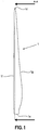
- Fig. 1 illustrates a rotor blade 1 of a wind turbine.
- the rotor blade 1 comprises a blade root 1e adapted for attachment of the rotor blade 1 to a rotor hub of the wind turbine rotor.
- the rotor blade 1 further comprises a blade tip 1d at the opposite end of the rotor blade 1 with respect to the blade root 1e.
- the rotor blade 1 also comprises a leading edge If on one side of the illustration and a trailing edge 1g on the opposite side, the leading and trailing edges If, 1g each running from the blade root 1e to the blade tip 1d.
- the trailing edge 1g has a distinctively bended shape with a distinct bulge within the first third of the blade length as seen from the blade root le.
- the rotor blade 1 will rotate about the rotor hub such that the leading edge If faces into the direction of rotation and the trailing edge 1g trails the movement of the rotor blade while the rotor blade tip 1d traces a circumference of the rotor.
- Fig. 2 is a view on the trailing edge 1g of the rotor blade 1 according to arrows A-A of Fig. 1 .
- the rotor blade 1 has a roughly wing-like shape with a cross section of the rotor blade having convex outlines between the trailing edge 1g and the leading edge If of the rotor blade 1.
- the blade root 1e has a polygonal or circular shape and the outlines of the rotor blade 1 extend mostly straight or convex there between.
- the rotor blade 1 contains a volume.
- the rotor blade 1 is comprised of blade halves 1a, 1b usually separated along the trailing edge 1g and the leading edge If.
- each blade half has at least a part of the trailing and the leading edges If, 1g of the rotor blade 1.
- the blade or blade half
- the blade halves 1a, 1b or segments are moulded from a mould material such as plastics reinforced with fibre glass or carbon fibre in a mould. During the moulding process, the mould material lines the mould and the mould surface determines the outer surface of the blade half 1a, 1b or segment.
- the rotor blade 1 is comprised of an upper blade half 1a and a lower blade half 1b.
- the upper and lower blade halves 1a, 1b are further separated into segments.
- the upper and lower blade halves 1a, 1b are attached to each other at a connection surface 1c running from the blade root 1e along the leading edge If to the blade tip 1d and via the trailing edge 1g back to the blade root 1e.
- upper blade half and a lower blade half refer to blade halves of the rotor blade previous to installation and during assembly of the rotor blade 1, when the upper blade half 1a is arranged on top of the lower blade half 1b for attachment thereto.
- a fixing device for fixating a blade segment of a rotor blade of a wind turbine to a mould in which the blade segment is manufactured, wherein the blade segment has a fixating extension comprises a first portion comprising a first abutment structure to selectively exert a clamping force on the fixating extension of the blade segment and a second portion for fixating the fixing device to the mould.
- the fixing device comprises at least one of a clamping force structure and a retaining structure.
- the clamping force structure comprises an aperture and a recess with a second abutment structure within the aperture, the aperture and the recess being arranged in one of the first and second portions, a cylinder portion with a threaded structure and a threaded abutment structure encircling the cylinder portion and engaging its threaded structure, and a third abutment structure arranged in the other one of the first and second portions.
- the aperture is adapted to receive the cylinder portion such that the cylinder portion protrudes the aperture along its cylinder axis
- the second abutment structure is adapted to engage and exert a force on the threaded abutment structure in a direction parallel to the cylinder axis
- the third abutment structure is adapted to receive a force from the cylinder portion in a direction towards the first abutment structure to exert the clamping force.
- the retaining structure comprises a lateral opening arranged in one of the first and second portions, and a retaining web arranged on the other one of the first and second portions, the retaining web being adapted for insertion into the lateral opening along an insertion direction, wherein the lateral opening is adapted to lock a movement of the retaining web in a direction perpendicular to the insertion direction and to the direction of the clamping force.
- the lateral opening extends from the aperture and allows the cylinder portion shifting into the aperture in a direction perpendicular to the cylinder axis.
- the retaining web extends in parallel to the cylinder axis.
- the first portion comprises a first abutment structure to exert the clamping force on the fixating extension of the blade segment, the first abutment structure being aligned to the cylinder axis of the cylinder portion.
- the one of the first and second portions comprising the cylinder portion further comprises a bracket having first and second terminals, the bracket holding the cylinder portion between the first and the second terminals, with the first and second terminals comprising the third abutment structure, such that the first and the second terminals are aligned to the cylinder axis, and connecting the cylinder portion to the one of the first and second portions.
- the retaining web extends between the first and second terminals, the retaining web being rigidly connected to the bracket and to the one of the first and second portions.
- the cylinder portion comprises a driving terminal, the driving terminal protruding one of the first and second terminals to rotationally adjust the cylinder portion.
- the first portion may comprise a handle attachment.
- the first portion (11) may comprise a handle attachment (11a).
- the cylinder portion is received permanently in one of the first and second portions.
- a mould for manufacturing a blade segment of a rotor blade for a wind turbine, the blade segment having a fixating extension comprises a hollow for forming the blade segment, a rim at an edge of the hollow, a flange extending perpendicularly from the rim and away from the hollow; and a fixing device according to any of the previous embodiments disposed on the flange, such that the first portion of the fixing device is arranged to selectively apply a clamping force against the rim and thereby clamping the fixating extension between the first portion and the rim.
- a method for manufacturing a rotor blade for a wind turbine in a mould comprises providing the first blade segment in the hollow of a mould according to the previous embodiment, such that the hollow faces upwards and the fixating portion overlies the rim, providing the first portion of the fixing device and clamping the fixating extension between the first portion and the rim of the mould, and providing the second blade segment in the hollow of a further mould, such that the hollow faces upwards.
- the method further comprises turning the mould such that the hollow with the first blade segment faces the second blade segment in the hollow of the further mould, arranging the first blade segment on the second blade segment, and unclamping the fixating extension between the first portion and the rim.
- clamping the fixating extension between the first portion and the rim comprises exerting a clamping force on the fixating extension towards the rim via a first abutment structure of the first portion.
- the clamping force is generated by rotating the cylinder portion such that the threaded abutment structure travels away from the rim and abuts against the second abutment structure within the recess.
- providing the first portion of the fixing device comprises shifting the cylinder portion through the lateral opening into the aperture of the second portion in a direction perpendicular to the cylinder axis, such that the threaded abutment structure is received in the recess portion.
- a rotor blade is manufactured according to at least one of the previous embodiments.
- Fig. 3 shows upper and lower moulds 20a, 20b for producing the blade halves 1a, 1b of the rotor blade 1.
- the upper and lower blade halves 1a, 1b are manufactured by moulding each of the upper and lower blade halves 1a, 1b in the upper and lower mould 20a, 20b, respectively.
- the upper and lower moulds 20a, 20b each comprise a respective hollow to receive the material for the blade halves 1a, 1b and to form and define the respective shape of the upper and lower blade halves 1a, 1b.
- fibre material is filled and/or laminated together with a polymer into the hollow of the mould 20a, 20b. Then, the material in the mould is cured.
- the upper blade half 1a is positioned on top of the lower blade half 1b for attachment of the upper and lower blade halves 1a, 1b to each other.
- the upper mould 20a which still contains the upper blade half 1a, is rotated and disposed on top of the lower blade half 1b which is still in the corresponding mould 20b, according to arrow 100.
- the moulds 20a, 20b of the upper and lower blade halves 1a, 1b, respectively, are provided with a first rim 21 at an edge of the hollow along the connection 1c at the leading edge If and a second rim 24 at an edge of the hollow along the connection 1c at the trailing edge 1g.
- an extension of the upper blade half 1a is arranged to overlie the first rim 21 at the leading edge If and the second rim 24 at the trailing edge 1g.
- the first and second rims 21, 24 form a surface facing away from the hollow of the mould 20a.
- the first and second rims 21, 24 border each other adjacent to a section of the upper mould 20a for the blade tip 1d.
- the upper mould 20a further comprises a first flange 22 adjacent to the first rim 21 at the leading edge of the rotor blade 1, with the first flange 22 extending away from the first rim 21 and from the hollow of the upper mould 20a.
- the first flange 22 extends perpendicularly to the first rim 21.
- the upper mould 20a further comprises a second flange 23 extending away from the second rim 24 and from the hollow of the upper mould 20a.
- the second flange 23 extends perpendicularly to the second rim 24.
- first and second rims 21, 24 are inclined towards the first and second flanges 22, 23, respectively, such that the first and second rims 21, 24 and the first and second flanges 22, 23, respectively, form an acute angle.
- first and second flanges 22 and 23 are coplanar with respect to each other.
- the first and second flanges 22, 23 are adapted to receive a fixing device as introduced further below, the fixing device fixing the upper blade half 1a to the upper mould 20a. To this end, the fixing device is attached to the first and second flanges 22, 23 and presses the extension of the upper blade half 1a against the first and second rims 21, 24.
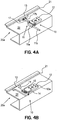
- Fig. 4A shows a perspective view of the first flange 22 and the first rim 21 with an inventive fixing device 10.
- the fixing device 10 comprises a first portion 11 for clamping the extension of the blade half 1a against the first rim 21 of the mould 20a.
- the fixing device 10 further comprises a second portion 12 for rigidly attaching the fixing device 10 to the first flange 22 of the mould 20a.
- the first portion 11 comprises a first abutment structure 13 adapted to exert a clamping force on the extension of the blade half such that the extension of the blade half is clamped between the first abutment structure 13 and the first rim 21.
- the second portion 12 is adapted to support the first portion 11 when exerting the clamping force on the extension of the blade half.
- the first portion 11 is held in place by clamping between the second portion 12 and the first rim 21. If the clamping force is released, the first portion 11 may be removed from the second portion 12 and the first flange 22.
- the first portion 11 comprises a handle attachment 11a to attach a handle 11b for removing the first portion 11 by hand.
- the handle attachment is adapted to be engaged by a placement and removing device (not shown).
- the first portion 11 further comprises a shaft 17 to transfer the exerted force from the second portion 12 to the first abutment structure 13.
- the shaft 17 further comprises attachment members 17b to releasably attach the abutment structure 13 to the shaft 17.
- the attachment members 17b are screws and are adapted to be released by unscrewing. This way, the first abutment structure 13 may be exchanged to adapt to a different shape of the first rim 21 or to provide variable abutment surfaces to adapt to different fibre reinforced polymers.
- Fig. 4B shows the fixing device 10 with the first portion 11 detached from the second portion 12. Since the first portion is disengaged from the second portion 12 a clamping drive 15 of the first portion 11 is visible. Also, since the clamping drive 15 of the first portion 11 is disengaged, an aperture 14 is visible in the second portion 12. After disengagement, the aperture 14 in the second portion 12 faces the clamping drive 15 in the first portion 11. Likewise, immediately before engaging the clamping drive 15 of the first portion 11 and the aperture 14 of the second portion 12, the clamping drive 15 and the aperture 14 face each other.
- the first abutment structure 13 of the first portion 11 exerts no force on the first rim 21 and the extension of the upper blade half 1a may be disposed at or removed from the first rim 21.
- the disengaged first portion 11 can be removed by the placement and removing device or by hand.
- the first abutment structure 13 is formed integrally with the first portion 11. This allows simplifying manufacturing of the first portion 11 since no accommodation for attachment members must be provided. Such configuration is particularly suitable if characteristics of the first abutment structure 13 suit a large number of rotor blade materials and/or shapes as well as materials and/or shapes of the first rim 21.
- the second portion 12 of the fixing device 10 further comprises at least one attachment member 12a, such as at least one screw, for attaching the second portion 12 stationary to the first flange 22.
- Fig. 5A shows the fixing device 10 similar to the fixing device 10 of Figs. 4A and 4B in more detail.
- the fixing device 10 comprises the first portion 11 and the second portion 12.
- the first portion 11 comprises a bracket 19 holding the clamping drive 15 in a recess as explained further below.
- the first portion 11 comprises an access aperture 17a in the shaft 17 between the first abutment structure 13 and the bracket 19.
- the access aperture 17a is adapted to dispose an attachment member 17b for attachment of the first abutment structure 13 to the shaft 17.
- the access aperture 17a is arranged on a side of the shaft 17 or centrally with portions of the shaft 17 connecting the bracket 19 and the first abutment structure 13 on two sides of the access aperture.
- a section of the second portion 12 containing the aperture 14 fits snugly into the recess of the bracket 19, however, allows certain movement of the first portion 11 with respect to the second portion 12 in the direction of the clamping force, when the aperture section of the second portion 12 engages the clamping drive 15 in the recess of the bracket 19.
- a driving terminal 15c of the clamping drive 15 protrudes a side of the first portion 11 facing away from the first abutment structure 13.
- the driving terminal 15c is accessible while the rest of the clamping drive 15 is arranged in the aperture 14 and is used to rotationally adjust the cylinder portion 15a of the clamping drive 15 and thereby the clamping force of the clamping drive.
- the second portion 12 comprises an alignment spigot 12b adapted to align the upper mould 20a on the lower mould 20b when closing the moulds 20a, 20b.
- the respective other mould has a hole that goes together with the alignment spigot 12b.
- the second portion may instead have a measurement member to indicate alignment, proximity, a pressure of the first mould 20a on the second mould 20b or any other parameter indicative of a relation of the upper mould 20a and the lower mould 20b to each other.
- Fig. 5B shows the fixing device 10 of Fig. 4B in more detail.
- the first abutment structure 13 is formed integrally with the first portion 11, such that the first abutment structure 13, the shaft 17 and the bracket 19 form an integral structure.
- the bracket 19 has a first terminal 19b and a second terminal 19c holding the clamping drive 15 there between. At least one of the first and second terminals 19b, 19c comprises a third abutment structure receiving the adjusted clamping force from the clamping drive 15.
- the abutment structure 13, the shaft 17 and the clamping drive 15 are aligned to each other.
- first abutment structure 13 and the shaft 17 are adapted to be aligned to a clamping force which is generated by the clamping drive 15.
- the bracket 19 holds the clamping drive 15 in position and thereby orients the clamping force, particularly by the position of the first and second terminals 19b, 19c with respect to each other, which position determines roughly the direction of the clamping force F1.
- the first and second terminals 19b, 19c are arranged such that the second terminal 19c is arranged between the first terminal 19b and the first abutment structure 13.
- the clamping drive 15 comprises a cylinder portion 15a and a threaded abutment structure 15b such as a nut.
- This cylinder portion 15a has a threaded structure at its circumference and the threaded abutment structure 15b has an inner threading engaging the threaded structure of the cylinder portion 15a. Accordingly, by rotation of the cylinder portion 15a the threaded abutment structure 15b can move along the cylinder portion or can be forced in a direction along the cylinder portion 15a.
- the third abutment structure is adapted to lock the cylinder portion 15a against displacement towards the first abutment structure 13. Thereby the third abutment structure is adapted to receive the adjusted clamping force.
- the third abutment structure is formed in at least one of the first and second terminals 19b, 19c as a surface against which the cylinder portion 15a abuts along its cylinder axis.
- the second terminal 19c forms an abutting surface as the third abutment structure and a tip portion of the cylinder portion 15a is adapted to press against the abutting surface.
- the abutting surface is formed at the bottom of a blind hole 19d in the second terminal 19c to receive the tip portion and to stabilise the tip portion on the abutting surface, wherein the side walls of the blind hole prevent the tip portion from a sideways displacement.
- the cylinder portion 15a has a constriction and the first terminal 19b is formed to engage the constriction.
- the first terminal 19b receives the cylinder portion 15a in a hole with a similar diameter as the cylinder portion 15a.
- the clamping drive 15 comprises a screw head with a larger diameter than the cylinder portion 15a.
- the screw head is arranged together with the driving terminal 15c. The clamping drive 15 is adapted to abut with the screw head on the edge of the hole in the first terminal 19b, such that the edge of the hole forms the third abutment structure.
- the clamping drive 15 comprises the driving terminal 15c for rotating the cylinder portion 15a.
- the driving terminal 15c has an engagement structure for a screw driver or any device adapted to drive the cylinder portion rotationally in order to shift the threaded abutment structure 15b along the cylinder portion and/or to force the threaded abutment structure 15b along the cylinder portion and thus, generate the clamping force F1.
- the clamping drive 15 further comprises a fastening retainer such as a retaining ring or a circlip 15d to keep the cylinder portion between first and second bracket terminals 19b, 19c.
- the second portion 12 comprises an aperture 14, which is adapted to receive the clamping drive 15 such that the clamping drive 15 protrudes the aperture 14.
- the aperture 14 is arranged at one side of the second portion 12.
- the second portion 12 is arranged on the first flange 22 of the upper mould 20a such that the aperture 14 extends through the second portion 12 towards the first rim 21 of the first mould 20a.
- the aperture 14 has a lateral opening 18 such that the aperture 14 has a U-shaped cross sectional profile with two flanks opposing each other and opens to the one side of the second portion 12.
- the aperture 14 is adapted to receive the cylinder portion 15a of the clamping drive 15 through the lateral opening such that the cylinder portion does not need to be shifted through the aperture along its length.
- the aperture 14 further comprises a recess portion 16 such that in a section of the aperture a distance between its flanks is increased.
- a second abutment structure 16a is provided, adapted to abut the threaded abutment structure 15b of the clamping drive 15 in a direction towards the first rim 21 of the mould 20a.
- the second abutment structure 16a faces in the direction of the first rim 21.
- the aperture 14 is dimensioned to receive the cylinder portion 15a of the clamping drive 15 and the recess 16 is adapted to receive the threaded abutment structure 15b.
- the threaded abutment structure 15b has an outer diameter which is larger than the distance between the flanks of the remainder of the aperture 14 and therefore does not fit into the remainder of the aperture 14 at least when the threaded abutment structure 15b engages the threaded structure of the cylinder portion 15a.
- the recess 16 also extends through the lateral opening 18 such that the threaded abutment structure can be pushed through the recess 16 of the lateral opening 18.
- the bracket 19 further comprises a retaining web 19a extending between the first and second terminals 19b, 19c of the bracket 19.
- the retaining web 19a fits snugly into the lateral opening 18 of the aperture 14 of the second portion 12.
- the retaining web 19a is adapted to take up forces perpendicular to a direction of the clamping force F1, particularly in a normal direction from the first flange 22.
- the lateral opening and the aperture are separated by a wall (not shown).
- the cylinder portion and the retaining web are arranged permanently in the aperture and the lateral opening.
- the second portion 12 further comprises a receptacle 12c for receiving the spigot 12b or a corresponding structure at the flange of the opposing lower mould 20b.
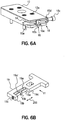
- Fig. 6A shows the clamping drive 15 received in the aperture 14 of the second portion 12. While the second portion 12 is attached to the first flange 22 by the attachment member 12a, the clamping drive is shifted into the aperture 14 perpendicularly to the cylinder axis of the cylinder portion 15a. At the same time, the cylinder portion 15a reaches through the threaded abutment structure 15b and the threaded structure of the cylinder portion 15a engages the threading of the threaded abutment structure 15b.
- the aperture 14 has a U-shaped cross section with flanks at both sides. The recess 16 is formed by recess portions at locations on the inner surfaces of the flanks facing each other.
- the recess portions reach through the lateral opening 18 of the aperture such that the threaded abutment structure 15b can be pushed through the lateral opening 18 into the recess 16 and can be pulled out again in the reverse direction.
- the second abutment structure 16a is arranged at the transition from the recess portions to the remainder of the flanks of the aperture 14. When the second portion 12 is attached to the first flange 22, the second abutment structure 16a faces the first rim 21 of the mould 20a and abuts the clamping drive to exert a force towards the first rim 21.
- the driving terminal 15c is adapted to receive a corresponding rotational device or tool (not shown), such as a screw driver, and is adapted to rotate according to the action of the corresponding tool.
- the cylinder portion 15a rotates together with the rotation of the driving terminal 15c.
- the driving terminal 15c has a female hexagonal socket head to receive the rotational device.
- Fig. 6A further shows the fastening retainer 15d which is arranged on the cylinder portion 15a to prevent the cylinder portion 15a from slipping out of the bracket 19 (not shown in Fig. 6A ).
- Fig. 6B shows the first portion 11.
- the retaining web 19a within the bracket 19 extends between first and second terminals 19b, 19c of the bracket 19 and in parallel to the cylinder portion 15a of the clamp drive.
- the retaining web will effectively take up bending moments caused by forces in the direction transversal to the clamping force such that the clamp drive 15 and its cylinder portion 15a do not have to take up such forces.
- Such forces may be particularly due to a gravity force when the upper mould 20a is turned on top of the lower mould 20b is will have a component in a normal direction of a surface of the first flange 22.
- the retaining web 19a has a shallow recess 19a' allowing free travel of the threaded abutment structure along the retaining web 19a without obstructing its way of travel.
- the retaining web 19a in the depicted embodiment reaches closely to the cylinder portion 15a and thereby provides a large abutment surface for the flank of the aperture 14 in the area of the lateral opening 18, i.e. for the flank of the lateral opening 18.
- the retaining web 19a takes up a force of gravity on the first portion 11.
- the retaining web 19a either abuts against one flank of the lateral opening 18 or cants between both flanks of the lateral opening 18.
- the retaining web is arranged at the second portion at the position of the lateral opening.
- the lateral opening is arranged on the first portion.
- the clamping drive 15 in above embodiments has been shown and explained to be arranged on the first portion 11, which is the portion removable for allowing disposal and removal of the upper blade half 1a and the blade 1, respectively, to and from the mould 20a, 20b.
- the clamping drive 15 together with the cylinder portion 15a, the threaded abutment structure 15b, the driving terminal 15c and the fastening retainer 15d is arranged in the second portion, which is the stationary portion fixed to the first flange 22 of the upper mould 20a.
- the aperture 14 providing the second abutment structure 16a and the recess 16 is arranged on the removable first portion.
- Fig. 7 shows a further embodiment of the fixing device 10.
- the lateral opening and the aperture are separated by a wall there between.
- the cylinder portion 15a is arranged in the aperture.
- the second terminal 19c comprises a third abutment structure and the cylinder portion 15a abuts against the third abutment structure of the second terminal 19c of the first portion 11.
- the second terminal is 19c is provided with a hollow to receive a tip portion 15e of the cylinder portion 15a.
- the third abutment structure is adapted to receive a force from the cylinder portion in a direction towards the first abutment structure 13 to exert a clamping force in a direction to the first abutment structure 13 and to the first rim 21.
- the cylinder portion 15a When the threaded abutment structure 15b is released from the second abutment structure 16a, the cylinder portion 15a is withdrawable from the second terminal 19c and releases the first portion 11 from engagement with the second portion 12 and with the first rim 21.
- the cylinder portion 15a is held within the aperture and the second portion 12 during the operation lifetime, since the threaded abutment structure 15b is permanently received in the recess 16 and the cylinder portion 15a is permanently threaded through the threaded abutment structure 15b, such that the cylinder portion is not released from the second portion during a multitude of cycles of use.
- the cylinder portion 15a is threaded into the threaded abutment structure each time the first portion 11 shall be clamped against the first rim 21.
- the first portion provides the retaining web 19a in a cantilever-type configuration, i.e. the retaining web 19a is supported at the first portion 11 at only one end, which is the end closer to the first abutment structure 13.
- the retaining web 19a extends in parallel to the cylinder portion 15a when the first portion 11 is clamped to the first rim 21.
- the retaining web 19a is adapted to be inserted into the lateral opening either in a direction towards the recess 16 or in a direction parallel to the cylinder axis, i.e. the retaining web can be inserted into the lateral opening from the side facing the first rim 21.
- the first portion does not have a retaining web and only serves to clamp an extension of an upper blade half to the first rim 21, particularly in arrangements where the first rim 21 and the first flange 22 form an acute angle such that less retaining force is required.
- the upper mould 20a is arranged with the upper blade half 1a in the hollow facing upwards.
- the extension of the upper blade half 1a is arranged to overly the first rim 21, such that the outermost portion of the extension faces to the first flange 22, where the stationary second portion 12 is attached.
- the first portion 11 with its first abutment structure 13 is disposed to retain the extension of the upper blade half 1a between the first rim 21 and the first abutment structure 13.
- the cylinder portion 15a of the clamp drive 15 is shifted through the lateral opening 18 into the aperture 14 such that the threaded abutment structure 15b is received in the recess portion 16.
- the driving terminal 15c is rotated such that the threaded abutment structure 15b travels away from the first rim 21 and abuts against the second abutment structure 16a within the recess 16.
- the clamping force F1 is built up and retains the extension of the upper blade half 1a between the first rim 21 and the first abutment structure 13.
- the fixing device 10 prevents any displacement of the upper blade half 1a within the upper mould 20a or even that the upper blade half 1a falls out of the upper mould 20a.
- the clamping force F1 When the upper mould 20a is above the lower mould 20b, the clamping force F1 provides high friction between the extension of the upper blade half 1a with respect to both, the first rim 21 and the first abutment structure 13.
- the clamping force F1 from the fixing device 10 thereby counteracts the force of gravity of the upper blade half 1a.
- the clamping force F1 also acts on the first portion 11 and presses the first portion 11 against the first flange 22. Then, the weight of the upper blade half 1a is particularly held by the first rim 21.
- the clamping force F1 holds the extension to the rim 21 and to the first portion 11, which first portion 11 is held against gravity by the retaining web 19a in the lateral opening 18 of the second portion 12.
- the driving terminal 15c of the clamp drive 15 may be rotated in reverse, such that the threaded abutment structure 15b travels back towards the first rim 21 and thereby decreases the clamping force F1. The first portion 11 is then removed.
- the extension of the upper blade half 1a is pliable, such that the extension can slip from the first and second rims 21, 24 for removal.
Landscapes
- Engineering & Computer Science (AREA)
- Mechanical Engineering (AREA)
- Chemical & Material Sciences (AREA)
- Composite Materials (AREA)
- Wind Motors (AREA)
Applications Claiming Priority (2)
| Application Number | Priority Date | Filing Date | Title |
|---|---|---|---|
| DKPA201370818 | 2013-12-23 | ||
| PCT/DK2014/050430 WO2015096839A1 (en) | 2013-12-23 | 2014-12-12 | Fixing device for fixating a segment of a wind turbine blade to a mould |
Publications (2)
| Publication Number | Publication Date |
|---|---|
| EP3086925A1 EP3086925A1 (en) | 2016-11-02 |
| EP3086925B1 true EP3086925B1 (en) | 2021-03-24 |
Family
ID=52272795
Family Applications (1)
| Application Number | Title | Priority Date | Filing Date |
|---|---|---|---|
| EP14821059.4A Active EP3086925B1 (en) | 2013-12-23 | 2014-12-12 | Fixing device for fixating a segment of a wind turbine blade to a mould |
Country Status (6)
| Country | Link |
|---|---|
| US (1) | US10569485B2 (da) |
| EP (1) | EP3086925B1 (da) |
| CN (1) | CN106029348B (da) |
| DK (1) | DK3086925T3 (da) |
| ES (1) | ES2864902T3 (da) |
| WO (1) | WO2015096839A1 (da) |
Families Citing this family (1)
| Publication number | Priority date | Publication date | Assignee | Title |
|---|---|---|---|---|
| US10919247B2 (en) * | 2016-06-15 | 2021-02-16 | Vestas Wind Systems A/S | Method and apparatus for making a shear web |
Family Cites Families (7)
| Publication number | Priority date | Publication date | Assignee | Title |
|---|---|---|---|---|
| US4251065A (en) * | 1980-01-24 | 1981-02-17 | Mcdougal Thomas F | Quick set hydraulic vise |
| DE8910548U1 (de) * | 1988-10-31 | 1989-11-02 | Deutsche Star Gmbh, 8720 Schweinfurt | Linearführungs- und Antriebseinheit |
| US6092797A (en) * | 1999-03-10 | 2000-07-25 | You; Yen-Jen | Quick clamping type vice |
| ATE364494T1 (de) | 2005-02-24 | 2007-07-15 | Vestas Wind Sys As | Verfahren zur herstellung eines windturbinenblatts, eine produktionsanlage von windturbinenblättern und verwendung hiervon |
| DK2308670T3 (da) * | 2009-10-12 | 2014-02-10 | Vestas Wind Sys As | Fremgangsmåde til at fremstille en vindmøllevinge i en form omfattende en fikseringsindretning |
| US9010205B2 (en) * | 2011-01-20 | 2015-04-21 | Pacific Bearing Company | Linear slide having integral carriage and nut assembly |
| FR2985927B1 (fr) * | 2012-01-25 | 2014-12-26 | Snecma | Outillage de fabrication d'une pale d'helice, comprenant un patin de serrage |
-
2014
- 2014-12-12 DK DK14821059.4T patent/DK3086925T3/da active
- 2014-12-12 CN CN201480076177.8A patent/CN106029348B/zh active Active
- 2014-12-12 ES ES14821059T patent/ES2864902T3/es active Active
- 2014-12-12 EP EP14821059.4A patent/EP3086925B1/en active Active
- 2014-12-12 WO PCT/DK2014/050430 patent/WO2015096839A1/en not_active Ceased
- 2014-12-12 US US15/107,690 patent/US10569485B2/en active Active
Non-Patent Citations (1)
| Title |
|---|
| None * |
Also Published As
| Publication number | Publication date |
|---|---|
| DK3086925T3 (da) | 2021-04-19 |
| CN106029348A (zh) | 2016-10-12 |
| ES2864902T3 (es) | 2021-10-14 |
| US20160318263A1 (en) | 2016-11-03 |
| US10569485B2 (en) | 2020-02-25 |
| EP3086925A1 (en) | 2016-11-02 |
| CN106029348B (zh) | 2018-01-05 |
| WO2015096839A1 (en) | 2015-07-02 |
Similar Documents
| Publication | Publication Date | Title |
|---|---|---|
| US7950887B2 (en) | Threaded fastener with retainer and method of making such fastener | |
| US6467990B1 (en) | Arrangement for securing a component | |
| EP3086925B1 (en) | Fixing device for fixating a segment of a wind turbine blade to a mould | |
| DE102018117667A1 (de) | Spannvorrichtung | |
| US7941933B2 (en) | Clamping device | |
| US20080240849A1 (en) | Non-marring shaft collar | |
| CN211193043U (zh) | 一种十字轴式万向节钻孔用夹具 | |
| BRPI0615361A2 (pt) | dispositivo e método para montar objetos em uma parede de veìculo | |
| KR101477274B1 (ko) | 겹쳐진 플레이트 및/또는 부품의 작업편 조립용 마운팅/조립 요소 | |
| WO2011095620A1 (en) | Arrangement of a toothed belt wheel | |
| CN111729976B (zh) | 一种楔形耐张线夹冲压装置 | |
| KR101654939B1 (ko) | 초지기 내에 닥터 블레이드 조립체의 피봇 장착용 장치 및 방법 | |
| CN2409017Y (zh) | 轴承安装器 | |
| CN203532672U (zh) | 锁紧型同步带轮 | |
| CN216097605U (zh) | 花键轴内孔加工夹具 | |
| CN217552177U (zh) | 一种长条型结构异型件 | |
| CN112497127A (zh) | 一种5kw发电机皮带轮安装专用工具及安装方法 | |
| CN203463459U (zh) | 一种螺母 | |
| CN110043632B (zh) | 一种齿轮轴结构 | |
| KR200270232Y1 (ko) | 베어링 공구 | |
| CN216895300U (zh) | 一种可拆卸的防松螺钉组件 | |
| CN219503838U (zh) | 一种金属型材切割锯 | |
| CN222351077U (zh) | 一种球型固定件 | |
| CN217413825U (zh) | 一种防跑枪的螺丝刀刀头及与其配合的螺丝钉 | |
| CN213684885U (zh) | 一种实现拉力调节的螺栓 |
Legal Events
| Date | Code | Title | Description |
|---|---|---|---|
| PUAI | Public reference made under article 153(3) epc to a published international application that has entered the european phase |
Free format text: ORIGINAL CODE: 0009012 |
|
| 17P | Request for examination filed |
Effective date: 20160623 |
|
| AK | Designated contracting states |
Kind code of ref document: A1 Designated state(s): AL AT BE BG CH CY CZ DE DK EE ES FI FR GB GR HR HU IE IS IT LI LT LU LV MC MK MT NL NO PL PT RO RS SE SI SK SM TR |
|
| AX | Request for extension of the european patent |
Extension state: BA ME |
|
| DAX | Request for extension of the european patent (deleted) | ||
| GRAP | Despatch of communication of intention to grant a patent |
Free format text: ORIGINAL CODE: EPIDOSNIGR1 |
|
| STAA | Information on the status of an ep patent application or granted ep patent |
Free format text: STATUS: GRANT OF PATENT IS INTENDED |
|
| RIC1 | Information provided on ipc code assigned before grant |
Ipc: B29L 31/08 20060101ALI20200422BHEP Ipc: B25B 5/10 20060101ALI20200422BHEP Ipc: B29C 70/54 20060101AFI20200422BHEP Ipc: B29C 33/00 20060101ALI20200422BHEP Ipc: B29C 33/26 20060101ALI20200422BHEP Ipc: B25B 5/00 20060101ALI20200422BHEP |
|
| INTG | Intention to grant announced |
Effective date: 20200518 |
|
| GRAJ | Information related to disapproval of communication of intention to grant by the applicant or resumption of examination proceedings by the epo deleted |
Free format text: ORIGINAL CODE: EPIDOSDIGR1 |
|
| STAA | Information on the status of an ep patent application or granted ep patent |
Free format text: STATUS: REQUEST FOR EXAMINATION WAS MADE |
|
| GRAP | Despatch of communication of intention to grant a patent |
Free format text: ORIGINAL CODE: EPIDOSNIGR1 |
|
| STAA | Information on the status of an ep patent application or granted ep patent |
Free format text: STATUS: GRANT OF PATENT IS INTENDED |
|
| INTC | Intention to grant announced (deleted) | ||
| INTG | Intention to grant announced |
Effective date: 20201014 |
|
| GRAS | Grant fee paid |
Free format text: ORIGINAL CODE: EPIDOSNIGR3 |
|
| GRAA | (expected) grant |
Free format text: ORIGINAL CODE: 0009210 |
|
| STAA | Information on the status of an ep patent application or granted ep patent |
Free format text: STATUS: THE PATENT HAS BEEN GRANTED |
|
| AK | Designated contracting states |
Kind code of ref document: B1 Designated state(s): AL AT BE BG CH CY CZ DE DK EE ES FI FR GB GR HR HU IE IS IT LI LT LU LV MC MK MT NL NO PL PT RO RS SE SI SK SM TR |
|
| REG | Reference to a national code |
Ref country code: GB Ref legal event code: FG4D |
|
| REG | Reference to a national code |
Ref country code: CH Ref legal event code: EP |
|
| REG | Reference to a national code |
Ref country code: DE Ref legal event code: R096 Ref document number: 602014076000 Country of ref document: DE |
|
| REG | Reference to a national code |
Ref country code: IE Ref legal event code: FG4D |
|
| REG | Reference to a national code |
Ref country code: AT Ref legal event code: REF Ref document number: 1374058 Country of ref document: AT Kind code of ref document: T Effective date: 20210415 |
|
| REG | Reference to a national code |
Ref country code: DK Ref legal event code: T3 Effective date: 20210415 |
|
| REG | Reference to a national code |
Ref country code: LT Ref legal event code: MG9D |
|
| PG25 | Lapsed in a contracting state [announced via postgrant information from national office to epo] |
Ref country code: GR Free format text: LAPSE BECAUSE OF FAILURE TO SUBMIT A TRANSLATION OF THE DESCRIPTION OR TO PAY THE FEE WITHIN THE PRESCRIBED TIME-LIMIT Effective date: 20210625 Ref country code: HR Free format text: LAPSE BECAUSE OF FAILURE TO SUBMIT A TRANSLATION OF THE DESCRIPTION OR TO PAY THE FEE WITHIN THE PRESCRIBED TIME-LIMIT Effective date: 20210324 Ref country code: FI Free format text: LAPSE BECAUSE OF FAILURE TO SUBMIT A TRANSLATION OF THE DESCRIPTION OR TO PAY THE FEE WITHIN THE PRESCRIBED TIME-LIMIT Effective date: 20210324 Ref country code: BG Free format text: LAPSE BECAUSE OF FAILURE TO SUBMIT A TRANSLATION OF THE DESCRIPTION OR TO PAY THE FEE WITHIN THE PRESCRIBED TIME-LIMIT Effective date: 20210624 Ref country code: NO Free format text: LAPSE BECAUSE OF FAILURE TO SUBMIT A TRANSLATION OF THE DESCRIPTION OR TO PAY THE FEE WITHIN THE PRESCRIBED TIME-LIMIT Effective date: 20210624 |
|
| PG25 | Lapsed in a contracting state [announced via postgrant information from national office to epo] |
Ref country code: LV Free format text: LAPSE BECAUSE OF FAILURE TO SUBMIT A TRANSLATION OF THE DESCRIPTION OR TO PAY THE FEE WITHIN THE PRESCRIBED TIME-LIMIT Effective date: 20210324 Ref country code: RS Free format text: LAPSE BECAUSE OF FAILURE TO SUBMIT A TRANSLATION OF THE DESCRIPTION OR TO PAY THE FEE WITHIN THE PRESCRIBED TIME-LIMIT Effective date: 20210324 Ref country code: SE Free format text: LAPSE BECAUSE OF FAILURE TO SUBMIT A TRANSLATION OF THE DESCRIPTION OR TO PAY THE FEE WITHIN THE PRESCRIBED TIME-LIMIT Effective date: 20210324 |
|
| REG | Reference to a national code |
Ref country code: NL Ref legal event code: MP Effective date: 20210324 |
|
| REG | Reference to a national code |
Ref country code: AT Ref legal event code: MK05 Ref document number: 1374058 Country of ref document: AT Kind code of ref document: T Effective date: 20210324 |
|
| PG25 | Lapsed in a contracting state [announced via postgrant information from national office to epo] |
Ref country code: NL Free format text: LAPSE BECAUSE OF FAILURE TO SUBMIT A TRANSLATION OF THE DESCRIPTION OR TO PAY THE FEE WITHIN THE PRESCRIBED TIME-LIMIT Effective date: 20210324 |
|
| REG | Reference to a national code |
Ref country code: ES Ref legal event code: FG2A Ref document number: 2864902 Country of ref document: ES Kind code of ref document: T3 Effective date: 20211014 |
|
| PG25 | Lapsed in a contracting state [announced via postgrant information from national office to epo] |
Ref country code: AT Free format text: LAPSE BECAUSE OF FAILURE TO SUBMIT A TRANSLATION OF THE DESCRIPTION OR TO PAY THE FEE WITHIN THE PRESCRIBED TIME-LIMIT Effective date: 20210324 Ref country code: LT Free format text: LAPSE BECAUSE OF FAILURE TO SUBMIT A TRANSLATION OF THE DESCRIPTION OR TO PAY THE FEE WITHIN THE PRESCRIBED TIME-LIMIT Effective date: 20210324 Ref country code: CZ Free format text: LAPSE BECAUSE OF FAILURE TO SUBMIT A TRANSLATION OF THE DESCRIPTION OR TO PAY THE FEE WITHIN THE PRESCRIBED TIME-LIMIT Effective date: 20210324 Ref country code: EE Free format text: LAPSE BECAUSE OF FAILURE TO SUBMIT A TRANSLATION OF THE DESCRIPTION OR TO PAY THE FEE WITHIN THE PRESCRIBED TIME-LIMIT Effective date: 20210324 Ref country code: SM Free format text: LAPSE BECAUSE OF FAILURE TO SUBMIT A TRANSLATION OF THE DESCRIPTION OR TO PAY THE FEE WITHIN THE PRESCRIBED TIME-LIMIT Effective date: 20210324 |
|
| PG25 | Lapsed in a contracting state [announced via postgrant information from national office to epo] |
Ref country code: IS Free format text: LAPSE BECAUSE OF FAILURE TO SUBMIT A TRANSLATION OF THE DESCRIPTION OR TO PAY THE FEE WITHIN THE PRESCRIBED TIME-LIMIT Effective date: 20210724 Ref country code: SK Free format text: LAPSE BECAUSE OF FAILURE TO SUBMIT A TRANSLATION OF THE DESCRIPTION OR TO PAY THE FEE WITHIN THE PRESCRIBED TIME-LIMIT Effective date: 20210324 Ref country code: RO Free format text: LAPSE BECAUSE OF FAILURE TO SUBMIT A TRANSLATION OF THE DESCRIPTION OR TO PAY THE FEE WITHIN THE PRESCRIBED TIME-LIMIT Effective date: 20210324 Ref country code: PL Free format text: LAPSE BECAUSE OF FAILURE TO SUBMIT A TRANSLATION OF THE DESCRIPTION OR TO PAY THE FEE WITHIN THE PRESCRIBED TIME-LIMIT Effective date: 20210324 Ref country code: PT Free format text: LAPSE BECAUSE OF FAILURE TO SUBMIT A TRANSLATION OF THE DESCRIPTION OR TO PAY THE FEE WITHIN THE PRESCRIBED TIME-LIMIT Effective date: 20210726 |
|
| REG | Reference to a national code |
Ref country code: DE Ref legal event code: R097 Ref document number: 602014076000 Country of ref document: DE |
|
| PG25 | Lapsed in a contracting state [announced via postgrant information from national office to epo] |
Ref country code: AL Free format text: LAPSE BECAUSE OF FAILURE TO SUBMIT A TRANSLATION OF THE DESCRIPTION OR TO PAY THE FEE WITHIN THE PRESCRIBED TIME-LIMIT Effective date: 20210324 |
|
| PLBE | No opposition filed within time limit |
Free format text: ORIGINAL CODE: 0009261 |
|
| STAA | Information on the status of an ep patent application or granted ep patent |
Free format text: STATUS: NO OPPOSITION FILED WITHIN TIME LIMIT |
|
| PG25 | Lapsed in a contracting state [announced via postgrant information from national office to epo] |
Ref country code: SI Free format text: LAPSE BECAUSE OF FAILURE TO SUBMIT A TRANSLATION OF THE DESCRIPTION OR TO PAY THE FEE WITHIN THE PRESCRIBED TIME-LIMIT Effective date: 20210324 |
|
| 26N | No opposition filed |
Effective date: 20220104 |
|
| PG25 | Lapsed in a contracting state [announced via postgrant information from national office to epo] |
Ref country code: IS Free format text: LAPSE BECAUSE OF FAILURE TO SUBMIT A TRANSLATION OF THE DESCRIPTION OR TO PAY THE FEE WITHIN THE PRESCRIBED TIME-LIMIT Effective date: 20210724 |
|
| PG25 | Lapsed in a contracting state [announced via postgrant information from national office to epo] |
Ref country code: MC Free format text: LAPSE BECAUSE OF FAILURE TO SUBMIT A TRANSLATION OF THE DESCRIPTION OR TO PAY THE FEE WITHIN THE PRESCRIBED TIME-LIMIT Effective date: 20210324 |
|
| REG | Reference to a national code |
Ref country code: CH Ref legal event code: PL |
|
| REG | Reference to a national code |
Ref country code: BE Ref legal event code: MM Effective date: 20211231 |
|
| PG25 | Lapsed in a contracting state [announced via postgrant information from national office to epo] |
Ref country code: LU Free format text: LAPSE BECAUSE OF NON-PAYMENT OF DUE FEES Effective date: 20211212 Ref country code: IE Free format text: LAPSE BECAUSE OF NON-PAYMENT OF DUE FEES Effective date: 20211212 |
|
| PG25 | Lapsed in a contracting state [announced via postgrant information from national office to epo] |
Ref country code: FR Free format text: LAPSE BECAUSE OF NON-PAYMENT OF DUE FEES Effective date: 20211231 Ref country code: BE Free format text: LAPSE BECAUSE OF NON-PAYMENT OF DUE FEES Effective date: 20211231 |
|
| PG25 | Lapsed in a contracting state [announced via postgrant information from national office to epo] |
Ref country code: LI Free format text: LAPSE BECAUSE OF NON-PAYMENT OF DUE FEES Effective date: 20211231 Ref country code: CH Free format text: LAPSE BECAUSE OF NON-PAYMENT OF DUE FEES Effective date: 20211231 |
|
| PG25 | Lapsed in a contracting state [announced via postgrant information from national office to epo] |
Ref country code: IT Free format text: LAPSE BECAUSE OF FAILURE TO SUBMIT A TRANSLATION OF THE DESCRIPTION OR TO PAY THE FEE WITHIN THE PRESCRIBED TIME-LIMIT Effective date: 20210324 |
|
| PG25 | Lapsed in a contracting state [announced via postgrant information from national office to epo] |
Ref country code: HU Free format text: LAPSE BECAUSE OF FAILURE TO SUBMIT A TRANSLATION OF THE DESCRIPTION OR TO PAY THE FEE WITHIN THE PRESCRIBED TIME-LIMIT; INVALID AB INITIO Effective date: 20141212 |
|
| P01 | Opt-out of the competence of the unified patent court (upc) registered |
Effective date: 20230521 |
|
| PG25 | Lapsed in a contracting state [announced via postgrant information from national office to epo] |
Ref country code: CY Free format text: LAPSE BECAUSE OF FAILURE TO SUBMIT A TRANSLATION OF THE DESCRIPTION OR TO PAY THE FEE WITHIN THE PRESCRIBED TIME-LIMIT Effective date: 20210324 |
|
| PG25 | Lapsed in a contracting state [announced via postgrant information from national office to epo] |
Ref country code: MK Free format text: LAPSE BECAUSE OF FAILURE TO SUBMIT A TRANSLATION OF THE DESCRIPTION OR TO PAY THE FEE WITHIN THE PRESCRIBED TIME-LIMIT Effective date: 20210324 |
|
| PG25 | Lapsed in a contracting state [announced via postgrant information from national office to epo] |
Ref country code: MT Free format text: LAPSE BECAUSE OF FAILURE TO SUBMIT A TRANSLATION OF THE DESCRIPTION OR TO PAY THE FEE WITHIN THE PRESCRIBED TIME-LIMIT Effective date: 20210324 |
|
| PG25 | Lapsed in a contracting state [announced via postgrant information from national office to epo] |
Ref country code: TR Free format text: LAPSE BECAUSE OF FAILURE TO SUBMIT A TRANSLATION OF THE DESCRIPTION OR TO PAY THE FEE WITHIN THE PRESCRIBED TIME-LIMIT Effective date: 20210324 |
|
| PGFP | Annual fee paid to national office [announced via postgrant information from national office to epo] |
Ref country code: GB Payment date: 20251223 Year of fee payment: 12 |
|
| PGFP | Annual fee paid to national office [announced via postgrant information from national office to epo] |
Ref country code: DK Payment date: 20251222 Year of fee payment: 12 |
|
| PGFP | Annual fee paid to national office [announced via postgrant information from national office to epo] |
Ref country code: ES Payment date: 20260122 Year of fee payment: 12 |
|
| PGFP | Annual fee paid to national office [announced via postgrant information from national office to epo] |
Ref country code: DE Payment date: 20251229 Year of fee payment: 12 |