EP3087434B1 - Armbanduhr, die ein zifferblatt mit leuchtindex umfasst - Google Patents
Armbanduhr, die ein zifferblatt mit leuchtindex umfasst Download PDFInfo
- Publication number
- EP3087434B1 EP3087434B1 EP16705949.2A EP16705949A EP3087434B1 EP 3087434 B1 EP3087434 B1 EP 3087434B1 EP 16705949 A EP16705949 A EP 16705949A EP 3087434 B1 EP3087434 B1 EP 3087434B1
- Authority
- EP
- European Patent Office
- Prior art keywords
- dial
- printed circuit
- circuit sheet
- light
- light source
- Prior art date
- Legal status (The legal status is an assumption and is not a legal conclusion. Google has not performed a legal analysis and makes no representation as to the accuracy of the status listed.)
- Active
Links
Images


Classifications
-
- G—PHYSICS
- G04—HOROLOGY
- G04B—MECHANICALLY-DRIVEN CLOCKS OR WATCHES; MECHANICAL PARTS OF CLOCKS OR WATCHES IN GENERAL; TIME PIECES USING THE POSITION OF THE SUN, MOON OR STARS
- G04B19/00—Indicating the time by visual means
- G04B19/30—Illumination of dials or hands
-
- G—PHYSICS
- G04—HOROLOGY
- G04B—MECHANICALLY-DRIVEN CLOCKS OR WATCHES; MECHANICAL PARTS OF CLOCKS OR WATCHES IN GENERAL; TIME PIECES USING THE POSITION OF THE SUN, MOON OR STARS
- G04B19/00—Indicating the time by visual means
- G04B19/28—Adjustable guide marks or pointers for indicating determined points of time
- G04B19/283—Adjustable guide marks or pointers for indicating determined points of time on rotatable rings, i.e. bezel
Definitions
- the present invention relates to a wristwatch comprising a dial with luminous index. More specifically, the invention relates to a wristwatch for reading information located on the dial in the dark as well as in daylight.
- Timepieces of the wristwatch type allowing their wearer to read the time in the dark are already known.
- these wristwatches include a dial, typically brass, in which are formed recesses that materialize the hour markers eg full hours. These recesses are then filled by means of a syringe dispensing a phosphorescent material capable of restoring at night the light energy that phosphorescent material has stored during the day.
- a phosphorescent material commonly used in mecanic horlogerie is marketed by the Japanese company Nemoto & Co. under the trade name Super-LumiNova.
- the document CH687285 discloses a wristwatch with a rotating bezel and an ignition control of a light source arranged for a specified period of time upon receipt of an electrical signal emitted by a detection component.
- the activation of this light source is most often by means of a pushbutton located at a given location on the periphery of the watch case. and so it is difficult to find when the user proceeds by trial and error in the dark.
- the present invention aims to remedy the problems mentioned above as well as others by providing a timepiece comprising a dial with luminous index which gives in particular to the timepiece thus equipped appearance easily identifiable when this timepiece is consulted both in the dark and in daylight.
- the present invention relates to a wristwatch according to claim 1. Thanks to these characteristics, the present invention provides a wristwatch in which at least one luminous index allowing the reading in the dark as well as in broad daylight of information located on the dial, for example a time index, is illuminated at the request of the user by lighting a light source placed under the dial. To control the ignition of the light source, it is sufficient for its carrier to rotate the rotating bezel and bring it to a predetermined position in which the presence of an activation component housed in the rotating bezel is detected by a detection component which, in response, controls the ignition of the light source.
- a wristwatch is thus obtained whose hour markers with which the dial is equipped can be illuminated on demand by means of one or more light sources, which confers on the wristwatch according to the invention when it is consulted at night by its wearer a unique appearance that can not be confused with the appearance of another wristwatch.
- Provide an activation component in the bezel of the wristwatch and a corresponding detection component in the box of the watch can turn on the light source on demand because it is obvious that it is not possible , both for reasons of autonomy of the source of electrical energy and for aesthetic reasons, to let the light source shine permanently.
- controlling the ignition of the light source by means of a rotating bezel is very easy. It is indeed easier for the user to grope in the darkness the bezel and rotate it until the light source turns on, that having to detect the presence for example of a small push-button at one point of the watch case and press it to engage the light source.
- the present invention proceeds from the general inventive idea of illuminating one or more indexes, for example time indexes, and / or one or more logos formed on the surface of a dial by means of one or more several light sources arranged under the dial and whose ignition is controlled by means of a rotating bezel mounted on the watch case.
- the present invention makes it possible to significantly differentiate the visual appearance of such a watch the appearance of competing watches when these watches are viewed by their user.
- the box of the wristwatch according to the invention comprises a middle part 2 on the top of which is mounted a rotating bezel 4.
- a set of hands 6 hours, minutes and seconds moves over a dial 8 provided with fixing feet 10 and covered by an ice 11.
- the dial 8 comprises at least one and, in the example illustrated in particular at the figure 2 , four indexes 12a, 12b, 12c and 12d arranged at noon, 3 hours, 6 hours and 9 hours. These four indexes 12a-12d are formed, for illustrative purposes only, four isosceles triangles equidistant from the edge of the dial 8 and whose vertices point to the center of the dial 8.
- a fifth index, referenced 12e corresponds for example to the commercial logo ⁇ of the Applicant. This fifth index 12e is placed under the first index 12a, at a lower distance from the center of the dial 8. It will be understood that this is a simple construction choice and that the present invention is not limited by the number, shape and location of 12a-12e indexes.
- the first technique is to provide a transparent dial 8 which is covered with a layer of paint except where the indexes 12a-12e are provided.
- a second technique consists in providing an opaque dial 8 in which the shapes corresponding to the indexes 12a-12e are pierced. In the latter case, the holes corresponding to the indexes 12a-12e will preferably be sealed by means of small adhesive coupons 14 which will be glued by the underside of the dial 8. These adhesive coupons 14 may, as desired, be transparent or diffusing, white or colored.
- a first printed circuit sheet 16 of substantially circular profile and whose diameter is slightly smaller than that of the dial 8 is bonded by its upper surface 18 against the lower surface 20 of the dial 8.
- a possible manufacturing technique is to provide the lower surface 20 of the dial 8 of strips of double-sided adhesive tape, then press the first printed circuit board 16 against the dial 8.
- the lower surface 20 of the dial 8 against which the upper surface of the first printed circuit sheet 16 is to be plated is provided, at the places which will be in correspondence with the indexes 12a-12e formed in the dial 8, with four light 22a, 22b, 22c and 22d of rectangular overall shape and whose dimensions slightly exceed those of the indexes 12a-12e.
- the light guides 22a-22d are provided with ears 24 for mounting under the dial 8.
- the mounting lugs 24 are asymmetrical, which provides a means of foolproofing to prevent that the light guides 22a-22d are mounted upside down under the dial 8.
- the lower surface 20 of the dial 8 is provided with recesses 23a-23d whose profile corresponds to that guides of light 22a-22d.
- the light guides 22a-22d are glued under the dial 8 by their ears 24. This makes it possible to guarantee the presence of a thin layer of air between the light guides 22a-22d and the lower surface 20 of the dial 8 at the locations where the light guides 22a-22d are not covered with glue, whereby the light will propagate by total reflection within the light guides 22a-22d.
- the upper surface 18 of the first printed circuit sheet 16 by which the latter is to be pressed against the lower surface 20 of the dial 8 is provided at the places which will be in correspondence with the light guides 22a, 22b, 22c and 22d.
- light sources 28 for example of the light-emitting diode type. These light sources 28 are arranged on the upper surface 18 of the first printed circuit board 16 in such a way that, when the first printed circuit board 16 is glued against the lower surface 20 of the dial 8, the light sources 28 are disposed opposite the narrow sides 30 of the light guides 22a-22d which are located opposite the periphery of the printed circuit sheet 16.
- These light sources 28 are coupled optically with the light guides 22a-22d of so that the light they emit in a horizontal direction propagates inside the light guides 22a-22d by total reflection.
- the first printed circuit sheet 16 is preferably pierced with holes 31 in which the feet 10 of the dial 8 will be engaged.
- the light guides 22a-22d can be dispensed with and the light sources 28 placed directly below the indexes 12a-12e. It can also be envisaged to use light sources 28 illuminating vertically upwards and, if necessary, to associate them with diffusing lenses to illuminate a larger area.
- the 22a-22d light guides can be diffusing. In this case, the small adhesive coupons that close the holes corresponding to the indexes 12a-12e formed in the dial 8 can be transparent.
- the diffusing light guides have the disadvantage of diffusing the light isotropically; they therefore lack directivity, which can lead to a lack of brightness of the indexes.
- transparent light guides for example made of polymethyl methacrylate or PMMA, and in which structure light extractors whose function is to extract upwards towards the indexes injected light by the light sources 28 in the light guides.
- structure light extractors whose function is to extract upwards towards the indexes injected light by the light sources 28 in the light guides.
- diffusing adhesive coupons on which a layer of transmissive paint will be deposited which will have the function of concealing the light guides 22a-22d from the user's point of view. and the light sources arranged under the dial 8.
- connection tab 34 provided at a location on the periphery of the sheet. printed circuit board 16.
- the assembly thus obtained is disposed above a clockwork movement 36 and then locked on the latter thanks to the fixing feet 10 of the dial 8 ( figures 6 and 7 ).
- the set of needles 6 is then driven on the barrel of the clockwork movement 36.
- the resulting assembly is then advantageously housed in a circle casing 38, after which the connecting tongue 34 is bent at 90 ° and its free end is passed through a notch 40 provided in the peripheral side wall of the casing ring 38.
- the casing ring 38 is itself fixed by screwing and clamping in the middle part 2.
- the clockwork movement 36 can be of any type, for example purely mechanical or electromechanical.
- the invention is particularly advantageous in the case where the wristwatch is equipped with a purely mechanical movement since it allows to associate with such a mechanical wristwatch an electric lighting function without having to make any changes to the movement mechanical.
- a second printed circuit sheet 42 which carries the electronic power supply and control assembly 32 is disposed under the casing ring 38.
- This second printed circuit board sheet 42 includes a connector 44 in which the connection tab is engaged.
- the connecting tab 34 makes it possible to directly connect the light sources 28 carried by the first printed circuit sheet 16 to the electronic programming and power management electronic components 46 carried by the second printed circuit sheet 42, by stepping over the movement timepiece 36 housed in its casing ring 38. Thanks to this characteristic, it is possible to provide a purely mechanical watch of an electric lighting device without having to modify the movement 36.
- the connector 44 is for example of the zero insertion force type, also known by its name Anglo-Saxon ZIF connector (Zero Insertion Force).
- a cutout 48 may be provided in the second circuit sheet printed 42 to show part of the watch movement 36.
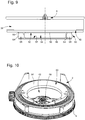
- a first electrically conductive contact area 50 for example in the form of a disk, is structured on the lower face of the second printed circuit sheet 42 and is in direct contact, for example with a negative terminal 52 of a power source. 54 such as a rechargeable battery or rechargeable battery ( figures 8 and 9 ).
- a second contact pad 56 for example of annular shape, is arranged concentrically around the first contact pad 50 and is intended to be connected to a positive terminal 58 of the electric power source 54.
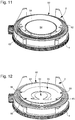
- the source electrical energy 54 is fixed under the second printed circuit sheet 42 by means of an electrically conductive fastening flange 60 and which is for example immobilized by means of fixing screws 62 ( figure 10 ).
- This fastening flange 60 is in contact with the second contact pad 56 via a rim 64 in an arc whose profile is identical to that of the second contact pad 56 and whose height is equal to the thickness of the source. electrical energy 54.
- the electrical connection between the electrical power source 54 and the second contact pad 56 is provided by a contact strip 66 which electrically connects the positive terminal 58 of the source of electricity with each other. electrical energy 54 and the mounting flange 60 ( Figures 11 and 12 ).
- This contact strip 66 is for example immobilized on the fixing flange 60 by means of fixing screws 68.
- the assembly formed by the dial 8, the first printed circuit sheet 16, the clockwork movement 36, the interlocking circle 38, the second printed circuit sheet 42 and the electrical energy source 54 are enclosed in the middle part 2 that is closed at the bottom by means of a bottom 70.
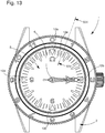
- an activation component of the at least one light source 28 is housed in the rotating bezel 4 ( figures 13 and 14 ).
- This activating component is typically a bipolar magnet 72 whose polarization direction 74 is oriented vertically.
- the presence of this bipolar magnet 72 is detected by a detection component such as a magnetic sensor 76 housed inside the box 1 of the wristwatch formed by the middle part 2 closed by the bottom 70.
- the magnetic sensor 76 is fixed on the connection tab 34. It is therefore understood that it is the position of the magnetic sensor 76 inside the box 1 of the wristwatch which determines the position of the rotating bezel 4 in which the presence of the bipolar magnet 72 is detected by the magnetic sensor 76.
- the magnetic sensor 76 When the presence of the bipolar magnet 72 is detected by the magnetic sensor 76, that is to say, in the case present, when the bipolar magnet 72 is above the magnetic sensor 76, the magnetic sensor 76 generates an electrical signal that will be sent to the microprocessor circuit 46. Upon receipt of this electrical signal, the microprocessor circuit Oesseur 46 emits an electrical signal which controls the lighting of the light source 28 for a predetermined period of time.
- An example of a magnetic sensor 76 well suited to the needs of the invention is provided by the very low power digital sensors marketed by the American company NVE Corporation in the ADL-Series range. These digital sensors are magneto-resistive type and are designed to operate at low voltage and with extremely low currents.
- These digital sensors function as magnetic “switches”, their output changing to “1” when a magnetic field is applied, and returning to "0" when the magnetic field is removed.
- These magnetic “switches” include a magneto-resistive magnetic field sensitive element and a CMOS signal processing device for converting the analog signal produced by the sensing element into a digital signal.
- the light sources 28 can be powered and controlled from outside the box 1 of the wristwatch according to the invention by means of a wire link 78 which passes through a hole 80 formed in the bottom of the case. watch case and which connects the light sources 28 to a power supply and control box 82 ( figure 15 ).
- connection tongues 340A, 340B and 340C may be provided around the periphery of the first printed circuit sheet 16, each of these connection tabs 340A-340C carrying a detection component 760A-760C which detects the presence of the activation component 72 in a corresponding determined position of the rotating bezel 4 (see Figures 16A and 16B ). More specifically, at figure 16A , the rotating bezel 4 is in a first position in which the presence of the activation component 72 is detected by a first detection component 760A and at the figure 16B the presence of the activation component 72 is detected by a second detection component 760B different from the first one.
- the electronic power supply and control assembly 32 comprises a generating component an alarm signal (sound or mechanical vibration) and equipped with an electromagnetic antenna for near-field communication.
- the generating component of the alarm signal can then be programmed for example with the help of a cell phone for the day and time of alarm.
Landscapes
- Physics & Mathematics (AREA)
- General Physics & Mathematics (AREA)
- Electric Clocks (AREA)
Claims (10)
- Armbanduhr, umfassend ein Uhrengehäuse (1), in dessen Innenraum ein Uhrwerk (36) eingebaut ist, eine an dem Uhrengehäuse (1) drehbar befestigte Lünette (4), und ein mit mindestens einem Leuchtzeichen (12a-12e) versehenes Zifferblatt (8), wobei dieses Leuchtzeichen (12a-12e) durch das Zifferblatt (8) hindurch durch mindestens eine Lichtquelle (28) beleuchtet wird, die unter dem Zifferblatt (8) angeordnet ist und durch eine Quelle (54) für elektrische Energie versorgt wird, wobei in der drehbaren Lünette (4) eine Komponente (72) zum Aktivieren der Lichtquelle (28) angeordnet ist, die mit einer in dem Uhrengehäuse (1) angeordneten Detektionskomponente (76) zusammenwirkt, wobei die Aktivierungskomponente (72) in einer Weise beschaffen ist, dass in einer bestimmten Position der drehbaren Lünette (4) ihr Vorhandensein durch die Detektionskomponente (76) detektiert wird, wobei die Detektionskomponente (76) dafür ausgelegt ist, daraufhin ein elektrisches Signal auszusenden, das an eine in dem Uhrengehäuse (1) angeordnete elektronische Versorgungs- und Steueranordnung (32) adressiert wird, wobei die elektronische Versorgungs- und Steueranordnung (32) dafür ausgelegt ist, in Reaktion auf den Empfang des von der Detektionskomponente (76) ausgesendeten elektrischen Signals ein elektrisches Signal auszusenden, das das Einschalten der Lichtquelle (28) während einer bestimmten Zeitspanne steuert, wobei die mindestens eine Lichtquelle (28) auf einer oberen Oberfläche (18) einer ersten gedruckten Leiterplatte (16) montiert ist, die unter einer unteren Oberfläche (20) des Zifferblatts (8) angeordnet ist, dadurch gekennzeichnet, dass die erste gedruckte Leiterplatte (16) über dem Uhrwerk (36) angeordnet ist und dass eine zweite gedruckte Leiterplatte (42), die die elektronische Versorgungs- und Steueranordnung (32) trägt, unter dem Uhrwerk (36) angeordnet ist, wobei die von der ersten gedruckten Leiterplatte (16) getragene Lichtquelle (28) mit der elektronischen Versorgungs- und Steueranordnung (32) über eine Verbindungslasche (34) elektrisch verbunden ist.
- Armbanduhr nach Anspruch 1, dadurch gekennzeichnet, dass die Aktivierungskomponente (72) ein bipolarer Magnet ist und dass die Detektionskomponente (74) ein magnetischer Sensor ist.
- Armbanduhr nach einem der Ansprüche 1 oder 2, dadurch gekennzeichnet, dass die untere Oberfläche (20) des Zifferblatts (8) an der Stelle, an der sich das mindestens eine Leuchtzeichen (12a-12e) befindet, das in dem Zifferblatt (8) angeordnet ist, mit einem Lichtleiter (22a-22d) versehen ist, in den das von der Lichtquelle (28) erzeugte Licht eingeleitet wird.
- Armbanduhr nach Anspruch 3, dadurch gekennzeichnet, dass der Lichtleiter (22a-22d) lichtstreuend ist.
- Armbanduhr nach Anspruch 3, dadurch gekennzeichnet, dass der Lichtleiter (22a-22d) lichtdurchlässig ist und dass Lichtauskoppler in dem Lichtleiter (22a-22d) ausgebildet sind, deren Funktion darin besteht, das Licht, das durch die Lichtquelle (28) eingeleitet wird, nach oben in Richtung zu dem Leuchtzeichen (12a-12e) auszukoppeln.
- Armbanduhr nach einem der Ansprüche 1 bis 5, dadurch gekennzeichnet, dass die erste gedruckte Leiterplatte (16) mit ihrer oberen Oberfläche (18) gegen die untere Oberfläche (20) des Zifferblatts (8) geklebt ist.
- Armbanduhr nach einem der Ansprüche 1 bis 6, dadurch gekennzeichnet, dass die Verbindungslasche (34) an einer Stelle des Umfangs der ersten gedruckten Leiterplatte (16) vorgesehen ist und in einen Verbinder (44) eingesetzt ist, der auf der zweiten gedruckten Leiterplatte (16) vorgesehen ist.
- Armbanduhr nach einem der Ansprüche 1 bis 7, dadurch gekennzeichnet, dass die Aktivierungskomponente (72) auf der Verbindungslasche (34) angeordnet ist.
- Armbanduhr nach einem der Ansprüche 1 bis 8, dadurch gekennzeichnet, dass ein erster elektrisch leitender Kontaktbereich (50) auf einer unteren Fläche der zweiten gedruckten Leiterplatte (42) ausgebildet ist und mit einem negativen Anschluss (52) einer Quelle (54) für elektrische Energie direkt in Kontakt steht und dass ein zweiter Kontaktbereich (56) mit einem positiven Anschluss (58) der Quelle (54) für elektrische Energie verbunden ist, wobei die Quelle (54) für elektrische Energie unter der zweiten gedruckten Leiterplatte (42) mittels eines elektrisch leitenden Befestigungsflansches (60) befestigt ist, der mit dem zweiten Kontaktbereich (56) in Kontakt steht und mit dem positiven Anschluss (58) der Quelle (54) für elektrische Energie über ein Kontaktplättchen (66) verbunden ist.
- Armbanduhr nach Anspruch 1, dadurch gekennzeichnet, dass die Lichtquelle (28) von außerhalb des Uhrengehäuses (1) versorgt und gesteuert wird mittels einer Drahtverbindung (78), die diese Lichtquelle (28) mit einem Versorgungs- und Steuergehäuse (80) verbindet.
Priority Applications (1)
| Application Number | Priority Date | Filing Date | Title |
|---|---|---|---|
| EP16705949.2A EP3087434B1 (de) | 2015-03-17 | 2016-02-23 | Armbanduhr, die ein zifferblatt mit leuchtindex umfasst |
Applications Claiming Priority (3)
| Application Number | Priority Date | Filing Date | Title |
|---|---|---|---|
| EP15159460.3A EP3070539A1 (de) | 2015-03-17 | 2015-03-17 | Armbanduhr, die ein zifferblatt mit leuchtindex umfasst |
| PCT/EP2016/053757 WO2016146350A1 (fr) | 2015-03-17 | 2016-02-23 | Montre-bracelet comprenant un cadran muni d'index lumineux |
| EP16705949.2A EP3087434B1 (de) | 2015-03-17 | 2016-02-23 | Armbanduhr, die ein zifferblatt mit leuchtindex umfasst |
Publications (2)
| Publication Number | Publication Date |
|---|---|
| EP3087434A1 EP3087434A1 (de) | 2016-11-02 |
| EP3087434B1 true EP3087434B1 (de) | 2018-01-31 |
Family
ID=52686203
Family Applications (2)
| Application Number | Title | Priority Date | Filing Date |
|---|---|---|---|
| EP15159460.3A Withdrawn EP3070539A1 (de) | 2015-03-17 | 2015-03-17 | Armbanduhr, die ein zifferblatt mit leuchtindex umfasst |
| EP16705949.2A Active EP3087434B1 (de) | 2015-03-17 | 2016-02-23 | Armbanduhr, die ein zifferblatt mit leuchtindex umfasst |
Family Applications Before (1)
| Application Number | Title | Priority Date | Filing Date |
|---|---|---|---|
| EP15159460.3A Withdrawn EP3070539A1 (de) | 2015-03-17 | 2015-03-17 | Armbanduhr, die ein zifferblatt mit leuchtindex umfasst |
Country Status (5)
| Country | Link |
|---|---|
| US (1) | US10338533B2 (de) |
| EP (2) | EP3070539A1 (de) |
| JP (1) | JP6242499B2 (de) |
| CN (1) | CN106662841B (de) |
| WO (1) | WO2016146350A1 (de) |
Families Citing this family (11)
| Publication number | Priority date | Publication date | Assignee | Title |
|---|---|---|---|---|
| JP2019029164A (ja) * | 2017-07-28 | 2019-02-21 | セイコーエプソン株式会社 | ウェアラブル機器 |
| CN109074030A (zh) * | 2017-10-26 | 2018-12-21 | 深圳市隐秀科技有限公司 | 一种交互式智能手表及其交互控制方法 |
| EP3572886B1 (de) * | 2018-05-23 | 2021-07-14 | The Swatch Group Research and Development Ltd | Armbanduhr, die ein element mit einem beleuchtbaren zeiger umfasst |
| CN109259391B (zh) * | 2018-11-21 | 2024-05-28 | 歌尔科技有限公司 | 一种腕戴设备 |
| EP3667436B1 (de) | 2018-12-14 | 2022-05-04 | The Swatch Group Research and Development Ltd | Uhr, die ein bewegliches element mit leuchtindex umfasst |
| EP3796103B1 (de) * | 2019-09-20 | 2025-06-18 | The Swatch Group Research and Development Ltd | Dekorartikel mit leuchteffekt |
| CN110716417B (zh) | 2019-09-23 | 2021-01-19 | 维沃移动通信有限公司 | 可穿戴设备及显示方法 |
| EP4102307A1 (de) | 2021-06-08 | 2022-12-14 | The Swatch Group Research and Development Ltd | Uhr mit lokalisierter beleuchtung |
| EP4109181A1 (de) * | 2021-06-21 | 2022-12-28 | ETA SA Manufacture Horlogère Suisse | Zifferblatt, armbanduhr mit einem solchen zifferblatt und verfahren zum einbau eines solchen zifferblatts in eine armbanduhr |
| CN115209594B (zh) * | 2022-09-09 | 2022-12-16 | 珠海市杰理科技股份有限公司 | 智能手表的控制方法、装置、智能手表、介质和程序产品 |
| EP4390560A1 (de) * | 2022-12-22 | 2024-06-26 | ETA SA Manufacture Horlogère Suisse | Uhrzifferblatt mit beleuchtungsvorrichtung |
Family Cites Families (19)
| Publication number | Priority date | Publication date | Assignee | Title |
|---|---|---|---|---|
| US687285A (en) * | 1901-08-13 | 1901-11-26 | Abraham Stein | Mustache-guard. |
| US2264554A (en) * | 1939-09-21 | 1941-12-02 | Roemmele Max Alexander | Device for dispensing substantially spherical articles |
| JPS51141666A (en) * | 1975-06-02 | 1976-12-06 | Seiko Epson Corp | Solar cell wrist watch |
| JPS55119984U (de) * | 1979-02-16 | 1980-08-25 | ||
| US4244044A (en) * | 1979-09-04 | 1981-01-06 | Olsson Mark S | Waterproof sport watch |
| CH687285B5 (fr) * | 1994-12-01 | 1997-05-15 | Manuf De Boites De Montres R V | Montre a lunette tournante et eclairage du cadran. |
| US6017127A (en) * | 1998-01-05 | 2000-01-25 | Timex Corporation | Illumination system for a dial of a timepiece |
| JP2000329875A (ja) * | 1999-05-17 | 2000-11-30 | Citizen Watch Co Ltd | デジタルウオッチの入力手段 |
| US20020101457A1 (en) * | 2001-01-31 | 2002-08-01 | Microsoft Corporation | Bezel interface for small computing devices |
| JP2003098272A (ja) * | 2001-07-17 | 2003-04-03 | Casio Comput Co Ltd | 電子機器および液晶表示装置 |
| JP2005016962A (ja) * | 2003-06-23 | 2005-01-20 | Seiko Epson Corp | 時計、時計の制御方法、制御プログラムおよび記録媒体 |
| EP1666992A1 (de) | 2004-12-02 | 2006-06-07 | Asulab S.A. | Uhr mit einer leuchtenden Dekoration |
| EP1918793A1 (de) * | 2006-11-03 | 2008-05-07 | ETA SA Manufacture Horlogère Suisse | Uhr, die mit einer Beleuchtungsvorrichtung ausgerüstet ist, welche eine Ultraviolett-Elektrolumineszenzdiode umfasst |
| CA2686642A1 (en) * | 2007-06-01 | 2008-12-04 | Merz Pharma Gmbh & Co. Kgaa | Process for providing a temperature - stable muscle relaxant on the basis of the neurotoxic component of botulinum toxin |
| US8045421B2 (en) * | 2008-01-17 | 2011-10-25 | Nike, Inc. | Watch with planar light diffusion channel |
| EP2392977B1 (de) * | 2009-06-18 | 2020-10-28 | ETA SA Manufacture Horlogère Suisse | Uhr mit speziellen ästhetischen effekten |
| CH701750A2 (fr) * | 2009-09-01 | 2011-03-15 | Eta Sa Mft Horlogere Suisse | Elément d'habillage pour une montre-bracelet. |
| US20110280110A1 (en) * | 2010-05-13 | 2011-11-17 | Ming-Hsien Chen | Indicator timepiece having light diffusing effect |
| CH707057A2 (fr) * | 2012-10-04 | 2014-04-15 | Swatch Group Res & Dev Ltd | Dispositif d'illumination d'un indicateur d'affichage d'un appareil horloger ou scientifique. |
-
2015
- 2015-03-17 EP EP15159460.3A patent/EP3070539A1/de not_active Withdrawn
-
2016
- 2016-02-23 WO PCT/EP2016/053757 patent/WO2016146350A1/fr not_active Ceased
- 2016-02-23 US US15/557,961 patent/US10338533B2/en active Active
- 2016-02-23 EP EP16705949.2A patent/EP3087434B1/de active Active
- 2016-02-23 JP JP2016552944A patent/JP6242499B2/ja active Active
- 2016-02-23 CN CN201680001186.XA patent/CN106662841B/zh active Active
Also Published As
| Publication number | Publication date |
|---|---|
| CN106662841A (zh) | 2017-05-10 |
| CN106662841B (zh) | 2019-02-22 |
| US10338533B2 (en) | 2019-07-02 |
| EP3070539A1 (de) | 2016-09-21 |
| US20180052426A1 (en) | 2018-02-22 |
| WO2016146350A1 (fr) | 2016-09-22 |
| EP3087434A1 (de) | 2016-11-02 |
| JP6242499B2 (ja) | 2017-12-06 |
| JP2017516067A (ja) | 2017-06-15 |
Similar Documents
| Publication | Publication Date | Title |
|---|---|---|
| EP3087434B1 (de) | Armbanduhr, die ein zifferblatt mit leuchtindex umfasst | |
| EP3579061B1 (de) | Schrein für eine elektromechanische uhr und baugruppe mit diesem | |
| EP2950168B1 (de) | Set aus Leuchtzeigern zum Anzeigen für tragbaren Gegenstand wie Armbanduhr oder Messinstrument | |
| EP1274150A1 (de) | Armbanduhr mit Antenne | |
| EP3156855B1 (de) | Mechanisches armbanduhr, die mit einer elektronischen funktion assoziert ist | |
| EP2874024A1 (de) | Perlmuttzifferblatt für versteckte Anzeigevorrichtung | |
| EP1540427B1 (de) | Uhr mit einem elektronischen modul zum informationspeichern, das im boden angeordnet ist | |
| EP2950167B1 (de) | Leuchtzeiger zum Anzeigen für tragbaren Gegenstand wie Armbanduhr oder Messinstrument | |
| EP1213629A1 (de) | Tragbare Vorrichtung, insbesondere Uhrwerk, mit einem in einem metallischen Gehäuse montierten wasserdichten Behälter | |
| EP3719586B1 (de) | Uhr mit besonderen ästhetischen effekten | |
| CH710879A2 (fr) | Montre-bracelet comprenant un cadran muni d'index lumineux. | |
| EP3637200B1 (de) | Leuchtanzeigevorrichtung | |
| EP1318437A1 (de) | Uhr mit Transponder, der wenigstens teilweise in einem Bedienungselement eingebaut ist | |
| CH717867B1 (fr) | Boite de montre. | |
| HK1237431B (zh) | 包括具有发光指示器的表盘的腕表 | |
| HK1237431A1 (en) | Wristwatch comprising a dial with luminous indices | |
| EP3667436B1 (de) | Uhr, die ein bewegliches element mit leuchtindex umfasst | |
| CH709720B1 (fr) | Jeu d'aiguilles d'affichage lumineuses pour objet portable tel qu'une montre ou un instrument de mesure. | |
| EP4390575A1 (de) | System zur einstellung einer beleuchtungsfunktion einer uhr | |
| CH698868B1 (fr) | Pièce d'horlogerie munie d'un dispositif d'éclairage comprenant une diode électroluminescente. | |
| CH701328A2 (fr) | Pièce d'horlogerie à effets esthétiques spéciaux. | |
| CH709719A2 (fr) | Aiguille d'affichage lumineuse pour objet portable tel qu'une montre ou un instrument de mesure. | |
| FR2638860A1 (fr) | Dispositif pour attirer l'attention d'usagers notamment pour la priere rituelle des musulmans | |
| CH701750A2 (fr) | Elément d'habillage pour une montre-bracelet. | |
| CH717017B1 (fr) | Indicateur mobile pour un dispositif d'affichage analogique comprenant une source stationnaire d'éclairage |
Legal Events
| Date | Code | Title | Description |
|---|---|---|---|
| PUAI | Public reference made under article 153(3) epc to a published international application that has entered the european phase |
Free format text: ORIGINAL CODE: 0009012 |
|
| 17P | Request for examination filed |
Effective date: 20160715 |
|
| AK | Designated contracting states |
Kind code of ref document: A1 Designated state(s): AL AT BE BG CH CY CZ DE DK EE ES FI FR GB GR HR HU IE IS IT LI LT LU LV MC MK MT NL NO PL PT RO RS SE SI SK SM TR |
|
| AX | Request for extension of the european patent |
Extension state: BA ME |
|
| GRAP | Despatch of communication of intention to grant a patent |
Free format text: ORIGINAL CODE: EPIDOSNIGR1 |
|
| DAV | Request for validation of the european patent (deleted) | ||
| DAX | Request for extension of the european patent (deleted) | ||
| INTG | Intention to grant announced |
Effective date: 20171024 |
|
| GRAS | Grant fee paid |
Free format text: ORIGINAL CODE: EPIDOSNIGR3 |
|
| GRAA | (expected) grant |
Free format text: ORIGINAL CODE: 0009210 |
|
| RIN1 | Information on inventor provided before grant (corrected) |
Inventor name: FERRI, YVAN Inventor name: TORTORA, PIERPASQUALE Inventor name: KISSLING, GREGORY Inventor name: CATANESE, ROCCO |
|
| AK | Designated contracting states |
Kind code of ref document: B1 Designated state(s): AL AT BE BG CH CY CZ DE DK EE ES FI FR GB GR HR HU IE IS IT LI LT LU LV MC MK MT NL NO PL PT RO RS SE SI SK SM TR |
|
| REG | Reference to a national code |
Ref country code: GB Ref legal event code: FG4D Free format text: NOT ENGLISH Ref country code: CH Ref legal event code: EP Ref country code: CH Ref legal event code: NV Representative=s name: ICB INGENIEURS CONSEILS EN BREVETS SA, CH |
|
| REG | Reference to a national code |
Ref country code: AT Ref legal event code: REF Ref document number: 967922 Country of ref document: AT Kind code of ref document: T Effective date: 20180215 |
|
| REG | Reference to a national code |
Ref country code: FR Ref legal event code: PLFP Year of fee payment: 3 |
|
| REG | Reference to a national code |
Ref country code: IE Ref legal event code: FG4D Free format text: LANGUAGE OF EP DOCUMENT: FRENCH |
|
| REG | Reference to a national code |
Ref country code: DE Ref legal event code: R096 Ref document number: 602016001562 Country of ref document: DE |
|
| REG | Reference to a national code |
Ref country code: NL Ref legal event code: MP Effective date: 20180131 |
|
| REG | Reference to a national code |
Ref country code: LT Ref legal event code: MG4D |
|
| REG | Reference to a national code |
Ref country code: AT Ref legal event code: MK05 Ref document number: 967922 Country of ref document: AT Kind code of ref document: T Effective date: 20180131 |
|
| PG25 | Lapsed in a contracting state [announced via postgrant information from national office to epo] |
Ref country code: NL Free format text: LAPSE BECAUSE OF FAILURE TO SUBMIT A TRANSLATION OF THE DESCRIPTION OR TO PAY THE FEE WITHIN THE PRESCRIBED TIME-LIMIT Effective date: 20180131 Ref country code: NO Free format text: LAPSE BECAUSE OF FAILURE TO SUBMIT A TRANSLATION OF THE DESCRIPTION OR TO PAY THE FEE WITHIN THE PRESCRIBED TIME-LIMIT Effective date: 20180430 Ref country code: LT Free format text: LAPSE BECAUSE OF FAILURE TO SUBMIT A TRANSLATION OF THE DESCRIPTION OR TO PAY THE FEE WITHIN THE PRESCRIBED TIME-LIMIT Effective date: 20180131 Ref country code: ES Free format text: LAPSE BECAUSE OF FAILURE TO SUBMIT A TRANSLATION OF THE DESCRIPTION OR TO PAY THE FEE WITHIN THE PRESCRIBED TIME-LIMIT Effective date: 20180131 Ref country code: HR Free format text: LAPSE BECAUSE OF FAILURE TO SUBMIT A TRANSLATION OF THE DESCRIPTION OR TO PAY THE FEE WITHIN THE PRESCRIBED TIME-LIMIT Effective date: 20180131 Ref country code: FI Free format text: LAPSE BECAUSE OF FAILURE TO SUBMIT A TRANSLATION OF THE DESCRIPTION OR TO PAY THE FEE WITHIN THE PRESCRIBED TIME-LIMIT Effective date: 20180131 |
|
| PG25 | Lapsed in a contracting state [announced via postgrant information from national office to epo] |
Ref country code: IS Free format text: LAPSE BECAUSE OF FAILURE TO SUBMIT A TRANSLATION OF THE DESCRIPTION OR TO PAY THE FEE WITHIN THE PRESCRIBED TIME-LIMIT Effective date: 20180531 Ref country code: BG Free format text: LAPSE BECAUSE OF FAILURE TO SUBMIT A TRANSLATION OF THE DESCRIPTION OR TO PAY THE FEE WITHIN THE PRESCRIBED TIME-LIMIT Effective date: 20180430 Ref country code: PL Free format text: LAPSE BECAUSE OF FAILURE TO SUBMIT A TRANSLATION OF THE DESCRIPTION OR TO PAY THE FEE WITHIN THE PRESCRIBED TIME-LIMIT Effective date: 20180131 Ref country code: GR Free format text: LAPSE BECAUSE OF FAILURE TO SUBMIT A TRANSLATION OF THE DESCRIPTION OR TO PAY THE FEE WITHIN THE PRESCRIBED TIME-LIMIT Effective date: 20180501 Ref country code: SE Free format text: LAPSE BECAUSE OF FAILURE TO SUBMIT A TRANSLATION OF THE DESCRIPTION OR TO PAY THE FEE WITHIN THE PRESCRIBED TIME-LIMIT Effective date: 20180131 Ref country code: LV Free format text: LAPSE BECAUSE OF FAILURE TO SUBMIT A TRANSLATION OF THE DESCRIPTION OR TO PAY THE FEE WITHIN THE PRESCRIBED TIME-LIMIT Effective date: 20180131 Ref country code: AT Free format text: LAPSE BECAUSE OF FAILURE TO SUBMIT A TRANSLATION OF THE DESCRIPTION OR TO PAY THE FEE WITHIN THE PRESCRIBED TIME-LIMIT Effective date: 20180131 Ref country code: RS Free format text: LAPSE BECAUSE OF FAILURE TO SUBMIT A TRANSLATION OF THE DESCRIPTION OR TO PAY THE FEE WITHIN THE PRESCRIBED TIME-LIMIT Effective date: 20180131 |
|
| PG25 | Lapsed in a contracting state [announced via postgrant information from national office to epo] |
Ref country code: MT Free format text: LAPSE BECAUSE OF FAILURE TO SUBMIT A TRANSLATION OF THE DESCRIPTION OR TO PAY THE FEE WITHIN THE PRESCRIBED TIME-LIMIT Effective date: 20180131 |
|
| PG25 | Lapsed in a contracting state [announced via postgrant information from national office to epo] |
Ref country code: RO Free format text: LAPSE BECAUSE OF FAILURE TO SUBMIT A TRANSLATION OF THE DESCRIPTION OR TO PAY THE FEE WITHIN THE PRESCRIBED TIME-LIMIT Effective date: 20180131 Ref country code: IT Free format text: LAPSE BECAUSE OF FAILURE TO SUBMIT A TRANSLATION OF THE DESCRIPTION OR TO PAY THE FEE WITHIN THE PRESCRIBED TIME-LIMIT Effective date: 20180131 Ref country code: EE Free format text: LAPSE BECAUSE OF FAILURE TO SUBMIT A TRANSLATION OF THE DESCRIPTION OR TO PAY THE FEE WITHIN THE PRESCRIBED TIME-LIMIT Effective date: 20180131 Ref country code: AL Free format text: LAPSE BECAUSE OF FAILURE TO SUBMIT A TRANSLATION OF THE DESCRIPTION OR TO PAY THE FEE WITHIN THE PRESCRIBED TIME-LIMIT Effective date: 20180131 |
|
| REG | Reference to a national code |
Ref country code: DE Ref legal event code: R097 Ref document number: 602016001562 Country of ref document: DE |
|
| REG | Reference to a national code |
Ref country code: IE Ref legal event code: MM4A |
|
| REG | Reference to a national code |
Ref country code: BE Ref legal event code: MM Effective date: 20180228 |
|
| PG25 | Lapsed in a contracting state [announced via postgrant information from national office to epo] |
Ref country code: CZ Free format text: LAPSE BECAUSE OF FAILURE TO SUBMIT A TRANSLATION OF THE DESCRIPTION OR TO PAY THE FEE WITHIN THE PRESCRIBED TIME-LIMIT Effective date: 20180131 Ref country code: DK Free format text: LAPSE BECAUSE OF FAILURE TO SUBMIT A TRANSLATION OF THE DESCRIPTION OR TO PAY THE FEE WITHIN THE PRESCRIBED TIME-LIMIT Effective date: 20180131 Ref country code: SM Free format text: LAPSE BECAUSE OF FAILURE TO SUBMIT A TRANSLATION OF THE DESCRIPTION OR TO PAY THE FEE WITHIN THE PRESCRIBED TIME-LIMIT Effective date: 20180131 Ref country code: SK Free format text: LAPSE BECAUSE OF FAILURE TO SUBMIT A TRANSLATION OF THE DESCRIPTION OR TO PAY THE FEE WITHIN THE PRESCRIBED TIME-LIMIT Effective date: 20180131 Ref country code: LU Free format text: LAPSE BECAUSE OF NON-PAYMENT OF DUE FEES Effective date: 20180223 Ref country code: MC Free format text: LAPSE BECAUSE OF FAILURE TO SUBMIT A TRANSLATION OF THE DESCRIPTION OR TO PAY THE FEE WITHIN THE PRESCRIBED TIME-LIMIT Effective date: 20180131 |
|
| PLBE | No opposition filed within time limit |
Free format text: ORIGINAL CODE: 0009261 |
|
| STAA | Information on the status of an ep patent application or granted ep patent |
Free format text: STATUS: NO OPPOSITION FILED WITHIN TIME LIMIT |
|
| 26N | No opposition filed |
Effective date: 20181102 |
|
| PG25 | Lapsed in a contracting state [announced via postgrant information from national office to epo] |
Ref country code: IE Free format text: LAPSE BECAUSE OF NON-PAYMENT OF DUE FEES Effective date: 20180223 |
|
| PG25 | Lapsed in a contracting state [announced via postgrant information from national office to epo] |
Ref country code: BE Free format text: LAPSE BECAUSE OF NON-PAYMENT OF DUE FEES Effective date: 20180228 Ref country code: SI Free format text: LAPSE BECAUSE OF FAILURE TO SUBMIT A TRANSLATION OF THE DESCRIPTION OR TO PAY THE FEE WITHIN THE PRESCRIBED TIME-LIMIT Effective date: 20180131 |
|
| PG25 | Lapsed in a contracting state [announced via postgrant information from national office to epo] |
Ref country code: TR Free format text: LAPSE BECAUSE OF FAILURE TO SUBMIT A TRANSLATION OF THE DESCRIPTION OR TO PAY THE FEE WITHIN THE PRESCRIBED TIME-LIMIT Effective date: 20180131 |
|
| PG25 | Lapsed in a contracting state [announced via postgrant information from national office to epo] |
Ref country code: PT Free format text: LAPSE BECAUSE OF FAILURE TO SUBMIT A TRANSLATION OF THE DESCRIPTION OR TO PAY THE FEE WITHIN THE PRESCRIBED TIME-LIMIT Effective date: 20180131 |
|
| PG25 | Lapsed in a contracting state [announced via postgrant information from national office to epo] |
Ref country code: HU Free format text: LAPSE BECAUSE OF FAILURE TO SUBMIT A TRANSLATION OF THE DESCRIPTION OR TO PAY THE FEE WITHIN THE PRESCRIBED TIME-LIMIT; INVALID AB INITIO Effective date: 20160223 Ref country code: CY Free format text: LAPSE BECAUSE OF FAILURE TO SUBMIT A TRANSLATION OF THE DESCRIPTION OR TO PAY THE FEE WITHIN THE PRESCRIBED TIME-LIMIT Effective date: 20180131 Ref country code: MK Free format text: LAPSE BECAUSE OF NON-PAYMENT OF DUE FEES Effective date: 20180131 |
|
| P01 | Opt-out of the competence of the unified patent court (upc) registered |
Effective date: 20230701 |
|
| PGFP | Annual fee paid to national office [announced via postgrant information from national office to epo] |
Ref country code: CH Payment date: 20250301 Year of fee payment: 10 |
|
| REG | Reference to a national code |
Ref country code: CH Ref legal event code: U11 Free format text: ST27 STATUS EVENT CODE: U-0-0-U10-U11 (AS PROVIDED BY THE NATIONAL OFFICE) Effective date: 20260301 |
|
| PGFP | Annual fee paid to national office [announced via postgrant information from national office to epo] |
Ref country code: GB Payment date: 20260122 Year of fee payment: 11 |
|
| PGFP | Annual fee paid to national office [announced via postgrant information from national office to epo] |
Ref country code: DE Payment date: 20260121 Year of fee payment: 11 |
|
| PGFP | Annual fee paid to national office [announced via postgrant information from national office to epo] |
Ref country code: FR Payment date: 20260121 Year of fee payment: 11 |