EP3087905A1 - Abbildungsvorrichtung eines elektronischen endoskops und elektronisches endoskop - Google Patents
Abbildungsvorrichtung eines elektronischen endoskops und elektronisches endoskop Download PDFInfo
- Publication number
- EP3087905A1 EP3087905A1 EP16175542.6A EP16175542A EP3087905A1 EP 3087905 A1 EP3087905 A1 EP 3087905A1 EP 16175542 A EP16175542 A EP 16175542A EP 3087905 A1 EP3087905 A1 EP 3087905A1
- Authority
- EP
- European Patent Office
- Prior art keywords
- circuit board
- electronic endoscope
- cover glass
- solid
- imaging device
- Prior art date
- Legal status (The legal status is an assumption and is not a legal conclusion. Google has not performed a legal analysis and makes no representation as to the accuracy of the status listed.)
- Withdrawn
Links
Images


Classifications
-
- A—HUMAN NECESSITIES
- A61—MEDICAL OR VETERINARY SCIENCE; HYGIENE
- A61B—DIAGNOSIS; SURGERY; IDENTIFICATION
- A61B1/00—Instruments for performing medical examinations of the interior of cavities or tubes of the body by visual or photographical inspection, e.g. endoscopes; Illuminating arrangements therefor
- A61B1/04—Instruments for performing medical examinations of the interior of cavities or tubes of the body by visual or photographical inspection, e.g. endoscopes; Illuminating arrangements therefor combined with photographic or television appliances
- A61B1/05—Instruments for performing medical examinations of the interior of cavities or tubes of the body by visual or photographical inspection, e.g. endoscopes; Illuminating arrangements therefor combined with photographic or television appliances characterised by the image sensor, e.g. camera, being in the distal end portion
-
- A—HUMAN NECESSITIES
- A61—MEDICAL OR VETERINARY SCIENCE; HYGIENE
- A61B—DIAGNOSIS; SURGERY; IDENTIFICATION
- A61B1/00—Instruments for performing medical examinations of the interior of cavities or tubes of the body by visual or photographical inspection, e.g. endoscopes; Illuminating arrangements therefor
- A61B1/04—Instruments for performing medical examinations of the interior of cavities or tubes of the body by visual or photographical inspection, e.g. endoscopes; Illuminating arrangements therefor combined with photographic or television appliances
- A61B1/042—Instruments for performing medical examinations of the interior of cavities or tubes of the body by visual or photographical inspection, e.g. endoscopes; Illuminating arrangements therefor combined with photographic or television appliances characterised by a proximal camera, e.g. a CCD camera
-
- A—HUMAN NECESSITIES
- A61—MEDICAL OR VETERINARY SCIENCE; HYGIENE
- A61B—DIAGNOSIS; SURGERY; IDENTIFICATION
- A61B1/00—Instruments for performing medical examinations of the interior of cavities or tubes of the body by visual or photographical inspection, e.g. endoscopes; Illuminating arrangements therefor
- A61B1/04—Instruments for performing medical examinations of the interior of cavities or tubes of the body by visual or photographical inspection, e.g. endoscopes; Illuminating arrangements therefor combined with photographic or television appliances
- A61B1/05—Instruments for performing medical examinations of the interior of cavities or tubes of the body by visual or photographical inspection, e.g. endoscopes; Illuminating arrangements therefor combined with photographic or television appliances characterised by the image sensor, e.g. camera, being in the distal end portion
- A61B1/051—Details of CCD assembly
-
- A—HUMAN NECESSITIES
- A61—MEDICAL OR VETERINARY SCIENCE; HYGIENE
- A61B—DIAGNOSIS; SURGERY; IDENTIFICATION
- A61B1/00—Instruments for performing medical examinations of the interior of cavities or tubes of the body by visual or photographical inspection, e.g. endoscopes; Illuminating arrangements therefor
- A61B1/12—Instruments for performing medical examinations of the interior of cavities or tubes of the body by visual or photographical inspection, e.g. endoscopes; Illuminating arrangements therefor with cooling or rinsing arrangements
- A61B1/128—Instruments for performing medical examinations of the interior of cavities or tubes of the body by visual or photographical inspection, e.g. endoscopes; Illuminating arrangements therefor with cooling or rinsing arrangements provided with means for regulating temperature
Definitions
- the present invention relates to an imaging apparatus of an electronic endoscope for taking an image inside of the coelom, and an electronic endoscope including the imaging apparatus.
- a medical diagnosis utilizing an electronic endoscope has been actively carried out in a medical field.
- a front end of an inserting portion of an electronic endoscope inserted into a coelom includes an imaging apparatus having a solid-state imaging device such as CCD and the like.
- An image inside of the coelom can be observed with a monitor by subjecting an imaging signal output from CCD to various signal processings by a processor apparatus.
- the imaging apparatus includes the CCD mentioned above and an object optical system for taking in image light of an observed portion inside of the coelom, the image light being incident from an observation window provided at the front end of the inserting portion.
- a cover glass is arranged above an imaging surface (light receiving surface) of CCD to be spaced apart from each other therebetween by a gap (air gap).
- the front end of the inserting portion of the electronic endoscope inserted into the coelom is brought into a temperature to a degree the same as that of the physical temperature (about 37°C).
- a temperature inside of the inserting portion becomes higher than the physical temperature to be occasionally equal to or higher than 40°C by heat of driving an electronic part of CCD or the like.
- an inner surface of the cover glass is proximate to an imaging surface of CCD, and therefore, a temperature thereof is liable to be high, on the other hand, there is a case in which an outer surface of the cover glass is rapidly cooled by injecting cleaning water or the like, and therefore, dew condensation is produced at an inner surface of the cover glass by moisture included in the air gap.
- JP-A-2003-284686 discloses an imaging apparatus of an electronic endoscope, in which a heat generating member such as a peripheral circuit of a solid-state imaging device is disposed at a vicinity of a cover glass to warm up an outer surface of the cover glass.
- JP-A-2003-284686 describes a first embodiment using only the peripheral circuit as a heat generating member, in addition, a second embodiment using a board extended substantially in a channel-like shape to surround the cover glass in three directions, and a third embodiment providing a heater in place of the peripheral circuit.
- the peripheral circuit is mounted to the board.
- the board generally includes a material whose major component is alumina from reason of being inexpensive, easy to fabricate or the like.
- a heat conductivity of the board including the material whose major component is alumina is high, and therefore, heat of the peripheral circuit is escaped to a side of an operating portion on the hand side of the electronic endoscope by way of a wiring connected to the peripheral circuit. Therefore, even when a surface of the cover glass is intended to warm up by heat of the peripheral circuit, heat is not transferred efficiently to the surface of the cover glass. Therefore, according to the invention described in JP-A-2003-284686 , it is necessary to use the extended board having a special shape or provide the heater, and hence fabrication cost and part cost are increased.
- An object of an illustrative, non-limiting embodiment of the invention is to provide an imaging apparatus of an electronic endoscope and an electronic endoscope, which are capable of efficiently and firmly preventing dew condensation of a cover glass attached to a solid-state imaging device by an inexpensive constitution.
- an imaging apparatus of an electronic endoscope including: a solid-state imaging device that receives image light of an observed portion inside of a coelom to output an imaging signal of the image light; a cover glass disposed above an light receiving surface (imaging surface) of the solid-state imaging device so that the cover glass and the solid-state imaging device are separated with a space; and a first circuit board disposed at a vicinity of an upper surface of the cover glass and including a peripheral circuit of the solid-state imaging device, the first circuit board having a thermal conductivity lower than that of a circuit board whose major component is alumina, the imaging apparatus being included in a front end of an electronic endoscope.
- the thermal conductivity of the first circuit board may be at least equal to or lower than 1/5 of the thermal conductivity of the circuit board whose major component is alumina.
- the first circuit board may include a material whose major component is a mixture material of alumina and glass baked at a low temperature (preferably less than 1,000 °C, more preferably about 900 °C).
- the alumina may be mixed in an amount of 40 to 60%
- the glass may be mixed in an amount of 40 to 60% (incidentally, the total amount of the alumina and the glass does not exceed 100%).
- the imaging apparatus may include a second circuit board disposed at a lower surface or a side surface of the solid-state imaging device and including a peripheral circuit of the solid-state imaging device, in which a thermal conductivity of the second circuit board is higher than that of the circuit board whose major component is alumina.
- the thermal conductivity of the second circuit board may be at least 5 times as much as that of the circuit board whose major component is alumina.
- the second circuit board may include a material whose major component is aluminum nitride baked at a high temperature (preferably more than 1,000 °C, more preferably about 1,500 °C).
- an electronic endoscope including the imaging apparatus.
- the cover glass is warmed up by the board having the thermal conductivity lower than the thermal conductivity of the circuit board whose major component is alumina, and therefore, dew condensation of the cover glass attached to the solid-state imaging device can efficiently and firmly be prevented by an inexpensive constitution.
- an electronic endoscope system 2 includes an electronic endoscope 10, a processor apparatus 11, and a light source apparatus (not illustrated) or the like.
- the electronic endoscope 10 includes an inserting portion 12 inserted into a coelom, an operating portion 13 continuously provided to a base end portion of the inserting portion 12, and a cord 14 connected to the processor apparatus 11 and the light source apparatus.
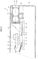
- a front end portion 12a continuously provided to a front end of the inserting portion 12 includes an imaging apparatus 15 (refer to Fig.2 ) for taking an image inside of the coelom. Further, a rear side of the front end portion 12a is provided with a bend portion 16 connected with a plurality of bend nodes. The bend portion 16 is operated to bend in an up and down direction and in a left and right direction by pushing and pulling a wire inserted into the inserting portion 12 by operating an angle knob 13a provided at the operating portion 13. Thereby, the front end portion 12a is directed in a desired direction inside of the coelom.
- the operating portion 13 is provided with a forceps port 17 into which a treatment piece is inserted.
- the forceps port 17 is connected to a forceps channel 18 arranged inside of the inserting portion 12 as shown by a dotted line.
- the processor apparatus 11 is provided with circuits (mentioned later) for subjecting an imaging signal acquired by the imaging apparatus 15 to various processings.
- the light source apparatus is mounted with a light source or the like for supplying illuminating light to the electronic endoscope 10 by way of the cord 14. An image inside of the coelom taken by imaging apparatus 15 is displayed on a monitor 19 connected to the processor apparatus 11.
- the front end portion 12a is provided with an observation window 20.
- a lens barrel 22 for holding an object optical system (lens group) 21 for taking in image light of the observed portion inside of the coelom.
- the lens barrel 22 is attached such that an optical axis 21a of the object optical system 21 becomes in parallel with a center axis 12b of the inserting portion 12.
- the front end portion 12a is provided with an illumination window for illuminating illumination light from the light source apparatus at the observed portion inside of the coelom, a forceps outlet continuously provided to the forceps port 17 by way of the forceps channel 18, a nozzle for injecting cleaning water or air for removing stain of the observation window 20 by operating an air blowing/water delivering button 13b (refer to Fig. 1 ) and the like.
- a rear end of the lens barrel 22 is connected with a prism 24 for guiding image light of the observed portion by way of the object optical system 21 to an imaging surface (light receiving surface) 23a of CCD 23.
- a prism 24 for guiding image light of the observed portion by way of the object optical system 21 to an imaging surface (light receiving surface) 23a of CCD 23.
- an incident surface thereof is connected to the object optical system 21, and an emitting surface thereof is connected to cover glass 26 mentioned later, respectively.
- the optical axis 21a of the object optical system 21 and the imaging surface 23a are arranged to be parallel.
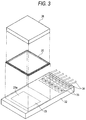
- CCD 23 includes, for example, an interline type CCD, and a bare chip provided with the imaging surface 23a on a surface of the bare chip is used. Also as shown in Fig.3 , the cover glass 26 in a shape of a rectangular plate is attached onto the imaging surface 23a by way of a spacer 25 in a shape of a quadrangular frame. CCD 23, the spacer 25, and the cover glass 26 are integrated by being adhered to each other by an adhering agent.
- a vicinity of an upper surface of the cover glass 26 is arranged with a first circuit board 28 mounted with a peripheral circuit 27.
- the peripheral circuit 27 is connected with a cable 30 by way of a terminal 29.
- the peripheral circuit 27 includes, for example, a circuit lowering an output impedance so as not to bring about signal attenuation or unnecessary reflection and achieving impedance matching.
- the peripheral circuit 27 is sealed by a sealing agent 31 of one-component curable epoxy resin or the like. The sealing agent 31 is brought into contact with a rear end of the cover glass 26, thereby, the first circuit board 28 is held at an illustrated position.
- the first circuit board 28 having a thermal conductivity lower than a thermal conductivity of a circuit board whose major component is alumina (alumina 90% or more, thermal conductivity 10 to 30W/mK, for example, alumina 96%, thermal conductivity 14 to 18W/mK).
- the first circuit board 28 is provided with a thermal conductivity equal to or smaller than at least 1/5 of the thermal conductivity of the circuit board whose major component is alumina, or 1/5 through 1/4 or less as a preferable range.
- an alumina glass board (thermal conductivity 2 to 3W/mK) mixed with alumina in an amount of 40 to 60%, and glass in an amount of 40 to 60% (incidentally, the total amount of the alumina and the glass does not exceed 100%) and formed by being baked at a high temperature.
- amounts of the alumina and the glass although it may be preferred that the amount of the alumina is 50% and the amount of the glass, a similar effect can be achieved even when other component in an amount of several percents is mixed thereto.
- a lower surface of CCD 23 is provided with a second circuit board 32.
- the second circuit board 32 holds CCD 23 to cover a lower surface and a side surface of CCD 23.
- the second circuit board 32 is mounted with, for example, a circuit of transmitting a drive signal (not illustrated) for driving CCD 23 or the like as a peripheral circuit.
- a rear end portion of the second circuit board 32 extended to a rear end of the inserting portion 12 is provided with a plurality of input/output terminals 33.
- the input/output terminals 33 are soldered with signal lines 34 for intermediating in exchanging various signals with the processor apparatus 11 by way of the cord 14.
- CCD 23 is connected with an amplifier (hereinafter, abbreviated as AMP) 40 and a CCD driver 41 provided to the processor apparatus 11.
- AMP 40 amplifies the imaging signal output from CCD 23 by a gain to output to a correlation double sampling programmable gain amplifier (hereinafter, abbreviated as CDS/PGA) 42.
- CDS/PGA correlation double sampling programmable gain amplifier
- CDS/PGA 42 outputs the imaging signal outputted from AMP 40 as image data of R, G, B accurately in correspondence with stored electric charge amounts of respective cells of CCD 23 and amplifies the image data to output to an A/D converter (hereinafter, abbreviated as A/D) 43.
- A/D 43 converts analog image data outputted from CDS/PGA 42 into digital image data.
- An image processing section 44 subjects image data digitized by A/D 43 to various image processings to output the image inside of the coelom to the monitor 19.
- the CCD driver 41 is connected with a timing generator (hereinafter, abbreviated as TG) 46 controlled by CPU 45.
- TG timing generator
- the CCD driver 41 controls a shutter speed of an electronic shutter of CCD 23 by a timing signal (clock pulse) inputted from TG 46.
- the light source apparatus When the inside of the coelom is observed by the electronic endoscope system 2 constituted as described above, the light source apparatus is made ON, the inserting portion 12 is inserted into the coelom, and the image inside of the coelom by CCD 23 is observed by the monitor 19 while illuminating the inside of the coelom.
- the CCD driver 41 and the like are started and the image light of the observed portion is taken by CCD 23.
- the image light of the observed portion taken in from the object optical system 21 or the like is focused onto the imaging surface 23a by way of the prism 24, thereby, the imaging signal is output from CCD 23.
- the imaging signal outputted from CCD 23 is amplified by AMP 40, subjected to correlation double sampling and amplification by CDS/PGA 42, and converted into the digital image data by A/D 43.
- the image data digitized by A/D 43 is subjected to various image processings by the image processing section 44, thereafter, displayed on the monitor 19 as the image.
- the peripheral circuit 27 When CCD 23 is driven, the peripheral circuit 27 generates heat, and the first circuit board 28 mounted with the peripheral circuit 27 is heated.
- the thermal conductivity of the first circuit board 28 is lower than that of the circuit board whose major component is alumina, and therefore, in comparison with the case of using the circuit board whose major component is alumina, heat from the peripheral circuit 27 is more stored. That is, the heat of the peripheral circuit 27 is difficult to be transferred to the cable 30 and the heat is difficult to escape to the side of the operating portion 13.
- the first circuit board 28 is arranged at the vicinity of the upper surface of the cover glass 26, and therefore, the heat of the first circuit board 28 reaches to warm up an outer face of the cover glass 26 (a face on a side of being connected with the prism 24).
- the outer surface of the cover glass is cooled when the power source of the electronic endoscope 10 is made ON, or when cleaning water or air is injected to the observation window 20, an inner surface of the cover glass (a surface on a side of CCD23) is heated by heat of driving CCD 23 and the second circuit board 32. Therefore, a temperature difference is produced between the outer surface and the inner surface of the cover glass 26 and dew condensation is brought about at the inner face of the cover glass 26.
- the outer surface of the cover glass 26 is warmed up by the heat of the first circuit board 28 having the thermal conductivity lower than that of the circuit board whose major component is alumina, and therefore, the outer surface and the inner surface of the cover glass 26 is brought into a thermally balanced state to prevent dew condensation.
- the thermal conductivity of the first circuit board 28 arranged at the vicinity of the upper surface of the cover glass 26 is made to be lower than that of the circuit board whose major component is alumina, and therefore, dew condensation of the cover glass 26 can firmly be prevented without providing a board having a special shape or a heater.
- the second circuit board 32 having the thermal conductivity higher than that of the circuit constitution whose major component is alumina. Specifically, there is used the second circuit board 32 having the thermal conductivity at least 5 times as much as that of the circuit board whose major component is alumina or more, or 5 times through 10 times or more of the thermal conductivity of the circuit board whose major component is alumina as a preferable range.
- an aluminum nitride board thermal conductivity 80 through 150W/mK formed by baking a material whose major component is aluminum nitride at a high temperature.
- the spacer 25 is used such that CCD 23 and the cover glass 26 are spaced apart from each other by the gap therebetween, in place of the spacer 25, a transparent adhering agent may be used, or the cover glass 26 may be formed with a leg.
- circuits of AMP 40, the CCD driver 41 and the like are mounted to a side of the processor apparatus 11, the circuits may be provided on a side of the electronic endoscope 10.
- the invention is applicable also to an electronic endoscope of a side viewing type in which the center axis 12b and the optical axis 21 a are orthogonal to each other.
Landscapes
- Health & Medical Sciences (AREA)
- Life Sciences & Earth Sciences (AREA)
- Surgery (AREA)
- Biomedical Technology (AREA)
- Medical Informatics (AREA)
- Optics & Photonics (AREA)
- Pathology (AREA)
- Radiology & Medical Imaging (AREA)
- Biophysics (AREA)
- Engineering & Computer Science (AREA)
- Physics & Mathematics (AREA)
- Heart & Thoracic Surgery (AREA)
- Nuclear Medicine, Radiotherapy & Molecular Imaging (AREA)
- Molecular Biology (AREA)
- Animal Behavior & Ethology (AREA)
- General Health & Medical Sciences (AREA)
- Public Health (AREA)
- Veterinary Medicine (AREA)
- Endoscopes (AREA)
- Instruments For Viewing The Inside Of Hollow Bodies (AREA)
- Studio Devices (AREA)
Applications Claiming Priority (2)
| Application Number | Priority Date | Filing Date | Title |
|---|---|---|---|
| JP2007087026A JP2008245668A (ja) | 2007-03-29 | 2007-03-29 | 電子内視鏡の撮像装置、および電子内視鏡 |
| EP08004109.8A EP1974654B1 (de) | 2007-03-29 | 2008-03-05 | Abbildungsvorrichtung eines elektronischen Endoskops und elektronisches Endoskop |
Related Parent Applications (2)
| Application Number | Title | Priority Date | Filing Date |
|---|---|---|---|
| EP08004109.8A Division EP1974654B1 (de) | 2007-03-29 | 2008-03-05 | Abbildungsvorrichtung eines elektronischen Endoskops und elektronisches Endoskop |
| EP08004109.8A Division-Into EP1974654B1 (de) | 2007-03-29 | 2008-03-05 | Abbildungsvorrichtung eines elektronischen Endoskops und elektronisches Endoskop |
Publications (1)
| Publication Number | Publication Date |
|---|---|
| EP3087905A1 true EP3087905A1 (de) | 2016-11-02 |
Family
ID=39492112
Family Applications (2)
| Application Number | Title | Priority Date | Filing Date |
|---|---|---|---|
| EP16175542.6A Withdrawn EP3087905A1 (de) | 2007-03-29 | 2008-03-05 | Abbildungsvorrichtung eines elektronischen endoskops und elektronisches endoskop |
| EP08004109.8A Not-in-force EP1974654B1 (de) | 2007-03-29 | 2008-03-05 | Abbildungsvorrichtung eines elektronischen Endoskops und elektronisches Endoskop |
Family Applications After (1)
| Application Number | Title | Priority Date | Filing Date |
|---|---|---|---|
| EP08004109.8A Not-in-force EP1974654B1 (de) | 2007-03-29 | 2008-03-05 | Abbildungsvorrichtung eines elektronischen Endoskops und elektronisches Endoskop |
Country Status (3)
| Country | Link |
|---|---|
| US (1) | US8462202B2 (de) |
| EP (2) | EP3087905A1 (de) |
| JP (1) | JP2008245668A (de) |
Families Citing this family (9)
| Publication number | Priority date | Publication date | Assignee | Title |
|---|---|---|---|---|
| DE102009011479A1 (de) | 2009-03-06 | 2010-09-09 | Olympus Winter & Ibe Gmbh | Chirurgisches Instrument |
| DE102009013615A1 (de) * | 2009-03-17 | 2010-09-23 | Kaltenbach & Voigt Gmbh | Medizinisches, insbesondere zahnmedizinisches Diagnosegerät mit Bilderfassungsmitteln |
| JP5303414B2 (ja) * | 2009-09-25 | 2013-10-02 | 富士フイルム株式会社 | 撮像装置及び内視鏡 |
| JP2011206077A (ja) * | 2010-03-26 | 2011-10-20 | Fujifilm Corp | 撮像装置及び内視鏡 |
| JP2011206079A (ja) * | 2010-03-26 | 2011-10-20 | Fujifilm Corp | 撮像装置及び内視鏡 |
| US8485967B2 (en) * | 2010-03-31 | 2013-07-16 | Fujifilm Corporation | Endoscopic imaging device and endoscope apparatus having a configuration to prevent condensation |
| KR102171366B1 (ko) * | 2013-09-13 | 2020-10-29 | 엘지이노텍 주식회사 | 카메라 모듈 |
| EP2915477A4 (de) * | 2013-09-25 | 2016-06-29 | Olympus Corp | Elektrische einheit und endoskop mit darauf montierter elektrischer einheit |
| JP6178749B2 (ja) * | 2014-04-07 | 2017-08-09 | 富士フイルム株式会社 | 内視鏡用撮像装置 |
Citations (4)
| Publication number | Priority date | Publication date | Assignee | Title |
|---|---|---|---|---|
| US4993405A (en) * | 1989-05-15 | 1991-02-19 | Olympus Optical Co., Ltd. | Imaging apparatus |
| JP2000147391A (ja) * | 1998-11-10 | 2000-05-26 | Asahi Optical Co Ltd | 内視鏡の撮像部 |
| JP2003284686A (ja) | 2002-03-28 | 2003-10-07 | Fuji Photo Optical Co Ltd | 内視鏡の撮像装置 |
| US20040188816A1 (en) * | 2003-03-25 | 2004-09-30 | Fuji Photo Optical Co., Ltd. | Double-sealed imaging apparatus |
Family Cites Families (19)
| Publication number | Priority date | Publication date | Assignee | Title |
|---|---|---|---|---|
| DE3587481T2 (de) * | 1984-02-27 | 1993-12-16 | Toshiba Kawasaki Kk | Schaltungssubstrat mit hoher Wärmeleitfähigkeit. |
| JPS6354117U (de) * | 1986-09-26 | 1988-04-12 | ||
| JPS63226334A (ja) * | 1987-03-16 | 1988-09-21 | オリンパス光学工業株式会社 | 電子内視鏡 |
| JPH0652933B2 (ja) * | 1988-03-01 | 1994-07-06 | オリンパス光学工業株式会社 | 撮像装置 |
| JP3004286B2 (ja) * | 1989-09-29 | 2000-01-31 | オリンパス光学工業株式会社 | 内視鏡装置 |
| DE69427882T2 (de) * | 1993-02-01 | 2002-04-11 | Canon K.K., Tokio/Tokyo | Flüssigkristallanzeige |
| JPH0715101A (ja) * | 1993-06-25 | 1995-01-17 | Shinko Electric Ind Co Ltd | 酸化物セラミック回路基板及びその製造方法 |
| JPH07245482A (ja) * | 1994-03-03 | 1995-09-19 | Shinko Electric Ind Co Ltd | セラミック回路基板及びその製造方法 |
| US6039471A (en) * | 1996-05-22 | 2000-03-21 | Integrated Device Technology, Inc. | Device for simulating dissipation of thermal power by a board supporting an electronic component |
| JP3364574B2 (ja) * | 1997-02-07 | 2003-01-08 | 富士写真光機株式会社 | 内視鏡用撮像装置 |
| DE19941320B4 (de) * | 1998-09-01 | 2005-07-21 | Olympus Optical Co., Ltd. | Zur Autoklavensterilisation geeignetes Endoskop |
| CN1397024A (zh) * | 2000-01-28 | 2003-02-12 | 住友电气工业株式会社 | 加热器模块和光波导模块 |
| JP3658539B2 (ja) * | 2000-09-21 | 2005-06-08 | 株式会社東芝 | 窒化アルミニウム多層基板 |
| TW472782U (en) * | 2001-05-11 | 2002-01-11 | Universal Trim Supply Co Ltd | Sturcture of integrally-formed sucker with soft and hard plastic material |
| JP2003173728A (ja) * | 2001-12-06 | 2003-06-20 | Koa Corp | チップ型電流ヒューズの製造方法 |
| US6873529B2 (en) * | 2002-02-26 | 2005-03-29 | Kyocera Corporation | High frequency module |
| DE10239512A1 (de) * | 2002-08-28 | 2004-03-11 | Minebea Co. Ltd., A Japanese Corporation | Anordnung zur Unterbringung der Leistungs- und Steuerelektronik eines Elektromotors |
| JP5124978B2 (ja) * | 2005-06-13 | 2013-01-23 | 日亜化学工業株式会社 | 発光装置 |
| JP2007087026A (ja) | 2005-09-21 | 2007-04-05 | Fuji Xerox Co Ltd | 情報処理装置 |
-
2007
- 2007-03-29 JP JP2007087026A patent/JP2008245668A/ja not_active Abandoned
-
2008
- 2008-03-05 EP EP16175542.6A patent/EP3087905A1/de not_active Withdrawn
- 2008-03-05 US US12/042,838 patent/US8462202B2/en not_active Expired - Fee Related
- 2008-03-05 EP EP08004109.8A patent/EP1974654B1/de not_active Not-in-force
Patent Citations (4)
| Publication number | Priority date | Publication date | Assignee | Title |
|---|---|---|---|---|
| US4993405A (en) * | 1989-05-15 | 1991-02-19 | Olympus Optical Co., Ltd. | Imaging apparatus |
| JP2000147391A (ja) * | 1998-11-10 | 2000-05-26 | Asahi Optical Co Ltd | 内視鏡の撮像部 |
| JP2003284686A (ja) | 2002-03-28 | 2003-10-07 | Fuji Photo Optical Co Ltd | 内視鏡の撮像装置 |
| US20040188816A1 (en) * | 2003-03-25 | 2004-09-30 | Fuji Photo Optical Co., Ltd. | Double-sealed imaging apparatus |
Also Published As
| Publication number | Publication date |
|---|---|
| US20080239071A1 (en) | 2008-10-02 |
| JP2008245668A (ja) | 2008-10-16 |
| US8462202B2 (en) | 2013-06-11 |
| EP1974654B1 (de) | 2016-07-27 |
| EP1974654A1 (de) | 2008-10-01 |
Similar Documents
| Publication | Publication Date | Title |
|---|---|---|
| EP1974654B1 (de) | Abbildungsvorrichtung eines elektronischen Endoskops und elektronisches Endoskop | |
| US20200260935A1 (en) | Endoscope designs and methods of manufacture | |
| JP5178239B2 (ja) | 医療用システム | |
| CN102551638B (zh) | 内窥镜设备和用于释放由内窥镜设备的成像元件产生的热量的方法 | |
| EP2324756B1 (de) | Bildaufnahmevorrichtung und Endoskop | |
| EP1894517A2 (de) | Endoskopvorrichtung mit temperaturabhängiger Lichtquellensteuerung | |
| JP4758719B2 (ja) | 電子内視鏡 | |
| CN102197986B (zh) | 成像装置和内窥镜 | |
| JP2934514B2 (ja) | 内視鏡用tvカメラ装置 | |
| JPH02257926A (ja) | 内視鏡装置 | |
| US11766168B2 (en) | Endoscope, method for operating an endoscope and method for producing an endoscope | |
| JPH0652933B2 (ja) | 撮像装置 | |
| CN112587073B (zh) | 内窥镜 | |
| JPH05293079A (ja) | 電子内視鏡 | |
| JP2022142206A (ja) | 撮像モジュール | |
| US20250082187A1 (en) | Medical Imaging Device with Heat Dissipation and Method for Regulating Heat Generated within a Medical Imaging Device | |
| JP7385736B2 (ja) | 内視鏡撮像装置 | |
| JPH0516570B2 (de) | ||
| JP2012120746A (ja) | 内視鏡 | |
| CN118576134A (zh) | 内窥镜 | |
| JP2020198961A (ja) | 内視鏡システムおよび内視鏡装置 |
Legal Events
| Date | Code | Title | Description |
|---|---|---|---|
| PUAI | Public reference made under article 153(3) epc to a published international application that has entered the european phase |
Free format text: ORIGINAL CODE: 0009012 |
|
| AC | Divisional application: reference to earlier application |
Ref document number: 1974654 Country of ref document: EP Kind code of ref document: P |
|
| AK | Designated contracting states |
Kind code of ref document: A1 Designated state(s): AT BE BG CH CY CZ DE DK EE ES FI FR GB GR HR HU IE IS IT LI LT LU LV MC MT NL NO PL PT RO SE SI SK TR |
|
| STAA | Information on the status of an ep patent application or granted ep patent |
Free format text: STATUS: REQUEST FOR EXAMINATION WAS MADE |
|
| 17P | Request for examination filed |
Effective date: 20170502 |
|
| RBV | Designated contracting states (corrected) |
Designated state(s): AT BE BG CH CY CZ DE DK EE ES FI FR GB GR HR HU IE IS IT LI LT LU LV MC MT NL NO PL PT RO SE SI SK TR |
|
| STAA | Information on the status of an ep patent application or granted ep patent |
Free format text: STATUS: EXAMINATION IS IN PROGRESS |
|
| 17Q | First examination report despatched |
Effective date: 20190207 |
|
| STAA | Information on the status of an ep patent application or granted ep patent |
Free format text: STATUS: THE APPLICATION HAS BEEN WITHDRAWN |
|
| 18W | Application withdrawn |
Effective date: 20190509 |