EP3088094A1 - Herstellungsvorrichtung und herstellungsverfahren für durch dehnung geformte produkte - Google Patents
Herstellungsvorrichtung und herstellungsverfahren für durch dehnung geformte produkte Download PDFInfo
- Publication number
- EP3088094A1 EP3088094A1 EP14873861.0A EP14873861A EP3088094A1 EP 3088094 A1 EP3088094 A1 EP 3088094A1 EP 14873861 A EP14873861 A EP 14873861A EP 3088094 A1 EP3088094 A1 EP 3088094A1
- Authority
- EP
- European Patent Office
- Prior art keywords
- blank
- die
- wedge
- stretch
- depression
- Prior art date
- Legal status (The legal status is an assumption and is not a legal conclusion. Google has not performed a legal analysis and makes no representation as to the accuracy of the status listed.)
- Granted
Links
Images





Classifications
-
- B—PERFORMING OPERATIONS; TRANSPORTING
- B21—MECHANICAL METAL-WORKING WITHOUT ESSENTIALLY REMOVING MATERIAL; PUNCHING METAL
- B21D—WORKING OR PROCESSING OF SHEET METAL OR METAL TUBES, RODS OR PROFILES WITHOUT ESSENTIALLY REMOVING MATERIAL; PUNCHING METAL
- B21D24/00—Special deep-drawing arrangements in, or in connection with, presses
- B21D24/04—Blank holders; Mounting means therefor
-
- B—PERFORMING OPERATIONS; TRANSPORTING
- B21—MECHANICAL METAL-WORKING WITHOUT ESSENTIALLY REMOVING MATERIAL; PUNCHING METAL
- B21D—WORKING OR PROCESSING OF SHEET METAL OR METAL TUBES, RODS OR PROFILES WITHOUT ESSENTIALLY REMOVING MATERIAL; PUNCHING METAL
- B21D22/00—Shaping without cutting, by stamping, spinning, or deep-drawing
- B21D22/20—Deep-drawing
- B21D22/22—Deep-drawing with devices for holding the edge of the blanks
-
- B—PERFORMING OPERATIONS; TRANSPORTING
- B21—MECHANICAL METAL-WORKING WITHOUT ESSENTIALLY REMOVING MATERIAL; PUNCHING METAL
- B21D—WORKING OR PROCESSING OF SHEET METAL OR METAL TUBES, RODS OR PROFILES WITHOUT ESSENTIALLY REMOVING MATERIAL; PUNCHING METAL
- B21D25/00—Working sheet metal of limited length by stretching, e.g. for straightening
- B21D25/04—Clamping arrangements
-
- B—PERFORMING OPERATIONS; TRANSPORTING
- B21—MECHANICAL METAL-WORKING WITHOUT ESSENTIALLY REMOVING MATERIAL; PUNCHING METAL
- B21D—WORKING OR PROCESSING OF SHEET METAL OR METAL TUBES, RODS OR PROFILES WITHOUT ESSENTIALLY REMOVING MATERIAL; PUNCHING METAL
- B21D35/00—Combined processes according to or processes combined with methods covered by groups B21D1/00 - B21D31/00
- B21D35/002—Processes combined with methods covered by groups B21D1/00 - B21D31/00
- B21D35/003—Simultaneous forming, e.g. making more than one part per stroke
Definitions
- the present invention relates to a manufacturing apparatus and a manufacturing method for a stretch-formed product. Specifically, the present invention relates to a manufacturing apparatus and a manufacturing method for a stretch-formed product obtained by stretching a blank between a punch and a die in a state of clamping a margin of the blank by the die and a blank holder such that the blank does not flow into a forming region.
- press-forming of thin plates is roughly classified into the three of bending forming, stretch forming and drawing.
- the bending forming is a method of forming the blank by bending it by using the die and the punch without clamping the margin of the blank.
- the stretch forming and the drawing are methods of forming the blank by pressing the punch against a forming region located at the center of the blank in a state of clamping the margin of the blank by the die and the blank holder.
- FIG. 13 is an explanatory diagram showing the stretch forming.
- a punch 4 is relatively pressed into a die 2 in a state of clamping mainly a clamp target part 1a provided on a margin of a blank 1 by trapezoidal beads 2a and 3a as one form of lock beads which are provided on/in the die 2 and a blank holder 3.
- a stretch-formed product is formed by stretching the blank 1 such that the margin of the blank 1 does not substantially flow (move) toward a forming region 1b of the blank 1, which corresponds to a product part.
- large-sized components having comparatively simple shapes such as a door outer panel, a hood outer panel, and a roof panel are manufactured by the stretch forming.
- the punch is relatively pressed into the die in a state of clamping mainly the clamp target part provided on the margin of the blank by draw beads which are provided on/in the die and the blank holder.
- the amount of the blank which flows from the margin of the blank toward the forming region of the blank which corresponds to the product part is properly controlled per component by the draw beads during forming. Thereby, formability is controlled such that cracks, wrinkles and so forth are not generated in/on the product.
- a component which has a comparatively complicated shape such as, for example, a side panel outer in the automobile components is manufactured by the drawing.
- Both of the lock beads used in the stretch forming and the draw beads used in the drawing are the ones for adjusting a tensile force to be loaded on the blank such that shape defects such as the cracks and wrinkles and excessive surface deflection are not generated in the forming region (the product part) of the blank like this.
- the stretch forming is the one for causing the blank not to flow from the margin of the blank into the forming region
- the drawing is the one for causing the blank to flow from the margin of the blank into the forming region. Accordingly, the lock beads used in the stretch forming are different from the draw beads used in the drawing for controlling the inflow of the blank in the point that flowing of the blank from the margin of the blank into the forming region is substantially eliminated.
- trapezoidal beads as shown in FIG. 13 are generally known.
- the trapezoidal beads are substantially trapezoidal in section and clamp the blank 1 such that the blank 1 does not flow into it by deformation resistance of bending and unbending deformation of a trapezoidal corner part and frictional resistance caused by contact of the beads 2a and 3a each provided in/on the die 2 and the blank holder 3 with the blank 1.
- FIG. 14 is an explanatory diagram showing one example of the blank 1 which has the clamp target part 1a to be clamped by the beads and the forming region 1b corresponding to the product part (a rear outer panel) of the blank 1 and is used in the stretch forming.
- FIG. 14 is the example of the blank 1 in a case of manufacturing two rear door outer panels from one blank 1.
- an outer peripheral part 1c of the clamp target part 1a of the blank 1 is cut off along a trim line 1d and is cut down together with the clamp target part 1a. Accordingly, if the outer peripheral part 1c and the clamp target part 1a can be set as small as possible after having ensured a blank clamping force which is required for the stretch forming, the entire size of the blank 1 will become small as much. Thereby, the material yield in the stretch forming is improved. In particular, since the stretch forming is used for forming the comparatively large-sized components as described above, an effect of reducing amount of used amount of material, that is, of improving the material yield owing to miniaturization of the blank 1 is large.
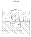
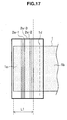
- FIG. 15 to FIG. 17 are explanatory diagrams showing states of the vicinity of the trapezoidal bead 2a in a case of performing the stretch forming by using a die having the general trapezoidal beads 2a and 3a.
- FIG. 15 is perspective views showing the states before and after clamping the blank 1 by the die 2 and the blank holder 3.
- FIG. 16 is a sectional view showing the vicinity of the trapezoidal beads 2a and 3 a including the clamp target part 1a, the outer peripheral part 1c and the trim line 1d of the blank 1.
- FIG. 17 is a top view showing the vicinity of the trapezoidal beads 2a and 3a including the clamp target part 1a, the outer peripheral part 1c and the trim line 1d of the blank 1. Incidentally, in FIG. 15 to FIG.
- a region of a length L1 is a bead corresponding part of the blank 1 to be clamped by the beads 2a and 3a and is a part to be generally discarded.
- the trapezoidal beads 2a and 3a are adapted to obtain a blank clamping force which is sufficient for the stretch forming by causing the bending and unbending deformation resistance of four trapezoidal corner parts 2a-1, 2a-2, 3a-1, and 3a-2 to generate.
- mass forming it is necessary to make the length of a sectional straight side part 2a-3 long to some extent in order not to destroy the trapezoidal bead 2a and in order to cause the bending and unbending deformation resistance of the trapezoidal corner parts 2a-1 and 2a-2 to be generated independently in the respective corner parts. Accordingly, the pressing length L1 of the trapezoidal beads 2a and 3a in a direction orthogonal to the trim line 1d becomes inevitably long. Therefore, it is difficult to shorten the pressing length L1 and to miniaturize the blank 1 with the trapezoidal beads 2a and 3a.
- Patent Literature 1 there is disclosed a drawing method of, in a drawing apparatus which is provided with a die, a punch and a blank holder, drawing a material in a state of holding the material by the blank holder and a facing die in which draw beads having continuous bead parts that are non-parallel to a line parallel to a drawing profile of the material are formed on wrinkle pressing surfaces.
- Patent Literature 2 there is disclosed a drawing method of, in a drawing apparatus which is provided with a die, a punch and a blank holder, providing a movable die face which configures a die face part and is movable relative to a die body and a movable blank holder which faces the movable die face and is movable relative to a blank holder body, making the movable die face and the movable blank holder freely advance and retreat from the outside to the inside toward a forming depressed part in the die, driving the movable die face and the movable blank holder from the outside to the inside in association with pushing of the blank and thereby performing drawing in high yield such that a shock line does not enter a product part.
- Patent Literature 3 there is disclosed a press die device which performs drawing and stretching by forming a bead on one die and forming a bead containing part for containing the bead in a part facing the bead on another die, wherein step parts individual protruding heights of which are gradually reduced laterally are provided on a leading end of the bead, stepped depressed parts which correspond to the step parts are provided in the bead containing part, unevenness which corresponds to the step parts in a case where a blank material is nipped and held between the both is formed on an edge of the blank material and thereby generation of wrinkles can be prevented even in a case of being applied to a press machine having a low load capacity.
- Patent Literature 4 there is disclosed a bead to be provided on a wrinkle pressing surface of a draw die, the draw bead being configured by a vertical wall part and a corrugated part which is formed to be consecutive to the vertical wall part and is corrugated in section.
- Patent Literature 1 is the one which intends to lock the material such that the material does not flow from the outside of the bead into the inside of the bead by using the beads which are trapezoidal in section and are corrugated in top view.
- the blank is clamped with the deformation resistance of bending and unbending deformation of the trapezoidal corner part, a surface pressure of the bead relative to the blank and expansion/contraction deformation resistance according to the corrugated shape.
- the method described in Patent Literature 1 may increase bead passing resistance of the material by extending the material up to a region outside a part which is clamped by the bead. Accordingly, the method described in Patent Literature 1 cannot improve the material yield due to an increase in parts which are cut off along the drawing profile and discarded.
- Patent Literature 2 is the one which targets on drawing which involves flowing of the material although aiming to improve the yield of material. Accordingly, the method described in Patent Literature 2 cannot improve the yield of material in the stretch forming which does not involve flowing of the material.
- Patent Literature 3 cannot improve the yield of material in the stretch forming because the bead length in the direction which is orthogonal to the material flowing direction is inevitably increased.
- Patent Literature 4 Although the draw bead described in Patent Literature 4 is the bead which aims to improve the yield of steel material by suppressing flowing-in of the material, it purports a draw bead to be used in the drawing. Accordingly, the draw bead described in Patent Literature 4 is not the one which improves the yield of material by preventing flowing-in of the material in lock beads to be used in the stretch forming.
- the present invention has been made in view of the above mentioned problems and an object of the present invention is to provide a manufacturing apparatus and a manufacturing method for a stretch-formed product which can improve the yield of material in the stretch forming performed while clamping the blank by the lock beads.
- a manufacturing apparatus for a stretch-formed product including: a die and a blank holder which have clamping surfaces facing each other; a punch that, in a state where a margin of a blank of a sheet material is clamped by the clamping surfaces of the die and the blank holder, relatively presses a forming region of the blank into the die and thereby performs stretch forming on the forming region of the blank; and lock beads that are provided on the clamping surfaces of the die and the blank holder in mutually similar shapes and have first surfaces, second surfaces that intersect with the first surfaces, and third surfaces that intersect with the second surfaces from outer edges toward the centers of the die and the blank holder, the first surfaces each having a plurality of depression-protrusion parts.
- the plurality of depression-protrusion parts When the plurality of depression-protrusion parts are viewed from the outer edge toward the center of the die or the blank holder, the plurality of depression-protrusion parts may have any shape of a trapezoidal shape, a rectangular shape and a triangular shape or a combined shape thereof.
- the plurality of depression-protrusion parts may each have a fourth surface and a fifth surface intersecting with each other, the fourth surface and the fifth surface may intersect with the second surface, and at least one of the fourth surface and the fifth surface may intersect with the first surface.
- the plurality of depression-protrusion parts may each have the fourth surface and a sixth surface facing each other and the fifth surface that intersects with the fourth surface and the sixth surface, the fourth surface, the fifth surface and the sixth surface may intersect with the second surface, and at least one of the fourth surface, the fifth surface and the sixth surface may intersect with the first surface.
- a pitch interval of the plurality of depression-protrusion parts when the triangular shape is defined as one pitch may be within a range of 5 to 50 mm, and a rising angle of a surface of the depression-protrusion part may be within a range of 10 to 40 degrees.
- a pitch interval of the plurality of depression-protrusion parts when a set of a protruded shape and a depressed shape is defined as one pitch may be within a range of 5 to 50 mm and a height of the depression-protrusion part may be within a range of 1.0 to 10.0 mm.
- a manufacturing method for a stretch-formed product including a step of clamping a margin of a blank of a sheet material by the clamping surfaces of the die and the blank holder which are provided with lock beads which have first surfaces, second surfaces which intersect with the first surfaces and third surfaces which intersect with the second surfaces from outer edges toward the centers of the die and the blank holder at positions corresponding to the margin of the blank of the sheet material, the first surfaces each having a plurality of depression-protrusion parts, and the lock beads being provided in mutually similar shapes, and a step of stretch-forming the blank by pressing a forming region of the blank toward the die by a punch in a state of clamping the margin of the blank by the die and the blank holder.
- the yield of material in the stretch forming performed while clamping the blank by the lock beads can be improved.
- FIG. 1 is a schematic explanatory diagram showing a configuration of a manufacturing apparatus 10 for a stretch-formed product according to the present embodiment.
- FIG. 1 is a perspective view showing the manufacturing apparatus 10 by partially omitting and simplifying it.
- the manufacturing apparatus 10 has a die 11, a blank holder 12, and a punch 13.
- the contour of a blank 14 is shown by a two-dot chain line.
- the die 11 has a clamping surface 11 a which clamps the blank 14.
- the clamping surface 11 a has a punch containing part in which the punch 13 is to be contained when forming, and a wedge-shaped bead 15 which is provided along the outside of a margin of the blank 14.
- the wedge-shaped bead 15 is one form of the lock bead.
- the die 11 and the wedge-shaped bead 15 are shown by being simplified by a one-dot chain line. Details of the wedge-shaped bead 15 will be described later with reference to FIG. 2 .
- the punch containing part is omitted in FIG. 1 .
- the blank 14 is located at the center and has a forming region 14b corresponding to a part which will become a product (in the example in FIG. 1 , a rear door outer panel), a clamp target part 14a to be clamped by the die 11 and the blank holder 12 and a trim line 14d.
- the clamp target part 14a and the outer peripheral part 14c are cut off along the trim line 14d and are discarded.
- the trim line 14d is omitted.
- the wedge-shaped bead 15 may be arranged on the entire circumference of the blank 14.
- the wedge-shaped bead 15 may be arranged only on the part to be subjected to the stretch forming.
- various types of known draw beads for the drawing can be provided on the part to be subjected to the drawing.
- the blank holder 12 and the punch 13 may be the same as the materials and functions which are known as those of dies, blank holders and punches of this type, and are well known to a person skilled in the art, further description on the die 11, the blank holder 12 and the punch 13 is omitted.
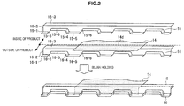
- FIG. 2 to FIG. 4 are explanatory diagrams showing the states of the wedge-shaped beads 15 and 16 at the time of stretch forming.
- FIG. 2 is a perspective view showing the states before and after clamping the blank 14.
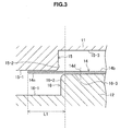
- FIG. 3 is a sectional view showing the wedge-shaped beads 15 and 16, and the outer peripheral part 14c and the trim line 14d of the blank 14.
- FIG. 4 is a top view showing the wedge-shaped bead 15, and the outer peripheral part 14c and the trim line 14d of the blank 14.
- a region of the length L1 is a part to be clamped by the wedge-shaped beads 15 and 16 and to be discarded in most cases.
- the wedge-shaped bead 15 provided on the die 11 will be mainly described. Since the wedge-shaped bead 16 provided on the blank holder 12 corresponds to the wedge-shaped bead 15 in position and shape, it can be understood by reading it through appropriate alteration.
- the first surface 15-1 of the wedge-shaped bead 15 has a plurality of depression-protrusion parts each configured by a fourth surface 15-4, a fifth surface 15-5 and a sixth surface 15-6.
- the fifth surface 15-5 intersects with the fourth surface 15-4.
- the sixth surface 15-6 intersects with the fifth surface 15-5 and faces the fourth surface 15-4. That is, the fourth surface 15-4 and the sixth surface 15-6 face each other.
- the height and pitch of this quadrilateral, the rising angles of the fourth surface 15-4 and the sixth surface 15-6, and the radius of curvature of a corner part that the fourth surface 15-4 or the sixth surface 15-6 and the fifth surface 15-5 make can be appropriately set.
- the height of the quadrilateral is too low or the pitch is too large, it becomes difficult to obtain an effect of increasing the deformation resistance (hereinafter, also referred to as the "unbending deformation resistance") caused when the depressed and protruded shapes are unbent to planar shapes, and the blank clamping force is lowered in some cases.
- the height of the quadrilateral is too high, it is feared that the blank 14 may be destroyed when clamping the blank 14.
- the rising angles of the fourth surface 15-4 and the sixth surface 15-6 are too small, it becomes difficult to obtain the effect of increasing the unbending deformation resistance, and the blank clamping force is lowered in some cases.
- an interval per pitch that a protruded shape and a depressed shape of the quadrilateral are defined as one set be within a range of 5 to 50 mm and the height of the quadrilateral be within a range of 1.0 to 10.0 mm.
- the level difference when in relation to the height of the second surface 15-2, a level difference between the third surface 15-3 and the fifth surface 15-5 is too small, bending deformation of the blank 14 on the depression-protrusion part and bending deformation at the boundary between the second surface 15-2 and the third surface 15-3 cannot be individually generated and it is feared that the effect of increasing the unbending deformation resistance may not be obtained.
- the level difference when the level difference is too large, it is feared that the material yield of the blank 14 may be lowered. Accordingly, it is preferable that the level difference be within a range of 1.5 to 8.0 mm.
- a fourth surface 16-4, a fifth surface 16-5 and a sixth surface 16-6 of the wedge-shaped bead 16 provided on the blank holder 12 are arranged at positions respectively corresponding to the fourth surface 15-4, the fifth surface 15-5 and the sixth surface 15-6 of the wedge-shaped bead 15 provided on the die 11. Accordingly, in a state of clamping the blank 14 by the die 11 and the blank holder 12, the fourth surface 15-4, the fifth surface 15-5 and the sixth surface 15-6 of the wedge-shaped bead 15 respectively face the fourth surface 16-4, the fifth surface 16-5 and the sixth surface 16-6 of the wedge-shaped bead 16 via the blank 14.
- the wedge-shaped bead 15, 16 has a stepped shape in which the first surface 15-1, 16-1 is located lower than the third surface 15-3, 16-3 has been taken by way of example, the stepped shape may be reversed. That is, the wedge-shaped bead 15, 16 may have a stepped shape in which the first surface 15-1, 16-1 is located higher than the third surface 15-3, 16-3.
- FIG. 5 to FIG. 7 are explanatory diagrams showing other wedge-shaped beads 17 and 18 used in the stretch forming as a modified example of the lock bead.
- FIG. 5 is a perspective view showing the states before and after clamping the blank 14.
- FIG. 6 is a sectional view showing the wedge-shaped beads 17 and 18, and the outer peripheral part 14c and the trim line 14d of the blank 14.
- FIG. 7 is a top view showing the wedge-shaped bead 17, and the outer peripheral part 14c and the trim line 14d of the blank 14.
- a region of the length L1 is a part to be clamped by the wedge-shaped beads 17 and 18 and to be discarded in most cases.
- the wedge-shaped bead 17 provided on the die 11 will be mainly described later. Since the wedge-shaped bead 18 provided on the blank holder 12 also corresponds to the wedge-shaped bead 17 in position and shape in this example, it can be understood by reading it through appropriate alteration.
- the wedge-shaped bead 17 has a stepped shape including a first surface 17-1, a second surface 17-2 and a third surface 17-3 from the outer edge toward the center of the die 11 (from the left side to the right side in FIG. 6 ). That is, the first surface 17-1, the second surface 17-2 and the third surface 17-3 make a step from the outer edges toward the centers of the blank holder 12 and the die 11.
- the second surface 17-2 intersects with (in the shown example, is orthogonal to) the first surface 17-1.
- the third surface 17-3 intersects with (in the shown example, is orthogonal to) the second surface 17-2.
- the first surface 17-1 of the wedge-shaped bead 17 has a plurality of depression-protrusion parts in which a fourth surface 17-4 and a fifth surface 17-5 are alternately and continuously formed in an extending direction of the wedge-shaped bead 17, that is in the direction orthogonal to the direction going from the outer edge toward the center of the die 11.
- depressed and protruded shapes are alternately arrayed on the first surface 17-1 in the extending direction of the wedge-shaped bead 17.
- the fourth surface 17-4 and the fifth surface 17-5 of the wedge-shaped bead 17 form two sides of a triangle.
- the height and pitch of this triangle, the rising angles of the fourth surface 17-4 and the fifth surface 17-5, and the radius of curvature of a corner part that the fourth surface 17-4 and the fifth surface 17-5 make can be appropriately set.
- the height of the triangle is too low or the pitch is too large, it becomes difficult to obtain the effect of increasing the unbending deformation resistance, and the blank clamping force is lowered in some cases.
- the rising angles of the fourth surface 17-4 and the fifth surface 17-5 are too small, the pitch of the triangle becomes large, and consequently it becomes difficult to obtain the effect of increasing the unbending deformation resistance and the blank clamping force is lowered in some cases.
- the rising angles of the fourth surface 17-4 and the fifth surface 17-5 are large and the height of the triangle becomes too high, it is feared that the blank 14 may be destroyed when clamping the blank 14 and wrinkles may be generated on the blank 14.
- a pitch interval of the triangle be within a range of 5 to 50 mm and the rising angles of the fourth surface 17-4 and the fifth surface 17-5 be within a range of 10 to 40 degrees.
- the pitch interval in a case of the triangular wedge shape means the length of the base of the triangle.
- the level difference when in relation to the height of the second surface 17-2, a level difference between the third surface 17-3 and the apex of the triangle is too small, bending deformation of the blank 14 on the depression-protrusion part and bending deformation at the boundary between the second surface 17-2 and the third surface 17-3 cannot be individually generated and it is feared that the effect of increasing the unbending deformation resistance may not be obtained.
- the level difference when the level difference is too large, it is feared that the material yield of the blank 14 may be lowered. Accordingly, it is preferable that the level difference be within a range of 1.5 to 8.0 mm.
- a fourth surface 18-4 and a fifth surface 18-5 of the wedge-shaped bead 18 provided on the blank holder 12 are arranged at positions respectively corresponding to the fourth surface 17-4 and the fifth surface 17-5 of the wedge-shaped bead 17 provided on the die 11. Accordingly, in a state of clamping the blank 14 by the die 11 and the blank holder 12, the fourth surface 18-4 and the fifth surface 18-5 of the wedge-shaped bead 18 respectively face the fourth surface 17-4 and the fifth surface 17-5 of the wedge-shaped bead 17 via the blank 14.
- a known process of the stretch forming can be adopted as the entire process of the stretch forming. Briefly describing, first, the blank 14 is aligned and placed on the blank holder 12. Then, the margin of the blank 14 is clamped by the clamping surfaces 11a and 12a of the die 11 and the blank holder 12 on which the wedge-shaped beads 15 and 16 are provided by relatively moving the die 11 toward the blank holder 12.
- the forming region 14b located at the center of the blank 14 is relatively pressed toward the die 11 by relatively moving the punch 13 toward the die 11 in this state.
- the clamp target part 14a of the blank 14 is clamped by the wedge-shaped beads 15 and 16 provided on the clamping surfaces 11 a and 12a such that the blank 14 does not flow from the outer edge part of the blank 14 toward the forming region 14b.
- the stretch-formed product with no flowing of the blank 14 into the forming region 14b is formed.
- the wedge-shaped bead 15, 16 has a stepped shape formed by the first surface 15-1, 16-1, the second surface 15-2, 16-2 and the third surface 15-3, 16-3 from the outer edge toward the center of each of the die 11 and the blank holder 12.
- the second surface 15-2, 16-2 intersects with the first surface 15-1, 16-1.
- the third surface 15-3, 16-3 intersects with the second surface 15-2, 16-2.
- the first surface 15-1, 16-1 has the fourth surface 15-4, 16-4 and sixth surface 15-6, 16-6 facing each other in the extending direction of the wedge-shaped bead 15, 16. Further, the first surface 15-1, 16-1 has the fifth surface 15-5, 16-5 which is arranged between the fourth surface 15-4, 16-4 and the sixth surface 15-6, 16-6 and intersects with the fourth surface 15-4, 16-4 and the sixth surface 15-6, 16-6.
- FIG. 9 is a graph showing a result of the evaluations.
- the locking force is indicated by a relative value with the locking force of the conventional trapezoidal beads 2a and 3a being set as 100%.
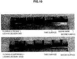
- the blank clamping performance (the blank locking force), the material yield, the appearance of the clamp target part and the influence on a product surface were each evaluated by drawing out the blank by using the chuck similarly to the Evaluation 1, while changing the shapes of the wedge-shaped beads 15 and 16 shown in FIG. 2 to FIG. 4 and the wedge-shaped beads 17 and 18 shown in FIG. 5 to FIG. 7 .
- the blank (the test material) used is the alloyed hot dip galvanized steel sheet which is 0.7 mm in sheet thickness and is the 340 MPa level in tensile strength measured in the tensile test based on JIS Z 2241 similarly to the Evaluation 1. Table 1 indicates the shapes of the wedge-shaped beads and evaluation results.
- the wedge wall angle means the rising angles of the fourth surfaces 15-4 and 16-4 and the sixth surfaces 15-6 and 16-6 in the case of the trapezoidal wedge shape, and means the rising angles of the fourth surfaces 17-4 and 18-4 and the fifth surfaces 17-5 and 18-5 in the case of the triangular wedge shape.
- the pitch interval is within a range of 5 to 50 mm and the wedge height is within a range of 1.0 to 10.0 mm, the locking force required for the stretch forming can be ensured and also the material yield of the blank can be improved.
- the Comparative examples 8, 9, 11, and 12 in which the wedge wall angle is 4 degrees or 6 degrees have lowered locking performance and it was not possible to ensure the locking force required for the stretch forming.
- the Comparative example 10 in which the wedge height is 10.0 mm the wedge wall angle reached 45 degrees, the blank of the clamp target part was destroyed, the wrinkles were generated on the blank, the locking force could not be evaluated and also the material yield was lowered.
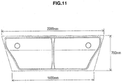
- the pressing length L1 of the clamp target part of the blank to be clamped by each lock bead was 9.5 mm in the Example and 19.0 mm in the Comparative example. Consequently, while the area of the blank in the Example was about 1.372 m 2 , the area of the blank in the Comparative example was 1.425 m 2 . Accordingly, in the case where the wedge-shaped beads of the Example were used, the yield of material in the stretch forming was improved by about 4% in comparison with the case where the trapezoidal beads of the Comparative example were used. At present, improvement of the yield of material in the stretch forming is in a situation that it almost reaches its limit and it is an extremely noticeable effect that the yield of the material can be improved by about 4%.
Landscapes
- Engineering & Computer Science (AREA)
- Mechanical Engineering (AREA)
- Shaping Metal By Deep-Drawing, Or The Like (AREA)
Applications Claiming Priority (2)
| Application Number | Priority Date | Filing Date | Title |
|---|---|---|---|
| JP2013269853 | 2013-12-26 | ||
| PCT/JP2014/082664 WO2015098519A1 (ja) | 2013-12-26 | 2014-12-10 | 張出し成形品の製造装置及び製造方法 |
Publications (3)
| Publication Number | Publication Date |
|---|---|
| EP3088094A1 true EP3088094A1 (de) | 2016-11-02 |
| EP3088094A4 EP3088094A4 (de) | 2017-08-09 |
| EP3088094B1 EP3088094B1 (de) | 2021-09-29 |
Family
ID=53478383
Family Applications (1)
| Application Number | Title | Priority Date | Filing Date |
|---|---|---|---|
| EP14873861.0A Active EP3088094B1 (de) | 2013-12-26 | 2014-12-10 | Herstellungsvorrichtung und herstellungsverfahren für durch dehnung geformte produkte |
Country Status (10)
| Country | Link |
|---|---|
| US (1) | US10071410B2 (de) |
| EP (1) | EP3088094B1 (de) |
| JP (1) | JP6094689B2 (de) |
| KR (2) | KR20160088345A (de) |
| CN (1) | CN105828969A (de) |
| CA (1) | CA2931281C (de) |
| MX (1) | MX376391B (de) |
| MY (1) | MY178533A (de) |
| RU (1) | RU2666805C2 (de) |
| WO (1) | WO2015098519A1 (de) |
Families Citing this family (3)
| Publication number | Priority date | Publication date | Assignee | Title |
|---|---|---|---|---|
| EP4011517B1 (de) * | 2019-08-06 | 2025-07-09 | Nippon Steel Corporation | Verfahren zur herstellung eines pressgeformten artikels |
| KR102448247B1 (ko) | 2021-02-18 | 2022-09-29 | 한국항공우주산업 주식회사 | 항공기 부품 성형 장치 |
| JP7789251B1 (ja) * | 2025-05-14 | 2025-12-19 | 株式会社ジーテクト | プレス装置および同プレス装置を用いた板材の加工方法 |
Family Cites Families (18)
| Publication number | Priority date | Publication date | Assignee | Title |
|---|---|---|---|---|
| JPH0237921A (ja) * | 1988-07-26 | 1990-02-07 | Nissan Motor Co Ltd | プレス成形方法 |
| RU1584221C (ru) | 1988-12-28 | 1994-09-30 | АвтоВАЗ | Штамп для листовой штамповки |
| JP2950026B2 (ja) * | 1992-06-17 | 1999-09-20 | トヨタ自動車株式会社 | 絞り加工方法 |
| JPH08267154A (ja) | 1995-03-31 | 1996-10-15 | Suzuki Motor Corp | プレス用金型装置 |
| JP2977071B2 (ja) | 1995-07-24 | 1999-11-10 | トヨタ自動車株式会社 | 絞り成形方法および絞り成形型 |
| JP3727402B2 (ja) | 1996-02-27 | 2005-12-14 | 本田技研工業株式会社 | 絞り成形装置 |
| US6196043B1 (en) * | 1999-08-27 | 2001-03-06 | General Motors Corporation | Double vee lockbead for sheet metal forming |
| JP2003164922A (ja) * | 2001-12-03 | 2003-06-10 | Toyota Motor Corp | プレス型 |
| JP3931736B2 (ja) * | 2002-06-07 | 2007-06-20 | 株式会社豊田自動織機 | プレス成形型 |
| JP4853007B2 (ja) * | 2004-12-27 | 2012-01-11 | 日産自動車株式会社 | プレス成形型 |
| JP2007245188A (ja) * | 2006-03-15 | 2007-09-27 | Kanto Auto Works Ltd | 絞りビード及びプレス成形方法 |
| CN101683672A (zh) | 2008-09-23 | 2010-03-31 | 比亚迪股份有限公司 | 一种板件的拉延方法 |
| JP5217928B2 (ja) | 2008-11-12 | 2013-06-19 | 新日鐵住金株式会社 | プレス加工方法及びプレス成形体 |
| JP5557374B2 (ja) * | 2010-01-22 | 2014-07-23 | ダイハツ工業株式会社 | プレス成形金型 |
| JP5689726B2 (ja) * | 2011-03-31 | 2015-03-25 | 新日鐵住金株式会社 | 張り出し成形品の製造装置および製造方法 |
| US9149854B2 (en) | 2011-05-04 | 2015-10-06 | Fca Us Llc | Stamping apparatus |
| JP5917952B2 (ja) * | 2012-03-02 | 2016-05-18 | トヨタ自動車株式会社 | プレス成形装置 |
| US9592544B2 (en) * | 2012-12-26 | 2017-03-14 | Nissan Motor Co., Ltd. | Draw forming method |
-
2014
- 2014-12-10 MY MYPI2016701931A patent/MY178533A/en unknown
- 2014-12-10 KR KR1020167015882A patent/KR20160088345A/ko not_active Ceased
- 2014-12-10 EP EP14873861.0A patent/EP3088094B1/de active Active
- 2014-12-10 WO PCT/JP2014/082664 patent/WO2015098519A1/ja not_active Ceased
- 2014-12-10 KR KR1020187013632A patent/KR102174261B1/ko active Active
- 2014-12-10 CN CN201480068739.4A patent/CN105828969A/zh active Pending
- 2014-12-10 US US15/038,941 patent/US10071410B2/en active Active
- 2014-12-10 MX MX2016007456A patent/MX376391B/es active IP Right Grant
- 2014-12-10 CA CA2931281A patent/CA2931281C/en not_active Expired - Fee Related
- 2014-12-10 RU RU2016123936A patent/RU2666805C2/ru not_active IP Right Cessation
- 2014-12-10 JP JP2015554727A patent/JP6094689B2/ja active Active
Also Published As
| Publication number | Publication date |
|---|---|
| JPWO2015098519A1 (ja) | 2017-03-23 |
| WO2015098519A1 (ja) | 2015-07-02 |
| MX2016007456A (es) | 2016-09-08 |
| EP3088094A4 (de) | 2017-08-09 |
| RU2666805C2 (ru) | 2018-09-12 |
| KR20160088345A (ko) | 2016-07-25 |
| MX376391B (es) | 2025-03-07 |
| US20170001232A1 (en) | 2017-01-05 |
| CN105828969A (zh) | 2016-08-03 |
| CA2931281C (en) | 2017-11-28 |
| KR102174261B1 (ko) | 2020-11-04 |
| JP6094689B2 (ja) | 2017-03-15 |
| CA2931281A1 (en) | 2015-07-02 |
| US10071410B2 (en) | 2018-09-11 |
| KR20180055919A (ko) | 2018-05-25 |
| RU2016123936A (ru) | 2018-01-31 |
| MY178533A (en) | 2020-10-15 |
| EP3088094B1 (de) | 2021-09-29 |
Similar Documents
| Publication | Publication Date | Title |
|---|---|---|
| CN109414745B (zh) | 冲压部件的制造方法及制造装置 | |
| CN104870118B (zh) | 冲压部件、其制造方法以及制造装置 | |
| EP3031545B1 (de) | Pressgeformtes produkt, herstellungsverfahren für pressgeformtes produkt | |
| CN105792957B (zh) | 压制成型装置、使用了该成型装置的压制成型品的制造方法以及压制成型品 | |
| US10124387B2 (en) | Press-molded product, press-molded product producing method, and press-molded product producing apparatus | |
| CN103237611A (zh) | L形产品的制造方法 | |
| WO2014050973A1 (ja) | センターピラーリンフォースメントの製造方法 | |
| EP3088094B1 (de) | Herstellungsvorrichtung und herstellungsverfahren für durch dehnung geformte produkte | |
| CN115283568B (zh) | 板材转向托架成型工艺及连续模 | |
| US20200206798A1 (en) | Method for manufacturing press molded product | |
| JP6712218B2 (ja) | 自動車のドアビーム | |
| JP7006666B2 (ja) | プレス成形品の設計方法、プレス成形品およびプレス成形品の製造方法 | |
| CN115889555A (zh) | 成型装置及使用该成型装置的成型方法 | |
| CN105246610B (zh) | 用于热成型薄的半成品的方法 | |
| JP2008100267A (ja) | パネル部材の成形方法 | |
| JP6872423B2 (ja) | プレス装置 | |
| KR20110071694A (ko) | 굴삭기 캐빈용 골조 파이프의 성형 방법, 굴삭기 캐빈의 제조 방법 및 굴삭기 캐빈 골조 |
Legal Events
| Date | Code | Title | Description |
|---|---|---|---|
| PUAI | Public reference made under article 153(3) epc to a published international application that has entered the european phase |
Free format text: ORIGINAL CODE: 0009012 |
|
| 17P | Request for examination filed |
Effective date: 20160613 |
|
| AK | Designated contracting states |
Kind code of ref document: A1 Designated state(s): AL AT BE BG CH CY CZ DE DK EE ES FI FR GB GR HR HU IE IS IT LI LT LU LV MC MK MT NL NO PL PT RO RS SE SI SK SM TR |
|
| AX | Request for extension of the european patent |
Extension state: BA ME |
|
| DAX | Request for extension of the european patent (deleted) | ||
| A4 | Supplementary search report drawn up and despatched |
Effective date: 20170706 |
|
| RIC1 | Information provided on ipc code assigned before grant |
Ipc: B21D 25/04 20060101AFI20170630BHEP Ipc: B21D 24/04 20060101ALI20170630BHEP |
|
| RAP1 | Party data changed (applicant data changed or rights of an application transferred) |
Owner name: NIPPON STEEL CORPORATION |
|
| STAA | Information on the status of an ep patent application or granted ep patent |
Free format text: STATUS: EXAMINATION IS IN PROGRESS |
|
| 17Q | First examination report despatched |
Effective date: 20201012 |
|
| REG | Reference to a national code |
Ref country code: DE Ref legal event code: R079 Ref document number: 602014080440 Country of ref document: DE Free format text: PREVIOUS MAIN CLASS: B21D0025040000 Ipc: B21D0024040000 |
|
| GRAP | Despatch of communication of intention to grant a patent |
Free format text: ORIGINAL CODE: EPIDOSNIGR1 |
|
| STAA | Information on the status of an ep patent application or granted ep patent |
Free format text: STATUS: GRANT OF PATENT IS INTENDED |
|
| RIC1 | Information provided on ipc code assigned before grant |
Ipc: B21D 35/00 20060101ALI20210421BHEP Ipc: B21D 22/22 20060101ALI20210421BHEP Ipc: B21D 25/04 20060101ALI20210421BHEP Ipc: B21D 24/04 20060101AFI20210421BHEP |
|
| INTG | Intention to grant announced |
Effective date: 20210514 |
|
| GRAS | Grant fee paid |
Free format text: ORIGINAL CODE: EPIDOSNIGR3 |
|
| GRAA | (expected) grant |
Free format text: ORIGINAL CODE: 0009210 |
|
| STAA | Information on the status of an ep patent application or granted ep patent |
Free format text: STATUS: THE PATENT HAS BEEN GRANTED |
|
| AK | Designated contracting states |
Kind code of ref document: B1 Designated state(s): AL AT BE BG CH CY CZ DE DK EE ES FI FR GB GR HR HU IE IS IT LI LT LU LV MC MK MT NL NO PL PT RO RS SE SI SK SM TR |
|
| REG | Reference to a national code |
Ref country code: GB Ref legal event code: FG4D |
|
| REG | Reference to a national code |
Ref country code: CH Ref legal event code: EP Ref country code: AT Ref legal event code: REF Ref document number: 1433752 Country of ref document: AT Kind code of ref document: T Effective date: 20211015 |
|
| REG | Reference to a national code |
Ref country code: DE Ref legal event code: R096 Ref document number: 602014080440 Country of ref document: DE |
|
| REG | Reference to a national code |
Ref country code: IE Ref legal event code: FG4D |
|
| REG | Reference to a national code |
Ref country code: LT Ref legal event code: MG9D |
|
| PG25 | Lapsed in a contracting state [announced via postgrant information from national office to epo] |
Ref country code: FI Free format text: LAPSE BECAUSE OF FAILURE TO SUBMIT A TRANSLATION OF THE DESCRIPTION OR TO PAY THE FEE WITHIN THE PRESCRIBED TIME-LIMIT Effective date: 20210929 Ref country code: NO Free format text: LAPSE BECAUSE OF FAILURE TO SUBMIT A TRANSLATION OF THE DESCRIPTION OR TO PAY THE FEE WITHIN THE PRESCRIBED TIME-LIMIT Effective date: 20211229 Ref country code: LT Free format text: LAPSE BECAUSE OF FAILURE TO SUBMIT A TRANSLATION OF THE DESCRIPTION OR TO PAY THE FEE WITHIN THE PRESCRIBED TIME-LIMIT Effective date: 20210929 Ref country code: BG Free format text: LAPSE BECAUSE OF FAILURE TO SUBMIT A TRANSLATION OF THE DESCRIPTION OR TO PAY THE FEE WITHIN THE PRESCRIBED TIME-LIMIT Effective date: 20211229 Ref country code: HR Free format text: LAPSE BECAUSE OF FAILURE TO SUBMIT A TRANSLATION OF THE DESCRIPTION OR TO PAY THE FEE WITHIN THE PRESCRIBED TIME-LIMIT Effective date: 20210929 Ref country code: SE Free format text: LAPSE BECAUSE OF FAILURE TO SUBMIT A TRANSLATION OF THE DESCRIPTION OR TO PAY THE FEE WITHIN THE PRESCRIBED TIME-LIMIT Effective date: 20210929 Ref country code: RS Free format text: LAPSE BECAUSE OF FAILURE TO SUBMIT A TRANSLATION OF THE DESCRIPTION OR TO PAY THE FEE WITHIN THE PRESCRIBED TIME-LIMIT Effective date: 20210929 |
|
| REG | Reference to a national code |
Ref country code: NL Ref legal event code: MP Effective date: 20210929 |
|
| REG | Reference to a national code |
Ref country code: AT Ref legal event code: MK05 Ref document number: 1433752 Country of ref document: AT Kind code of ref document: T Effective date: 20210929 |
|
| PG25 | Lapsed in a contracting state [announced via postgrant information from national office to epo] |
Ref country code: LV Free format text: LAPSE BECAUSE OF FAILURE TO SUBMIT A TRANSLATION OF THE DESCRIPTION OR TO PAY THE FEE WITHIN THE PRESCRIBED TIME-LIMIT Effective date: 20210929 Ref country code: GR Free format text: LAPSE BECAUSE OF FAILURE TO SUBMIT A TRANSLATION OF THE DESCRIPTION OR TO PAY THE FEE WITHIN THE PRESCRIBED TIME-LIMIT Effective date: 20211230 |
|
| PG25 | Lapsed in a contracting state [announced via postgrant information from national office to epo] |
Ref country code: AT Free format text: LAPSE BECAUSE OF FAILURE TO SUBMIT A TRANSLATION OF THE DESCRIPTION OR TO PAY THE FEE WITHIN THE PRESCRIBED TIME-LIMIT Effective date: 20210929 |
|
| PG25 | Lapsed in a contracting state [announced via postgrant information from national office to epo] |
Ref country code: IS Free format text: LAPSE BECAUSE OF FAILURE TO SUBMIT A TRANSLATION OF THE DESCRIPTION OR TO PAY THE FEE WITHIN THE PRESCRIBED TIME-LIMIT Effective date: 20220129 Ref country code: SK Free format text: LAPSE BECAUSE OF FAILURE TO SUBMIT A TRANSLATION OF THE DESCRIPTION OR TO PAY THE FEE WITHIN THE PRESCRIBED TIME-LIMIT Effective date: 20210929 Ref country code: RO Free format text: LAPSE BECAUSE OF FAILURE TO SUBMIT A TRANSLATION OF THE DESCRIPTION OR TO PAY THE FEE WITHIN THE PRESCRIBED TIME-LIMIT Effective date: 20210929 Ref country code: PT Free format text: LAPSE BECAUSE OF FAILURE TO SUBMIT A TRANSLATION OF THE DESCRIPTION OR TO PAY THE FEE WITHIN THE PRESCRIBED TIME-LIMIT Effective date: 20220131 Ref country code: PL Free format text: LAPSE BECAUSE OF FAILURE TO SUBMIT A TRANSLATION OF THE DESCRIPTION OR TO PAY THE FEE WITHIN THE PRESCRIBED TIME-LIMIT Effective date: 20210929 Ref country code: NL Free format text: LAPSE BECAUSE OF FAILURE TO SUBMIT A TRANSLATION OF THE DESCRIPTION OR TO PAY THE FEE WITHIN THE PRESCRIBED TIME-LIMIT Effective date: 20210929 Ref country code: ES Free format text: LAPSE BECAUSE OF FAILURE TO SUBMIT A TRANSLATION OF THE DESCRIPTION OR TO PAY THE FEE WITHIN THE PRESCRIBED TIME-LIMIT Effective date: 20210929 Ref country code: EE Free format text: LAPSE BECAUSE OF FAILURE TO SUBMIT A TRANSLATION OF THE DESCRIPTION OR TO PAY THE FEE WITHIN THE PRESCRIBED TIME-LIMIT Effective date: 20210929 Ref country code: CZ Free format text: LAPSE BECAUSE OF FAILURE TO SUBMIT A TRANSLATION OF THE DESCRIPTION OR TO PAY THE FEE WITHIN THE PRESCRIBED TIME-LIMIT Effective date: 20210929 Ref country code: AL Free format text: LAPSE BECAUSE OF FAILURE TO SUBMIT A TRANSLATION OF THE DESCRIPTION OR TO PAY THE FEE WITHIN THE PRESCRIBED TIME-LIMIT Effective date: 20210929 |
|
| REG | Reference to a national code |
Ref country code: DE Ref legal event code: R097 Ref document number: 602014080440 Country of ref document: DE |
|
| PG25 | Lapsed in a contracting state [announced via postgrant information from national office to epo] |
Ref country code: MC Free format text: LAPSE BECAUSE OF FAILURE TO SUBMIT A TRANSLATION OF THE DESCRIPTION OR TO PAY THE FEE WITHIN THE PRESCRIBED TIME-LIMIT Effective date: 20210929 Ref country code: DK Free format text: LAPSE BECAUSE OF FAILURE TO SUBMIT A TRANSLATION OF THE DESCRIPTION OR TO PAY THE FEE WITHIN THE PRESCRIBED TIME-LIMIT Effective date: 20210929 |
|
| REG | Reference to a national code |
Ref country code: CH Ref legal event code: PL |
|
| PLBE | No opposition filed within time limit |
Free format text: ORIGINAL CODE: 0009261 |
|
| STAA | Information on the status of an ep patent application or granted ep patent |
Free format text: STATUS: NO OPPOSITION FILED WITHIN TIME LIMIT |
|
| GBPC | Gb: european patent ceased through non-payment of renewal fee |
Effective date: 20211229 |
|
| 26N | No opposition filed |
Effective date: 20220630 |
|
| REG | Reference to a national code |
Ref country code: BE Ref legal event code: MM Effective date: 20211231 |
|
| PG25 | Lapsed in a contracting state [announced via postgrant information from national office to epo] |
Ref country code: LU Free format text: LAPSE BECAUSE OF NON-PAYMENT OF DUE FEES Effective date: 20211210 Ref country code: IE Free format text: LAPSE BECAUSE OF NON-PAYMENT OF DUE FEES Effective date: 20211210 Ref country code: GB Free format text: LAPSE BECAUSE OF NON-PAYMENT OF DUE FEES Effective date: 20211229 |
|
| PG25 | Lapsed in a contracting state [announced via postgrant information from national office to epo] |
Ref country code: SI Free format text: LAPSE BECAUSE OF FAILURE TO SUBMIT A TRANSLATION OF THE DESCRIPTION OR TO PAY THE FEE WITHIN THE PRESCRIBED TIME-LIMIT Effective date: 20210929 Ref country code: BE Free format text: LAPSE BECAUSE OF NON-PAYMENT OF DUE FEES Effective date: 20211231 |
|
| PG25 | Lapsed in a contracting state [announced via postgrant information from national office to epo] |
Ref country code: LI Free format text: LAPSE BECAUSE OF NON-PAYMENT OF DUE FEES Effective date: 20211231 Ref country code: CH Free format text: LAPSE BECAUSE OF NON-PAYMENT OF DUE FEES Effective date: 20211231 |
|
| PG25 | Lapsed in a contracting state [announced via postgrant information from national office to epo] |
Ref country code: IT Free format text: LAPSE BECAUSE OF FAILURE TO SUBMIT A TRANSLATION OF THE DESCRIPTION OR TO PAY THE FEE WITHIN THE PRESCRIBED TIME-LIMIT Effective date: 20210929 |
|
| PG25 | Lapsed in a contracting state [announced via postgrant information from national office to epo] |
Ref country code: HU Free format text: LAPSE BECAUSE OF FAILURE TO SUBMIT A TRANSLATION OF THE DESCRIPTION OR TO PAY THE FEE WITHIN THE PRESCRIBED TIME-LIMIT; INVALID AB INITIO Effective date: 20141210 |
|
| PG25 | Lapsed in a contracting state [announced via postgrant information from national office to epo] |
Ref country code: CY Free format text: LAPSE BECAUSE OF FAILURE TO SUBMIT A TRANSLATION OF THE DESCRIPTION OR TO PAY THE FEE WITHIN THE PRESCRIBED TIME-LIMIT Effective date: 20210929 |
|
| PG25 | Lapsed in a contracting state [announced via postgrant information from national office to epo] |
Ref country code: SM Free format text: LAPSE BECAUSE OF FAILURE TO SUBMIT A TRANSLATION OF THE DESCRIPTION OR TO PAY THE FEE WITHIN THE PRESCRIBED TIME-LIMIT Effective date: 20210929 |
|
| PG25 | Lapsed in a contracting state [announced via postgrant information from national office to epo] |
Ref country code: MK Free format text: LAPSE BECAUSE OF FAILURE TO SUBMIT A TRANSLATION OF THE DESCRIPTION OR TO PAY THE FEE WITHIN THE PRESCRIBED TIME-LIMIT Effective date: 20210929 |
|
| PG25 | Lapsed in a contracting state [announced via postgrant information from national office to epo] |
Ref country code: TR Free format text: LAPSE BECAUSE OF FAILURE TO SUBMIT A TRANSLATION OF THE DESCRIPTION OR TO PAY THE FEE WITHIN THE PRESCRIBED TIME-LIMIT Effective date: 20210929 |
|
| PG25 | Lapsed in a contracting state [announced via postgrant information from national office to epo] |
Ref country code: MT Free format text: LAPSE BECAUSE OF FAILURE TO SUBMIT A TRANSLATION OF THE DESCRIPTION OR TO PAY THE FEE WITHIN THE PRESCRIBED TIME-LIMIT Effective date: 20210929 |
|
| PGFP | Annual fee paid to national office [announced via postgrant information from national office to epo] |
Ref country code: DE Payment date: 20251028 Year of fee payment: 12 |
|
| PGFP | Annual fee paid to national office [announced via postgrant information from national office to epo] |
Ref country code: FR Payment date: 20251110 Year of fee payment: 12 |