EP3088115A1 - Procede et dispositif de fabrication d'une pieces usinee - Google Patents
Procede et dispositif de fabrication d'une pieces usinee Download PDFInfo
- Publication number
- EP3088115A1 EP3088115A1 EP16000951.0A EP16000951A EP3088115A1 EP 3088115 A1 EP3088115 A1 EP 3088115A1 EP 16000951 A EP16000951 A EP 16000951A EP 3088115 A1 EP3088115 A1 EP 3088115A1
- Authority
- EP
- European Patent Office
- Prior art keywords
- reactor
- tool
- starting material
- reactor space
- electrolyte
- Prior art date
- Legal status (The legal status is an assumption and is not a legal conclusion. Google has not performed a legal analysis and makes no representation as to the accuracy of the status listed.)
- Granted
Links
Images
Classifications
-
- B—PERFORMING OPERATIONS; TRANSPORTING
- B23—MACHINE TOOLS; METAL-WORKING NOT OTHERWISE PROVIDED FOR
- B23H—WORKING OF METAL BY THE ACTION OF A HIGH CONCENTRATION OF ELECTRIC CURRENT ON A WORKPIECE USING AN ELECTRODE WHICH TAKES THE PLACE OF A TOOL; SUCH WORKING COMBINED WITH OTHER FORMS OF WORKING OF METAL
- B23H3/00—Electrochemical machining, i.e. removing metal by passing current between an electrode and a workpiece in the presence of an electrolyte
- B23H3/10—Supply or regeneration of working media
-
- B—PERFORMING OPERATIONS; TRANSPORTING
- B23—MACHINE TOOLS; METAL-WORKING NOT OTHERWISE PROVIDED FOR
- B23H—WORKING OF METAL BY THE ACTION OF A HIGH CONCENTRATION OF ELECTRIC CURRENT ON A WORKPIECE USING AN ELECTRODE WHICH TAKES THE PLACE OF A TOOL; SUCH WORKING COMBINED WITH OTHER FORMS OF WORKING OF METAL
- B23H9/00—Machining specially adapted for treating particular metal objects or for obtaining special effects or results on metal objects
- B23H9/14—Making holes
Definitions
- the invention relates to a method according to the preamble of claim 1 and an apparatus suitable for carrying it out according to the preamble of claim 2.
- Electrochemical ablation also known as ECM (Electro Chemical Machining) is an abrasive manufacturing process, especially for very hard materials.
- ECM Electrochemical Machining
- the electrochemical removal associated with the separation is suitable for simple deburring up to the production of complicated spatial forms.
- ECM Pulsed Electrochemical Machining
- PEM Pulsed Electrochemical Machining
- Electrochemical removal takes place without contact without mechanical contact between the tool and the workpiece. Thus, no mechanical forces are transmitted and material properties, such as hardness or toughness, have no influence on the process. However, properties such as melting point, heat and electrical conductivity of the starting material are important.
- the workpiece is positively polarized as the anode and the tool is negatively polarized as the cathode.
- an external voltage source serves to generate a current flow required for electrochemical removal.
- the shape of the tool poled as a cathode predetermines the shape of the workpiece. Electrochemical removal is therefore an imaging process. Due to the process, no wear occurs on the tool. A gap must be set between the tool and the workpiece depending on the electrical parameters and the flow conditions of the electrolyte.
- the gap width is 0.05 mm to 1 mm.
- the charge transport in the working gap takes over an electrolyte solution, such as an aqueous solution of sodium chloride (NaCl, saline) or sodium nitrate (NaNO 3 ).
- an electrolyte solution such as an aqueous solution of sodium chloride (NaCl, saline) or sodium nitrate (NaNO 3 ).
- NaCl, saline sodium chloride
- NaNO 3 sodium nitrate
- the resulting electron current dissolves metal ions from the workpiece.
- the dissolved metal ions then undergo reactions at the anode with portions of the cleaved electrolyte.
- the electrolyte residue reacts with water.
- the final product is metal hydroxide, which settles as sludge and must be removed.
- the fringes are not affected.
- the electrochemical removal is the only separating process without edge zone influence dar.
- the specific removal is 1 - 2.5 mm 3 /A.min.
- the lowering speed is variable and is between 0 and up to 20 mm / min.
- the electrolyte may be treated by centrifugation to separate the metal hydroxides from the electrolyte solution.
- the resulting sludge is further dewatered with filter presses to be disposed of as hazardous waste.
- electrolyte an electrically conductive liquid
- electrolyte an electrically conductive liquid
- the starting material is connected as an anode and an electrode serving as a tool is poled as a cathode.
- a method for producing at least one recess with an undercut in an electrically conductive body is known.
- a platelet-shaped electrode is moved into the body.
- a second electrochemical removal of material from the body takes place during movement of the electrode in a second movement section different from the first, wherein the second removal substantially at a first larger second distance around the electrode while supplying a current with respect to the first larger second current.
- an electrode for electrochemical removal comprises an electrode body on which electrically conductive structures are arranged, which are each separated by an electrically insulating layer.
- the electrode body consists of at least two electrically conductive components, between which an electrically insulating component is arranged.
- a first subject of the invention accordingly relates to a method for producing a workpiece by electrochemically removing a starting material, for example a semifinished product.
- the method provides to form a reactor space between a previously formed surface of the starting material, a hollow cylindrical reactor sleeve and a tool.
- the method further provides for equipping one of the side of the tool, which is opposite to the surface of the starting material which has hitherto been formed, and which faces the material to be treated, with a negative mold of the workpiece to be produced.
- the method also provides that the normal to the previously formed surface of the starting material, for example, vertically movable in the hollow cylindrical reactor sleeve arranged tool during the electrochemical removal at a constant distance to the receding with increasing electrochemical ablation surface of the starting material is held in the hollow cylindrical reactor sleeve.
- the method further provides for purging the reactor space during the electrochemical removal.
- the reactor space has an inlet and an outlet opening for the passage of an electrolyte during the electrochemical ablation on.
- the reactor space may be part of a closed circuit in which an electrolyte circulates during the electrochemical removal.
- the electrolyte thus preferably circulates in a closed circuit, part of which is the reactor space with its inlet and outlet opening.
- the method also provides that in the reactor space, a negative pressure relative to the environment outside the reactor space prevails.
- the method envisages circulating an electrolyte in a circuit comprising the reactor space, in which circuit a continuous filtering of sludge produced during electrochemical removal in the electrolyte takes place after the circulating electrolyte has left the reactor space and before the electrolyte is again supplied to the reactor space becomes.
- a gas separation preferably takes place in the circuit after the circulating electrolyte has left the reactor space and before the electrolyte is again supplied to the reactor space.
- a negative pressure prevailing in the reactor space in relation to an environment outside the reactor space can be produced particularly advantageously in the gas separation in the circuit by removing a gas phase outside the reactor space.
- the said measures serve to obtain an improved electrochemical removal accompanied by increased operational safety and increased safety in handling and the residence in the vicinity of facilities and devices provided for electrochemical removal.
- a particularly noteworthy advantage here is to see that the referred to, to obtain an improved electrochemical removal measures are obtained by common facilities, namely: a cycle comprising the reactor space in which the electrolyte circulates, as well as in the non-reactor chamber parts of the circuit by measures arranged here measures for filtering, gas separation and simultaneous negative pressure generation.
- An advantage resulting from this is an increased process reliability, since in the event of an accident, be it caused by a shock or another cause in which a leak of the reactor space, the leakage harmful to the environment and for the Health of bystanders unfavorable electrolyte is prevented from the reactor room.
- An additional advantage is the avoidance of deposition of sludge which adversely affects the production of the workpiece in the reactor space due to the circulation of the electrolyte through the inlet opening into the reactor space required for generating the negative pressure in the reactor space and back out of the reactor space through the outlet opening.
- the electrolyte preferably circulates in a closed circuit, which is connected to a feed line connected to the inlet opening and to the reactor space via a discharge line connected to the outlet opening.
- the closed circuit can have a filter space arranged in the direction of circulation of the electrolyte between the discharge line and the supply line and / or a sedimentation space for separating the sludge produced during the electrochemical removal.
- the closed circuit can have a separator arranged in the direction of circulation of the electrolyte between the discharge line and gas separator for the deposition of electrochemical ablation of gases produced.
- the negative pressure may in this case be produced, for example, by removing a vapor phase separated in the gas separator from the gas separator.
- the tool is preferably made of aluminum.
- Untreated aluminum forms a natural oxide layer which is insulating on the remaining surfaces of the tool for the electrical current flowing during the electrochemical removal.
- Tools made of aluminum can be produced particularly economically compared to steel tools.
- the tool may be made of titanium or coated steel.
- Aluminum and titanium are suitable both as a good electrically conductive material, as well as they form an electrically non-conductive and / or highly insulating surface of ceramic and / or anodized by oxidation.
- aluminum and titanium are suitable for coating with partially highly conductive surfaces, which behave as cathodically polarized electrodes for removal against steel passively and thus absorb no particles.
- the negative forms of the workpiece to be formed forming surfaces of the tool are electrically conductive.
- the remaining surfaces of the tool can be fully or partially electrically insulating coated, for example, anodized.
- At least the negative mold of the tool formed on the side facing the starting material to be treated is preferably coated in an electrically conductive manner.
- the negative mold of the tool formed on the side facing the starting material to be treated is coated with gold.
- Gold is repellent to electrodeposited material.
- the negative form is unchangeable and true to proportion.
- the starting material is or comprises, for example, steel and / or carbon steel and / or austenitic steel and / or a nickel-based alloy.
- the device described above may alternatively or additionally comprise individual or a combination of several previously and / or in the following description of the embodiments illustrated in the drawings in connection with the device or features mentioned with the method
- the method described above may alternatively or in addition, single or a combination of several previously mentioned and / or in the following description of the illustrated in the drawings embodiments in connection with the device or the method mentioned features.
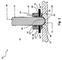
- the hollow cylindrical reactor sleeve 05 has a cylinder axis and a central through opening extending therefrom from a first end face 19 facing the starting material 03 to an opposite, second end face 20 of the reactor sleeve 05 facing away from the starting material 03.
- the tool 02 is movably guided in the central passage opening of the reactor sleeve 05 along a machining axis coinciding with the cylinder axis.
- the reactor sleeve 05 is preferably arranged upright on the starting material 03 and / or can be arranged.
- the invention may comprise a sealing arrangement formed by seals 17, 18 for an apparatus for electrochemical ablation.
- the hollow cylindrical reactor sleeve 05 can be designed as a straight or slated hollow cylinder with a cross section of the starting material 03 running normal to the machining axis in a mathematical sense similar to the cross section of the central axis.
- the central manufactorngsö réelle can over the height of the reactor sleeve 05 seen along the cylinder axis have a constant cross-section.
- the cross section can widen to the first end side, for example, jump.
- Such an enlargement increases the volume of the reactor space 07 formed between the reactor sleeve 05, the tool 02 and the starting material 03.
- An electrolyte 10 flows into the reactor chamber 07 at least during the electrochemical removal through the inlet opening 08 and out of the reactor chamber 07 through the outlet opening 09. As a result, there is a throughflow associated with a permanent flushing of the reactor chamber 07, whereby deposits of the electrochemical erosion affecting sludge can be avoided.
- the reactor space 07 may be part of a closed circuit in which an electrolyte circulates during the electrochemical removal.
- the electrolyte circulates thus preferably in a closed circuit, part of which is the reactor space with its inlet and outlet openings.
- the negative pressure can be produced, for example, by sucking off the electrolyte 10 from the reactor space 07.
- the electrolyte 10 preferably circulates in a closed circuit which comprises the reactor space 07 via a feed line 12 connected to the inlet opening 08 and via a discharge line 13 connected to the outlet opening 09.
- the closed circuit can be seen in a direction indicated by arrows in the direction of circulation 14 of the electrolyte 11 between 13 and Feed line 12 arranged filter space and / or a Sedimentationsraum for deposition during electrochemical ablation resulting sludge.
- the closed circuit may have a seen in the direction of circulation 14 of the electrolyte 11 between discharge line 13 and inlet 12 arranged gas separator for deposition in the electrochemical ablation of gases produced.
- the negative pressure prevailing in the reactor chamber 07 with respect to an environment 11 outside the reactor chamber 07 can be produced by removing a vapor phase separated in the gas separator from the gas separator.
- the negative pressure prevailing in the reactor chamber 07 can be generated by suction of the electrolyte 10 from the reactor chamber 07 via the outlet opening 09.
- the negative mold 04 of the workpiece to be produced forming surfaces of the tool 02 are electrically conductive.
- the remaining surfaces of the tool 02, which do not form the negative mold 04 of the workpiece to be produced, can be completely or partially coated in an electrically insulating manner, for example anodized.
- the electrically insulating coating may comprise, for example, a natural oxide and / or ceramic layer 15 of the material of the tool 02.
- At least the negative mold 04 formed on the side of the tool 02 facing the starting material 03 to be treated may be coated in an electrically conductive manner.
- the negative mold 04 formed on the side of the tool 02 facing the starting material 03 to be treated may, for example, be provided with an electrically conductive coating 16 of gold and / or silver and / or platinum and / or palladium and / or chromium.
- the tool 02 may be made of aluminum, titanium or coated steel.
- Aluminum and titanium are suitable both as a good electrically conductive material, as well as they form an electrically non-conductive and / or highly insulating surface of ceramic and / or anodized by oxidation.
- aluminum and titanium are suitable for coating with partially highly conductive surfaces, which behave as cathodically polarized electrodes for removal against steel passively and thus absorb no particles.
- the tool 02 may be embodied as an inert electrode made of mixed crystals.
- the starting material 03 may be or comprise, for example, steel and / or carbon steel and / or austenitic steel and / or a nickel-based alloy.
- Acid or alkali-containing solutions can also be used in the proposed invention.
- acids such as. As sulfuric acid, chromic acid, phosphoric acid u. a. as well as alkaline solutions such as caustic soda are used.
- Another advantage of the invention is that not only the removal rate can be increased, but also the quality of the product, as a better erosion z.
- B. aluminum and copper alloys is possible.
- the method and / or the device may comprise individual or a combination of features mentioned in the introduction of the prior art and / or features contained in prior art documents mentioned in the background.
- the invention is particularly industrially applicable in the field of production of metallic workpieces.
Landscapes
- Chemical & Material Sciences (AREA)
- Chemical Kinetics & Catalysis (AREA)
- Electrochemistry (AREA)
- Engineering & Computer Science (AREA)
- Mechanical Engineering (AREA)
- Physical Or Chemical Processes And Apparatus (AREA)
- ing And Chemical Polishing (AREA)
- Electrical Discharge Machining, Electrochemical Machining, And Combined Machining (AREA)
Priority Applications (1)
| Application Number | Priority Date | Filing Date | Title |
|---|---|---|---|
| PL16000951T PL3088115T3 (pl) | 2015-04-27 | 2016-04-27 | Sposób wytwarzania przedmiotu obrabianego |
Applications Claiming Priority (1)
| Application Number | Priority Date | Filing Date | Title |
|---|---|---|---|
| DE102015106432.4A DE102015106432A1 (de) | 2015-04-27 | 2015-04-27 | Verfahren und Vorrichtung zur Herstellung eines Werkstücks |
Publications (2)
| Publication Number | Publication Date |
|---|---|
| EP3088115A1 true EP3088115A1 (fr) | 2016-11-02 |
| EP3088115B1 EP3088115B1 (fr) | 2019-04-03 |
Family
ID=55860674
Family Applications (1)
| Application Number | Title | Priority Date | Filing Date |
|---|---|---|---|
| EP16000951.0A Active EP3088115B1 (fr) | 2015-04-27 | 2016-04-27 | Procede de fabrication d'une pieces usinee |
Country Status (7)
| Country | Link |
|---|---|
| EP (1) | EP3088115B1 (fr) |
| DE (1) | DE102015106432A1 (fr) |
| ES (1) | ES2732878T3 (fr) |
| HU (1) | HUE044780T2 (fr) |
| PL (1) | PL3088115T3 (fr) |
| PT (1) | PT3088115T (fr) |
| TR (1) | TR201909532T4 (fr) |
Cited By (2)
| Publication number | Priority date | Publication date | Assignee | Title |
|---|---|---|---|---|
| DE102018110905A1 (de) * | 2018-05-07 | 2019-11-07 | Lucas Automotive Gmbh | Elektrode für ein Eloxal-Verfahren |
| CN111936671A (zh) * | 2018-04-10 | 2020-11-13 | 西门子股份公司 | 用于选择性地电化学加工工件的装置和用于以这种装置制造工件的设备 |
Citations (13)
| Publication number | Priority date | Publication date | Assignee | Title |
|---|---|---|---|---|
| US3254013A (en) * | 1962-07-27 | 1966-05-31 | Anocut Eng Co | Electrolytic cavity sinking apparatus |
| DE1959852A1 (de) * | 1968-12-19 | 1970-06-25 | Cincinnati Milling Machine Co | Fluessigkeitszufuehrung fuer Elektroerosionsmaschinen |
| US3547798A (en) * | 1967-03-29 | 1970-12-15 | Cincinnati Milacron Inc | Electrochemical machining tool |
| DE2234424A1 (de) | 1972-07-13 | 1974-01-31 | Kalle Ag | Verfahren und vorrichtung zur kontinuierlichen elektrochemischen behandlung von metallbaendern |
| DE3030664A1 (de) | 1980-08-13 | 1982-03-18 | Siemens AG, 1000 Berlin und 8000 München | Verfahren zur bestimmung der stromausbeute bei galvanischen baedern |
| DE3125565A1 (de) | 1980-07-07 | 1982-04-01 | Hooker Chemicals & Plastics Corp., 48089 Warren, Mich. | "elektrochemisches entmetallisierungsbad und ein verfahren zum entmetallisieren" |
| WO2001038030A1 (fr) * | 1999-11-25 | 2001-05-31 | Frembgen Fritz Herbert | Procede d'usinage electrochimique de pieces |
| DE10028675A1 (de) | 1999-11-25 | 2001-05-31 | Frembgen Fritz Herbert | Verfahren zur Bearbeitung von Werkstücken |
| DE102006034277A1 (de) | 2006-07-21 | 2008-01-24 | Gramm Technik Gmbh | Vorrichtung zur Oberflächenbehandlung eines Werkstücks |
| DE102007049495A1 (de) | 2007-09-14 | 2009-03-19 | Extrude Hone Gmbh | Vorrichtung und Verfahren zur elektrochemischen Bearbeitung |
| CN101633066A (zh) * | 2009-07-24 | 2010-01-27 | 南京航空航天大学 | 真空反流电解加工方法及装置 |
| DE102011122523A1 (de) | 2011-12-29 | 2013-07-04 | Minebea Co., Ltd. | Elektrode für ein elektrochemisches Abtragverfahren |
| DE102012110016A1 (de) | 2012-10-19 | 2014-04-24 | Bernhard Wietrzynski | Verfahren und Vorrichtung zum Herstellen einer Vertiefung mit Hinterschneidung |
Family Cites Families (1)
| Publication number | Priority date | Publication date | Assignee | Title |
|---|---|---|---|---|
| HU194513B (en) * | 1985-08-02 | 1988-02-29 | Latszereszeti Eszkoezoek Gyara | System for the electrolytic treatment of shaped workpieces |
-
2015
- 2015-04-27 DE DE102015106432.4A patent/DE102015106432A1/de not_active Withdrawn
-
2016
- 2016-04-27 TR TR2019/09532T patent/TR201909532T4/tr unknown
- 2016-04-27 EP EP16000951.0A patent/EP3088115B1/fr active Active
- 2016-04-27 PT PT16000951T patent/PT3088115T/pt unknown
- 2016-04-27 HU HUE16000951 patent/HUE044780T2/hu unknown
- 2016-04-27 ES ES16000951T patent/ES2732878T3/es active Active
- 2016-04-27 PL PL16000951T patent/PL3088115T3/pl unknown
Patent Citations (13)
| Publication number | Priority date | Publication date | Assignee | Title |
|---|---|---|---|---|
| US3254013A (en) * | 1962-07-27 | 1966-05-31 | Anocut Eng Co | Electrolytic cavity sinking apparatus |
| US3547798A (en) * | 1967-03-29 | 1970-12-15 | Cincinnati Milacron Inc | Electrochemical machining tool |
| DE1959852A1 (de) * | 1968-12-19 | 1970-06-25 | Cincinnati Milling Machine Co | Fluessigkeitszufuehrung fuer Elektroerosionsmaschinen |
| DE2234424A1 (de) | 1972-07-13 | 1974-01-31 | Kalle Ag | Verfahren und vorrichtung zur kontinuierlichen elektrochemischen behandlung von metallbaendern |
| DE3125565A1 (de) | 1980-07-07 | 1982-04-01 | Hooker Chemicals & Plastics Corp., 48089 Warren, Mich. | "elektrochemisches entmetallisierungsbad und ein verfahren zum entmetallisieren" |
| DE3030664A1 (de) | 1980-08-13 | 1982-03-18 | Siemens AG, 1000 Berlin und 8000 München | Verfahren zur bestimmung der stromausbeute bei galvanischen baedern |
| WO2001038030A1 (fr) * | 1999-11-25 | 2001-05-31 | Frembgen Fritz Herbert | Procede d'usinage electrochimique de pieces |
| DE10028675A1 (de) | 1999-11-25 | 2001-05-31 | Frembgen Fritz Herbert | Verfahren zur Bearbeitung von Werkstücken |
| DE102006034277A1 (de) | 2006-07-21 | 2008-01-24 | Gramm Technik Gmbh | Vorrichtung zur Oberflächenbehandlung eines Werkstücks |
| DE102007049495A1 (de) | 2007-09-14 | 2009-03-19 | Extrude Hone Gmbh | Vorrichtung und Verfahren zur elektrochemischen Bearbeitung |
| CN101633066A (zh) * | 2009-07-24 | 2010-01-27 | 南京航空航天大学 | 真空反流电解加工方法及装置 |
| DE102011122523A1 (de) | 2011-12-29 | 2013-07-04 | Minebea Co., Ltd. | Elektrode für ein elektrochemisches Abtragverfahren |
| DE102012110016A1 (de) | 2012-10-19 | 2014-04-24 | Bernhard Wietrzynski | Verfahren und Vorrichtung zum Herstellen einer Vertiefung mit Hinterschneidung |
Non-Patent Citations (1)
| Title |
|---|
| DATABASE WPI Week 201014, Derwent World Patents Index; AN 2010-B49701, XP002761505 * |
Cited By (3)
| Publication number | Priority date | Publication date | Assignee | Title |
|---|---|---|---|---|
| CN111936671A (zh) * | 2018-04-10 | 2020-11-13 | 西门子股份公司 | 用于选择性地电化学加工工件的装置和用于以这种装置制造工件的设备 |
| DE102018110905A1 (de) * | 2018-05-07 | 2019-11-07 | Lucas Automotive Gmbh | Elektrode für ein Eloxal-Verfahren |
| WO2019214879A1 (fr) | 2018-05-07 | 2019-11-14 | Zf Active Safety Gmbh | Électrode pour procédé d'anodisation |
Also Published As
| Publication number | Publication date |
|---|---|
| EP3088115B1 (fr) | 2019-04-03 |
| ES2732878T3 (es) | 2019-11-26 |
| HUE044780T2 (hu) | 2019-11-28 |
| PT3088115T (pt) | 2019-07-12 |
| TR201909532T4 (tr) | 2019-07-22 |
| PL3088115T3 (pl) | 2019-09-30 |
| DE102015106432A1 (de) | 2016-10-27 |
Similar Documents
| Publication | Publication Date | Title |
|---|---|---|
| DE60011125T2 (de) | Verfahren und vorrichtung zur reinigung und/oder beschichtung von metalloberflächen mittels elektroplasma-technologie | |
| DE69403817T2 (de) | Verfahren zum elektrolytischen Polieren mit einer STEM-Elektrode | |
| DE3739580A1 (de) | Verfahren und vorrichtung zur spaltung eines dispersen systems in einer elektrochemischen zelle | |
| DE2834946A1 (de) | Elektrochemisches behandlungsverfahren | |
| EP3000918B1 (fr) | Procédé et dispositif d'application galvanique d'un revêtement de surface | |
| DE102012201305B4 (de) | Elektrode und Anlage zum elektrochemischen Bearbeiten sowie Verfahren hierzu | |
| EP3088115B1 (fr) | Procede de fabrication d'une pieces usinee | |
| DE69400559T2 (de) | Verfahren und Vorrichtung zum elektrochemischen Ätzen von metallischen Werkstoffen und zwar insbesondere der Innenseite der Böden von Kernreaktorbehältern | |
| DE1298388B (de) | Verfahren und Vorrichtung zur elektrolytischen Bearbeitung eines metallenen Werkstoffes | |
| WO2019214879A1 (fr) | Électrode pour procédé d'anodisation | |
| EP3468739A1 (fr) | Procédé et dispositif permettant de produire des rayures dans le canon d'armes à feu | |
| DE3785278T2 (de) | Zelle zur kontinuierlichen elektrolytischen Abscheidungsbehandlung von Stangen und ähnlichem. | |
| EP4136276A1 (fr) | Cellule électrolytique, procédé de fonctionnement d'une cellule dudit type et électrolyseur | |
| EP2190617B1 (fr) | Procédé d'usinage électro-chimique | |
| DE102018200308B4 (de) | Verfahren zur herstellung einer werkzeugelektrode und verfahren zu ihrer verwendung | |
| DE10249194B4 (de) | Verfahren und Vorrichtung zur Durchführung einer anodischen Behandlung | |
| EP1902161B1 (fr) | Ensemble d'electrodes et procede de revetement electrochimique de la surface d'une piece | |
| DE102019003597A1 (de) | Verfahren und Anlage zum Plasmapolieren | |
| EP1533398B1 (fr) | Procédé pour la production d'un électrolyte prêt à utilisation à partir de déchets contenant des ions métalliques | |
| AT340735B (de) | Vorrichtung zum elektroplattieren | |
| WO2017076456A1 (fr) | Procédé et dispositif d'application d'un revêtement de surface par galvanisation | |
| DE102011084051B4 (de) | Beschichteter Kolbenring mit radial zunehmender Schichtdicke und Verfahren zu dessen Herstellung | |
| DE102015212330A1 (de) | Verfahren zum Beschichten eines Laufrades, insbesondere eines Turbinenrads und/oder Verdichterrads, eines Abgasturboladers | |
| EP4570965A1 (fr) | Dispositif et procédé de dépôt galvanique de chrome | |
| DE102022003365A1 (de) | Vorrichtung und Verfahren zum elektrolytischen Polieren |
Legal Events
| Date | Code | Title | Description |
|---|---|---|---|
| PUAI | Public reference made under article 153(3) epc to a published international application that has entered the european phase |
Free format text: ORIGINAL CODE: 0009012 |
|
| AK | Designated contracting states |
Kind code of ref document: A1 Designated state(s): AL AT BE BG CH CY CZ DE DK EE ES FI FR GB GR HR HU IE IS IT LI LT LU LV MC MK MT NL NO PL PT RO RS SE SI SK SM TR |
|
| AX | Request for extension of the european patent |
Extension state: BA ME |
|
| 17P | Request for examination filed |
Effective date: 20170502 |
|
| RBV | Designated contracting states (corrected) |
Designated state(s): AL AT BE BG CH CY CZ DE DK EE ES FI FR GB GR HR HU IE IS IT LI LT LU LV MC MK MT NL NO PL PT RO RS SE SI SK SM TR |
|
| STAA | Information on the status of an ep patent application or granted ep patent |
Free format text: STATUS: REQUEST FOR EXAMINATION WAS MADE |
|
| GRAP | Despatch of communication of intention to grant a patent |
Free format text: ORIGINAL CODE: EPIDOSNIGR1 |
|
| STAA | Information on the status of an ep patent application or granted ep patent |
Free format text: STATUS: GRANT OF PATENT IS INTENDED |
|
| RIC1 | Information provided on ipc code assigned before grant |
Ipc: B23H 9/14 20060101ALN20181011BHEP Ipc: B23H 3/10 20060101AFI20181011BHEP |
|
| INTG | Intention to grant announced |
Effective date: 20181031 |
|
| GRAS | Grant fee paid |
Free format text: ORIGINAL CODE: EPIDOSNIGR3 |
|
| GRAA | (expected) grant |
Free format text: ORIGINAL CODE: 0009210 |
|
| STAA | Information on the status of an ep patent application or granted ep patent |
Free format text: STATUS: THE PATENT HAS BEEN GRANTED |
|
| AK | Designated contracting states |
Kind code of ref document: B1 Designated state(s): AL AT BE BG CH CY CZ DE DK EE ES FI FR GB GR HR HU IE IS IT LI LT LU LV MC MK MT NL NO PL PT RO RS SE SI SK SM TR |
|
| REG | Reference to a national code |
Ref country code: GB Ref legal event code: FG4D Free format text: NOT ENGLISH |
|
| REG | Reference to a national code |
Ref country code: CH Ref legal event code: EP Ref country code: AT Ref legal event code: REF Ref document number: 1115121 Country of ref document: AT Kind code of ref document: T Effective date: 20190415 |
|
| REG | Reference to a national code |
Ref country code: DE Ref legal event code: R096 Ref document number: 502016003941 Country of ref document: DE |
|
| REG | Reference to a national code |
Ref country code: IE Ref legal event code: FG4D Free format text: LANGUAGE OF EP DOCUMENT: GERMAN |
|
| REG | Reference to a national code |
Ref country code: PT Ref legal event code: SC4A Ref document number: 3088115 Country of ref document: PT Date of ref document: 20190712 Kind code of ref document: T Free format text: AVAILABILITY OF NATIONAL TRANSLATION Effective date: 20190702 |
|
| REG | Reference to a national code |
Ref country code: NL Ref legal event code: FP |
|
| REG | Reference to a national code |
Ref country code: SE Ref legal event code: TRGR |
|
| PGFP | Annual fee paid to national office [announced via postgrant information from national office to epo] |
Ref country code: IT Payment date: 20190430 Year of fee payment: 4 |
|
| REG | Reference to a national code |
Ref country code: LT Ref legal event code: MG4D |
|
| PGFP | Annual fee paid to national office [announced via postgrant information from national office to epo] |
Ref country code: NL Payment date: 20190628 Year of fee payment: 4 Ref country code: FR Payment date: 20190628 Year of fee payment: 4 |
|
| PG25 | Lapsed in a contracting state [announced via postgrant information from national office to epo] |
Ref country code: HR Free format text: LAPSE BECAUSE OF FAILURE TO SUBMIT A TRANSLATION OF THE DESCRIPTION OR TO PAY THE FEE WITHIN THE PRESCRIBED TIME-LIMIT Effective date: 20190403 Ref country code: LT Free format text: LAPSE BECAUSE OF FAILURE TO SUBMIT A TRANSLATION OF THE DESCRIPTION OR TO PAY THE FEE WITHIN THE PRESCRIBED TIME-LIMIT Effective date: 20190403 Ref country code: NO Free format text: LAPSE BECAUSE OF FAILURE TO SUBMIT A TRANSLATION OF THE DESCRIPTION OR TO PAY THE FEE WITHIN THE PRESCRIBED TIME-LIMIT Effective date: 20190703 Ref country code: FI Free format text: LAPSE BECAUSE OF FAILURE TO SUBMIT A TRANSLATION OF THE DESCRIPTION OR TO PAY THE FEE WITHIN THE PRESCRIBED TIME-LIMIT Effective date: 20190403 Ref country code: AL Free format text: LAPSE BECAUSE OF FAILURE TO SUBMIT A TRANSLATION OF THE DESCRIPTION OR TO PAY THE FEE WITHIN THE PRESCRIBED TIME-LIMIT Effective date: 20190403 |
|
| PGFP | Annual fee paid to national office [announced via postgrant information from national office to epo] |
Ref country code: GB Payment date: 20190627 Year of fee payment: 5 Ref country code: CZ Payment date: 20190711 Year of fee payment: 4 Ref country code: ES Payment date: 20190722 Year of fee payment: 4 Ref country code: SE Payment date: 20190628 Year of fee payment: 4 |
|
| REG | Reference to a national code |
Ref country code: ES Ref legal event code: FG2A Ref document number: 2732878 Country of ref document: ES Kind code of ref document: T3 Effective date: 20191126 |
|
| REG | Reference to a national code |
Ref country code: HU Ref legal event code: AG4A Ref document number: E044780 Country of ref document: HU |
|
| PG25 | Lapsed in a contracting state [announced via postgrant information from national office to epo] |
Ref country code: GR Free format text: LAPSE BECAUSE OF FAILURE TO SUBMIT A TRANSLATION OF THE DESCRIPTION OR TO PAY THE FEE WITHIN THE PRESCRIBED TIME-LIMIT Effective date: 20190704 Ref country code: BG Free format text: LAPSE BECAUSE OF FAILURE TO SUBMIT A TRANSLATION OF THE DESCRIPTION OR TO PAY THE FEE WITHIN THE PRESCRIBED TIME-LIMIT Effective date: 20190703 Ref country code: RS Free format text: LAPSE BECAUSE OF FAILURE TO SUBMIT A TRANSLATION OF THE DESCRIPTION OR TO PAY THE FEE WITHIN THE PRESCRIBED TIME-LIMIT Effective date: 20190403 Ref country code: LV Free format text: LAPSE BECAUSE OF FAILURE TO SUBMIT A TRANSLATION OF THE DESCRIPTION OR TO PAY THE FEE WITHIN THE PRESCRIBED TIME-LIMIT Effective date: 20190403 |
|
| PGFP | Annual fee paid to national office [announced via postgrant information from national office to epo] |
Ref country code: HU Payment date: 20190724 Year of fee payment: 4 Ref country code: BE Payment date: 20190628 Year of fee payment: 4 Ref country code: PL Payment date: 20190710 Year of fee payment: 4 |
|
| REG | Reference to a national code |
Ref country code: CH Ref legal event code: PL |
|
| PG25 | Lapsed in a contracting state [announced via postgrant information from national office to epo] |
Ref country code: LU Free format text: LAPSE BECAUSE OF NON-PAYMENT OF DUE FEES Effective date: 20190427 Ref country code: IS Free format text: LAPSE BECAUSE OF FAILURE TO SUBMIT A TRANSLATION OF THE DESCRIPTION OR TO PAY THE FEE WITHIN THE PRESCRIBED TIME-LIMIT Effective date: 20190803 |
|
| REG | Reference to a national code |
Ref country code: DE Ref legal event code: R097 Ref document number: 502016003941 Country of ref document: DE |
|
| PG25 | Lapsed in a contracting state [announced via postgrant information from national office to epo] |
Ref country code: DK Free format text: LAPSE BECAUSE OF FAILURE TO SUBMIT A TRANSLATION OF THE DESCRIPTION OR TO PAY THE FEE WITHIN THE PRESCRIBED TIME-LIMIT Effective date: 20190403 Ref country code: MC Free format text: LAPSE BECAUSE OF FAILURE TO SUBMIT A TRANSLATION OF THE DESCRIPTION OR TO PAY THE FEE WITHIN THE PRESCRIBED TIME-LIMIT Effective date: 20190403 Ref country code: SK Free format text: LAPSE BECAUSE OF FAILURE TO SUBMIT A TRANSLATION OF THE DESCRIPTION OR TO PAY THE FEE WITHIN THE PRESCRIBED TIME-LIMIT Effective date: 20190403 Ref country code: LI Free format text: LAPSE BECAUSE OF NON-PAYMENT OF DUE FEES Effective date: 20190430 Ref country code: RO Free format text: LAPSE BECAUSE OF FAILURE TO SUBMIT A TRANSLATION OF THE DESCRIPTION OR TO PAY THE FEE WITHIN THE PRESCRIBED TIME-LIMIT Effective date: 20190403 Ref country code: CH Free format text: LAPSE BECAUSE OF NON-PAYMENT OF DUE FEES Effective date: 20190430 Ref country code: EE Free format text: LAPSE BECAUSE OF FAILURE TO SUBMIT A TRANSLATION OF THE DESCRIPTION OR TO PAY THE FEE WITHIN THE PRESCRIBED TIME-LIMIT Effective date: 20190403 |
|
| PLBE | No opposition filed within time limit |
Free format text: ORIGINAL CODE: 0009261 |
|
| STAA | Information on the status of an ep patent application or granted ep patent |
Free format text: STATUS: NO OPPOSITION FILED WITHIN TIME LIMIT |
|
| PG25 | Lapsed in a contracting state [announced via postgrant information from national office to epo] |
Ref country code: SM Free format text: LAPSE BECAUSE OF FAILURE TO SUBMIT A TRANSLATION OF THE DESCRIPTION OR TO PAY THE FEE WITHIN THE PRESCRIBED TIME-LIMIT Effective date: 20190403 |
|
| 26N | No opposition filed |
Effective date: 20200106 |
|
| PG25 | Lapsed in a contracting state [announced via postgrant information from national office to epo] |
Ref country code: IE Free format text: LAPSE BECAUSE OF NON-PAYMENT OF DUE FEES Effective date: 20190427 |
|
| PG25 | Lapsed in a contracting state [announced via postgrant information from national office to epo] |
Ref country code: SI Free format text: LAPSE BECAUSE OF FAILURE TO SUBMIT A TRANSLATION OF THE DESCRIPTION OR TO PAY THE FEE WITHIN THE PRESCRIBED TIME-LIMIT Effective date: 20190403 |
|
| REG | Reference to a national code |
Ref country code: NL Ref legal event code: MM Effective date: 20200501 |
|
| PG25 | Lapsed in a contracting state [announced via postgrant information from national office to epo] |
Ref country code: FR Free format text: LAPSE BECAUSE OF NON-PAYMENT OF DUE FEES Effective date: 20200430 Ref country code: HU Free format text: LAPSE BECAUSE OF NON-PAYMENT OF DUE FEES Effective date: 20200428 Ref country code: SE Free format text: LAPSE BECAUSE OF NON-PAYMENT OF DUE FEES Effective date: 20200428 Ref country code: CZ Free format text: LAPSE BECAUSE OF NON-PAYMENT OF DUE FEES Effective date: 20200427 |
|
| REG | Reference to a national code |
Ref country code: BE Ref legal event code: MM Effective date: 20200430 |
|
| PG25 | Lapsed in a contracting state [announced via postgrant information from national office to epo] |
Ref country code: BE Free format text: LAPSE BECAUSE OF NON-PAYMENT OF DUE FEES Effective date: 20200430 |
|
| GBPC | Gb: european patent ceased through non-payment of renewal fee |
Effective date: 20200427 |
|
| PG25 | Lapsed in a contracting state [announced via postgrant information from national office to epo] |
Ref country code: NL Free format text: LAPSE BECAUSE OF NON-PAYMENT OF DUE FEES Effective date: 20200501 |
|
| PG25 | Lapsed in a contracting state [announced via postgrant information from national office to epo] |
Ref country code: GB Free format text: LAPSE BECAUSE OF NON-PAYMENT OF DUE FEES Effective date: 20200427 Ref country code: PT Free format text: LAPSE BECAUSE OF NON-PAYMENT OF DUE FEES Effective date: 20210127 |
|
| PG25 | Lapsed in a contracting state [announced via postgrant information from national office to epo] |
Ref country code: CY Free format text: LAPSE BECAUSE OF FAILURE TO SUBMIT A TRANSLATION OF THE DESCRIPTION OR TO PAY THE FEE WITHIN THE PRESCRIBED TIME-LIMIT Effective date: 20190403 |
|
| PG25 | Lapsed in a contracting state [announced via postgrant information from national office to epo] |
Ref country code: MT Free format text: LAPSE BECAUSE OF FAILURE TO SUBMIT A TRANSLATION OF THE DESCRIPTION OR TO PAY THE FEE WITHIN THE PRESCRIBED TIME-LIMIT Effective date: 20190403 |
|
| REG | Reference to a national code |
Ref country code: ES Ref legal event code: FD2A Effective date: 20210831 |
|
| PG25 | Lapsed in a contracting state [announced via postgrant information from national office to epo] |
Ref country code: IT Free format text: LAPSE BECAUSE OF NON-PAYMENT OF DUE FEES Effective date: 20200427 |
|
| PG25 | Lapsed in a contracting state [announced via postgrant information from national office to epo] |
Ref country code: ES Free format text: LAPSE BECAUSE OF NON-PAYMENT OF DUE FEES Effective date: 20200428 |
|
| PG25 | Lapsed in a contracting state [announced via postgrant information from national office to epo] |
Ref country code: TR Free format text: LAPSE BECAUSE OF NON-PAYMENT OF DUE FEES Effective date: 20200427 Ref country code: MK Free format text: LAPSE BECAUSE OF FAILURE TO SUBMIT A TRANSLATION OF THE DESCRIPTION OR TO PAY THE FEE WITHIN THE PRESCRIBED TIME-LIMIT Effective date: 20190403 |
|
| PG25 | Lapsed in a contracting state [announced via postgrant information from national office to epo] |
Ref country code: PL Free format text: LAPSE BECAUSE OF NON-PAYMENT OF DUE FEES Effective date: 20200427 |
|
| PGFP | Annual fee paid to national office [announced via postgrant information from national office to epo] |
Ref country code: DE Payment date: 20250422 Year of fee payment: 10 |
|
| PGFP | Annual fee paid to national office [announced via postgrant information from national office to epo] |
Ref country code: AT Payment date: 20250423 Year of fee payment: 10 |