EP3088128B1 - Système d'alimentation en composants - Google Patents
Système d'alimentation en composants Download PDFInfo
- Publication number
- EP3088128B1 EP3088128B1 EP13900204.2A EP13900204A EP3088128B1 EP 3088128 B1 EP3088128 B1 EP 3088128B1 EP 13900204 A EP13900204 A EP 13900204A EP 3088128 B1 EP3088128 B1 EP 3088128B1
- Authority
- EP
- European Patent Office
- Prior art keywords
- component
- support surface
- section
- holding
- imaging
- Prior art date
- Legal status (The legal status is an assumption and is not a legal conclusion. Google has not performed a legal analysis and makes no representation as to the accuracy of the status listed.)
- Active
Links
Images






Classifications
-
- H—ELECTRICITY
- H05—ELECTRIC TECHNIQUES NOT OTHERWISE PROVIDED FOR
- H05K—PRINTED CIRCUITS; CASINGS OR CONSTRUCTIONAL DETAILS OF ELECTRIC APPARATUS; MANUFACTURE OF ASSEMBLAGES OF ELECTRICAL COMPONENTS
- H05K13/00—Apparatus or processes specially adapted for manufacturing or adjusting assemblages of electric components
- H05K13/02—Feeding of components
- H05K13/021—Loading or unloading of containers
-
- B—PERFORMING OPERATIONS; TRANSPORTING
- B23—MACHINE TOOLS; METAL-WORKING NOT OTHERWISE PROVIDED FOR
- B23P—METAL-WORKING NOT OTHERWISE PROVIDED FOR; COMBINED OPERATIONS; UNIVERSAL MACHINE TOOLS
- B23P19/00—Machines for simply fitting together or separating metal parts or objects, or metal and non-metal parts, whether or not involving some deformation; Tools or devices therefor so far as not provided for in other classes
- B23P19/001—Article feeders for assembling machines
-
- B—PERFORMING OPERATIONS; TRANSPORTING
- B65—CONVEYING; PACKING; STORING; HANDLING THIN OR FILAMENTARY MATERIAL
- B65G—TRANSPORT OR STORAGE DEVICES, e.g. CONVEYORS FOR LOADING OR TIPPING, SHOP CONVEYOR SYSTEMS OR PNEUMATIC TUBE CONVEYORS
- B65G47/00—Article or material-handling devices associated with conveyors; Methods employing such devices
- B65G47/02—Devices for feeding articles or materials to conveyors
- B65G47/04—Devices for feeding articles or materials to conveyors for feeding articles
- B65G47/12—Devices for feeding articles or materials to conveyors for feeding articles from disorderly-arranged article piles or from loose assemblages of articles
- B65G47/14—Devices for feeding articles or materials to conveyors for feeding articles from disorderly-arranged article piles or from loose assemblages of articles arranging or orientating the articles by mechanical or pneumatic means during feeding
- B65G47/1407—Devices for feeding articles or materials to conveyors for feeding articles from disorderly-arranged article piles or from loose assemblages of articles arranging or orientating the articles by mechanical or pneumatic means during feeding the articles being fed from a container, e.g. a bowl
- B65G47/1442—Devices for feeding articles or materials to conveyors for feeding articles from disorderly-arranged article piles or from loose assemblages of articles arranging or orientating the articles by mechanical or pneumatic means during feeding the articles being fed from a container, e.g. a bowl by means of movement of the bottom or a part of the wall of the container
- B65G47/145—Jigging or reciprocating movement
-
- H—ELECTRICITY
- H05—ELECTRIC TECHNIQUES NOT OTHERWISE PROVIDED FOR
- H05K—PRINTED CIRCUITS; CASINGS OR CONSTRUCTIONAL DETAILS OF ELECTRIC APPARATUS; MANUFACTURE OF ASSEMBLAGES OF ELECTRICAL COMPONENTS
- H05K13/00—Apparatus or processes specially adapted for manufacturing or adjusting assemblages of electric components
- H05K13/02—Feeding of components
- H05K13/028—Simultaneously loading a plurality of loose objects, e.g. by means of vibrations, pressure differences, magnetic fields
-
- H—ELECTRICITY
- H05—ELECTRIC TECHNIQUES NOT OTHERWISE PROVIDED FOR
- H05K—PRINTED CIRCUITS; CASINGS OR CONSTRUCTIONAL DETAILS OF ELECTRIC APPARATUS; MANUFACTURE OF ASSEMBLAGES OF ELECTRICAL COMPONENTS
- H05K13/00—Apparatus or processes specially adapted for manufacturing or adjusting assemblages of electric components
- H05K13/08—Monitoring manufacture of assemblages
- H05K13/081—Integration of optical monitoring devices in assembly lines; Processes using optical monitoring devices specially adapted for controlling devices or machines in assembly lines
- H05K13/0813—Controlling of single components prior to mounting, e.g. orientation, component geometry
Definitions
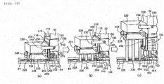
- the component support member 150 is fixed to the slide 164 in a pair of leg sections 158, and moves a position slightly below the lower end of the scraping-out member 114 by the slide 164 moving in the front and back direction by guiding to a pair of guide rails 168 using the slide driving device 166.
- the component support member 150 is moved in the horizontal direction which is a parallel direction to the upper surface 160, as shown in Fig. 4 , is moved to a component supply position at which the entirety of the upper surface 160 is positioned in front of the component feeder 82, and as shown in Fig. 6 , to a retraction position at which the front section is positioned below the component feeder 82 and at which the front end of the upper surface 160 is positioned on the front end of the component feeder 82.
- the large number of teeth 190 are respectively defined by an inclined surface 192 which is inclined in an orientation upward toward the rear and a vertical surface 194 which extends out downward in the vertical direction from the upper end of the inclined surface 192, and are configured by the cam surface 196 with a large number of concavities and convexities lined up along a straight line parallel to the front and back direction using the inclined surface 192 and the vertical surface 194.
- the cam member 180 is provided in a section in the front and back direction of the component support member 150, and out of the upper surface 160, aportion which corresponds to the cam member 180 functions as a component support surface 198 in the front and back direction.
- the motion conversion mechanism 224 includes a pair of rollers 240 which configure an engaged section by providing in the component collecting container 220 and a pair of engagement surfaces 242 which configure an engaging section by being provided in the frame 94.
- One roller 240 and an engagement surface 242 are illustrated in Figs. 8 and 11 .
- the roller 240 is attached to be able to rotate about an axis line parallel to the lateral direction in a projecting end section of a support member 244 that is fixed to protrude out to the rear from the component collecting container 220 which is positioned at the component reception position.
- the engagement surface 242 is provided in a portion which corresponds to the upper end section of the component accommodation section 100 of the frame 94, and is a horizontal plane with a downward orientation.
- the component support surface 198 is slightly smaller than the field of view of the imaging device 90 in the front and back direction, and the lateral direction is the size of the entirety of the upper surface 160.
- the length of the cam member 180 is set in combination with the height in the front and back direction of the component support surface 198.
- the imaging device 90 is disposed in a downward orientation above the component support surface 198 of the component support member 150 which is positioned at the component supply position, and is disposed at a posture which faces the component support surface 198.
- the imaging device 90 is moved by the imaging device moving device 270, selectively faces each of the component support surfaces 198 of the component supply unit 96 of five sets, and images a plurality of components on each component support surface 198 at each of the five imaging positions.
- the shuttle devices 304 and 306 respectively include component carriers 450 and 452 and component carrier moving devices 454 and 456, and are provided to line up in the lateral direction further to the front side than the component supply unit 96 of the system main body 80.
- each of the component carriers 450 and 452 detachably holds a component receiving member 460 to configure a component receiving section.
- the component receiving member 460 is engaged in a recessed section 462 of the component carriers 450 and 452, and is held by respectively positionally aligning in the front and back direction and the lateral direction using protruding sections 464 and 466.
- the component carriers 450 and 452 are respectively able to hold at least one component receiving member 460, a plurality in the present embodiment, for example, five in a state of being lined up in a row in the lateral direction.
- the component carriers 450 and 452 are moved independently from each other between a component receiving position which is positioned in a front section of a movement region of the component holding head 300, close to the component holding head moving device 302, and adjacent to the component supply unit 96, and a component delivery position which is positioned in a rear section of the movement region of the mounting head 50, and close to the component mounting device 20.
- the component carriers 450 and 452 are positionally aligned with the component receiving position and the component delivery position using a stopper (not illustrated) which is provided on the moving device main body 520.
- the component holding head 300 is positioned at the retraction position, and imaging of the component is permitted by the imaging device 90. After imaging, the component holding head 300 is moved to the function position, and after imaging by the imaging device 90, the holding target component is held on the component support surface 198 which maintains a stationary state of stopping without change.
- the components are held one by one according to an order set in advance.
- the order is an order of holding from the component which is positioned on the frontmost side in the front and back direction, and positioned furthest on the downstream side in the board conveyance direction in the lateral direction.
- the component holding head 300 reciprocally moves between the component carriers 450 and 452 and the component support surface 198, the component is selectively picked up from five component supply units 96 and is held in the component carrier 450 or the component carrier 452.
- the component carrier is moved to the component delivery position.
- the mounting head 50 of the component mounting device 20 is moved to the component carrier which is positioned at the component delivery position, and the component on the component receiving member 460 is sucked by the suction nozzle 70 and picked up.
- the component 480 is accommodated in the component receiving member 460 in a state in which the lead 484 is oriented downward and the suctionable side surfaces 486 are upper surfaces, and it is possible for the suction nozzle 70 to reliably suck the component 480.
- the mounting head 50 is moved to the imaging device 24, and the component 480 which is held in the suction nozzle 70 is imaged. Based on the imaging data obtained as a result of imaging, a phase difference between a rotation phase about the vertical line of the component 480 and a mounting phase of the circuit board 12, and a holding position error of the component 480 using the suction nozzle 70 are calculated, and both are corrected and the component 480 is mounted on the board 12.
- the lead 484 is inserted in a lead insertion hole of the board 12, and the component 480 is attached on the board 12.
- the entirety of the upper surface of the component support member may be the component support surface.
- the imaging device moving device moves the imaging device in the lateral direction and the front and back direction.
Landscapes
- Engineering & Computer Science (AREA)
- Manufacturing & Machinery (AREA)
- Microelectronics & Electronic Packaging (AREA)
- Mechanical Engineering (AREA)
- Operations Research (AREA)
- Supply And Installment Of Electrical Components (AREA)
- Automatic Assembly (AREA)
Claims (9)
- Système d'alimentation en composants (18) qui est configuré pour fournir des composants (480) en vrac à une section de réception de composants (20) d'un appareil d'assemblage automatisé dans une posture prédéterminée, le système (18) comprenant:un chargeur de composants (82) qui est configuré pour loger une pluralité de composants (480) en vrac dans une posture aléatoire et qui est configuré pour alimenter les composants logés (480);un dispositif de dispersion de composants (84) configuré pour disperser une pluralité de composants (480) à l'intérieur du chargeur de composants (82) sur une surface plate de support de composants (198) d'un élément de support de composants (150);un dispositif de distribution de composants (86) qui est configuré pour saisir les composants (150) sur la surface de support de composants (198) à l'aide d'un outil de maintien de composants (362) et qui est configuré pour délivrer les composants (480) à la section de réception de composants (20);un dispositif d'imagerie (90) qui est configuré pour imager une pluralité de composants (480) qui sont dispersés sur la surface de support de composants (198); etun dispositif de commande (550) qui est configuré pour commander le système d'alimentation en composants (18),dans lequel le dispositif de commande (550) comprend une section de commande d'imagerie et de maintien configurée pour amener le dispositif d'imagerie (90) à effectuer l'imagerie et configurée pour amener l'outil de maintien de composants (362) à maintenir les composants (480) pour que la surface de support de composants (198) soit maintenue dans un état stationnaire, de telle sorte que l'outil de maintien de composants (362) maintienne un composant (480) comme il convient pour être maintenu par l'outil de maintien de composants (362) en tant que composant cible de maintien parmi une pluralité de composants (480) qui sont dispersés sur la surface de support de composants (198) sur la base du résultat de la formation d'image par le dispositif d'imagerie (90)dans lequel le dispositif de distribution de composants (86) comprend:un dispositif de rotation d'outil de maintien (364) qui est capable de faire tourner l'outil de maintien de composants (362) selon un angle arbitraire autour d'une ligne d'axe de rotation orthogonale à la surface de support de composants (198), etun dispositif de pivotement d'outil de maintien (366) capable de faire pivoter l'outil de maintien de composants (362) autour d'une ligne d'axe de pivotement orthogonale à la ligne d'axe de rotation, etle dispositif de distribution de composants (86) est configuré pour tourner autour de la ligne d'axe de rotation et est configuré pour faire pivoter, autour de la ligne d'axe de pivotement, un composant (480) qui est saisi de la surface de support de composants (198) par l'outil de maintien de composants (362),caractérisé en ce quele système d'alimentation en composants (18) comprend une pluralité de chargeurs de composants (82) et une pluralité de surfaces de support de composants (198),dans lequel une pluralité des chargeurs de composants (82) et une pluralité de surfaces de support de composants (198) sont respectivement disposées pour s'aligner dans une direction latérale orthogonale à une direction avant et arrière qui est une direction de séparation des chargeurs de composants (82) et la section de réception de composants (20), etle système d'alimentation en composants (18) comprend en outre un dispositif de déplacement de dispositif d'imagerie (270) qui est configuré pour déplacer le dispositif d'imagerie (90) dans la direction latérale de sorte que le dispositif d'imagerie (90) fasse face de manière sélective à chacune d'une pluralité de surfaces de support de composants (198).
- Dispositif d'alimentation en composants (18) selon la revendication 1,
dans lequel le dispositif d'imagerie (90) est disposé au-dessus de la surface de support de composants (198) dans une position à laquelle le dispositif d'imagerie (90) fait face à la surface de support de composants (198), et le dispositif de distribution de composants (86) comprend un dispositif de déplacement d'outil de maintien (302) configuré pour déplacer l'outil de maintien de composants (362) dans une position fonctionnelle à laquelle l'outil de maintien de composants (362) est capable de maintenir le composant (480) sur la surface de support de composants (198) et une position de rétraction sur lequel l'outil de maintien de composants (362) est retiré de la position fonctionnelle, dans une plage située entre le dispositif de formation d'image (90) et la surface de support de composants (198) dans le sens de la hauteur. - Dispositif d'alimentation en composants (18) selon les revendications 1 ou 2,
dans lequel le dispositif de déplacement de dispositif d'imagerie (270) ne déplace pas le dispositif d'imagerie (90) dans les sens avant et arrière, et
le dispositif d'imagerie (90) est configuré pour imager une pluralité des composants (480) sur la surface de support de composants (198) dans chacune d'une pluralité de positions d'imagerie auxquelles le dispositif d'imagerie (90) fait face à chacune d'une pluralité de surfaces de support de composants (198). - Système d'alimentation en composants (18) selon l'une quelconque des revendications 1 à 3, dans lequel le dispositif de dispersion de composants (84) comprend l'élément de support de composants (150) qui est pourvu de la surface de support de composants (198),
un dispositif de déplacement relatif (152) qui est configuré pour déplacer de manière relative l'élément de support de composants (150) et le chargeur de composants (82) dans une direction parallèle à la surface de support de composants (198) de sorte que différentes parties de la surface de support de composants (198) correspondent de manière séquentielle à une section de décharge de composants (112) du chargeur de composants (82), et
un dispositif de vibration d'alimentation (154) qui est configuré pour faire vibrer le chargeur de composants (82) pendant le mouvement relatif de l'élément de support de composants (150) et du chargeur de composants (82) par le dispositif de déplacement relatif (152) pour décharger les composants (480) de la section de décharge de composants (112) sur la surface de support de composants (198). - Dispositif d'alimentation en composants (18) selon les revendications 1 à 4,
dans lequel le composant (480) qui est logé dans le chargeur de composants (82) est un composant (480) pourvu d'une section saillante (484) qui fait saillie depuis une surface et doit être inséré dans une section concave d'un élément cible d'assemblage, et la section de commande d'imagerie et de maintien est configurée pour déterminer un composant (480) sur la surface de support de composants (198) qui est isolé des autres composants (480), la section saillante (484) s'étendant dans une direction parallèle à la surface de support de composants (198) en tant que composant cible de maintien. - Dispositif d'alimentation en composants (18) selon les revendications 1 à 5, dans lequel le dispositif de distribution de composants (86) comprend:un dispositif de déplacement d'outil de maintien (302) qui est configuré pour déplacer l'outil de maintien de composant (362) dans une première direction et une deuxième direction orthogonales l'une à l'autre et parallèles à la surface de support de composants (198) et dans une troisième direction qui est orthogonale à la surface de support de composants (198), etun magasin de composants (450, 452) qui est configuré pour se déplacer entre une position de réception de composants proche du dispositif de déplacement d'outil de maintien (302) et une position de distribution de composants proche de la section de réception de composants (20) dans une direction sensiblement parallèle à la surface de support de composants (198), etdans un état dans lequel le magasin de composants (450, 452) est positionné à la position de réception de composants, le dispositif de déplacement d'outil de maintien (302) est configuré pour amener l'outil de maintien de composants (362) à faire en sorte que le magasin de composants (450, 452) reçoive un composant (480) et le magasin de composants (450, 452) est configuré pour transporter le composant reçu (480) vers la position de distribution de composants.
- Dispositif d'alimentation en composants (18) selon la revendication 6,
dans lequel une pluralité de supports de composants (450, 452) sont fournis, et une pluralité de magasins (450, 452) sont mobiles indépendamment les uns des autres entre la position de réception de composants et la position de distribution de composants. - Dispositif d'alimentation en composants (18) selon les revendications 6 ou 7,
dans lequel une section de réception de composants (460) du magasin de composants (450, 452) comprend une section en creux de réception de composants (500) conçue pour recevoir un composant (480), munie d'une section saillante (484) faisant saillie à partir d'une surface et devant être introduite dans une section concave d'un élément cible d'assemblage, la section saillante (484) étant orientée vers le bas. - Dispositif d'alimentation en composants (18) selon l'une quelconque des revendications 1 à 8, comprenant en outre:
un dispositif de retour de composants (88) qui est configuré pour retourner au chargeur de composants (82) un composant (480), qui reste sur la surface de support de composants (198), non déterminé comme composant cible de maintien par la section de commande d'imagerie et de maintien des composants (480) qui sont pris en charge sur la surface de support de composants (198).
Applications Claiming Priority (1)
| Application Number | Priority Date | Filing Date | Title |
|---|---|---|---|
| PCT/JP2013/085252 WO2015097904A1 (fr) | 2013-12-27 | 2013-12-27 | Système d'alimentation en composants |
Publications (3)
| Publication Number | Publication Date |
|---|---|
| EP3088128A1 EP3088128A1 (fr) | 2016-11-02 |
| EP3088128A4 EP3088128A4 (fr) | 2016-12-28 |
| EP3088128B1 true EP3088128B1 (fr) | 2019-08-07 |
Family
ID=53477831
Family Applications (1)
| Application Number | Title | Priority Date | Filing Date |
|---|---|---|---|
| EP13900204.2A Active EP3088128B1 (fr) | 2013-12-27 | 2013-12-27 | Système d'alimentation en composants |
Country Status (5)
| Country | Link |
|---|---|
| US (1) | US9949417B2 (fr) |
| EP (1) | EP3088128B1 (fr) |
| JP (1) | JP6259470B2 (fr) |
| CN (1) | CN105848825B (fr) |
| WO (1) | WO2015097904A1 (fr) |
Families Citing this family (44)
| Publication number | Priority date | Publication date | Assignee | Title |
|---|---|---|---|---|
| US9999168B2 (en) * | 2014-03-20 | 2018-06-12 | Fuji Machine Mfg. Co., Ltd. | Board conveyance device |
| JP6730925B2 (ja) | 2014-08-25 | 2020-07-29 | 株式会社Fuji | 部品供給装置 |
| US10264719B2 (en) * | 2014-11-06 | 2019-04-16 | Fuji Corporation | Component supply device |
| JP6442039B2 (ja) * | 2015-02-26 | 2018-12-19 | 株式会社Fuji | 部品供給装置、および装着機 |
| EP3675619B1 (fr) | 2015-03-03 | 2022-06-08 | FUJI Corporation | Dispositif de distribution de composants et procédé de distribution de composants |
| DE102015112566A1 (de) * | 2015-07-30 | 2017-02-02 | Zorn Maschinenbau Gmbh | Bauteilehandhabungsvorrichtung, Verfahren zum Fördern von Bauteilen und System |
| JP6446670B2 (ja) * | 2015-07-31 | 2019-01-09 | パナソニックIpマネジメント株式会社 | 電子部品装着方法 |
| WO2017051446A1 (fr) * | 2015-09-22 | 2017-03-30 | 富士機械製造株式会社 | Système de fourniture de pièces |
| JP6742334B2 (ja) * | 2015-11-25 | 2020-08-19 | 株式会社Fuji | ツール検索装置及びツール検索方法 |
| JP2017168712A (ja) * | 2016-03-17 | 2017-09-21 | 富士機械製造株式会社 | 部品供給システム |
| JP2017191889A (ja) * | 2016-04-14 | 2017-10-19 | 富士機械製造株式会社 | 部品供給装置 |
| JP6457428B2 (ja) * | 2016-04-26 | 2019-01-23 | ファナック株式会社 | 物品供給装置 |
| WO2017208323A1 (fr) * | 2016-05-31 | 2017-12-07 | 富士機械製造株式会社 | Dispositif d'alimentation en composants |
| US11129316B2 (en) | 2016-05-31 | 2021-09-21 | Fuji Corporation | Component supply device |
| CN106144517B (zh) * | 2016-08-30 | 2018-01-23 | 胡军勇 | 一种垫片自动摆放装置及方法 |
| EP3518645B1 (fr) * | 2016-09-22 | 2023-02-22 | Fuji Corporation | Procédé de commande pour un système d'alimentation en composants et système d'alimentation en composants pour exécuter le procédé de commande |
| EP3537862B1 (fr) * | 2016-11-02 | 2024-03-06 | Fuji Corporation | Système d'alimentation en composants |
| JP6759066B2 (ja) * | 2016-11-16 | 2020-09-23 | 株式会社Fuji | 部品供給システム |
| US10969761B2 (en) * | 2016-11-17 | 2021-04-06 | Fuji Corporation | Operation machine |
| DE102017116042B4 (de) * | 2017-07-17 | 2019-03-21 | Asm Assembly Systems Gmbh & Co. Kg | Verfahren und Bestückautomat zum Bestücken von Bauelementeträgern mit elektronischen Bauelementen |
| JP6883663B2 (ja) * | 2017-09-28 | 2021-06-09 | 株式会社Fuji | 部品実装機 |
| WO2019069438A1 (fr) * | 2017-10-06 | 2019-04-11 | 株式会社Fuji | Système de travail de substrat |
| US11510352B2 (en) * | 2017-12-27 | 2022-11-22 | Fuji Corporation | Component supply device |
| WO2019163018A1 (fr) * | 2018-02-21 | 2019-08-29 | 株式会社Fuji | Système de montage de composant et procédé de saisie de composant |
| CN111903204B (zh) | 2018-04-18 | 2022-01-18 | 松下知识产权经营株式会社 | 部件装配系统以及带切屑回收装置 |
| US11974402B2 (en) | 2018-06-27 | 2024-04-30 | Yamaha Hatsudoki Kabushiki Kaisha | Component supply device |
| JP7113332B2 (ja) * | 2018-07-10 | 2022-08-05 | パナソニックIpマネジメント株式会社 | 部品実装装置、および部品実装装置における部品供給方法 |
| JP7008835B2 (ja) * | 2018-09-27 | 2022-01-25 | 株式会社Fuji | 部品供給装置 |
| JP6617299B2 (ja) * | 2018-12-20 | 2019-12-11 | パナソニックIpマネジメント株式会社 | 電子部品装着装置 |
| CN113950873A (zh) * | 2019-06-05 | 2022-01-18 | 株式会社富士 | 元件供给装置 |
| JP6832493B2 (ja) * | 2019-10-28 | 2021-02-24 | パナソニックIpマネジメント株式会社 | ヘッド装置 |
| JP7265978B2 (ja) * | 2019-12-09 | 2023-04-27 | 株式会社Fuji | 装着作業機 |
| JP6857767B2 (ja) * | 2020-05-15 | 2021-04-14 | 株式会社Fuji | 散在部品のピッキング装置、および部品保持具の交換方法 |
| JP7014854B2 (ja) * | 2020-05-15 | 2022-02-01 | 株式会社Fuji | 散在部品のピッキング装置、および散在部品のピッキング方法 |
| JP7490777B2 (ja) * | 2020-07-08 | 2024-05-27 | 株式会社Fuji | 部品供給方法、および部品供給装置 |
| JP7212663B2 (ja) * | 2020-12-03 | 2023-01-25 | 株式会社Fuji | 部品供給システム |
| JP7133756B2 (ja) * | 2021-01-13 | 2022-09-09 | パナソニックIpマネジメント株式会社 | ヘッド装置 |
| US12319513B2 (en) * | 2021-01-29 | 2025-06-03 | Fuji Corporation | Bulk feeder and component mounting machine |
| US20240231323A9 (en) * | 2021-03-09 | 2024-07-11 | Fuji Corporation | Maintenance device |
| CN113560882B (zh) * | 2021-08-09 | 2024-04-12 | 苏州迈智诺智能装备科技有限公司 | 一种航空航天用发动机配件自动组装机构及组装方法 |
| CN113501292B (zh) * | 2021-09-09 | 2022-03-29 | 山东华滋自动化技术股份有限公司 | 一种柱塞贴自动上料装置 |
| CN114664717B (zh) * | 2022-05-26 | 2022-09-13 | 四川熙隆半导体科技有限公司 | 一种kbl半导体器件引脚组装设备 |
| KR102946877B1 (ko) | 2022-06-07 | 2026-03-31 | 한화세미텍 주식회사 | 노즐 배출 장치 |
| DE102022122895A1 (de) * | 2022-09-09 | 2024-03-14 | ASMPT GmbH & Co. KG | Transfersystem |
Citations (1)
| Publication number | Priority date | Publication date | Assignee | Title |
|---|---|---|---|---|
| JPH06127698A (ja) * | 1992-10-20 | 1994-05-10 | Omron Corp | 部品供給装置 |
Family Cites Families (26)
| Publication number | Priority date | Publication date | Assignee | Title |
|---|---|---|---|---|
| US4909376A (en) * | 1987-10-06 | 1990-03-20 | Western Technologies Automation, Inc. | Robotically controlled component feed mechanism visually monitoring part orientation |
| DE3919080A1 (de) * | 1989-06-10 | 1990-12-13 | Georg Sillner | Vorrichtung zum einsetzen von bauteilen, insbesondere elektrischen bauteilen in ausnehmungen eines gurtes |
| JP2803221B2 (ja) * | 1989-09-19 | 1998-09-24 | 松下電器産業株式会社 | Ic実装装置及びその方法 |
| WO1992003364A1 (fr) * | 1990-08-25 | 1992-03-05 | Intelligent Automation Systems, Inc. | Dispositif d'amenee de pieces reconfigurable programmable |
| JP2951168B2 (ja) | 1993-09-06 | 1999-09-20 | 三洋電機株式会社 | 部品供給装置 |
| JP3344870B2 (ja) | 1995-04-12 | 2002-11-18 | 株式会社リコー | 部品供給装置 |
| US5687831A (en) * | 1995-04-25 | 1997-11-18 | Adept Technology, Inc. | Flexible parts feeder |
| JP3605980B2 (ja) * | 1997-01-28 | 2004-12-22 | 松下電工株式会社 | 部品供給方法及び装置 |
| US6056108A (en) * | 1997-11-17 | 2000-05-02 | Adept Technology, Inc. | Impulse-based, flexible parts feeder |
| US6481560B2 (en) * | 2000-06-08 | 2002-11-19 | Christopher L. Kearney | Robotic feeding system |
| DE10126188A1 (de) | 2001-05-30 | 2002-12-12 | Bosch Gmbh Robert | Erkennungs-und Zuführvorrichtung für Bauteile |
| JP4320204B2 (ja) | 2002-07-19 | 2009-08-26 | 富士機械製造株式会社 | 対基板作業システム |
| JP5084557B2 (ja) * | 2007-05-28 | 2012-11-28 | 日東工業株式会社 | バルク用セグメントフィーダー、部品供給用アタッチメント、及び、電子部品処理装置 |
| EP2001275A1 (fr) | 2007-06-07 | 2008-12-10 | ISMECA Semiconductor Holding SA | Appareil et procédé de séparation de composants électroniques |
| CH700371B1 (fr) * | 2009-02-05 | 2013-11-15 | Asyril Sa | Système d'alimentation en composants. |
| FR2944001A1 (fr) | 2009-04-03 | 2010-10-08 | Ermap Vibrations | Installation de distribution de pieces. |
| JP5635812B2 (ja) | 2010-06-01 | 2014-12-03 | 富士機械製造株式会社 | 製造作業機 |
| JP5769479B2 (ja) | 2011-04-13 | 2015-08-26 | 日本発條株式会社 | ワーク供給装置及びその表裏整合分離装置 |
| JP5387611B2 (ja) * | 2011-04-19 | 2014-01-15 | 株式会社安川電機 | 駆動機構およびロボット |
| JP5618908B2 (ja) | 2011-05-31 | 2014-11-05 | 三菱電機株式会社 | 部品供給装置 |
| CN202137569U (zh) * | 2011-06-08 | 2012-02-08 | 周俊雄 | 一种散热器插pin机 |
| JP5715505B2 (ja) * | 2011-06-15 | 2015-05-07 | 川上産業株式会社 | 空間仕切りパネル |
| KR101634463B1 (ko) * | 2011-06-29 | 2016-06-28 | 미쓰비시덴키 가부시키가이샤 | 부품 공급 장치 |
| CN202278378U (zh) * | 2011-07-18 | 2012-06-20 | 深圳市志杰达自动化机械有限公司 | 全自动碳晶刷架组立机 |
| CN102284856B (zh) * | 2011-08-02 | 2014-06-25 | 大连运明自动化技术有限公司 | 高速智能化紧固装配平台系统 |
| CN202367409U (zh) * | 2011-10-27 | 2012-08-08 | 广州市番禺科腾工业有限公司 | 发动机缸体碗塞伺服涂胶压装设备 |
-
2013
- 2013-12-27 EP EP13900204.2A patent/EP3088128B1/fr active Active
- 2013-12-27 JP JP2015554479A patent/JP6259470B2/ja active Active
- 2013-12-27 CN CN201380081832.4A patent/CN105848825B/zh active Active
- 2013-12-27 US US15/108,503 patent/US9949417B2/en active Active
- 2013-12-27 WO PCT/JP2013/085252 patent/WO2015097904A1/fr not_active Ceased
Patent Citations (1)
| Publication number | Priority date | Publication date | Assignee | Title |
|---|---|---|---|---|
| JPH06127698A (ja) * | 1992-10-20 | 1994-05-10 | Omron Corp | 部品供給装置 |
Also Published As
| Publication number | Publication date |
|---|---|
| EP3088128A4 (fr) | 2016-12-28 |
| CN105848825B (zh) | 2018-06-05 |
| CN105848825A (zh) | 2016-08-10 |
| US20160330880A1 (en) | 2016-11-10 |
| JP6259470B2 (ja) | 2018-01-10 |
| EP3088128A1 (fr) | 2016-11-02 |
| WO2015097904A1 (fr) | 2015-07-02 |
| JPWO2015097904A1 (ja) | 2017-03-23 |
| US9949417B2 (en) | 2018-04-17 |
Similar Documents
| Publication | Publication Date | Title |
|---|---|---|
| EP3088128B1 (fr) | Système d'alimentation en composants | |
| US11051437B2 (en) | Loose component supply device and component mounter | |
| EP2958413B1 (fr) | Dispositif de montage de composants de circuit électronique | |
| JP2013026278A (ja) | 電子部品実装装置 | |
| EP3264877A1 (fr) | Dispositif de fourniture de composants et dispositif de montage | |
| US11134594B2 (en) | Component supply system and component mounting machine | |
| CN111434201B (zh) | 元件供给装置以及元件供给方法 | |
| JP2017103342A (ja) | ばら部品供給装置および部品実装装置 | |
| JP6854372B2 (ja) | ばら部品のピッキング装置、ばら部品のピッキング方法 | |
| JP5618749B2 (ja) | Led部品を分別廃棄する部品実装システム | |
| JP2000077892A (ja) | テープフィーダーおよび表面実装機 | |
| US10939597B2 (en) | Component mounting device | |
| JP6768296B2 (ja) | 電子部品装着機 | |
| JP6698747B2 (ja) | ばら部品供給装置、部品実装装置およびばら部品供給方法 | |
| JP6698748B2 (ja) | ばら部品供給装置、部品実装装置およびばら部品供給方法 | |
| JP6720057B2 (ja) | 作業機 | |
| EP3334266A1 (fr) | Dispositif de montage de composants | |
| JP4194857B2 (ja) | 電子部品装着装置 | |
| JP6866522B2 (ja) | ばら部品のピッチング装置、ばら部品のピッキング方法 | |
| CN112753292A (zh) | 元件供给装置 | |
| JP2011023684A (ja) | 電子部品実装装置 | |
| JP2003198192A (ja) | 電子回路部品取出し方法,電子回路製造方法,電子回路部品取出し装置および電子回路部品装着機 |
Legal Events
| Date | Code | Title | Description |
|---|---|---|---|
| PUAI | Public reference made under article 153(3) epc to a published international application that has entered the european phase |
Free format text: ORIGINAL CODE: 0009012 |
|
| 17P | Request for examination filed |
Effective date: 20160621 |
|
| AK | Designated contracting states |
Kind code of ref document: A1 Designated state(s): AL AT BE BG CH CY CZ DE DK EE ES FI FR GB GR HR HU IE IS IT LI LT LU LV MC MK MT NL NO PL PT RO RS SE SI SK SM TR |
|
| AX | Request for extension of the european patent |
Extension state: BA ME |
|
| A4 | Supplementary search report drawn up and despatched |
Effective date: 20161124 |
|
| RIC1 | Information provided on ipc code assigned before grant |
Ipc: B25J 13/08 20060101ALI20161118BHEP Ipc: B65G 47/14 20060101ALI20161118BHEP Ipc: B23P 19/00 20060101AFI20161118BHEP Ipc: H05K 13/02 20060101ALI20161118BHEP |
|
| DAX | Request for extension of the european patent (deleted) | ||
| STAA | Information on the status of an ep patent application or granted ep patent |
Free format text: STATUS: EXAMINATION IS IN PROGRESS |
|
| 17Q | First examination report despatched |
Effective date: 20180504 |
|
| RAP1 | Party data changed (applicant data changed or rights of an application transferred) |
Owner name: FUJI CORPORATION |
|
| RIN1 | Information on inventor provided before grant (corrected) |
Inventor name: MORIKAWA, SHUNJI |
|
| REG | Reference to a national code |
Ref country code: DE Ref legal event code: R079 Ref document number: 602013059007 Country of ref document: DE Free format text: PREVIOUS MAIN CLASS: B23P0019000000 Ipc: H05K0013080000 |
|
| GRAP | Despatch of communication of intention to grant a patent |
Free format text: ORIGINAL CODE: EPIDOSNIGR1 |
|
| STAA | Information on the status of an ep patent application or granted ep patent |
Free format text: STATUS: GRANT OF PATENT IS INTENDED |
|
| RIC1 | Information provided on ipc code assigned before grant |
Ipc: H05K 13/08 20060101AFI20190320BHEP |
|
| INTG | Intention to grant announced |
Effective date: 20190410 |
|
| GRAS | Grant fee paid |
Free format text: ORIGINAL CODE: EPIDOSNIGR3 |
|
| GRAA | (expected) grant |
Free format text: ORIGINAL CODE: 0009210 |
|
| STAA | Information on the status of an ep patent application or granted ep patent |
Free format text: STATUS: THE PATENT HAS BEEN GRANTED |
|
| AK | Designated contracting states |
Kind code of ref document: B1 Designated state(s): AL AT BE BG CH CY CZ DE DK EE ES FI FR GB GR HR HU IE IS IT LI LT LU LV MC MK MT NL NO PL PT RO RS SE SI SK SM TR |
|
| REG | Reference to a national code |
Ref country code: GB Ref legal event code: FG4D |
|
| REG | Reference to a national code |
Ref country code: CH Ref legal event code: EP Ref country code: AT Ref legal event code: REF Ref document number: 1165896 Country of ref document: AT Kind code of ref document: T Effective date: 20190815 |
|
| REG | Reference to a national code |
Ref country code: DE Ref legal event code: R096 Ref document number: 602013059007 Country of ref document: DE |
|
| REG | Reference to a national code |
Ref country code: IE Ref legal event code: FG4D |
|
| REG | Reference to a national code |
Ref country code: NL Ref legal event code: FP |
|
| REG | Reference to a national code |
Ref country code: LT Ref legal event code: MG4D |
|
| PG25 | Lapsed in a contracting state [announced via postgrant information from national office to epo] |
Ref country code: SE Free format text: LAPSE BECAUSE OF FAILURE TO SUBMIT A TRANSLATION OF THE DESCRIPTION OR TO PAY THE FEE WITHIN THE PRESCRIBED TIME-LIMIT Effective date: 20190807 Ref country code: LT Free format text: LAPSE BECAUSE OF FAILURE TO SUBMIT A TRANSLATION OF THE DESCRIPTION OR TO PAY THE FEE WITHIN THE PRESCRIBED TIME-LIMIT Effective date: 20190807 Ref country code: BG Free format text: LAPSE BECAUSE OF FAILURE TO SUBMIT A TRANSLATION OF THE DESCRIPTION OR TO PAY THE FEE WITHIN THE PRESCRIBED TIME-LIMIT Effective date: 20191107 Ref country code: HR Free format text: LAPSE BECAUSE OF FAILURE TO SUBMIT A TRANSLATION OF THE DESCRIPTION OR TO PAY THE FEE WITHIN THE PRESCRIBED TIME-LIMIT Effective date: 20190807 Ref country code: PT Free format text: LAPSE BECAUSE OF FAILURE TO SUBMIT A TRANSLATION OF THE DESCRIPTION OR TO PAY THE FEE WITHIN THE PRESCRIBED TIME-LIMIT Effective date: 20191209 Ref country code: FI Free format text: LAPSE BECAUSE OF FAILURE TO SUBMIT A TRANSLATION OF THE DESCRIPTION OR TO PAY THE FEE WITHIN THE PRESCRIBED TIME-LIMIT Effective date: 20190807 Ref country code: NO Free format text: LAPSE BECAUSE OF FAILURE TO SUBMIT A TRANSLATION OF THE DESCRIPTION OR TO PAY THE FEE WITHIN THE PRESCRIBED TIME-LIMIT Effective date: 20191107 |
|
| REG | Reference to a national code |
Ref country code: AT Ref legal event code: MK05 Ref document number: 1165896 Country of ref document: AT Kind code of ref document: T Effective date: 20190807 |
|
| PG25 | Lapsed in a contracting state [announced via postgrant information from national office to epo] |
Ref country code: LV Free format text: LAPSE BECAUSE OF FAILURE TO SUBMIT A TRANSLATION OF THE DESCRIPTION OR TO PAY THE FEE WITHIN THE PRESCRIBED TIME-LIMIT Effective date: 20190807 Ref country code: GR Free format text: LAPSE BECAUSE OF FAILURE TO SUBMIT A TRANSLATION OF THE DESCRIPTION OR TO PAY THE FEE WITHIN THE PRESCRIBED TIME-LIMIT Effective date: 20191108 Ref country code: IS Free format text: LAPSE BECAUSE OF FAILURE TO SUBMIT A TRANSLATION OF THE DESCRIPTION OR TO PAY THE FEE WITHIN THE PRESCRIBED TIME-LIMIT Effective date: 20191207 Ref country code: ES Free format text: LAPSE BECAUSE OF FAILURE TO SUBMIT A TRANSLATION OF THE DESCRIPTION OR TO PAY THE FEE WITHIN THE PRESCRIBED TIME-LIMIT Effective date: 20190807 Ref country code: AL Free format text: LAPSE BECAUSE OF FAILURE TO SUBMIT A TRANSLATION OF THE DESCRIPTION OR TO PAY THE FEE WITHIN THE PRESCRIBED TIME-LIMIT Effective date: 20190807 Ref country code: RS Free format text: LAPSE BECAUSE OF FAILURE TO SUBMIT A TRANSLATION OF THE DESCRIPTION OR TO PAY THE FEE WITHIN THE PRESCRIBED TIME-LIMIT Effective date: 20190807 |
|
| PG25 | Lapsed in a contracting state [announced via postgrant information from national office to epo] |
Ref country code: TR Free format text: LAPSE BECAUSE OF FAILURE TO SUBMIT A TRANSLATION OF THE DESCRIPTION OR TO PAY THE FEE WITHIN THE PRESCRIBED TIME-LIMIT Effective date: 20190807 |
|
| PG25 | Lapsed in a contracting state [announced via postgrant information from national office to epo] |
Ref country code: DK Free format text: LAPSE BECAUSE OF FAILURE TO SUBMIT A TRANSLATION OF THE DESCRIPTION OR TO PAY THE FEE WITHIN THE PRESCRIBED TIME-LIMIT Effective date: 20190807 Ref country code: EE Free format text: LAPSE BECAUSE OF FAILURE TO SUBMIT A TRANSLATION OF THE DESCRIPTION OR TO PAY THE FEE WITHIN THE PRESCRIBED TIME-LIMIT Effective date: 20190807 Ref country code: AT Free format text: LAPSE BECAUSE OF FAILURE TO SUBMIT A TRANSLATION OF THE DESCRIPTION OR TO PAY THE FEE WITHIN THE PRESCRIBED TIME-LIMIT Effective date: 20190807 Ref country code: RO Free format text: LAPSE BECAUSE OF FAILURE TO SUBMIT A TRANSLATION OF THE DESCRIPTION OR TO PAY THE FEE WITHIN THE PRESCRIBED TIME-LIMIT Effective date: 20190807 Ref country code: PL Free format text: LAPSE BECAUSE OF FAILURE TO SUBMIT A TRANSLATION OF THE DESCRIPTION OR TO PAY THE FEE WITHIN THE PRESCRIBED TIME-LIMIT Effective date: 20190807 |
|
| PG25 | Lapsed in a contracting state [announced via postgrant information from national office to epo] |
Ref country code: SM Free format text: LAPSE BECAUSE OF FAILURE TO SUBMIT A TRANSLATION OF THE DESCRIPTION OR TO PAY THE FEE WITHIN THE PRESCRIBED TIME-LIMIT Effective date: 20190807 Ref country code: SK Free format text: LAPSE BECAUSE OF FAILURE TO SUBMIT A TRANSLATION OF THE DESCRIPTION OR TO PAY THE FEE WITHIN THE PRESCRIBED TIME-LIMIT Effective date: 20190807 Ref country code: IS Free format text: LAPSE BECAUSE OF FAILURE TO SUBMIT A TRANSLATION OF THE DESCRIPTION OR TO PAY THE FEE WITHIN THE PRESCRIBED TIME-LIMIT Effective date: 20200224 Ref country code: CZ Free format text: LAPSE BECAUSE OF FAILURE TO SUBMIT A TRANSLATION OF THE DESCRIPTION OR TO PAY THE FEE WITHIN THE PRESCRIBED TIME-LIMIT Effective date: 20190807 |
|
| REG | Reference to a national code |
Ref country code: DE Ref legal event code: R097 Ref document number: 602013059007 Country of ref document: DE |
|
| PLBE | No opposition filed within time limit |
Free format text: ORIGINAL CODE: 0009261 |
|
| STAA | Information on the status of an ep patent application or granted ep patent |
Free format text: STATUS: NO OPPOSITION FILED WITHIN TIME LIMIT |
|
| PG2D | Information on lapse in contracting state deleted |
Ref country code: IS |
|
| REG | Reference to a national code |
Ref country code: CH Ref legal event code: PL |
|
| 26N | No opposition filed |
Effective date: 20200603 |
|
| REG | Reference to a national code |
Ref country code: BE Ref legal event code: MM Effective date: 20191231 |
|
| PG25 | Lapsed in a contracting state [announced via postgrant information from national office to epo] |
Ref country code: SI Free format text: LAPSE BECAUSE OF FAILURE TO SUBMIT A TRANSLATION OF THE DESCRIPTION OR TO PAY THE FEE WITHIN THE PRESCRIBED TIME-LIMIT Effective date: 20190807 Ref country code: MC Free format text: LAPSE BECAUSE OF FAILURE TO SUBMIT A TRANSLATION OF THE DESCRIPTION OR TO PAY THE FEE WITHIN THE PRESCRIBED TIME-LIMIT Effective date: 20190807 |
|
| GBPC | Gb: european patent ceased through non-payment of renewal fee |
Effective date: 20191227 |
|
| PG25 | Lapsed in a contracting state [announced via postgrant information from national office to epo] |
Ref country code: GB Free format text: LAPSE BECAUSE OF NON-PAYMENT OF DUE FEES Effective date: 20191227 Ref country code: IE Free format text: LAPSE BECAUSE OF NON-PAYMENT OF DUE FEES Effective date: 20191227 Ref country code: LU Free format text: LAPSE BECAUSE OF NON-PAYMENT OF DUE FEES Effective date: 20191227 |
|
| PG25 | Lapsed in a contracting state [announced via postgrant information from national office to epo] |
Ref country code: LI Free format text: LAPSE BECAUSE OF NON-PAYMENT OF DUE FEES Effective date: 20191231 Ref country code: BE Free format text: LAPSE BECAUSE OF NON-PAYMENT OF DUE FEES Effective date: 20191231 Ref country code: CH Free format text: LAPSE BECAUSE OF NON-PAYMENT OF DUE FEES Effective date: 20191231 |
|
| PG25 | Lapsed in a contracting state [announced via postgrant information from national office to epo] |
Ref country code: CY Free format text: LAPSE BECAUSE OF FAILURE TO SUBMIT A TRANSLATION OF THE DESCRIPTION OR TO PAY THE FEE WITHIN THE PRESCRIBED TIME-LIMIT Effective date: 20190807 |
|
| PG25 | Lapsed in a contracting state [announced via postgrant information from national office to epo] |
Ref country code: HU Free format text: LAPSE BECAUSE OF FAILURE TO SUBMIT A TRANSLATION OF THE DESCRIPTION OR TO PAY THE FEE WITHIN THE PRESCRIBED TIME-LIMIT; INVALID AB INITIO Effective date: 20131227 Ref country code: MT Free format text: LAPSE BECAUSE OF FAILURE TO SUBMIT A TRANSLATION OF THE DESCRIPTION OR TO PAY THE FEE WITHIN THE PRESCRIBED TIME-LIMIT Effective date: 20190807 |
|
| PG25 | Lapsed in a contracting state [announced via postgrant information from national office to epo] |
Ref country code: MK Free format text: LAPSE BECAUSE OF FAILURE TO SUBMIT A TRANSLATION OF THE DESCRIPTION OR TO PAY THE FEE WITHIN THE PRESCRIBED TIME-LIMIT Effective date: 20190807 |
|
| P01 | Opt-out of the competence of the unified patent court (upc) registered |
Effective date: 20230328 |
|
| PGFP | Annual fee paid to national office [announced via postgrant information from national office to epo] |
Ref country code: NL Payment date: 20251112 Year of fee payment: 13 |
|
| PGFP | Annual fee paid to national office [announced via postgrant information from national office to epo] |
Ref country code: DE Payment date: 20251104 Year of fee payment: 13 |
|
| PGFP | Annual fee paid to national office [announced via postgrant information from national office to epo] |
Ref country code: IT Payment date: 20251121 Year of fee payment: 13 |
|
| PGFP | Annual fee paid to national office [announced via postgrant information from national office to epo] |
Ref country code: FR Payment date: 20251110 Year of fee payment: 13 |