EP3088801B1 - Brûleur de biocarburant gazéifié, notamment pour des granulés de bois - Google Patents
Brûleur de biocarburant gazéifié, notamment pour des granulés de bois Download PDFInfo
- Publication number
- EP3088801B1 EP3088801B1 EP16000566.6A EP16000566A EP3088801B1 EP 3088801 B1 EP3088801 B1 EP 3088801B1 EP 16000566 A EP16000566 A EP 16000566A EP 3088801 B1 EP3088801 B1 EP 3088801B1
- Authority
- EP
- European Patent Office
- Prior art keywords
- grate
- wall
- burner
- biofuel
- basket
- Prior art date
- Legal status (The legal status is an assumption and is not a legal conclusion. Google has not performed a legal analysis and makes no representation as to the accuracy of the status listed.)
- Active
Links
Images


Classifications
-
- F—MECHANICAL ENGINEERING; LIGHTING; HEATING; WEAPONS; BLASTING
- F23—COMBUSTION APPARATUS; COMBUSTION PROCESSES
- F23B—METHODS OR APPARATUS FOR COMBUSTION USING ONLY SOLID FUEL
- F23B40/00—Combustion apparatus with driven means for feeding fuel into the combustion chamber
-
- F—MECHANICAL ENGINEERING; LIGHTING; HEATING; WEAPONS; BLASTING
- F23—COMBUSTION APPARATUS; COMBUSTION PROCESSES
- F23B—METHODS OR APPARATUS FOR COMBUSTION USING ONLY SOLID FUEL
- F23B1/00—Combustion apparatus using only lump fuel
- F23B1/16—Combustion apparatus using only lump fuel the combustion apparatus being modified according to the form of grate or other fuel support
- F23B1/26—Combustion apparatus using only lump fuel the combustion apparatus being modified according to the form of grate or other fuel support using imperforate fuel supports
-
- F—MECHANICAL ENGINEERING; LIGHTING; HEATING; WEAPONS; BLASTING
- F23—COMBUSTION APPARATUS; COMBUSTION PROCESSES
- F23B—METHODS OR APPARATUS FOR COMBUSTION USING ONLY SOLID FUEL
- F23B50/00—Combustion apparatus in which the fuel is fed into or through the combustion zone by gravity, e.g. from a fuel storage situated above the combustion zone
- F23B50/12—Combustion apparatus in which the fuel is fed into or through the combustion zone by gravity, e.g. from a fuel storage situated above the combustion zone the fuel being fed to the combustion zone by free fall or by sliding along inclined surfaces, e.g. from a conveyor terminating above the fuel bed
-
- F—MECHANICAL ENGINEERING; LIGHTING; HEATING; WEAPONS; BLASTING
- F23—COMBUSTION APPARATUS; COMBUSTION PROCESSES
- F23H—GRATES; CLEANING OR RAKING GRATES
- F23H13/00—Grates not covered by any of groups F23H1/00-F23H11/00
- F23H13/06—Dumping grates
-
- F—MECHANICAL ENGINEERING; LIGHTING; HEATING; WEAPONS; BLASTING
- F23—COMBUSTION APPARATUS; COMBUSTION PROCESSES
- F23H—GRATES; CLEANING OR RAKING GRATES
- F23H15/00—Cleaning arrangements for grates; Moving fuel along grates
-
- F—MECHANICAL ENGINEERING; LIGHTING; HEATING; WEAPONS; BLASTING
- F23—COMBUSTION APPARATUS; COMBUSTION PROCESSES
- F23N—REGULATING OR CONTROLLING COMBUSTION
- F23N2221/00—Pretreatment or prehandling
- F23N2221/02—Pretreatment or prehandling using belt conveyors
Definitions
- the subject of invention is a gasified biofuel burner, especially intended for wood pellets or other fine granulated ecological fuel.
- the burner is a heat source for different types of receivers: furnaces, boilers, fireplaces, sauna heaters, air heaters and other heat technology devices with power up to approx. 500kW.
- the grate in the furnace chamber is mounted tilting in a beam-scales system balancing grate dead load (with the required quantity of pellets) by a balance weight placed on a second arm of balance beam. Deflection moment from a balance position initiates a signal to a programmed control module and work interruption of a pellet feeder. Grate bottom wall is opened by a cleaning mechanism actuator which allows for periodic gravitational removal of slag, cinder and other non-combusted remains to an ash pan.
- An air electric igniter outlet has been connected to the grate bottom zone. In a starting phase, this igniter presses the air at a temperature of about 600 - 700°C.
- the grate there is a built-in perforated barrier which divides the pellet combustion zone from the wood gas inlet to a jet burner.
- the fill pipe is covered by a secondary air free suction pipe to the jet burner by an air chamber divided above the furnace chamber.
- a weight pellet level adjustment system on the grate is imprecise and burdened with errors of the mass of remains stuck to the grate which incompletely drop away when the bottom wall is periodically opened and there is variable resistance of beam-scales tilting.
- Optoelectronic transmitter and receiver are built-in at the ends of pipe channels led out to the outside of the body side walls where they are set with crevices which allow for connecting pipe channels with surroundings. In conditions of negative pressure which occurs in the furnace chamber, it ensures the required cooling of sensor's elements in suctioned air streams.
- the burner solution according to this invention concerns many features common with the solutions described above.
- the grate movable wall which is a uniform element composed of the rear wall joined with the bottom wall at an obtuse angle.
- the front edge of the bottom wall adheres to the bottom edge of the front wall.
- the axis of revolution has been mounted to the rear wall, in bearings in side walls of the grate and it is driven by the cleaning mechanism actuator.
- the corner zone of connection of both walls has been cut by air gaps directed perpendicular to the axis of revolution.
- Behind the rear wall a cleaning comb with teeth is placed in such a way that after rotation of the movable wall to the extreme position of grate opening they permeate the air gaps of the movable wall.
- the front wall is bulged from the lower edge by an internal radius led from the axis of revolution and the upper edge of the rear wall in case of movable wall rotation circles an arc with a radius smaller than a movable crevice from the internal bulge radius.
- burner teeth friction edges of the cleaning comb are tilted to the direction of a radius led from the axis of revolution, in the side view, at best according to an upper wheel quarter curvature.
- Biofuel level sensor transmitters and receivers are placed at pipe casings perforated with holes on sections projecting from casing side walls, and by their other ends led through side wall thermal insulation layers of the casing to the furnace chamber area, in coaxial positions with holes in side walls of the grate.
- the burner has the rear wall with an air gap nozzle directed to the grate bottom wall and the front wall in the middle of its bulge width has a cavity opened towards the grate, joined by a cable with a blowing igniter built into the side wall of the body.
- the axis of revolution should preferably be connected with the actuator by a slipping clutch.
- An essential improvement of the combustion process in the burner according to the invention is to use at the pipe inlet the secondary air of a forced draught fan whose controlled operation optimizes the composition of the gas mixture combusted in the jet burner.
- the burner according to the invention assures automatic combustion process with high precision of feeding, an effect of process efficiency higher than 90% and low emission of noxious compounds to the atmosphere.
- Precision in conducting the combustion process is obtained by using a signals of lower level sensor in the software to control the work of the igniter, biofuel feeder and the grate cleaning mechanism actuator and upper sensor signals - for ongoing feeder and upper biofuel level operation control.
- the use of infra-red detectors operating in different communication codes, in different frequencies of electromagnetic waves eliminates possible occurrence of errors in signal receiving.
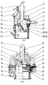
- the burner has the casing (1) in which the furnace chamber (2) is built-in. It is the "g” wooden gas generator which is connected to the jet burner (3) and combusted after mixing with the "p" secondary air.
- the jet burner (3) extends from the casing front wall (1) and through a mounting plate (4) is inserted into the space of the furnace chamber equipped with a combustion exhaust gas suction fan.
- the furnace chamber (2) has the basket grate (5) powered gravitationally by "bp" pellets through the vertical fill pipe (6) which is connected with a screw-conveyor not shown in the figure.
- the fill pipe (6) has been covered by a secondary air pipe (7) which has a forced draught fan (8) built-in at the inlet.
- the secondary air pipe (7) is connected with the jet burner (3) by an air chamber (9) above the furnace chamber (2).
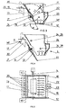
- the basket grate (5) is limited by fixed walls: two side walls (10) and the front wall (11) and the movable wall which is a uniform element composed of horizontal bottom wall (12) and oblique rear wall (13) rigidly connected at an "a" obtuse angle of approx. 130°.
- the "kd" front edge of the bottom wall (12) in the "A" extreme closed position of the grate (5) adheres to the "kp" lower edge of the front wall (11).
- the axis of revolution (14) is mounted, in bearings in the side walls (10) of the basket grate (5) and driven by the slipping clutch (15) and the actuator (16) of the motoreducer, mounted on the side wall of the casing (1).
- the rear wall (13) has a crevice air nozzle (17), placed parallel and below the axis of revolution (14) and directed to the bottom wall (12) of the basket grate (5).
- the corner zone of the bottom wall (12) connection with the rear wall (13) is cut by air gaps (18) directed perpendicular to the axis of revolution (14).
- the cleaning comb (19) with teeth (20) is placed according to air gaps (18) graduation.
- the front wall (11) has a bulge (22) circled by the "r2" internal radius from the axis of revolution (14), whereas the "kt" upper edge of the rear wall (13) in case of the rotation circles an arc with "r1" radius smaller by “s” moving crevice than the "r2" internal radius of the bulge (22).
- the front wall (11) in the middle of the bulge (22) width has a cavity (23) opened into the space of the grate (5), connected by a cable (24) with a blowing igniter (25) built-in on the side wall of the body (1).
- the lower level sensor (28) which operates at 36 kHz frequency has a measuring circuit located directly above the middle of the bottom wall (12) while the upper level sensor (29) which emits the electromagnetic wave at a frequency of 40 kHz is built-in nearby the "kt" upper edge of the rear wall (13) in the position of closed "A" basket grate (5) and under the fill pipe (6).
- the transmitters (30) and the receivers (31) of the level sensors (28 and 29) are placed at both sides of the casing (1) in the pipe casings (32) perforated with holes at sections projecting from the side walls of the casing (1).
- the pipe casings (32) are carried by thermal insulation layers (33) of the casing (1) to the furnace chamber (2) space, in coaxial positions with holes (34) in the side walls (10) of the basket grate (5).
- the programmed control module (26) starts the pellet feeder and the blowing igniter (25) as soon as it receives a "start" signal. After receiving the signal from the lower level of the sensor (28), the feeding will be stopped, and the subsequent loss of signal, which proves the lighting of pellets, initiates the turning off of the igniter (25) and the restart of feeding up to the signal level from the upper sensor (29).
- the controller maintains the pellet level between the lower (28) and upper (29) sensors. Simultaneously, the signals from the upper sensor (29) which capture single dropping pellets confirm information on the correct operation of the feeder.
- the software enforces cleaning activities of the air gaps (18) of the grate (5) by stoving the pellet layers and rotating the movable wall (12 and 13).
Landscapes
- Engineering & Computer Science (AREA)
- Chemical & Material Sciences (AREA)
- Combustion & Propulsion (AREA)
- Mechanical Engineering (AREA)
- General Engineering & Computer Science (AREA)
- Physics & Mathematics (AREA)
- Thermal Sciences (AREA)
- Solid-Fuel Combustion (AREA)
Claims (9)
- Brûleur à gazéification pour biocarburants, notamment les granulés de bois, comprenant un boîtier (1) avec une chambre de combustion (2) et un brûleur à jet (3) intégrés, le brûleur à jet (3) passant à travers une plaque de montage (4), la chambre de combustion (2) possédant une grille panier (5) alimentée par gravitation par le biais d'un tuyau de remplissage (6), la grille panier (5) est limitée par des parois fixes (10, 11) et une paroi mobile (12, 13) commandée à l'aide de l'actionneur (16) du mécanisme de nettoyage de la grille (5), le brûleur à gazéification pour biocarburants est en outre équipé d'un allumeur soufflant électrique (25) et d'un capteur du niveau de biocarburant supérieur (29) envoyant des signaux à un module de contrôle programmé, où le tuyau de remplissage (6) est couvert par un tuyau à air secondaire (7) connecté au brûleur à jet (3) par une chambre à air (9) divisée au-dessus de la chambre de combustion (2), caractérisé en ce que les parois fixes (10, 11) de la grille panier (5) comprennent deux parois latérales (10) et une paroi frontale (11), et que la paroi mobile (12, 13) de la grille panier (5) constitue un élément uniforme composé d'une paroi arrière (13) et d'une paroi inférieure (12) qui sont reliées sous un angle obtus (α), où le bord avant (kd) de la paroi inférieure (12) à l'extrémité (A) de la grille panier (5) adhère au bord inférieur de la paroi frontale (11),alors qu'à l'arrière, sur la paroi arrière (13) est fixé un axe de révolution (14), monté sur roulements au niveau des parois latérales (10) de la grille panier (5) et mu par l'actionneur (16) du mécanisme de nettoyage, où la connexion dans le coin entre la paroi inférieure (12) et la paroi arrière (13) de la grille panier (5) est entrecoupée par des ouvertures d'aération (18) dans le sens perpendiculaire à l'axe de révolution (14) et, derrière la paroi arrière (13) de la grille panier (5), se trouve monté un peigne de nettoyage (19) avec dents (20),et les dents (20) du peigne de nettoyage (19) sont placées en fonction de la position des ouvertures d'aération (18) sur la paroi mobile (12, 13) et après la rotation de la paroi mobile (12, 13) jusqu'à la position extrême d'ouverture (B) de la grille panier (5), les dents (20) du peigne 25 de nettoyage (19) pénètrent dans les ouvertures d'aération (18) de la paroi mobile (12, 13).
- Le brûleur conforme à la revendication 1, caractérisé en ce que la paroi frontale (11) possède un bombement (22) autour duquel tourne le (r2) rayon interne de l'axe de révolution (14), et le bord supérieur (kt) de la paroi arrière en rotation tourne autour d'un arc d'un (ri) rayon inférieur de (s) à la fente par rapport au (r2) rayon interne du bombement (22).
- Le brûleur conforme à la revendication 1, caractérisé en ce que les bords d'attaque des dents (20) du peigne de nettoyage (19) en perspective latérale sont inclinés en direction de du rayon allant de l'axe de révolution (14) et de préférence les bords d'attaque des dents (20) ont la courbe correspondant à la forme du quart supérieur d'une roue.
- Le brûleur conforme à la revendication 1, caractérisé en ce qu'il possède deux capteurs du niveau de biocarburant (28, 29) sur la grille (5), fonctionnant avec des rayons infra-rouges et leurs proprescodes de communication, où le capteur du niveau de biocarburant inférieur (28) possède un circuit de mesure situé directement au-dessus du milieu de la paroi inférieure (12) et le second - le capteur du niveau de biocarburant supérieur (29) est intégré près du bord supérieur de la (kt) paroi arrière en position fermée (A) de la grille (5) et en-dessous du tuyau de remplissage (6).
- Le brûleur conforme à la revendication 4,caractérisé en ce que lesémetteurs (30) et les récepteurs (31) des capteurs du niveau de biocarburant (28, 29) sont montés dans des tubes (32) avec des trous percés dans les parois latérales (1) du boîtier et dont l'autre extrémité est conduite à travers les couches d'isolation thermique (33) des parois latérales du boîtier (1) jusqu'à la chambre de combustion (2), en positions coaxiales par rapport aux trous (34) dans les parois latérales (10) de la grille (5).
- Le brûleur conforme à la revendication 1, caractérisée en ce que la paroi arrière (13) possède une buse à air pour fentes (17), parallèle à l'axe de révolution (14) et dirigée vers la paroi inférieure (12) de la grille (5).
- Le brûleur conforme à la revendication 1, caractérisé en ce qu'au niveau de la paroi frontale (11)vers lemilieu de la largeur du bombement (22), il y a une cavité (23) ouverte vers l'espace de la grille (5), connectée par câble (24) à l'allumeur soufflant (25) intégré à la paroi latérale du boîtier (1).
- Le brûleur conforme à la revendication 1, caractérisé en ce que l'axe de révolution (14) est connecté à l'actionneur (16) par un accouplement à friction (15).
- Le brûleur conforme à la revendication 1, caractérisé en ce qu'au niveau de l'entrée du tuyau à air secondaire(7), se trouve intégré un ventilateur à air soufflé (8).
Applications Claiming Priority (1)
| Application Number | Priority Date | Filing Date | Title |
|---|---|---|---|
| PL411542A PL231251B1 (pl) | 2015-03-11 | 2015-03-11 | Palnik zgazowanego biopaliwa, zwłaszcza pelletu drzewnego |
Publications (2)
| Publication Number | Publication Date |
|---|---|
| EP3088801A1 EP3088801A1 (fr) | 2016-11-02 |
| EP3088801B1 true EP3088801B1 (fr) | 2021-05-26 |
Family
ID=55524048
Family Applications (1)
| Application Number | Title | Priority Date | Filing Date |
|---|---|---|---|
| EP16000566.6A Active EP3088801B1 (fr) | 2015-03-11 | 2016-03-09 | Brûleur de biocarburant gazéifié, notamment pour des granulés de bois |
Country Status (2)
| Country | Link |
|---|---|
| EP (1) | EP3088801B1 (fr) |
| PL (1) | PL231251B1 (fr) |
Families Citing this family (1)
| Publication number | Priority date | Publication date | Assignee | Title |
|---|---|---|---|---|
| IT201800001147A1 (it) * | 2018-01-17 | 2019-07-17 | Rossofuoco Srl | Bruciatore perfezionato installabile su un dispositivo di riscaldamento per ambienti |
Citations (2)
| Publication number | Priority date | Publication date | Assignee | Title |
|---|---|---|---|---|
| GB2067742A (en) * | 1979-12-12 | 1981-07-30 | Melis F | Heating boiler with solid fuel |
| PL216981B1 (pl) * | 2010-08-20 | 2014-06-30 | Bogdan Baran | Wkład paleniskowy do pieca na drobnogranulowane paliwo stałe, zwłaszcza do kominka na pellety |
Family Cites Families (8)
| Publication number | Priority date | Publication date | Assignee | Title |
|---|---|---|---|---|
| GB191013640A (en) * | 1910-06-06 | 1911-03-30 | William Harold Booth | Improvements in Lifting and Adjustable Fire Grates for Kitchen Ranges and the like. |
| DE2830586C2 (de) | 1978-07-12 | 1987-05-07 | Glaswerk Schuller Gmbh, 6980 Wertheim | Verfahren und Vorrichtung zur Kühlung von Glasfäden |
| PL121906B1 (en) | 1978-07-19 | 1982-06-30 | Politechnika Slaska Im Wincent | Meter for measuring potential of electrodes in electrolytic tanks using commutation method vannakh po kommutacionnomu metodu |
| US20070215021A1 (en) * | 2003-04-09 | 2007-09-20 | Even Temp, Inc. | Apparatus and method for combustion |
| ITVI20040014A1 (it) | 2004-01-28 | 2004-04-28 | Thermorossi Spa | Bruciatore per stufe alimentari a pellets, cippato, cereali e scarti vegetali in genere |
| US7739966B2 (en) * | 2005-12-01 | 2010-06-22 | Janfire Ab | Device and method for the combustion of granular, solid fuel |
| PL208551B1 (pl) * | 2007-04-11 | 2011-05-31 | Leszek Janczy | Palnik na pelety do kotła centralnego ogrzewania |
| KR101295328B1 (ko) | 2012-06-11 | 2013-08-12 | 주식회사 경동나비엔 | 회전가능한 화격자 구조를 가지는 펠릿 보일러 |
-
2015
- 2015-03-11 PL PL411542A patent/PL231251B1/pl unknown
-
2016
- 2016-03-09 EP EP16000566.6A patent/EP3088801B1/fr active Active
Patent Citations (2)
| Publication number | Priority date | Publication date | Assignee | Title |
|---|---|---|---|---|
| GB2067742A (en) * | 1979-12-12 | 1981-07-30 | Melis F | Heating boiler with solid fuel |
| PL216981B1 (pl) * | 2010-08-20 | 2014-06-30 | Bogdan Baran | Wkład paleniskowy do pieca na drobnogranulowane paliwo stałe, zwłaszcza do kominka na pellety |
Also Published As
| Publication number | Publication date |
|---|---|
| PL231251B1 (pl) | 2019-02-28 |
| PL411542A1 (pl) | 2016-09-12 |
| EP3088801A1 (fr) | 2016-11-02 |
Similar Documents
| Publication | Publication Date | Title |
|---|---|---|
| EP2054675B1 (fr) | Chaudière | |
| US20110073101A1 (en) | Control system for heating systems | |
| EP2629007A2 (fr) | Appareil de combustion | |
| US20110136066A1 (en) | Bio-fuel furnace | |
| EP1277012B1 (fr) | Dispositif de combustion | |
| KR101634362B1 (ko) | 하향 연소식 펠렛난로 | |
| US7739966B2 (en) | Device and method for the combustion of granular, solid fuel | |
| JP5532443B2 (ja) | 加熱装置 | |
| EP3088801B1 (fr) | Brûleur de biocarburant gazéifié, notamment pour des granulés de bois | |
| RU2488037C1 (ru) | Водогрейный котел | |
| JP2010019539A (ja) | 熱風炉、加熱装置および加温機 | |
| RU122465U1 (ru) | Автоматизированный твердотопливный котел | |
| JP5030111B2 (ja) | 固形燃料燃焼装置の灰除去手段 | |
| RU115875U1 (ru) | Теплоэнергетический комплекс получения и подачи горячего воздуха для теплоснабжения вентиляции горных выработок и обогрева помещений большого объема (ангаров, складов, боксов) | |
| JP4912003B2 (ja) | 木質ペレット燃料燃焼装置 | |
| RU115050U1 (ru) | Водогрейный котел | |
| KR20130104395A (ko) | 사이클론 집진식 열교환기 구조의 고체연소 보일러 | |
| KR101448100B1 (ko) | 하이브리드 보일러 | |
| CN201636843U (zh) | 炉排式锅炉 | |
| EP2144001A1 (fr) | Appareil de nettoyage de l'âtre d'un appareil de chauffage | |
| US20080156312A1 (en) | Pellet stove | |
| CN202135688U (zh) | 常压蒸汽饲料熟化机 | |
| PL216981B1 (pl) | Wkład paleniskowy do pieca na drobnogranulowane paliwo stałe, zwłaszcza do kominka na pellety | |
| CN214370152U (zh) | 生物质颗粒燃烧器 | |
| PL67681Y1 (pl) | Palnik kotła grzewczego wodnego przystosowany do spalania biomasy |
Legal Events
| Date | Code | Title | Description |
|---|---|---|---|
| PUAI | Public reference made under article 153(3) epc to a published international application that has entered the european phase |
Free format text: ORIGINAL CODE: 0009012 |
|
| AK | Designated contracting states |
Kind code of ref document: A1 Designated state(s): AL AT BE BG CH CY CZ DE DK EE ES FI FR GB GR HR HU IE IS IT LI LT LU LV MC MK MT NL NO PL PT RO RS SE SI SK SM TR |
|
| AX | Request for extension of the european patent |
Extension state: BA ME |
|
| STAA | Information on the status of an ep patent application or granted ep patent |
Free format text: STATUS: REQUEST FOR EXAMINATION WAS MADE |
|
| 17P | Request for examination filed |
Effective date: 20170328 |
|
| RBV | Designated contracting states (corrected) |
Designated state(s): AL AT BE BG CH CY CZ DE DK EE ES FI FR GB GR HR HU IE IS IT LI LT LU LV MC MK MT NL NO PL PT RO RS SE SI SK SM TR |
|
| STAA | Information on the status of an ep patent application or granted ep patent |
Free format text: STATUS: EXAMINATION IS IN PROGRESS |
|
| 17Q | First examination report despatched |
Effective date: 20190424 |
|
| GRAP | Despatch of communication of intention to grant a patent |
Free format text: ORIGINAL CODE: EPIDOSNIGR1 |
|
| STAA | Information on the status of an ep patent application or granted ep patent |
Free format text: STATUS: GRANT OF PATENT IS INTENDED |
|
| GRAS | Grant fee paid |
Free format text: ORIGINAL CODE: EPIDOSNIGR3 |
|
| INTG | Intention to grant announced |
Effective date: 20210128 |
|
| RIN1 | Information on inventor provided before grant (corrected) |
Inventor name: ZAGRODNIK, SLAWOMIR Inventor name: JANCZY, LESZEK, JANCZY |
|
| GRAA | (expected) grant |
Free format text: ORIGINAL CODE: 0009210 |
|
| STAA | Information on the status of an ep patent application or granted ep patent |
Free format text: STATUS: THE PATENT HAS BEEN GRANTED |
|
| AK | Designated contracting states |
Kind code of ref document: B1 Designated state(s): AL AT BE BG CH CY CZ DE DK EE ES FI FR GB GR HR HU IE IS IT LI LT LU LV MC MK MT NL NO PL PT RO RS SE SI SK SM TR |
|
| REG | Reference to a national code |
Ref country code: GB Ref legal event code: FG4D |
|
| REG | Reference to a national code |
Ref country code: CH Ref legal event code: EP |
|
| REG | Reference to a national code |
Ref country code: AT Ref legal event code: REF Ref document number: 1396594 Country of ref document: AT Kind code of ref document: T Effective date: 20210615 |
|
| REG | Reference to a national code |
Ref country code: DE Ref legal event code: R096 Ref document number: 602016058298 Country of ref document: DE |
|
| REG | Reference to a national code |
Ref country code: IE Ref legal event code: FG4D |
|
| REG | Reference to a national code |
Ref country code: LT Ref legal event code: MG9D |
|
| PG25 | Lapsed in a contracting state [announced via postgrant information from national office to epo] |
Ref country code: LT Free format text: LAPSE BECAUSE OF FAILURE TO SUBMIT A TRANSLATION OF THE DESCRIPTION OR TO PAY THE FEE WITHIN THE PRESCRIBED TIME-LIMIT Effective date: 20210526 Ref country code: FI Free format text: LAPSE BECAUSE OF FAILURE TO SUBMIT A TRANSLATION OF THE DESCRIPTION OR TO PAY THE FEE WITHIN THE PRESCRIBED TIME-LIMIT Effective date: 20210526 Ref country code: HR Free format text: LAPSE BECAUSE OF FAILURE TO SUBMIT A TRANSLATION OF THE DESCRIPTION OR TO PAY THE FEE WITHIN THE PRESCRIBED TIME-LIMIT Effective date: 20210526 Ref country code: BG Free format text: LAPSE BECAUSE OF FAILURE TO SUBMIT A TRANSLATION OF THE DESCRIPTION OR TO PAY THE FEE WITHIN THE PRESCRIBED TIME-LIMIT Effective date: 20210826 |
|
| REG | Reference to a national code |
Ref country code: NL Ref legal event code: MP Effective date: 20210526 |
|
| REG | Reference to a national code |
Ref country code: AT Ref legal event code: EK Ref document number: 1396594 Country of ref document: AT Kind code of ref document: T Effective date: 20211004 |
|
| PG25 | Lapsed in a contracting state [announced via postgrant information from national office to epo] |
Ref country code: SE Free format text: LAPSE BECAUSE OF FAILURE TO SUBMIT A TRANSLATION OF THE DESCRIPTION OR TO PAY THE FEE WITHIN THE PRESCRIBED TIME-LIMIT Effective date: 20210526 Ref country code: RS Free format text: LAPSE BECAUSE OF FAILURE TO SUBMIT A TRANSLATION OF THE DESCRIPTION OR TO PAY THE FEE WITHIN THE PRESCRIBED TIME-LIMIT Effective date: 20210526 Ref country code: PL Free format text: LAPSE BECAUSE OF FAILURE TO SUBMIT A TRANSLATION OF THE DESCRIPTION OR TO PAY THE FEE WITHIN THE PRESCRIBED TIME-LIMIT Effective date: 20210526 Ref country code: PT Free format text: LAPSE BECAUSE OF FAILURE TO SUBMIT A TRANSLATION OF THE DESCRIPTION OR TO PAY THE FEE WITHIN THE PRESCRIBED TIME-LIMIT Effective date: 20210927 Ref country code: NO Free format text: LAPSE BECAUSE OF FAILURE TO SUBMIT A TRANSLATION OF THE DESCRIPTION OR TO PAY THE FEE WITHIN THE PRESCRIBED TIME-LIMIT Effective date: 20210826 Ref country code: GR Free format text: LAPSE BECAUSE OF FAILURE TO SUBMIT A TRANSLATION OF THE DESCRIPTION OR TO PAY THE FEE WITHIN THE PRESCRIBED TIME-LIMIT Effective date: 20210827 Ref country code: LV Free format text: LAPSE BECAUSE OF FAILURE TO SUBMIT A TRANSLATION OF THE DESCRIPTION OR TO PAY THE FEE WITHIN THE PRESCRIBED TIME-LIMIT Effective date: 20210526 Ref country code: IS Free format text: LAPSE BECAUSE OF FAILURE TO SUBMIT A TRANSLATION OF THE DESCRIPTION OR TO PAY THE FEE WITHIN THE PRESCRIBED TIME-LIMIT Effective date: 20210926 |
|
| REG | Reference to a national code |
Ref country code: SK Ref legal event code: T3 Ref document number: E 38264 Country of ref document: SK |
|
| REG | Reference to a national code |
Ref country code: SK Ref legal event code: TC4A Ref document number: E 38264 Country of ref document: SK Owner name: ZAGRODNIK, SLAWOMIR, WOJNICZ, PL Effective date: 20211214 Ref country code: SK Ref legal event code: TC4A Ref document number: E 38264 Country of ref document: SK Owner name: JANCZY, LESZEK, TARNOW, PL Effective date: 20211214 Ref country code: SK Ref legal event code: TC4A Ref document number: E 38264 Country of ref document: SK Owner name: TECH STEROWNIKI II SP. Z O.O., WIEPRZ, PL Effective date: 20211214 |
|
| REG | Reference to a national code |
Ref country code: DE Ref legal event code: R081 Ref document number: 602016058298 Country of ref document: DE Owner name: TECH STEROWNIKI II SP. Z O.O.., PL Free format text: FORMER OWNERS: LESZEK, JANCZY, TARNOW, PL; SLAWOMIR, ZAGRODNIK, WOJNICZ, PL; TECH STEROWNIKI SPOLKA Z OGRANICZONA ODPOWIEDZIALNOSCIA SPOLKA KOMANDYTOWA, WIEPRZ, PL Ref country code: DE Ref legal event code: R081 Ref document number: 602016058298 Country of ref document: DE Owner name: SLAWOMIR, ZAGRODNIK, PL Free format text: FORMER OWNERS: LESZEK, JANCZY, TARNOW, PL; SLAWOMIR, ZAGRODNIK, WOJNICZ, PL; TECH STEROWNIKI SPOLKA Z OGRANICZONA ODPOWIEDZIALNOSCIA SPOLKA KOMANDYTOWA, WIEPRZ, PL Ref country code: DE Ref legal event code: R081 Ref document number: 602016058298 Country of ref document: DE Owner name: LESZEK, JANCZY, PL Free format text: FORMER OWNERS: LESZEK, JANCZY, TARNOW, PL; SLAWOMIR, ZAGRODNIK, WOJNICZ, PL; TECH STEROWNIKI SPOLKA Z OGRANICZONA ODPOWIEDZIALNOSCIA SPOLKA KOMANDYTOWA, WIEPRZ, PL |
|
| PG25 | Lapsed in a contracting state [announced via postgrant information from national office to epo] |
Ref country code: NL Free format text: LAPSE BECAUSE OF FAILURE TO SUBMIT A TRANSLATION OF THE DESCRIPTION OR TO PAY THE FEE WITHIN THE PRESCRIBED TIME-LIMIT Effective date: 20210526 |
|
| PG25 | Lapsed in a contracting state [announced via postgrant information from national office to epo] |
Ref country code: EE Free format text: LAPSE BECAUSE OF FAILURE TO SUBMIT A TRANSLATION OF THE DESCRIPTION OR TO PAY THE FEE WITHIN THE PRESCRIBED TIME-LIMIT Effective date: 20210526 Ref country code: DK Free format text: LAPSE BECAUSE OF FAILURE TO SUBMIT A TRANSLATION OF THE DESCRIPTION OR TO PAY THE FEE WITHIN THE PRESCRIBED TIME-LIMIT Effective date: 20210526 Ref country code: SM Free format text: LAPSE BECAUSE OF FAILURE TO SUBMIT A TRANSLATION OF THE DESCRIPTION OR TO PAY THE FEE WITHIN THE PRESCRIBED TIME-LIMIT Effective date: 20210526 Ref country code: RO Free format text: LAPSE BECAUSE OF FAILURE TO SUBMIT A TRANSLATION OF THE DESCRIPTION OR TO PAY THE FEE WITHIN THE PRESCRIBED TIME-LIMIT Effective date: 20210526 Ref country code: ES Free format text: LAPSE BECAUSE OF FAILURE TO SUBMIT A TRANSLATION OF THE DESCRIPTION OR TO PAY THE FEE WITHIN THE PRESCRIBED TIME-LIMIT Effective date: 20210526 |
|
| REG | Reference to a national code |
Ref country code: DE Ref legal event code: R097 Ref document number: 602016058298 Country of ref document: DE |
|
| PLBE | No opposition filed within time limit |
Free format text: ORIGINAL CODE: 0009261 |
|
| STAA | Information on the status of an ep patent application or granted ep patent |
Free format text: STATUS: NO OPPOSITION FILED WITHIN TIME LIMIT |
|
| REG | Reference to a national code |
Ref country code: AT Ref legal event code: UEP Ref document number: 1396594 Country of ref document: AT Kind code of ref document: T Effective date: 20210526 Ref country code: AT Ref legal event code: HC Ref document number: 1396594 Country of ref document: AT Kind code of ref document: T Owner name: ZAGRODNIK, SLAWOMIR, PL Effective date: 20220302 Ref country code: AT Ref legal event code: HC Ref document number: 1396594 Country of ref document: AT Kind code of ref document: T Owner name: JANCZY, LESZEK, PL Effective date: 20220302 Ref country code: AT Ref legal event code: HC Ref document number: 1396594 Country of ref document: AT Kind code of ref document: T Owner name: TECH STEROWNIKI SP. Z.O.O. SP.K., PL Effective date: 20220302 |
|
| 26N | No opposition filed |
Effective date: 20220301 |
|
| PG25 | Lapsed in a contracting state [announced via postgrant information from national office to epo] |
Ref country code: IS Free format text: LAPSE BECAUSE OF FAILURE TO SUBMIT A TRANSLATION OF THE DESCRIPTION OR TO PAY THE FEE WITHIN THE PRESCRIBED TIME-LIMIT Effective date: 20210926 Ref country code: AL Free format text: LAPSE BECAUSE OF FAILURE TO SUBMIT A TRANSLATION OF THE DESCRIPTION OR TO PAY THE FEE WITHIN THE PRESCRIBED TIME-LIMIT Effective date: 20210526 |
|
| REG | Reference to a national code |
Ref country code: AT Ref legal event code: HC Ref document number: 1396594 Country of ref document: AT Kind code of ref document: T Owner name: ZAGRODNIK, SLAWOMIR, PL Effective date: 20220503 Ref country code: AT Ref legal event code: HC Ref document number: 1396594 Country of ref document: AT Kind code of ref document: T Owner name: JANCZY, LESZEK, PL Effective date: 20220503 Ref country code: AT Ref legal event code: HC Ref document number: 1396594 Country of ref document: AT Kind code of ref document: T Owner name: TECH STEROWNIKI II SP. Z O.O., PL Effective date: 20220503 |
|
| PG25 | Lapsed in a contracting state [announced via postgrant information from national office to epo] |
Ref country code: MC Free format text: LAPSE BECAUSE OF FAILURE TO SUBMIT A TRANSLATION OF THE DESCRIPTION OR TO PAY THE FEE WITHIN THE PRESCRIBED TIME-LIMIT Effective date: 20210526 |
|
| REG | Reference to a national code |
Ref country code: CH Ref legal event code: PL |
|
| GBPC | Gb: european patent ceased through non-payment of renewal fee |
Effective date: 20220309 |
|
| REG | Reference to a national code |
Ref country code: BE Ref legal event code: MM Effective date: 20220331 |
|
| PG25 | Lapsed in a contracting state [announced via postgrant information from national office to epo] |
Ref country code: LU Free format text: LAPSE BECAUSE OF NON-PAYMENT OF DUE FEES Effective date: 20220309 Ref country code: LI Free format text: LAPSE BECAUSE OF NON-PAYMENT OF DUE FEES Effective date: 20220331 Ref country code: IE Free format text: LAPSE BECAUSE OF NON-PAYMENT OF DUE FEES Effective date: 20220309 Ref country code: GB Free format text: LAPSE BECAUSE OF NON-PAYMENT OF DUE FEES Effective date: 20220309 Ref country code: FR Free format text: LAPSE BECAUSE OF NON-PAYMENT OF DUE FEES Effective date: 20220331 Ref country code: CH Free format text: LAPSE BECAUSE OF NON-PAYMENT OF DUE FEES Effective date: 20220331 |
|
| PG25 | Lapsed in a contracting state [announced via postgrant information from national office to epo] |
Ref country code: BE Free format text: LAPSE BECAUSE OF NON-PAYMENT OF DUE FEES Effective date: 20220331 |
|
| P01 | Opt-out of the competence of the unified patent court (upc) registered |
Effective date: 20230530 |
|
| PG25 | Lapsed in a contracting state [announced via postgrant information from national office to epo] |
Ref country code: HU Free format text: LAPSE BECAUSE OF FAILURE TO SUBMIT A TRANSLATION OF THE DESCRIPTION OR TO PAY THE FEE WITHIN THE PRESCRIBED TIME-LIMIT; INVALID AB INITIO Effective date: 20160309 |
|
| PG25 | Lapsed in a contracting state [announced via postgrant information from national office to epo] |
Ref country code: MK Free format text: LAPSE BECAUSE OF FAILURE TO SUBMIT A TRANSLATION OF THE DESCRIPTION OR TO PAY THE FEE WITHIN THE PRESCRIBED TIME-LIMIT Effective date: 20210526 Ref country code: CY Free format text: LAPSE BECAUSE OF FAILURE TO SUBMIT A TRANSLATION OF THE DESCRIPTION OR TO PAY THE FEE WITHIN THE PRESCRIBED TIME-LIMIT Effective date: 20210526 |
|
| PG25 | Lapsed in a contracting state [announced via postgrant information from national office to epo] |
Ref country code: TR Free format text: LAPSE BECAUSE OF FAILURE TO SUBMIT A TRANSLATION OF THE DESCRIPTION OR TO PAY THE FEE WITHIN THE PRESCRIBED TIME-LIMIT Effective date: 20210526 |
|
| PG25 | Lapsed in a contracting state [announced via postgrant information from national office to epo] |
Ref country code: MT Free format text: LAPSE BECAUSE OF FAILURE TO SUBMIT A TRANSLATION OF THE DESCRIPTION OR TO PAY THE FEE WITHIN THE PRESCRIBED TIME-LIMIT Effective date: 20210526 |
|
| PGFP | Annual fee paid to national office [announced via postgrant information from national office to epo] |
Ref country code: DE Payment date: 20250331 Year of fee payment: 10 |
|
| PGFP | Annual fee paid to national office [announced via postgrant information from national office to epo] |
Ref country code: AT Payment date: 20260330 Year of fee payment: 11 |
|
| PGFP | Annual fee paid to national office [announced via postgrant information from national office to epo] |
Ref country code: IT Payment date: 20260303 Year of fee payment: 11 |
|
| PGFP | Annual fee paid to national office [announced via postgrant information from national office to epo] |
Ref country code: CZ Payment date: 20260112 Year of fee payment: 11 |
|
| PGFP | Annual fee paid to national office [announced via postgrant information from national office to epo] |
Ref country code: SK Payment date: 20260112 Year of fee payment: 11 |