EP3089179B1 - Gehäuse für elektrische anlage mit einer doppelwand zu geräuschminderungszwecken - Google Patents
Gehäuse für elektrische anlage mit einer doppelwand zu geräuschminderungszwecken Download PDFInfo
- Publication number
- EP3089179B1 EP3089179B1 EP15165796.2A EP15165796A EP3089179B1 EP 3089179 B1 EP3089179 B1 EP 3089179B1 EP 15165796 A EP15165796 A EP 15165796A EP 3089179 B1 EP3089179 B1 EP 3089179B1
- Authority
- EP
- European Patent Office
- Prior art keywords
- wall
- stiffeners
- housing
- welded
- enclosure
- Prior art date
- Legal status (The legal status is an assumption and is not a legal conclusion. Google has not performed a legal analysis and makes no representation as to the accuracy of the status listed.)
- Active
Links
Images

Classifications
-
- H—ELECTRICITY
- H01—ELECTRIC ELEMENTS
- H01F—MAGNETS; INDUCTANCES; TRANSFORMERS; SELECTION OF MATERIALS FOR THEIR MAGNETIC PROPERTIES
- H01F27/00—Details of transformers or inductances, in general
- H01F27/33—Arrangements for noise damping
-
- H—ELECTRICITY
- H01—ELECTRIC ELEMENTS
- H01F—MAGNETS; INDUCTANCES; TRANSFORMERS; SELECTION OF MATERIALS FOR THEIR MAGNETIC PROPERTIES
- H01F27/00—Details of transformers or inductances, in general
- H01F27/02—Casings
Definitions
- the invention relates to noise reduction in electrical equipment such as power transformers, shunt reactors, series reactors or the like.
- This kind of electric equipment comprises an electric system encapsulated in a tank which is filled with dielectric gas for electric isolation or with an insulating fluid such as oil for transformer in order to provide electric isolation and cooling of the system.
- the noise is generated on one hand by the magnetostriction of magnetic material such as magnetic core which is subjected to alternating magnetic induction, and on the other hand by electromagnetic forces.
- the electromagnetic forces apply on parts of the equipment which carry electric currents or eddy currents and which are located inside a magnetic field.
- Such parts can be windings carrying electric currents, or metallic construction parts which do carry eddy currents as well.
- the harmonic content of frequencies in the noise are multiples of the power-frequency, i.e. the frequency of the power-current which is transferred in the equipment. It appears that especially the low frequencies noise beginning at the double of power-frequency, due to their long wavelengths, is very difficult to diminish.
- the noise which is generated by the magnetostriction and by the electromagnetic forces is transmitted to the environment of the tank through the structure and through the insulating fluid.
- the invention relates to a housing for an electric apparatus such as a transformer or reactor, comprising an enclosure delimiting an internal space intended to be filled with a medium such as dielectric gas or insulating oil, this enclosure comprising a top part, a bottom part, and a surrounding part surrounding all the internal space, comprising an inner wall and an outer wall arranged to define together a single intermediate volume extending at least all along the surrounding part, this intermediate volume being intended to isolate the noise generated by the electric system contained in the internal space, this housing comprising stiffeners at the inner face of the outer wall, characterized in that these stiffeners comprise each a main plate and a perpendicular plate welded to the main plate, and in that the outer wall is made of panels having their edges welded to the perpendicular plates of the outer stiffeners.
- the invention also relates to such a housing, wherein the intermediate volume is evacuated or filled with air at ambient pressure or with other fluid.
- the invention also relates to such a housing, where the outer side of the inner wall and/or the inner side of the outer wall is completely or partially covered with layers of acoustics absorbent material.
- the invention also relates to such a housing, comprising stiffeners to reinforce the inner wall.
- the invention also relates to such a housing, wherein the stiffeners are located at the outer face of the inner wall in order to be located in the intermediate volume.
- the invention also relates to such a housing, wherein the stiffeners of the outer wall comprise a main plate and a perpendicular plate welded to the main plate, and where the outer wall is made of panels having their edges welded to the perpendicular plates of the outer stiffeners.
- the invention also relates to such a housing, comprising at least one mechanical decoupling device mounted between the inner wall and the outer wall to reduce transmission of acoustic vibrations from the inner wall to the outer wall.
- the invention also relates to such a housing, wherein the inner wall and the outer wall comprise each a surrounding edge in the region of their top, and wherein at least one mechanical decoupling device is mounted between the surrounding edge of the inner wall and the surrounding edge of the outer wall.
- the invention also relates to such a housing, wherein the inner wall and the outer wall comprise each a bottom corresponding to the bottom part of the enclosure, and wherein at least one mechanical decoupling device is mounted between the bottom of the outer wall and the bottom of the inner wall.
- the invention also relates to such a housing, comprising at least one connection passing through the inner wall and the outer wall, at least one of these connections comprising an expansion joint having flanges secured at its extremities, these flanges being fixed respectively to the inner wall and to the outer wall.
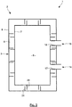
- the basic idea of the invention is to surround completely the lateral area of the tank with a double wall in all its surrounding portion, in order to eliminate the emission of sound in the lateral direction by creating an impedance break in the volume between this inner wall and outer wall.
- a tank 1 designed to enclose an electrical active part, made for example of magnetic core and windings which is not shown, comprises an enclosure 2 having a surrounding portion 3 and a bottom portion 4 integral with the surrounding portion 3 to form a base, which is open at its top and closed by a cover 5.
- This enclosure delimits an internal space 6 where the electrical active part which is not shown is to be mounted, this internal space 6 being filled with appropriate dielectric gas or fluid.
- the surrounding portion 3 together with the bottom portion 4 are made of an inside wall 7 and an outside wall 8, each having a surrounding and a bottom portion. These two walls 7 and 8 are spaced one from the other to delimit together a closed space 9 between them.
- the outer side of the inner wall 7 and/or the inner side of the outer wall 8 can be completely or partially covered with layers of an acoustics absorbent material 10.
- the material can be mineral fibers, perforated sheets of metallic material or any other material presenting appropriate acoustics absorption coefficient at frequencies of interest.
- the closed space 9 can be filled with air under normal pressure, with an appropriate gas under specific pressure, or it can also be evacuated to be under vacuum.
- the inside wall and the outside wall can be directly fixed to each other by a bolting system or the like.
- the bolts can be advantageously replaced by flexible couplings elements.
- the inside wall and the outside wall can advantageously be fixed one to the other, by means of mechanical decoupling devices 11.
- mechanical decoupling devices 11 ensure that vibration of the electric system transmitted to the inside wall 7 will not be transmitted to the outside wall 8, or at least strongly reduced.
- the mechanical decoupling devices 11 are the only link between the inside wall 7 and the outer wall 8, in order to provide a high decoupling level between the two walls, i.e. a high noise insulation.
- figure 1 it is one single mechanical decoupling device 11 which is mounted between the boarding edge 12 of the top of the inside wall 7 and the boarding edge 13 of the top of the outside wall 8, and this device 11 extends all along these edges 12, 13, on the four sides of the enclosure.
- the tank comprises a plurality of mechanical decoupling devices 11 which are interposed between the bottom part of the inside wall 7 and the bottom part of the outside wall 8, these elements being spaced apart ones from the others.
- the edges 12 and 13 of the inside wall 7 and of the outside wall 8 are fixed one to the other, and this connection can be made by flexible coupling elements. Despite the fact that the vibrations can be transmitted from the inside wall 7 to the outside wall 8 through the edges 12, 13, the vibrations of the outside wall are reduced by virtue of the decoupling devices 11.
- the tank comprises a plurality of connections, potentially distributed on the 4 lateral sides of the enclosure.
- Such connection marked as 14, 16 pass each through the lateral portion 3 of the enclosure, to allow circulation of a dielectric gas or insulating oil.
- Each connection 14, 16 comprises a respective tubular corrugated expansion joint 17, 18 mounted between the inside wall 7 and the outside wall 8.
- the connection can also be made with other kinds of soft materials.
- such a expansion joint 17 can be mounted with an inner flange 19 and an outer flange 21 welded each to a corresponding extremity of this joint 17.
- Each flange 19, 21 surrounds an extremity and extends perpendicular to the main direction of the extremity of the joint.
- the inner flange 19 is fixed to the outer face of the inner wall 7 by bolts 22 extending through this flange and screwed in the wall 7 or a corresponding plate welded to it.
- an adapter plate 23 is fixed to the outer face of outer wall 8 by bolts 24, to form a connecting portion of this outer wall 8.
- another outer part 26, which can be for example the flange of a valve of the system, is fixed to the adapter plate 23 and to the outer flange 21 by other bolts 27 which cross the outer part 26 and the adapting flange 23 and are screwed in the outer flange 21 of the joint 17.
- Dismounting the joint 17 from the tank is achieved by proceeding in the reverse order.
- expansion joints 17, 18 also ensure that thermal expansion changing the distance between the inside wall 7 and the outside wall 8 cannot damage the tank, and that the inside wall 7 and the outside wall 8 remain isolated from the transmission of vibrations from the inside wall to the outside wall. In other words these connections are insulated from noise.
- the walls of the tank are reinforced to withstand the difference of pressure existing between the internal volume, particularly when the intermediate volume is under vacuum.
- the internal enclosure of the tank is subjected to static pressure due to internal fluid presence for the inner wall 7, and to the external environment for the outer wall 8.
- the inner wall 7 comprises at its outer face a series of stiffening plates or beams 29 extending perpendicular to this outer face and welded to it in order to improve the rigidity of the inner wall 7, each stiffening plate 29 being spaced apart from the others.
- the stiffening plates 29 can be replaced by other stiffening elements having the shape of U, which can be filled with high density material.
- the outer wall 8 comprises at its inner but or outer face another series of stiffening plates or beams 31 perpendicular to the inner face and welded to it to improve its rigidity, these stiffening plates being spaced apart from each other.
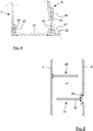
- All the stiffeners 29, 31 extend preferably inside the volume 9 which is between the inner wall 7 and the outer wall 8, since the stiffeners 29 of the inner wall 7 preferably extend at its outer face and since the stiffeners 31 of the outer wall 8 extend at its inner face, as seen in more detail in figure 5 .
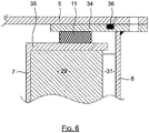
- the enclosure can comprise an outer upper flange 34 welded to the outer wall 8 and which surrounds all the top opening of the base of the enclosure, and an inner upper flange 35 welded to the inner wall 7 and which also surrounds all the top opening of the base enclosure.
- a decoupling device 11 can be provided between the inner top flange 35 and the outer top flange 34 which extends parallel and at a distance from each other, to ensure that these elements are isolated from each other. Since the hollow space 9 during operation is insulated, it is not necessary to apply anti corrosive coating in this space.
- the inner stiffeners 29 can be first welded to the outer face of the inner wall 7 and to the inner top flange 35 and to a corresponding bottom flange not represented but which is analog to the inner top flange 35. Then the outer stiffeners 31 can be welded to the outer wall 8 and to a bottom flange not shown on the drawings. The outer top flange 34 can be welded to the outer wall, once the stiffeners 31 have been welded to this outer wall.
- the outer stiffeners have advantageously a T shaped cross section as seen in figure 5 , comprising a main plate 32 fixed to a perpendicular plate 33.
- the main plate 32 extends parallel to the inner stiffeners 29 while the perpendicular plate 33 extends parallel to the outer wall of the tank.
- the outer wall can be welded to the outer stiffeners 31, installed at appropriate positions.
- the outer wall 8 can be made of rectangular panels which are welded to the perpendicular plate 33: each panel has an first edge welded to the outer face of the perpendicular plate 33 of an outer stiffener, and its other edge parallel to this first edge welded to the perpendicular plate of the next outer stiffener. Additionally, the two other edges of each panel can be welded to the top flange and to the bottom flange.
- the cover 5 is applied and fixed against the outer top flange 34 for example by bolts not visible in the figures. Additionally but not exclusively, an o-ring 36 provided in a groove at the top face of the outer top flange 34 ensures appropriate sealing between these two parts.
- the top surface of the tank can be equipped with a single wall, in order to radiate vibration energy only vertically since emission of noise in the vertical direction presents smaller environmental impact.
- the mechanical decoupling devices between the inner wall and the outer wall allow to reduce the transmission to the outer wall of the noise generated by electromagnetic forces acting on the inner wall or on the electric system which can be carried by the bottom of the inner wall.
- corrugated pipe section between the inner wall and the outer wall provides the same noise insulation between inner and outer wall.
- the use of vacuum permits to reach very important noise reduction targets, independently of the frequency radiated.
Landscapes
- Engineering & Computer Science (AREA)
- Power Engineering (AREA)
- Housings And Mounting Of Transformers (AREA)
Claims (8)
- Gehäuse (1) für eine elektrische Einrichtung, wie einen Transformator, das eine Kapselung (2) umfasst, die einen Innenraum (6) begrenzt, der dafür gedacht ist, mit einem Medium wie dielektrischem Gas oder isolierendem Öl gefüllt zu werden, wobei diese Kapselung (2) ein Oberteil (5), ein Bodenteil (4) und ein umlaufendes Teil (3), das den gesamten Innenraum (6) umgibt, umfasst, umfassend eine Innenwand (7) und eine Außenwand (8), die eingerichtet sind, gemeinsam ein einzelnes Zwischenvolumen (9) zu definieren, das sich mindestens entlang des gesamten umgebenden Teils erstreckt, wobei dieses Zwischenvolumen (9) dafür gedacht ist, den Lärm zu isolieren, der von dem elektrischen System erzeugt wird, das in dem Innenraum (6) enthalten ist, wobei das Gehäuse Außenversteifungen (31) an der Innenfläche der Außenwand (8) umfasst, dadurch gekennzeichnet, dass diese Außenversteifungen (31) jeweils eine Hauptplatte (32) und eine senkrechte Platte (33), die an die Hauptplatte (32) geschweißt ist, umfassen, und dadurch, dass die Außenwand (8) aus Tafeln hergestellt ist, deren Kanten an die senkrechten Platten (33) der Außenversteifungen (31) geschweißt sind.
- Gehäuse (1) nach Anspruch 1, wobei das Zwischenvolumen geleert oder mit Luft bei Umgebungsdruck oder einem anderen Fluid gefüllt ist.
- Gehäuse nach Anspruch 1 oder 2, wo die Außenseite der Innenwand (7) und/oder die Innenseite der Außenwand (8) vollständig oder teilweise mit Schichten von akustisch absorbierendem Material (10) bedeckt ist.
- Gehäuse nach einem der vorstehenden Ansprüche, umfassend Innenversteifungen (29), um die Innenwand (7) zu verstärken, die an der Außenfläche der Innenwand (7) liegt, um in dem Zwischenvolumen (9) zu liegen.
- Gehäuse nach einem der vorstehenden Ansprüche, umfassend mindestens eine mechanische Entkopplungsvorrichtung (11), die zwischen der Innenwand (7) und der Außenwand (8) montiert ist, um eine Übertragung von akustischen Schwingungen von der Innenwand (7) an die Außenwand (8) zu verringern.
- Gehäuse nach Anspruch 5, wobei die Innenwand (7) und die Außenwand (8) jeweils eine umgebende Kante (12, 13) in dem Bereich derer Oberseite umfassen und wobei die mindestens eine mechanische Entkopplungsvorrichtung (11) zwischen der umgebenden Kante (12) der Innenwand (7) und der umgebenden Kante (13) der Außenwand (8) montiert ist.
- Gehäuse nach Anspruch 5, wobei die Innenwand (7) und die Außenwand (8) jeweils einen Boden umfassen, der dem Bodenteil (4) der Kapselung (2) entspricht, und wobei die mindestens eine mechanische Entkopplungsvorrichtung (11) zwischen dem Boden der Außenwand (8) und dem Boden der Innenwand (7) montiert ist.
- Gehäuse nach einem der vorstehenden Ansprüche, umfassend mindestens eine Verbindung (14, 16), die durch die Innenwand (7) und die Außenwand (8) geht, wobei mindestens eine dieser Verbindungen (14, 16) eine Dehnfuge (17) umfasst, die Flansche (19, 21) an ihre Extremitäten geschweißt aufweist, wobei diese Flansche an der Innenwand (7) bzw. an der Außenwand (8) fixiert sind.
Priority Applications (1)
| Application Number | Priority Date | Filing Date | Title |
|---|---|---|---|
| EP15165796.2A EP3089179B1 (de) | 2015-04-29 | 2015-04-29 | Gehäuse für elektrische anlage mit einer doppelwand zu geräuschminderungszwecken |
Applications Claiming Priority (1)
| Application Number | Priority Date | Filing Date | Title |
|---|---|---|---|
| EP15165796.2A EP3089179B1 (de) | 2015-04-29 | 2015-04-29 | Gehäuse für elektrische anlage mit einer doppelwand zu geräuschminderungszwecken |
Publications (2)
| Publication Number | Publication Date |
|---|---|
| EP3089179A1 EP3089179A1 (de) | 2016-11-02 |
| EP3089179B1 true EP3089179B1 (de) | 2020-10-21 |
Family
ID=53039307
Family Applications (1)
| Application Number | Title | Priority Date | Filing Date |
|---|---|---|---|
| EP15165796.2A Active EP3089179B1 (de) | 2015-04-29 | 2015-04-29 | Gehäuse für elektrische anlage mit einer doppelwand zu geräuschminderungszwecken |
Country Status (1)
| Country | Link |
|---|---|
| EP (1) | EP3089179B1 (de) |
Cited By (1)
| Publication number | Priority date | Publication date | Assignee | Title |
|---|---|---|---|---|
| EP4492416A3 (de) * | 2022-02-17 | 2026-02-11 | TDK Electronics AG | Kondensator, verfahren zu seiner herstellung und seine verwendung |
Families Citing this family (7)
| Publication number | Priority date | Publication date | Assignee | Title |
|---|---|---|---|---|
| GB2548139B (en) * | 2016-03-10 | 2020-03-18 | General Electric Technology Gmbh | Improvements in or relating to sound reduction components for housings |
| DE102017220782A1 (de) | 2017-11-21 | 2019-05-23 | Siemens Aktiengesellschaft | Transformator zur Befestigung an einem Mast eines Energieverteilungsnetzes |
| CN108335882A (zh) * | 2017-11-29 | 2018-07-27 | 无锡澳蓝特环保科技有限公司 | 变电站排气口用静压机构 |
| DE102018119216B4 (de) * | 2018-08-07 | 2020-07-23 | Tdk Electronics Ag | Gehäuse für eine elektronische Komponente mit einem Innenbehälter und einer Außenumhüllung |
| EP3764377A1 (de) * | 2019-07-09 | 2021-01-13 | ABB Schweiz AG | Tank für einen flüssigkeitsgefüllten manteltransformator oder mantelreaktor |
| CN112750601A (zh) * | 2019-10-30 | 2021-05-04 | 中国电力科学研究院有限公司 | 一种低噪声变压器油箱 |
| CN116313410B (zh) * | 2023-04-11 | 2023-11-21 | 广东南桂起重机械有限公司 | 一种降噪变压器油箱外壳 |
Family Cites Families (6)
| Publication number | Priority date | Publication date | Assignee | Title |
|---|---|---|---|---|
| US2734096A (en) * | 1956-02-07 | Electric transformers and like | ||
| US1846887A (en) * | 1930-05-24 | 1932-02-23 | Gen Electric | Electrical induction apparatus |
| GB444129A (en) * | 1934-12-11 | 1936-03-16 | English Electric Co Ltd | Means for reducing noise from electric transformers or like apparatus contained in tanks |
| US3260974A (en) * | 1963-09-12 | 1966-07-12 | Westinghouse Electric Corp | Noise reducing means for electrical apparatus |
| JPS5740908A (en) * | 1980-08-25 | 1982-03-06 | Kansai Electric Power Co Inc:The | Container for stationary electric apparatus |
| KR101944967B1 (ko) * | 2012-06-05 | 2019-02-01 | 지멘스 악티엔게젤샤프트 | 액체 충전 변압기 또는 인덕터용 탱크 |
-
2015
- 2015-04-29 EP EP15165796.2A patent/EP3089179B1/de active Active
Non-Patent Citations (1)
| Title |
|---|
| None * |
Cited By (1)
| Publication number | Priority date | Publication date | Assignee | Title |
|---|---|---|---|---|
| EP4492416A3 (de) * | 2022-02-17 | 2026-02-11 | TDK Electronics AG | Kondensator, verfahren zu seiner herstellung und seine verwendung |
Also Published As
| Publication number | Publication date |
|---|---|
| EP3089179A1 (de) | 2016-11-02 |
Similar Documents
| Publication | Publication Date | Title |
|---|---|---|
| EP3089179B1 (de) | Gehäuse für elektrische anlage mit einer doppelwand zu geräuschminderungszwecken | |
| US3451503A (en) | Sound-reducing housing for alternating current electric apparatus | |
| EP2570585A1 (de) | Unterwassertransformator | |
| KR20160026099A (ko) | 변압기 외함 소음 저감장치 | |
| CN106663520A (zh) | 牵引变压器 | |
| CN103635068B (zh) | 能量转换系统的电磁屏蔽结构和相关方法 | |
| KR20140037623A (ko) | 변압기용 외함 | |
| KR20230146934A (ko) | 절연 및 유도가열방지 성능이 우수한 단일 패키징 타입 반도체 변압기용 서브모듈 | |
| US20160133382A1 (en) | Stationary Induction Apparatus | |
| US9824814B2 (en) | Acoustic panels for transformers | |
| KR20080036034A (ko) | 저소음 이중외함변압기 | |
| CN111771249A (zh) | 用于充液壳式变压器或壳式电抗器的箱体 | |
| US20170047154A1 (en) | High Capacity Power Transformer Housing With a Noise Shielding Structure | |
| JP2014175627A (ja) | 変圧器 | |
| TW201621938A (zh) | 靜止感應電器 | |
| JP5580688B2 (ja) | 地上設置型変圧器装置 | |
| CN115638111A (zh) | 用于大排量螺杆压缩机的隔声罩 | |
| CN107240872B (zh) | 一种户外电力设备箱体及其降噪方法 | |
| WO2018131179A1 (ja) | スイッチギヤ | |
| US20240055179A1 (en) | Power transformer having a noise reduction function | |
| JP2015023167A (ja) | 静止誘導電器 | |
| JP2015070182A (ja) | 静止誘導電器 | |
| CN209388894U (zh) | 电气装置和带有冷却装置的电气设备 | |
| CN114072887B (zh) | 用于充液壳式变压器或壳式电抗器的箱体 | |
| JPH0722257A (ja) | 静止誘導電器 |
Legal Events
| Date | Code | Title | Description |
|---|---|---|---|
| PUAI | Public reference made under article 153(3) epc to a published international application that has entered the european phase |
Free format text: ORIGINAL CODE: 0009012 |
|
| AK | Designated contracting states |
Kind code of ref document: A1 Designated state(s): AL AT BE BG CH CY CZ DE DK EE ES FI FR GB GR HR HU IE IS IT LI LT LU LV MC MK MT NL NO PL PT RO RS SE SI SK SM TR |
|
| AX | Request for extension of the european patent |
Extension state: BA ME |
|
| STAA | Information on the status of an ep patent application or granted ep patent |
Free format text: STATUS: REQUEST FOR EXAMINATION WAS MADE |
|
| 17P | Request for examination filed |
Effective date: 20170410 |
|
| RBV | Designated contracting states (corrected) |
Designated state(s): AL AT BE BG CH CY CZ DE DK EE ES FI FR GB GR HR HU IE IS IT LI LT LU LV MC MK MT NL NO PL PT RO RS SE SI SK SM TR |
|
| RIC1 | Information provided on ipc code assigned before grant |
Ipc: H01F 27/02 20060101AFI20200218BHEP Ipc: H01F 27/33 20060101ALI20200218BHEP |
|
| GRAP | Despatch of communication of intention to grant a patent |
Free format text: ORIGINAL CODE: EPIDOSNIGR1 |
|
| STAA | Information on the status of an ep patent application or granted ep patent |
Free format text: STATUS: GRANT OF PATENT IS INTENDED |
|
| INTG | Intention to grant announced |
Effective date: 20200518 |
|
| RIN1 | Information on inventor provided before grant (corrected) |
Inventor name: GILLET, MAX Inventor name: ROESNER, MICHAEL |
|
| GRAS | Grant fee paid |
Free format text: ORIGINAL CODE: EPIDOSNIGR3 |
|
| GRAA | (expected) grant |
Free format text: ORIGINAL CODE: 0009210 |
|
| STAA | Information on the status of an ep patent application or granted ep patent |
Free format text: STATUS: THE PATENT HAS BEEN GRANTED |
|
| AK | Designated contracting states |
Kind code of ref document: B1 Designated state(s): AL AT BE BG CH CY CZ DE DK EE ES FI FR GB GR HR HU IE IS IT LI LT LU LV MC MK MT NL NO PL PT RO RS SE SI SK SM TR |
|
| REG | Reference to a national code |
Ref country code: GB Ref legal event code: FG4D |
|
| REG | Reference to a national code |
Ref country code: CH Ref legal event code: EP |
|
| REG | Reference to a national code |
Ref country code: DE Ref legal event code: R096 Ref document number: 602015060689 Country of ref document: DE |
|
| REG | Reference to a national code |
Ref country code: IE Ref legal event code: FG4D |
|
| REG | Reference to a national code |
Ref country code: AT Ref legal event code: REF Ref document number: 1326687 Country of ref document: AT Kind code of ref document: T Effective date: 20201115 |
|
| REG | Reference to a national code |
Ref country code: SE Ref legal event code: TRGR |
|
| REG | Reference to a national code |
Ref country code: AT Ref legal event code: MK05 Ref document number: 1326687 Country of ref document: AT Kind code of ref document: T Effective date: 20201021 |
|
| REG | Reference to a national code |
Ref country code: NL Ref legal event code: MP Effective date: 20201021 |
|
| PG25 | Lapsed in a contracting state [announced via postgrant information from national office to epo] |
Ref country code: RS Free format text: LAPSE BECAUSE OF FAILURE TO SUBMIT A TRANSLATION OF THE DESCRIPTION OR TO PAY THE FEE WITHIN THE PRESCRIBED TIME-LIMIT Effective date: 20201021 Ref country code: FI Free format text: LAPSE BECAUSE OF FAILURE TO SUBMIT A TRANSLATION OF THE DESCRIPTION OR TO PAY THE FEE WITHIN THE PRESCRIBED TIME-LIMIT Effective date: 20201021 Ref country code: NO Free format text: LAPSE BECAUSE OF FAILURE TO SUBMIT A TRANSLATION OF THE DESCRIPTION OR TO PAY THE FEE WITHIN THE PRESCRIBED TIME-LIMIT Effective date: 20210121 Ref country code: NL Free format text: LAPSE BECAUSE OF FAILURE TO SUBMIT A TRANSLATION OF THE DESCRIPTION OR TO PAY THE FEE WITHIN THE PRESCRIBED TIME-LIMIT Effective date: 20201021 Ref country code: PT Free format text: LAPSE BECAUSE OF FAILURE TO SUBMIT A TRANSLATION OF THE DESCRIPTION OR TO PAY THE FEE WITHIN THE PRESCRIBED TIME-LIMIT Effective date: 20210222 Ref country code: GR Free format text: LAPSE BECAUSE OF FAILURE TO SUBMIT A TRANSLATION OF THE DESCRIPTION OR TO PAY THE FEE WITHIN THE PRESCRIBED TIME-LIMIT Effective date: 20210122 |
|
| REG | Reference to a national code |
Ref country code: LT Ref legal event code: MG4D |
|
| PG25 | Lapsed in a contracting state [announced via postgrant information from national office to epo] |
Ref country code: LV Free format text: LAPSE BECAUSE OF FAILURE TO SUBMIT A TRANSLATION OF THE DESCRIPTION OR TO PAY THE FEE WITHIN THE PRESCRIBED TIME-LIMIT Effective date: 20201021 Ref country code: IS Free format text: LAPSE BECAUSE OF FAILURE TO SUBMIT A TRANSLATION OF THE DESCRIPTION OR TO PAY THE FEE WITHIN THE PRESCRIBED TIME-LIMIT Effective date: 20210221 Ref country code: PL Free format text: LAPSE BECAUSE OF FAILURE TO SUBMIT A TRANSLATION OF THE DESCRIPTION OR TO PAY THE FEE WITHIN THE PRESCRIBED TIME-LIMIT Effective date: 20201021 Ref country code: BG Free format text: LAPSE BECAUSE OF FAILURE TO SUBMIT A TRANSLATION OF THE DESCRIPTION OR TO PAY THE FEE WITHIN THE PRESCRIBED TIME-LIMIT Effective date: 20210121 Ref country code: AT Free format text: LAPSE BECAUSE OF FAILURE TO SUBMIT A TRANSLATION OF THE DESCRIPTION OR TO PAY THE FEE WITHIN THE PRESCRIBED TIME-LIMIT Effective date: 20201021 Ref country code: ES Free format text: LAPSE BECAUSE OF FAILURE TO SUBMIT A TRANSLATION OF THE DESCRIPTION OR TO PAY THE FEE WITHIN THE PRESCRIBED TIME-LIMIT Effective date: 20201021 |
|
| PG25 | Lapsed in a contracting state [announced via postgrant information from national office to epo] |
Ref country code: HR Free format text: LAPSE BECAUSE OF FAILURE TO SUBMIT A TRANSLATION OF THE DESCRIPTION OR TO PAY THE FEE WITHIN THE PRESCRIBED TIME-LIMIT Effective date: 20201021 |
|
| REG | Reference to a national code |
Ref country code: DE Ref legal event code: R097 Ref document number: 602015060689 Country of ref document: DE |
|
| PG25 | Lapsed in a contracting state [announced via postgrant information from national office to epo] |
Ref country code: LT Free format text: LAPSE BECAUSE OF FAILURE TO SUBMIT A TRANSLATION OF THE DESCRIPTION OR TO PAY THE FEE WITHIN THE PRESCRIBED TIME-LIMIT Effective date: 20201021 Ref country code: RO Free format text: LAPSE BECAUSE OF FAILURE TO SUBMIT A TRANSLATION OF THE DESCRIPTION OR TO PAY THE FEE WITHIN THE PRESCRIBED TIME-LIMIT Effective date: 20201021 Ref country code: SK Free format text: LAPSE BECAUSE OF FAILURE TO SUBMIT A TRANSLATION OF THE DESCRIPTION OR TO PAY THE FEE WITHIN THE PRESCRIBED TIME-LIMIT Effective date: 20201021 Ref country code: SM Free format text: LAPSE BECAUSE OF FAILURE TO SUBMIT A TRANSLATION OF THE DESCRIPTION OR TO PAY THE FEE WITHIN THE PRESCRIBED TIME-LIMIT Effective date: 20201021 Ref country code: CZ Free format text: LAPSE BECAUSE OF FAILURE TO SUBMIT A TRANSLATION OF THE DESCRIPTION OR TO PAY THE FEE WITHIN THE PRESCRIBED TIME-LIMIT Effective date: 20201021 Ref country code: EE Free format text: LAPSE BECAUSE OF FAILURE TO SUBMIT A TRANSLATION OF THE DESCRIPTION OR TO PAY THE FEE WITHIN THE PRESCRIBED TIME-LIMIT Effective date: 20201021 |
|
| PLBE | No opposition filed within time limit |
Free format text: ORIGINAL CODE: 0009261 |
|
| STAA | Information on the status of an ep patent application or granted ep patent |
Free format text: STATUS: NO OPPOSITION FILED WITHIN TIME LIMIT |
|
| PG25 | Lapsed in a contracting state [announced via postgrant information from national office to epo] |
Ref country code: DK Free format text: LAPSE BECAUSE OF FAILURE TO SUBMIT A TRANSLATION OF THE DESCRIPTION OR TO PAY THE FEE WITHIN THE PRESCRIBED TIME-LIMIT Effective date: 20201021 |
|
| 26N | No opposition filed |
Effective date: 20210722 |
|
| PG25 | Lapsed in a contracting state [announced via postgrant information from national office to epo] |
Ref country code: IT Free format text: LAPSE BECAUSE OF FAILURE TO SUBMIT A TRANSLATION OF THE DESCRIPTION OR TO PAY THE FEE WITHIN THE PRESCRIBED TIME-LIMIT Effective date: 20201021 Ref country code: AL Free format text: LAPSE BECAUSE OF FAILURE TO SUBMIT A TRANSLATION OF THE DESCRIPTION OR TO PAY THE FEE WITHIN THE PRESCRIBED TIME-LIMIT Effective date: 20201021 |
|
| PG25 | Lapsed in a contracting state [announced via postgrant information from national office to epo] |
Ref country code: SI Free format text: LAPSE BECAUSE OF FAILURE TO SUBMIT A TRANSLATION OF THE DESCRIPTION OR TO PAY THE FEE WITHIN THE PRESCRIBED TIME-LIMIT Effective date: 20201021 Ref country code: MC Free format text: LAPSE BECAUSE OF FAILURE TO SUBMIT A TRANSLATION OF THE DESCRIPTION OR TO PAY THE FEE WITHIN THE PRESCRIBED TIME-LIMIT Effective date: 20201021 |
|
| PG25 | Lapsed in a contracting state [announced via postgrant information from national office to epo] |
Ref country code: LU Free format text: LAPSE BECAUSE OF NON-PAYMENT OF DUE FEES Effective date: 20210429 |
|
| REG | Reference to a national code |
Ref country code: BE Ref legal event code: MM Effective date: 20210430 |
|
| PG25 | Lapsed in a contracting state [announced via postgrant information from national office to epo] |
Ref country code: LI Free format text: LAPSE BECAUSE OF NON-PAYMENT OF DUE FEES Effective date: 20210430 Ref country code: FR Free format text: LAPSE BECAUSE OF NON-PAYMENT OF DUE FEES Effective date: 20210430 Ref country code: CH Free format text: LAPSE BECAUSE OF NON-PAYMENT OF DUE FEES Effective date: 20210430 |
|
| PG25 | Lapsed in a contracting state [announced via postgrant information from national office to epo] |
Ref country code: IE Free format text: LAPSE BECAUSE OF NON-PAYMENT OF DUE FEES Effective date: 20210429 |
|
| PG25 | Lapsed in a contracting state [announced via postgrant information from national office to epo] |
Ref country code: IS Free format text: LAPSE BECAUSE OF FAILURE TO SUBMIT A TRANSLATION OF THE DESCRIPTION OR TO PAY THE FEE WITHIN THE PRESCRIBED TIME-LIMIT Effective date: 20210221 |
|
| PG25 | Lapsed in a contracting state [announced via postgrant information from national office to epo] |
Ref country code: BE Free format text: LAPSE BECAUSE OF NON-PAYMENT OF DUE FEES Effective date: 20210430 |
|
| PG25 | Lapsed in a contracting state [announced via postgrant information from national office to epo] |
Ref country code: HU Free format text: LAPSE BECAUSE OF FAILURE TO SUBMIT A TRANSLATION OF THE DESCRIPTION OR TO PAY THE FEE WITHIN THE PRESCRIBED TIME-LIMIT; INVALID AB INITIO Effective date: 20150429 |
|
| P01 | Opt-out of the competence of the unified patent court (upc) registered |
Effective date: 20230522 |
|
| PG25 | Lapsed in a contracting state [announced via postgrant information from national office to epo] |
Ref country code: CY Free format text: LAPSE BECAUSE OF FAILURE TO SUBMIT A TRANSLATION OF THE DESCRIPTION OR TO PAY THE FEE WITHIN THE PRESCRIBED TIME-LIMIT Effective date: 20201021 |
|
| PG25 | Lapsed in a contracting state [announced via postgrant information from national office to epo] |
Ref country code: MK Free format text: LAPSE BECAUSE OF FAILURE TO SUBMIT A TRANSLATION OF THE DESCRIPTION OR TO PAY THE FEE WITHIN THE PRESCRIBED TIME-LIMIT Effective date: 20201021 |
|
| PG25 | Lapsed in a contracting state [announced via postgrant information from national office to epo] |
Ref country code: TR Free format text: LAPSE BECAUSE OF FAILURE TO SUBMIT A TRANSLATION OF THE DESCRIPTION OR TO PAY THE FEE WITHIN THE PRESCRIBED TIME-LIMIT Effective date: 20201021 |
|
| PG25 | Lapsed in a contracting state [announced via postgrant information from national office to epo] |
Ref country code: MT Free format text: LAPSE BECAUSE OF FAILURE TO SUBMIT A TRANSLATION OF THE DESCRIPTION OR TO PAY THE FEE WITHIN THE PRESCRIBED TIME-LIMIT Effective date: 20201021 |
|
| PGFP | Annual fee paid to national office [announced via postgrant information from national office to epo] |
Ref country code: DE Payment date: 20250319 Year of fee payment: 11 |
|
| PGFP | Annual fee paid to national office [announced via postgrant information from national office to epo] |
Ref country code: SE Payment date: 20260319 Year of fee payment: 12 |
|
| PGFP | Annual fee paid to national office [announced via postgrant information from national office to epo] |
Ref country code: GB Payment date: 20260319 Year of fee payment: 12 |