EP3089351B1 - Verfahren zur bestimmung der position eines rotors eines permanentmagnetservomotors - Google Patents
Verfahren zur bestimmung der position eines rotors eines permanentmagnetservomotors Download PDFInfo
- Publication number
- EP3089351B1 EP3089351B1 EP16000903.1A EP16000903A EP3089351B1 EP 3089351 B1 EP3089351 B1 EP 3089351B1 EP 16000903 A EP16000903 A EP 16000903A EP 3089351 B1 EP3089351 B1 EP 3089351B1
- Authority
- EP
- European Patent Office
- Prior art keywords
- rotor
- current
- saturation
- determined
- synchronous motor
- Prior art date
- Legal status (The legal status is an assumption and is not a legal conclusion. Google has not performed a legal analysis and makes no representation as to the accuracy of the status listed.)
- Revoked
Links
Images




Classifications
-
- H—ELECTRICITY
- H02—GENERATION; CONVERSION OR DISTRIBUTION OF ELECTRIC POWER
- H02P—CONTROL OR REGULATION OF ELECTRIC MOTORS, ELECTRIC GENERATORS OR DYNAMO-ELECTRIC CONVERTERS; CONTROLLING TRANSFORMERS, REACTORS OR CHOKE COILS
- H02P6/00—Arrangements for controlling synchronous motors or other dynamo-electric motors using electronic commutation dependent on the rotor position; Electronic commutators therefor
- H02P6/14—Electronic commutators
- H02P6/16—Circuit arrangements for detecting position
- H02P6/18—Circuit arrangements for detecting position without separate position detecting elements
-
- H—ELECTRICITY
- H02—GENERATION; CONVERSION OR DISTRIBUTION OF ELECTRIC POWER
- H02P—CONTROL OR REGULATION OF ELECTRIC MOTORS, ELECTRIC GENERATORS OR DYNAMO-ELECTRIC CONVERTERS; CONTROLLING TRANSFORMERS, REACTORS OR CHOKE COILS
- H02P21/00—Arrangements or methods for the control of electric machines by vector control, e.g. by control of field orientation
- H02P21/24—Vector control not involving the use of rotor position or rotor speed sensors
-
- H—ELECTRICITY
- H02—GENERATION; CONVERSION OR DISTRIBUTION OF ELECTRIC POWER
- H02P—CONTROL OR REGULATION OF ELECTRIC MOTORS, ELECTRIC GENERATORS OR DYNAMO-ELECTRIC CONVERTERS; CONTROLLING TRANSFORMERS, REACTORS OR CHOKE COILS
- H02P25/00—Arrangements or methods for the control of AC motors characterised by the kind of AC motor or by structural details
- H02P25/02—Arrangements or methods for the control of AC motors characterised by the kind of AC motor or by structural details characterised by the kind of motor
- H02P25/022—Synchronous motors
- H02P25/024—Synchronous motors controlled by supply frequency
-
- H—ELECTRICITY
- H02—GENERATION; CONVERSION OR DISTRIBUTION OF ELECTRIC POWER
- H02P—CONTROL OR REGULATION OF ELECTRIC MOTORS, ELECTRIC GENERATORS OR DYNAMO-ELECTRIC CONVERTERS; CONTROLLING TRANSFORMERS, REACTORS OR CHOKE COILS
- H02P6/00—Arrangements for controlling synchronous motors or other dynamo-electric motors using electronic commutation dependent on the rotor position; Electronic commutators therefor
- H02P6/14—Electronic commutators
- H02P6/16—Circuit arrangements for detecting position
- H02P6/18—Circuit arrangements for detecting position without separate position detecting elements
- H02P6/183—Circuit arrangements for detecting position without separate position detecting elements using an injected high frequency signal
Definitions
- the invention relates to a method for determining the position of a rotor of a permanent magnet servomotor according to the preamble of claim 1.
- Position encoders are used to determine the position of a rotor of an electric motor. They are connected to a microcontroller using an encoder cable. The position encoders are expensive components that make the corresponding drive more expensive. The evaluation electronics of such encoders as well as the cabling are also sensitive and prone to failure in use.
- the invention is based on the object of designing the generic method in such a way that a reliable determination of the position of the rotor is achieved with an inexpensive design.
- the servo drive is characterized by the fact that a position encoder is no longer required to determine the position of the rotor.
- the current test signal is injected in certain operating states.
- the rotor position can be determined simply and yet precisely via the measured current that then sets in.
- the rotor position can be used both for commutation and for speed and position control.
- the current test signal is advantageously supplied via the actuator, which is preferably a power electronics of the servo drive.
- the motor is a permanent magnet synchronous motor.
- the current space vector is determined using the vector diagram associated with the current resulting from the injection of the test signal. Based on the angular position of the current space vector, the position of the rotor can be correctly determined. If a position error occurs, the stator field is tracked to the rotating rotor.
- the position error caused by saturation is corrected.
- the permanent magnet synchronous motor With the permanent magnet synchronous motor, the north-south direction is taken into account.
- the rotor has a characteristic course of inductance.
- the motor is first brought into saturation with current control.
- a defined current / voltage curve is superimposed on the resulting voltage or current. This leads to a change in the inductance, from which the current alignment of the rotor can be determined.
- the saturation effect is used in order to eliminate an existing north-south redundancy of the permanent magnet synchronous motor.
- the geometric course of the inductance in the permanent magnet synchronous motor is depending on the current supply to the motor, especially when the rotor is saturated.
- the saturation can be described as a shift around the axis of rotation of the rotor.
- the geometric course of the inductance when the motor is energized is recorded and compared with stored values.
- the permanent magnet synchronous motor is measured beforehand and the possible shift in the position of the rotor is recorded. Using these stored values, a measured shift in the rotor position can then be compensated very easily.
- a position error of the rotor, which is caused by energizing the rotor, is subsequently compensated.
- the stored values contain the position errors of the rotor and the current values required to compensate for this position error, preferably in tabular form. As a result, the compensation of the position error can be carried out very easily and precisely.
- the rotor is brought into saturation in a current-controlled manner against and once in the direction of the rotor magnetic field. With such an approach, the north-south redundancy can be safely eliminated.
- the rotor is shaped in such a way that both reluctance torques and torques resulting from the EMF principle are possible.
- the flow barriers minimize rotor losses and increase efficiency. This is achieved by connecting the flow barriers to the cutouts for the permanent magnets. The flow barriers are punched out in the individual lamellas of the laminated core.
- the flow barriers advantageously open into the recesses for the permanent magnets. This training also enables the lamellas to be punched easily.
- the recesses advantageously have a rectangular outline.
- the flow barriers preferably adjoin the end faces of the rectangular recesses.
- a loss of flow is reliably prevented in an advantageous form when the flow barriers extend in the direction of the outer jacket of the laminated core.
- the laminated core has, in an advantageous embodiment, grooves on the edge, which are located in the area between adjacent cutouts.
- grooves advantageously extend between the flow barriers of adjacent recesses.
- the grooves interact with the flux barriers in such a way that flux losses are reliably prevented and the field lines run reliably through the air gap between the rotor and the stator when the rotor is in use.
- the grooves advantageously taper inwards from the outer jacket of the laminated core.
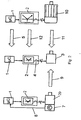
- Fig. 1 shows the circuit diagram of a conventional servo drive. It has a microcontroller 1 that is connected to an actuator 2. The signals from the actuator 2, which is power electronics, are fed to the motor 3. A current sensor 4 detects the current signals fed to the motor 3. The position of the rotor of the motor 3 is detected by a position encoder 7, the signals of which are fed to the microcontroller 1 via an encoder cable 8. The signals from the current sensor 4 are also fed to the microcontroller 1 via a line 28. The signals supplied via the cables 8, 28 are evaluated via an algorithm 5 of the microcontroller 1 and, if necessary, corresponding correction signals are supplied to the motor 3 via the actuator 2.
- the servo drive controls or regulates movements of machine axes.
- the movements of the machine axis are recorded with the position encoder 7. These movements can be rotary movements of the machine axis.
- Such machines are used, for example, for wire winding, wire straightening and the like.
- the machine axes can, however, also execute swiveling movements or shifting movements. Displacement movements occur, for example, with slides in packaging machines or with lifting mechanisms.
- the use of the encoder 7 is costly.
- the evaluation electronics 2 and the cabling in the form of the encoder cable 8 also lead to considerable costs.
- the position encoders 7 are very sensitive in use, and their reliability is limited depending on the application of the servo drive.
- the encoders 7 increase the overall volume of the servo drive.
- Fig. 2 shows two known servo drives in the right and left representation.
- a motor 29, which is provided with the position encoder 7, is driven by the left servo drive. Its signals are fed to the microcontroller 1 via the encoder cable 8 in the manner described, the signals of which are fed to the actuator 2.
- a synchronous reluctance machine 10 is operated on the right servo drive. It is connected to the actuator 2, which in turn is connected to the microcontroller 1.
- the actuator 2 which in turn is connected to the microcontroller 1.
- the microcontroller 1 For the synchronous reluctance machine 10 a relatively large power electronics 2 is required.
- the synchronous reluctance machine 10 itself also has a large volume.
- the middle representation in Fig. 2 shows the circuit diagram of a servo drive with a permanent magnet synchronous motor 3.
- the servo drive has the microcontroller 1, which is connected to the actuator 2 in the form of power electronics.
- the engine 3 is operated with it.
- the current sensor 4 detects the current supplied by the actuator 2 to the motor 3.
- the motor 3 is a permanent magnet synchronous motor.
- the servo drive according to the invention is characterized in that it has no encoder cable 8 and no encoder 7. This is indicated by the dashed arrow 9 in Fig. 2 marked.
- the motor 3 is a permanent magnet synchronous motor, it is much smaller than the synchronous reluctance machine 10 (arrow 11).
- the permanent magnet synchronous motor 3 also requires significantly smaller power electronics 2 (arrow 12).
- the servo drive is thus characterized by a compact design that is also inexpensive to purchase.
- a synchronous reluctance machine is described, of which the rotor 26 is shown.
- the corresponding induction curve over the angle ⁇ from 0 ° to 90 ° is shown in the corresponding diagram.
- the rotor 24 has four rotor arms 30 which extend from a central area and are connected to one another at the outer end by a ring 31.
- the arms 30 each have an angular distance of 90 ° from one another.
- the inductance-angle diagram shows that the inductance L is in the range of Rotor arms 30 (0 ° and 90 °) is largest and smallest in the area between them at 45 °.
- Fig. 4 shows the conditions in a permanent magnet synchronous motor, of which the rotor 6 is shown.
- the rotor 6 has the arms 30 which are arranged at angular intervals of 90 ° from one another and are connected to one another at the outer edge by the ring 31.
- the arms 30 are at an angle ⁇ of 45 °, 135 °, 225 °, 315 °.
- the inductance L has the lowest value in the area of the recesses 32 and the highest value in the area of the arms 30.
- the inductance curve 16 thus has the highest value at 45 ° and the lowest value at 0 ° and 90 °.
- a test frequency 18 is injected via the power electronics 2 in certain operating states ( Figures 5 and 6 ).
- the rotor position is determined via the measured current that then sets in. This position is used both for commutation and for speed and position control.
- the microcontroller 1 is able, without a position encoder, as it is used in the known servo drives, to operate a field-oriented control in all load and speed states only with the current measurement.
- the test signal 18 which is preferably in a frequency range of about 200 to 400 Hz, is in the case of Fig. 5 injected at a position angle ⁇ of -45 °, based on the angular position of the permanent magnets 13.
- the associated vector diagram shows the current Itest in the form of the current space vector 19.
- the angle ⁇ indicates that the actual position detected by means of the test signal 18 is 0 ° from the target position deviates by 0 °. Accordingly, in a manner to be described, the servo drive is readjusted in such a way that the actual position corresponds to the setpoint position.
- Fig. 6 it is shown by way of example that the test signal 18 is injected in the position 0 °.
- the associated vector diagram shows that the current space vector Itest lies in the 0 ° direction, ie that the measured actual position 0 ° corresponds to the target position 0 °.
- the error signal is thus 0.
- Fig. 8 the left figure shows an example of the inductance curve 20 of the rotor 17 of the permanent magnet synchronous motor.
- this permanent magnet synchronous motor is brought into saturation in a current-controlled manner, namely once against the rotor magnetic field 22 and once in the direction of the rotor magnetic field 23.
- these induction curves 22, 23 resulting from the saturation current supply are shown by way of example.
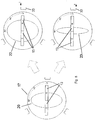
- Fig. 9 In the left figure shows the rotor 17 with the inductance curve 20, which results when the motor is not energized. If it is energized, then the inductance curve 21 changes, like the illustration on the right in FIG Fig. 9 shows. The difference between the two induction curves 20 is denoted by ⁇ .
- the geometric inductance curve of the permanent magnet synchronous motor is dependent on the current supply to the motor, in particular when the rotor 17 is saturated.
- the position error can be described as a displacement about the axis of rotation of the rotor 17.
- the permanent magnet synchronous motor is measured beforehand and a table is determined which describes this shift ⁇ . This table is stored in microcontroller 1. When compensating for the position error ⁇ caused by saturation, this table is used, which is determined separately for each permanent magnet synchronous motor and stored in the microcontroller.
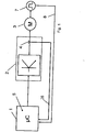
- a device 24 is provided. With it, the stator field is tracked to the rotating rotor 17 in order to eliminate the shift ⁇ .
- the test signal 18 is injected in the manner described and the position of the current space pointer 19 is determined using the measured current that is established. It is taken into account in the described saturation current flow.
- the device 24 sends out a signal ⁇ *, which results from the injected test signal 18 and indicates the current position of the rotor 17.
- This signal characterizes the described position error ⁇ , which is compensated for by a corresponding saturation current supply.
- the comparison values stored in table form in the microcontroller are used here.
- the position error ⁇ is canceled by the saturation compensation, which is shown in the figure below Fig. 9 is marked with ⁇ .
- the position compensation is advantageously carried out by means of a control.
- the rotor 17 has a special design that is based on Fig. 10 is described in more detail. This design is chosen with a view to the fact that the inductance-angle curve ( Figs. 3 and 4 ) approaches a straight line. Then it is difficult to regulate the motor.
- the design of the rotor 17 described below ensures that, even with the high currents, a curve of the inductance 16 results, as shown in FIG Figs. 3 and 4 is shown.
- the rotor design results in a high degree of efficiency.
- the reluctance torque is used to the maximum, which contributes to an optimal torque.
- the rotor 17 is formed by a laminated core 14, which consists of sheet metal lamellas lying on top of one another, which are firmly connected to one another in a suitable manner.
- the laminated core 14 has recesses 34 distributed over the circumference, which extend over the height of the laminated core 14 and are advantageously designed in the same way.
- the recesses 34 accommodate the permanent magnets 13.
- six recesses 34 and accordingly six permanent magnet stacks 13 are arranged evenly distributed over the circumference of the rotor 17, which are arranged in the manner of secants.
- the individual permanent magnets 13 are each formed identically and preferably have a rectangular shape.
- the permanent magnets 13 rest with their end faces against one another and with their long sides on the side walls of the recess 34.
- the permanent magnets 13 within the recess 34 are permanent magnets of the same type, with homopolar permanent magnets 13 being arranged within the recess 34.
- the poles of the permanent magnets 13 alternate over the circumference of the laminated core 14.
- Recesses 15 serving as flow barriers adjoin the end faces 35, 36 of the recesses 34. They are arranged in the laminated core 14 in such a way that they minimize the rotor losses and in this way contribute to a very high efficiency of the rotor 17.
- the recesses 15 extend from the end faces 35, 36 in the direction of the outer edge 37 of the laminated core 14 and end at a small distance from the edge 37 a small distance from the end faces 35, 36 of the recesses 34 extend over those adjacent to the jacket 37 of the laminated core 14
- the longitudinal side of the recesses 34 extend and end at a small distance from the laminated core jacket 37.
- the laminated core 14 is provided in the area between adjacent recesses 34 with a respective groove 38 which extends over the height of the laminated core 14.
- the grooves 38 are formed identically and open into the outer jacket of the laminated core 14. Their width steadily decreases radially inward.
- the side walls 39, 40 of the grooves 38 preferably merge into one another in an arc shape.
- the grooves 38 thus have a V-shape as seen in the axial direction of the laminated core 14.
- the grooves 38 each lie between two cutouts 15 of adjacent cutouts 34.
- the grooves 38 are advantageously used to reinforce the magnetic anisotropy of the laminated core 14.
- the laminated core 14 has a central opening 41 into which a rotor shaft (not shown) protrudes.
- a rotor shaft (not shown) protrudes.
- two form-fit elements 42 are provided, for example, into which corresponding counter-form-fit elements of the rotor shaft engage and thus produce a simple and reliable non-rotatable connection between the rotor 17 and the rotor shaft.
- the laminated core is provided with further recesses 43 which are arranged and designed in such a way that they do not impair the magnetic flux and lead to a considerable saving in weight.
- the lamellae which, when placed one on top of the other, form the laminated core 14 are designed in one piece. It is possible to produce the laminated core 14 also from individual partial laminated cores, which in turn are formed from partial lamellas. These partial laminated stacks are joined together in a known manner to form a complete laminated stacks 14.
- the full torque can be achieved in all operating states when the permanent magnet synchronous motor is in operation.
- the drive can be reliably positioned even under load.
- the servo drive enables a very high power density that is greater than the power density of synchronous reluctance machines or synchronous servomotors with position encoders.
- the permanent magnet synchronous motor requires less power than synchronous reluctance machines. This means that a smaller size can be used for the drive controller. Since the position encoder and the encoder cable are no longer necessary, the costs for the servo drive can be reduced considerably.
- the energy efficiency of the servo drive corresponds to the energy efficiency of synchronous servomotors with position encoders.
- the dynamic properties of the servo drive are better than other servo drives without a position encoder. The power requirement of the servo drive is also low.
Landscapes
- Engineering & Computer Science (AREA)
- Power Engineering (AREA)
- Control Of Ac Motors In General (AREA)
- Control Of Motors That Do Not Use Commutators (AREA)
Description
- Die Erfindung bezieht sich auf ein Verfahren zur Bestimmung der Position eines Rotors eines Permanentmagnetservomotors nach dem Oberbegriff des Anspruches 1.
- Ein solches Verfahren ist aus
US 6 051 946 A bekannt. - Es ist weiter bekannt (
US 2014/327379 A1 ), eine Sättigung des Rotors einmal gegen und einmal in Richtung des Rotormagnetfeldes vorzunehmen. AusDE 10 2007 057 499 A1 ist es bekannt, die Drehposition eines Rotors unter Verwendung von Informationen zu erfassen, die in Datentabellen gespeichert sind. - Um die Position eines Rotors eines Elektromotors zu bestimmen, werden Positions-Encoder eingesetzt. Sie werden mittels eines Encoder-Kabels an einen Mikrocontroller angeschlossen. Die Positions-Encoder sind teure Bauteile, die den entsprechenden Antrieb verteuern. Die Auswerteelektronik solcher Encoder sowie die Verkabelung sind darüber hinaus im Einsatz empfindlich und störanfällig.
- Der Erfindung liegt die Aufgabe zugrunde, das gattungsgemäße Verfahren so auszubilden, dass bei kostengünstiger Ausbildung eine zuverlässige Lagebestimmung des Rotors erreicht wird.
- Diese Aufgabe wird beim gattungsgemäßen Verfahren erfindungsgemäß mit den kennzeichnenden Merkmalen des Anspruches 1 gelöst.
- Der Servoantrieb zeichnet sich dadurch aus, dass für die Lagebestimmung des Rotors ein Positions-Encoder nicht mehr erforderlich ist. Es wird in bestimmten Betriebszuständen das Strom-Testsignal injiziert. Über den sich dann einstellenden gemessenen Strom kann die Rotorposition einfach und dennoch genau bestimmt werden. Die Rotorposition kann sowohl für die Kommutierung als auch für eine Geschwindigkeits- und Positionsregelung verwendet werden.
- Vorteilhaft wird das Strom-Testsignal über das Stellglied zugeführt, das bevorzugt eine Leistungselektronik des Servoantriebes ist.
- Der Motor ist ein Permanentmagnetsynchronmotor.
- Beim Servoantrieb wird anhand des dem nach dem Injizieren des Testsignales sich ergebenden Stromes zugehörigen Zeigerdiagramms der Stromraumzeiger ermittelt. Anhand der Winkellage des Stromraumzeigers kann die Position des Rotors einwandfrei festgestellt werden. Tritt ein Positionsfehler auf, wird das Statorfeld dem sich drehenden Rotor nachgeführt.
- Beim erfindungsgemäßen Verfahren erfolgt eine Korrektur des sättigungsbedingten Positionsfehlers. Beim Permanentmagnetsynchronmotor wird die Nord-Süd-Richtung berücksichtigt. Infolge der Permanentmagnete hat der Rotor einen charakteristischen Verlauf der Induktivität. Der Motor wird zunächst stromgeregelt in Sättigung gebracht. Der (Dem) sich ergebenden Spannung bzw. Strom wird ein definierter Strom/Spannungsverlauf überlagert. Dies führt zu einer Änderung der Induktivität, woraus die aktuelle Ausrichtung des Rotors ermittelt werden kann. Beim erfindungsgemäßen Verfahren wird der Sättigungseffekt ausgenutzt, um eine vorhandene Nord-Süd-Redundanz des Permanentmagnetsynchronmotors zu eliminieren. Der geometrische Verlauf der Induktivität beim Permanentmagnetsynchronmotor ist abhängig von der Bestromung des Motors, insbesondere bei Sättigung des Rotors. Die Sättigung kann als Verschiebung um die Rotationsachse des Rotors beschrieben werden.
- Der geometrische Verlauf der Induktivität bei Bestromung des Motors wird erfasst und mit gespeicherten Werten verglichen. Der Permanentmagnetsynchronmotor wird vorher ausgemessen und die mögliche Verschiebung der Position des Rotors festgehalten. Anhand dieser gespeicherten Werte kann dann eine gemessene Verschiebung der Rotorposition sehr einfach kompensiert werden.
- Ein Positionsfehler des Rotors, der durch Bestromen des Rotors hervorgerufen wird, wird in der Folge kompensiert.
- Die gespeicherten Werte enthalten die Positionsfehler des Rotors und die zur Kompensation dieses Positionsfehlers erforderlichen Stromwerte, vorzugsweise in Tabellenform. Dadurch kann die Kompensation des Positionsfehlers sehr einfach und genau durchgeführt werden.
- Der Rotor wird einmal gegen und einmal in Richtung des Rotormagnetfeldes stromgeregelt in Sättigung gebracht. Mit einer solchen Vorgehensweise kann die Nord-Süd-Redundanz sicher eliminiert werden.
- Eine exakte und einfache Bestimmung des Positionsfehlers ergibt sich, wenn er als Verschiebung der Position um die Drehachse des Rotors bestimmt wird.
- Der Rotor ist so ausgeformt, dass sowohl Reluktanzmomente als auch aus dem EMK-Prinzip herrührende Momente ermöglicht werden. Die Flusssperren minimieren die Rotorverluste und erhöhen den Wirkungsgrad. Erreicht wird dies dadurch, dass die Flusssperren an die Aussparungen für die Permanentmagnete anschließen. Die Flusssperren sind Ausstanzungen in den einzelnen Lamellen des Blechpaketes.
- Vorteilhaft münden die Flusssperren in die Aussparungen für die Permanentmagnete. Diese Ausbildung ermöglicht auch ein einfaches Stanzen der Lamellen.
- Die Aussparungen haben bei einer einfachen Ausführungsform vorteilhaft rechteckigen Umriss.
- Bevorzugt schließen die Flusssperren an die Stirnseiten der rechteckigen Aussparungen an.
- Ein Flussverlust wird zuverlässig in vorteilhafter Form dann verhindert, wenn sich die Flusssperren in Richtung auf den äußeren Mantel des Blechpaketes erstrecken.
- Um die Anisotropie des Blechpaketes zu verstärken, weist das Blechpaket in vorteilhafter Ausbildung randseitige Nuten auf, die im Bereich zwischen benachbarten Aussparungen liegen.
- Diese Nuten erstrecken sich vorteilhaft bis zwischen die Flusssperren benachbarter Aussparungen. Dadurch wirken die Nuten mit den Flusssperren so zusammen, dass Flussverluste sicher verhindert werden und die Feldlinien im Einsatz des Rotors zuverlässig durch den Luftspalt zwischen dem Rotor und dem Stator verlaufen.
- Vorteilhaft verjüngen sich die Nuten vom äußeren Mantel des Blechpaketes aus nach innen.
- Die Erfindung wird anhand eines in den Zeichnungen dargestellten Ausführungsbeispieles näher erläutert. Es zeigen
- Fig. 1
- in einem Schaltbild einen Servoantrieb nach dem Stand der Technik,
- Fig. 2
- ein Schaltbild eines Servoantriebes ohne Encoder,
- Fig. 3
- in schematischer Darstellung den Rotor einer Synchron-Reluktanzmaschine und der zugehörige anisotropische Induktivi-tätsverlauf,
- Fig. 4
- in einer Darstellung entsprechend
Fig. 3 den Rotor eines Permanentmagnetsynchronmotors und zugehörigem anisotropischen Induktivitätsverlauf, - Fig. 5 und Fig. 6
- in schematischer Darstellung den Rotor eines Permanentmagnetsynchronmotors mit Statorspulen, dem ein Testsignal zugeführt wird sowie den hieraus sich ergebenden Stromraumzeiger,
- Fig. 7
- in einem Schaltbild eine Einrichtung zur Nachführung des Statorfeldes an die Rotorlage,
- Fig. 8
- in schematischer Darstellung die Vorgehensweise bei einer Eliminierung einer Nord-Süd-Redundanz eines Permanentmagnetsynchronmotors,
- Fig. 9
- in schematischer Darstellung die Korrektur eines sättigungsbedingten Positionsfehlers bei einem Permanentmagnetsynchronmotor,
- Fig. 10
- einen Schnitt durch einen Rotor eines Permanentmagnetsynchronmotors.
-
Fig. 1 zeigt das Schaltbild eines herkömmlichen Servoantriebes. Er hat einen Mikrocontroller 1, der an ein Stellglied 2 angeschlossen ist. Die Signale des Stellgliedes 2, das eine Leistungselektronik ist, werden dem Motor 3 zugeführt. Ein Stromsensor 4 erfasst die dem Motor 3 zugeführten Stromsignale. Die Position des Rotors des Motors 3 wird durch einen Positionsencoder 7 erfasst, dessen Signale über ein Encoderkabel 8 dem Mikrocontroller 1 zugeführt werden. Auch die Signale des Stromsensors 4 werden über eine Leitung 28 dem Mikrocontroller 1 zugeführt. Über einen Algorithmus 5 des Mikrocontrollers 1 werden die über die Kabel 8, 28 zugeführten Signale ausgewertet und bei Bedarf entsprechende Korrektursignale über das Stellglied 2 dem Motor 3 zugeführt. - Mit dem Servoantrieb werden Bewegungen von Maschinenachsen gesteuert bzw. geregelt. Mit dem Positionsencoder 7 werden die Bewegungen der Maschinenachse erfasst. Diese Bewegungen können Drehbewegungen der Maschinenachse sein. Solche Maschinen werden beispielsweise zum Drahtwickeln, Drahtrichten und dergleichen eingesetzt. Die Maschinenachsen können aber auch Schwenkbewegungen oder Verschiebebewegungen ausführen. Verschiebebewegungen treten beispielsweise bei Schiebern in Verpackungsmaschinen oder bei Hubwerken auf.
- Die Verwendung der Encoder 7 ist kostenaufwändig. Auch die Auswerteelektronik 2 und die Verkabelung in Form des Encoderkabels 8 führt zu erheblichen Kosten. Die Positionsencoder 7 sind im Einsatz sehr empfindlich, und ihre Zuverlässigkeit ist je nach Einsatzfall des Servoantriebes eingeschränkt. Darüber hinaus erhöhen die Encoder 7 das Bauvolumen des Servoantriebes.
-
Fig. 2 zeigt in der rechten und linken Darstellung zwei bekannte Servoantriebe. Mit dem linken Servoantrieb wird ein Motor 29 angetrieben, der mit dem Positionsencoder 7 versehen ist. Seine Signale werden über das Encoderkabel 8 in der beschriebenen Weise dem Mikrocontroller 1 zugeführt, dessen Signale dem Stellglied 2 zugeführt werden. - Mit dem in
Fig. 2 rechten Servoantrieb wird eine Synchron-Reluktanzmaschine 10 betrieben. Sie ist an das Stellglied 2 angeschlossen, das seinerseits mit dem Mikrocontroller 1 verbunden ist. Für die Synchron-Reluktanzmaschine 10 ist eine verhältnismäßig große Leistungselektronik 2 erforderlich. Auch die Synchron-Reluktanzmaschine 10 selbst hat ein großes Volumen. - Die mittlere Darstellung in
Fig. 2 zeigt das Schaltbild eines Servoantriebes mit einem Permanentmagnetsynchronmotor 3. Der Servoantrieb hat den Mikrocontroller 1, der an das Stellglied 2 in Form der Leistungselektronik angeschlossen ist. Mit ihr wird der Motor 3 betrieben. Der Stromsensor 4 erfasst den vom Stellglied 2 an den Motor 3 gelieferten Strom. Im Ausführungsbeispiel ist der Motor 3 ein Permanentmagnetsynchronmotor. - Ein Vergleich dieses mittleren Servoantriebes mit den beiden bekannten Servoantrieben zeigt Folgendes. Im Vergleich zum Servoantrieb gemäß der linken Abbildung zeichnet sich der erfindungsgemäße Servoantrieb dadurch aus, dass er kein Encoderkabel 8 und keinen Encoder 7 aufweist. Dies ist durch den gestrichelten Pfeil 9 in
Fig. 2 kenntlich gemacht. - Im Vergleich zu dem in
Fig. 2 rechten Servoantrieb ist beim mittleren Servoantrieb ein Algorithmus im Mikrocontroller 1 nicht erforderlich, was durch den gestrichelten Pfeil 5 angedeutet ist. Da der Motor 3 ein Permanentmagnetsynchronmotor ist, baut er wesentlich kleiner als die Synchron-Reluktanzmaschine 10 (Pfeil 11). Der Permanentmagnetsynchronmotor 3 benötigt darüber hinaus eine wesentlich kleinere Leistungselektronik 2 (Pfeil 12). Somit zeichnet sich der Servoantrieb durch eine kompakte Ausbildung aus, die zudem kostengünstig in der Anschaffung ist. - Anhand von
Fig. 3 wird eine Synchron-Reluktanzmaschine beschrieben, von der der Rotor 26 dargestellt ist. Der zugehörige Induktionsverlauf über den Winkel ϕ von 0° bis 90° ist im entsprechenden Diagramm dargestellt. Der Rotor 24 hat vier Rotorarme 30, die von einem zentralen Bereich ausgehen und am äußeren Ende durch einen Ring 31 miteinander verbunden sind. Die Arme 30 haben jeweils einen Winkelabstand von 90° voneinander. Das Induktivitäts-Winkel-Diagramm zeigt, dass die Induktivität L im Bereich der Rotorarme 30 (0° und 90°) am größten und im Bereich zwischen ihnen bei 45° am geringsten ist. -
Fig. 4 zeigt die Verhältnisse bei einem Permanentmagnetsynchronmotor, von dem der Rotor 6 dargestellt ist. Der Rotor 6 hat die Arme 30, die in Winkelabständen von 90° zueinander angeordnet und am äußeren Rand durch den Ring 31 miteinander verbunden sind. Die Arme 30 liegen im dargestellten Ausführungsbeispiel bei einem Winkel ϕ von 45°, 135°, 225°, 315°. - Zwischen den Armen 30 befinden sich Aussparungen 30, in denen Permanentmagnete 13 angeordnet sind. Beispielhaft sind in jeder Aussparung 32 drei nebeneinander liegende Permanentmagnete 13 angeordnet. Sie sind jeweils in einer Reihe nebeneinander angeordnet, wobei Nord- und Südpole in bekannter Weise abwechselnd vorgesehen sind. Wie das zugehörige Induktivitäts-Winkel-Diagramm zeigt, hat die Induktivität L im Bereich der Aussparungen 32 den geringsten und im Bereich der Arme 30 den höchsten Wert. Im Ausführungsbeispiel, bei dem der Winkelbereich von 0° bis 90° betrachtet wird, hat die Induktivitätskurve 16 somit bei 45° den höchsten und bei 0° und 90° den geringsten Wert.
- Um die Rotorposition des Motors zu bestimmen, wird in bestimmten Betriebszuständen über die Leistungselektronik 2 eine Testfrequenz 18 injiziert (
Fig. 5 und 6 ). Über den sich dann einstellenden gemessenen Strom wird die Rotorposition bestimmt. Diese Position wird sowohl für die Kommutierung als auch für die Geschwindigkeits- und Positionsregelung verwendet. Der Mikrocontroller 1 ist in der Lage, ohne einen Positionsencoder, wie er bei den bekannten Servoantrieben eingesetzt wird, nur mit der Strommessung eine feldorientierte Regelung in allen Last- und Drehzahlzuständen zu betreiben. - Anhand der
Fig. 5 und 6 werden unterschiedliche Ausrichtungen des Statorfeldes zum Rotor 17 beispielhaft beschrieben. Das Testsignal 18, das bevorzugt in einem Frequenzbereich von etwa 200 bis 400 Hz liegt, wird im Falle derFig. 5 bei einem Positionswinkel ϕ von -45° injiziert, bezogen auf die Winkellage der Permanentmagnete 13. Das zugehörige Zeigerdiagramm zeigt den Strom Itest in Form des Stromraumzeigers 19. Der Winkel α zeigt an, dass die mittels des Testsignales 18 erfasste Ist-Position 0° von der Soll-Position 0° abweicht. Dementsprechend wird in noch zu beschreibender Weise der Servoantrieb so nachgeregelt, dass die Ist-Position der Soll-Position entspricht. - In
Fig. 6 ist beispielhaft dargestellt, dass das Testsignal 18 in der Position 0° injiziert wird. Das zugehörige Zeigerdiagramm zeigt, dass der Stromraumzeiger Itest in 0°-Richtung liegt, d. h., dass die gemessene Ist-Position 0° der Soll-Position 0° entspricht. Das Fehlersignal ist somit 0. - Tritt, wie anhand von
Fig. 5 beispielhaft beschrieben, das Fehlersignal auf, dann muss mit Hilfe des Motorstroms eine Positionskorrektur vorgenommen werden, damit die Ist-Position mit der Soll-Position übereinstimmt. - Bei einem Permanentmagnetsynchronmotor kommt es darauf an, dass die Nord-Süd-Richtung bei der Messung berücksichtigt wird. Ausgangspunkt ist, wie anhand der
Fig. 5 und 6 beschrieben, der Rotor 17, der infolge der Permanentmagnete 13 einen charakteristischen Induktivitätsverlauf 20 aufweist (Fig. 8 ). - In
Fig. 8 ist in der linken Abbildung beispielhaft der Induktivitätsverlauf 20 des Rotors 17 des Permanentmagnetsynchronmotors dargestellt. In einem ersten Schritt wird dieser Permanentmagnetsynchronmotor stromgeregelt in die Sättigung gebracht, und zwar einmal gegen das Rotormagnetfeld 22 und einmal in Richtung des Rotormagnetfeldes 23. Diese unterschiedliche Stromzuführung an den Statorspulen 33 ist durch den entsprechenden Pfeil I gekennzeichnet. In der rechten Darstellung derFig. 8 sind diese bei der Sättigungsbestromung sich ergebenden Induktionsverläufe 22, 23 beispielhaft dargestellt. - In einem zweiten Schritt wird der sich ergebenden Spannung jeweils ein definierter Spannungsverlauf überlagert, wie anhand von
Fig. 5 und 6 erläutert worden ist. Aus dem gemessenen Strom kann hierbei die Veränderung der Induktivität L und damit die aktuelle Ausrichtung des Rotors 17 ermittelt werden. - Anhand von
Fig. 9 wird beschrieben, wie eine Nord-Süd-Redundanz des Rotors 17 des Permanentmagnetsynchronmotors durch entsprechende Korrektur eliminiert werden kann.Fig. 9 zeigt in der linken Abbildung den Rotor 17 mit dem Induktivitätsverlauf 20, der sich ergibt, wenn der Motor nicht bestromt ist. Wird er bestromt, dann verändert sich der Induktivitätsverlauf 21, wie die rechte Darstellung derFig. 9 zeigt. Der Unterschied zwischen den beiden Induktionsverläufen 20 ist mit Δϕ bezeichnet. Der geometrische Induktivitätsverlauf des Permanentmagnetsynchronmotors ist abhängig von der Bestromung des Motors, insbesondere bei Sättigung des Rotors 17. Der Positionsfehler lässt sich als Verschiebung um die Rotationsachse des Rotors 17 beschreiben. - Der Permanentmagnetsynchronmotor wird vorher ausgemessen und hierbei eine Tabelle ermittelt, die diese Verschiebung Δϕ beschreibt. Diese Tabelle wird im Mikrocontroller 1 abgelegt. Bei der Kompensation des sättigungsbedingten Positionsfehlers Δϕ wird auf diese Tabelle zurückgegriffen, die für jeden Permanentmagnetsynchronmotor gesondert ermittelt und im Mikrocontroller gespeichert.
- Um diese Korrektur des sättigungsbedingten Positionsfehlers Δϕ durchführen zu können, ist eine Einrichtung 24 vorgesehen. Mit ihr wird das Statorfeld dem sich drehenden Rotor 17 nachgeführt, um die Verschiebung Δϕ zu beseitigen. Hierzu wird das Testsignal 18 in der beschriebenen Weise injiziert und über den sich einstellenden gemessenen Strom die Lage des Stromraumzeigers 19 ermittelt. Er wird bei der beschriebenen Sättigungsbestromung berücksichtigt. Die Einrichtung 24 sendet ein Signal ϕ* aus, das sich aufgrund des injizierten Testsignales 18 ergibt und die augenblickliche Position des Rotors 17 anzeigt. Dieses Signal kennzeichnet den beschriebenen Positionsfehler Δϕ, der durch entsprechende Sättigungsbestromung ausgeglichen wird. Hierbei werden die in Tabellenform im Mikrocontoller abgespeicherten Vergleichswerte herangezogen. Durch die Sättigungskompensation wird der Positionsfehler Δϕ aufgehoben, was in der unteren Abbildung der
Fig. 9 mit ϕ gekennzeichnet ist. Vorteilhaft erfolgt die Positionskompensation mittels einer Regelung. - Damit der Permanentmagnetsynchronmotor zuverlässig geregelt werden kann, hat der Rotor 17 eine besondere Gestaltung, die anhand von
Fig. 10 näher beschrieben wird. Diese Gestaltung ist im Hinblick darauf gewählt, dass sich bei einem hohen Strom die Induktivitäts-Winkel-Kurve (Fig. 3 und 4 ) einer Geraden nähert. Dann ist eine Regelung des Motors nur schwierig zu erreichen. Die nachfolgend beschriebene Gestaltung des Rotors 17 stellt sicher, dass auch bei den hohen Strömen sich ein Kurvenverlauf der Induktivität 16 ergibt, wie er in denFig. 3 und 4 dargestellt ist. - Durch die Rotorgestaltung ergibt sich ein hoher Wirkungsgrad. Außerdem erfolgt eine maximale Ausnutzung des Reluktanzmomentes, was zu einem optimalen Drehmoment beiträgt.
- Der Rotor 17 wird durch ein Blechpaket 14 gebildet, das aus aufeinander liegenden Blechlamellen besteht, die in geeigneter Weise fest miteinander verbunden sind. Das Blechpaket 14 hat über den Umfang verteilt Aussparungen 34, die sich über die Höhe des Blechpaketes 14 erstrecken und vorteilhaft gleich ausgebildet sind. Die Aussparungen 34 nehmen die Permanentmagnete 13 auf. In jeder Aussparung 34 befinden sich drei nebeneinander liegende Permanentmagnete 13. Im Ausführungsbeispiel sind über den Umfang des Rotors 17 gleichmäßig verteilt sechs Aussparungen 34 und dementsprechend sechs Permanentmagnetpakete 13 angeordnet, die nach Art von Sekanten angeordnet sind. Die einzelnen Permanentmagnete 13 sind jeweils gleich ausgebildet und haben vorzugsweise Rechteckform. Innerhalb der Aussparung 34 liegen die Permanentmagnete 13 mit ihren Stirnseiten aneinander und mit ihren Längsseiten an den Seitenwänden der Aussparung 34. Die Permanentmagnete 13 innerhalb der Aussparung 34 sind gleichartige Permanentmagnete, wobei innerhalb der Aussparung 34 gleichpolige Permanentmagnete 13 angeordnet sind. Über den Umfang des Blechpaketes 14 wechseln die Pole der Permanentmagnete 13 ab.
- An die Stirnseiten 35, 36 der Aussparungen 34 schließen als Flusssperren dienende Aussparungen 15 an. Sie sind so im Blechpaket 14 angeordnet, dass sie die Rotorverluste minimieren und auf diese Weise zu einem sehr hohen Wirkungsgrad des Rotors 17 beitragen.
- Die Aussparungen 15 erstrecken sich von den Stirnseiten 35, 36 aus in Richtung auf den äußeren Rand 37 des Blechpaketes 14 und enden mit geringem Abstand vom Rand 37. Die Aussparungen 15 sind wesentlich kleiner als die Aussparungen 34 und haben gerade Außenränder 44, die sich mit geringem Abstand zu den Stirnseiten 35, 36 der Aussparungen 34 erstrecken, sich über die dem Mantel 37 des Blechpaketes 14 benachbarte Längsseite der Aussparungen 34 erstrecken und mit geringem Abstand vom Blechpaketmantel 37 enden.
- Das Blechpaket 14 ist im Bereich zwischen benachbarten Aussparungen 34 mit jeweils einer Nut 38 versehen, die sich über die Höhe des Blechpaketes 14 erstreckt. Die Nuten 38 sind gleich ausgebildet und münden in den äußeren Mantel des Blechpaketes 14. Radial nach innen nimmt ihre Breite stetig ab. Die Seitenwände 39, 40 der Nuten 38 gehen vorzugsweise bogenförmig ineinander über. Die Nuten 38 haben somit, in Achsrichtung des Blechpaketes 14 gesehen, V-Form. Die Nuten 38 liegen jeweils zwischen zwei Aussparungen 15 benachbarter Aussparungen 34.
- Die Nuten 38 dienen vorteilhaft zur Verstärkung der magnetischen Anisotropie des Blechpaketes 14.
- Das Blechpaket 14 hat eine zentrale Öffnung 41, in die eine (nicht dargestellte) Rotorwelle ragt. Am Umfang der Öffnung 41 sind beispielhaft zwei Formschlusselemente 42 vorgesehen, in die entsprechende Gegenformschlusselemente der Rotorwelle eingreifen und so eine einfache und zuverlässige drehfeste Verbindung zwischen dem Rotor 17 und der Rotorwelle herstellen.
- Im Bereich zwischen der Öffnung 41 und den Aussparungen 34 ist das Blechpaket mit weiteren Aussparungen 43 versehen, die so angeordnet und ausgebildet sind, dass sie den Magnetfluss nicht beeinträchtigen und zu einer erheblichen Gewichtsersparnis führen.
- Im Ausführungsbeispiel sind die Lamellen, die aufeinandergesetzt das Blechpaket 14 bilden, einstückig ausgebildet. Es ist möglich, das Blechpaket 14 auch aus einzelnen Teilblechpaketen herzustellen, die ihrerseits aus Teillamellen gebildet sind. Diese Teilblechpakete werden in bekannter Weise miteinander zum kompletten Blechpaket 14 zusammengefügt.
- Mit einer solchen Ausbildung des Blechpaketes 14 kann im Betrieb des Permanentmagnetsynchronmotors das volle Drehmoment in allen Betriebszuständen erreicht werden. Darüber hinaus kann der Antrieb auch unter Last zuverlässig positioniert werden.
- Der Servoantrieb ermöglicht eine sehr hohe Leistungsdichte, die größer ist als die Leistungsdichte von Synchron-Reluktanzmaschinen oder Synchron-Servomotoren mit Positionsencodern. Für den Permanentmagnetsynchronmotor ist weniger Strombedarf erforderlich als für Synchron-Reluktanzmaschinen. Dadurch kann für den Antriebsregler eine kleinere Baugröße herangezogen werden. Da der Positionsencoder und das Encoderkabel wegfallen, können die Kosten für den Servoantrieb erheblich gesenkt werden. Die Energieeffizienz des Servoantriebes entspricht der Energieeffizienz von Synchron-Servomotoren mit Positions-Encoder. Die dynamischen Eigenschaften des Servoantriebes sind besser als andere Servoantriebe ohne Positions-Encoder. Der Strombedarf des Servoantriebes ist zudem gering.
Claims (3)
- Verfahren zur Bestimmung der Position eines Rotors (6, 17, 26) eines Permanentmagnetsynchronmotors bei einem Servoantrieb, bei dem zur Bestimmung der Rotorposition eine feldorientierte Regelung vorgesehen ist, bei der ein Strom-Testsignal (18) injiziert und aus dem sich ergebenden Strom die Rotorposition bestimmt wird, wobei der Permanentmagnetsynchronmotor in Sättigung gebracht wird, anschließend ein definierter Spannung/Stromverlauf der (dem) sich ergebenden Spannung/Strom überlagert wird, die hieraus sich ergebende Änderung der Induktivität (L) erfasst und daraus die Position des Rotors (17) ermittelt wird, wobei der Verlauf (20 bis 23) der Induktivität als Funktion der Rotorlage bei Bestromung des Rotors (17) erfasst und mit gespeicherten Werten verglichen wird, wobei die gespeicherten Werte die Positionsfehler (Δϕ) des Rotors (17) und die zur Kompensation dieses Positionsfehlers erforderlichen Stromwerte enthalten, vorzugsweise in Tabellenform, und zur Korrektur des sättigungsbedingten Positionsfehlers (Δϕ) eine Einrichtung (24) vorgesehen ist, wobei mittels des injizierten Testsignals (8) über den sich einstellenden gemessenen Strom die Lage eines Stromzeigers (19) ermittelt wird, der bei der Sättigungsbestromung berücksichtigt wird, wobei die Einrichtung (24) ein Signal (ϕ*) aussendet, das sich aufgrund des Testsignals (18) ergibt und die augenblickliche Position des Rotors (17) anzeigt sowie den Positionsfehler (Δϕ) kennzeichnet, und die das Statorfeld dem drehenden Rotor (17) nachführt, um den Positionsfehler (Δϕ) zu kompensieren,
dadurch gekennzeichnet, dass der Permanentmagnetsynchronmotor stromgeregelt ist, wenn er in Sättigung gebracht wird, und dass der Rotor (17) einmal gegen und einmal in Richtung des Rotormagnetfeldes stromgeregelt in Sättigung gebracht wird. - Verfahren nach Anspruch 1,
dadurch gekennzeichnet, dass der Positionsfehler (Δϕ) als Verschiebung der Position um die Drehachse des Rotors (17) bestimmt wird. - Verfahren nach Anspruch 1 oder 2,
dadurch gekennzeichnet, dass das Strom-Testsignal (18) über ein Stellglied (2) zugeführt wird, das vorzugsweise eine Leistungselektronik ist.
Applications Claiming Priority (1)
| Application Number | Priority Date | Filing Date | Title |
|---|---|---|---|
| DE102015005478.3A DE102015005478A1 (de) | 2015-04-28 | 2015-04-28 | Servoantrieb, Verfahren zur Bestimmung der Position eines Rotors eines Permanentmagnetservomotors sowie Rotor zur Verwendung beim Servoantrieb und beim Verfahren |
Publications (3)
| Publication Number | Publication Date |
|---|---|
| EP3089351A2 EP3089351A2 (de) | 2016-11-02 |
| EP3089351A3 EP3089351A3 (de) | 2017-02-22 |
| EP3089351B1 true EP3089351B1 (de) | 2021-11-10 |
Family
ID=55808926
Family Applications (1)
| Application Number | Title | Priority Date | Filing Date |
|---|---|---|---|
| EP16000903.1A Revoked EP3089351B1 (de) | 2015-04-28 | 2016-04-21 | Verfahren zur bestimmung der position eines rotors eines permanentmagnetservomotors |
Country Status (2)
| Country | Link |
|---|---|
| EP (1) | EP3089351B1 (de) |
| DE (1) | DE102015005478A1 (de) |
Families Citing this family (2)
| Publication number | Priority date | Publication date | Assignee | Title |
|---|---|---|---|---|
| DE102019214051B4 (de) * | 2019-09-16 | 2021-07-15 | Zf Friedrichshafen Ag | Trommelantrieb einer Mischtrommel eines Fahrmischers |
| CN116362148B (zh) * | 2023-02-27 | 2023-09-05 | 湖南大学 | 一种高速永磁电机转子涡流损耗计算方法 |
Citations (5)
| Publication number | Priority date | Publication date | Assignee | Title |
|---|---|---|---|---|
| US6051946A (en) | 1997-09-12 | 2000-04-18 | Toyota Jidosha Kabushiki Kaisha | Electrical angle detection apparatus, method of detecting electrical angle, and motor control apparatus |
| EP1526635A2 (de) | 2003-10-22 | 2005-04-27 | Fanuc Ltd | Detektionseinrichtung, und -verfahren zur Detektion der Position von Magnet-Polen |
| DE102007057499A1 (de) | 2006-11-30 | 2008-06-05 | Denso Corp., Kariya | System und Verfahren zum Steuern eines Motors unter Verwendung eines mit einem magnetischen Fluss zusammenhängenden Parameters |
| US20100171455A1 (en) | 2009-01-05 | 2010-07-08 | Gm Global Technology Operations, Inc. | Initial polarity detection for permanent magnet motor drives |
| US20140327379A1 (en) | 2013-05-03 | 2014-11-06 | Texas Instruments Incorporated | Position sensorless drive system and method for permanent magnet motors |
-
2015
- 2015-04-28 DE DE102015005478.3A patent/DE102015005478A1/de not_active Withdrawn
-
2016
- 2016-04-21 EP EP16000903.1A patent/EP3089351B1/de not_active Revoked
Patent Citations (5)
| Publication number | Priority date | Publication date | Assignee | Title |
|---|---|---|---|---|
| US6051946A (en) | 1997-09-12 | 2000-04-18 | Toyota Jidosha Kabushiki Kaisha | Electrical angle detection apparatus, method of detecting electrical angle, and motor control apparatus |
| EP1526635A2 (de) | 2003-10-22 | 2005-04-27 | Fanuc Ltd | Detektionseinrichtung, und -verfahren zur Detektion der Position von Magnet-Polen |
| DE102007057499A1 (de) | 2006-11-30 | 2008-06-05 | Denso Corp., Kariya | System und Verfahren zum Steuern eines Motors unter Verwendung eines mit einem magnetischen Fluss zusammenhängenden Parameters |
| US20100171455A1 (en) | 2009-01-05 | 2010-07-08 | Gm Global Technology Operations, Inc. | Initial polarity detection for permanent magnet motor drives |
| US20140327379A1 (en) | 2013-05-03 | 2014-11-06 | Texas Instruments Incorporated | Position sensorless drive system and method for permanent magnet motors |
Non-Patent Citations (2)
| Title |
|---|
| FERREIRA OSCAR CABRAL: "Kompensation der Betriebsabhängigkeiten der Anisotropie im Hinblick auf die geberlose Regelung von Synchronmaschinen", DISSERTATION, 7 December 2007 (2007-12-07), pages III-XII, 1 - 143, XP055950336 |
| JOACHIM HOLTZ: "Initial Rotor Polarity Detection and Sensorless Control of PM Synchronous Machines", THE 2006 IEEE INDUSTRY APPLICATIONS CONFERENCE FORTY-FIRST IAS ANNUAL MEETING, CONFERENCE RECORD OF, IEEE, PISCATAWAY, NJ, US, 1 October 2006 (2006-10-01), Piscataway, NJ, US , pages 2040 - 2047, XP031026303, ISBN: 978-1-4244-0364-6 |
Also Published As
| Publication number | Publication date |
|---|---|
| DE102015005478A1 (de) | 2016-11-03 |
| EP3089351A3 (de) | 2017-02-22 |
| EP3089351A2 (de) | 2016-11-02 |
Similar Documents
| Publication | Publication Date | Title |
|---|---|---|
| EP2601739B1 (de) | Verfahren und schaltungsanordnung zur überprüfung der rotorposition einer synchronmaschine | |
| DE112014006430B4 (de) | Synchron-Reluktanzmotor | |
| DE60315534T2 (de) | Drehwinkel- und Drehmomentsensor und Lenkung | |
| DE60311407T2 (de) | Elektrisches Motorgerät und Servolenksystem | |
| DE102004011477A1 (de) | Mehrphasiger Elektromotor | |
| DE102014014487A1 (de) | Luftfahrzeug mit einer Synchronreluktanzmaschine | |
| DE112014006465T5 (de) | Magnetische Vorrichtung zur Positionserfassung und Verfahren zur magnetischen Positionserfassung | |
| DE102014222064B4 (de) | Elektrische Maschine | |
| WO2015067497A2 (de) | Elektromaschine | |
| DE102011119229A1 (de) | Korrekturverfahren für eine Position eines magnetischen Pols eines Motors | |
| EP2047585B1 (de) | Synchronmotor, geberloses motorsystem, sowie ein verfahren zum betreiben eines geberlosen motorsystems mit einem synchronmotor | |
| WO2014049007A1 (de) | Aktivteil einer elektrischen maschine, radialmagnetlager und verfahren zur herstellung eines radialmagnetlagers | |
| DE102010043970A1 (de) | Elektrische Maschine für einen Lenkantrieb | |
| EP2942858B1 (de) | Rotorblechpaket | |
| DE102012212775A1 (de) | Rotoranordnung für eine elektrische Maschine | |
| EP3089351B1 (de) | Verfahren zur bestimmung der position eines rotors eines permanentmagnetservomotors | |
| EP2807721A2 (de) | Elektromaschine | |
| DE102014002100A1 (de) | Synchronmotor mit hoher Ansprechempfindlichkeit | |
| DE102009029155A1 (de) | Verfahren und Vorrichtung zur Bestimmung einer Rotorlage einer Synchronmaschine | |
| EP3016270A2 (de) | Verfahren und schaltungsanordnung zur lagestabilisierung eines rotors gegenüber einem stator in einem elektromotor | |
| EP3261234B1 (de) | Elektromaschine mit rotor | |
| DE102019108047A1 (de) | Rotor für einen Permanentmagnet-Synchronmotor, Permanentmagnet-Synchronmotor und Fahrzeug | |
| DE102015107014B4 (de) | Stator für einen Reluktanzmotor, Reluktanzmotor, Verfahren zur Steuerung eines Reluktanzmotors sowie Ansteuerelektronik für einen Reluktanzmotor | |
| DE102021212936A1 (de) | Lenkvorrichtung und -verfahren | |
| DE102021107894A1 (de) | Leistungsinduktivität mit nachgiebigen stiften und batterie-schnittstelle |
Legal Events
| Date | Code | Title | Description |
|---|---|---|---|
| PUAI | Public reference made under article 153(3) epc to a published international application that has entered the european phase |
Free format text: ORIGINAL CODE: 0009012 |
|
| AK | Designated contracting states |
Kind code of ref document: A2 Designated state(s): AL AT BE BG CH CY CZ DE DK EE ES FI FR GB GR HR HU IE IS IT LI LT LU LV MC MK MT NL NO PL PT RO RS SE SI SK SM TR |
|
| AX | Request for extension of the european patent |
Extension state: BA ME |
|
| PUAL | Search report despatched |
Free format text: ORIGINAL CODE: 0009013 |
|
| AK | Designated contracting states |
Kind code of ref document: A3 Designated state(s): AL AT BE BG CH CY CZ DE DK EE ES FI FR GB GR HR HU IE IS IT LI LT LU LV MC MK MT NL NO PL PT RO RS SE SI SK SM TR |
|
| AX | Request for extension of the european patent |
Extension state: BA ME |
|
| RIC1 | Information provided on ipc code assigned before grant |
Ipc: H02P 21/24 20160101ALI20170116BHEP Ipc: H02P 25/022 20160101ALI20170116BHEP Ipc: H02P 6/18 20160101AFI20170116BHEP |
|
| STAA | Information on the status of an ep patent application or granted ep patent |
Free format text: STATUS: REQUEST FOR EXAMINATION WAS MADE |
|
| 17P | Request for examination filed |
Effective date: 20170822 |
|
| RBV | Designated contracting states (corrected) |
Designated state(s): AL AT BE BG CH CY CZ DE DK EE ES FI FR GB GR HR HU IE IS IT LI LT LU LV MC MK MT NL NO PL PT RO RS SE SI SK SM TR |
|
| STAA | Information on the status of an ep patent application or granted ep patent |
Free format text: STATUS: EXAMINATION IS IN PROGRESS |
|
| 17Q | First examination report despatched |
Effective date: 20180828 |
|
| GRAP | Despatch of communication of intention to grant a patent |
Free format text: ORIGINAL CODE: EPIDOSNIGR1 |
|
| STAA | Information on the status of an ep patent application or granted ep patent |
Free format text: STATUS: GRANT OF PATENT IS INTENDED |
|
| RIC1 | Information provided on ipc code assigned before grant |
Ipc: H02P 6/18 20160101AFI20210430BHEP Ipc: H02P 25/022 20160101ALI20210430BHEP Ipc: H02P 21/24 20160101ALI20210430BHEP Ipc: H02P 25/024 20160101ALI20210430BHEP |
|
| INTG | Intention to grant announced |
Effective date: 20210608 |
|
| GRAS | Grant fee paid |
Free format text: ORIGINAL CODE: EPIDOSNIGR3 |
|
| GRAA | (expected) grant |
Free format text: ORIGINAL CODE: 0009210 |
|
| STAA | Information on the status of an ep patent application or granted ep patent |
Free format text: STATUS: THE PATENT HAS BEEN GRANTED |
|
| AK | Designated contracting states |
Kind code of ref document: B1 Designated state(s): AL AT BE BG CH CY CZ DE DK EE ES FI FR GB GR HR HU IE IS IT LI LT LU LV MC MK MT NL NO PL PT RO RS SE SI SK SM TR |
|
| REG | Reference to a national code |
Ref country code: GB Ref legal event code: FG4D Free format text: NOT ENGLISH |
|
| REG | Reference to a national code |
Ref country code: AT Ref legal event code: REF Ref document number: 1446997 Country of ref document: AT Kind code of ref document: T Effective date: 20211115 Ref country code: CH Ref legal event code: EP |
|
| REG | Reference to a national code |
Ref country code: DE Ref legal event code: R096 Ref document number: 502016014105 Country of ref document: DE |
|
| REG | Reference to a national code |
Ref country code: IE Ref legal event code: FG4D Free format text: LANGUAGE OF EP DOCUMENT: GERMAN |
|
| REG | Reference to a national code |
Ref country code: LT Ref legal event code: MG9D |
|
| REG | Reference to a national code |
Ref country code: NL Ref legal event code: MP Effective date: 20211110 |
|
| PG25 | Lapsed in a contracting state [announced via postgrant information from national office to epo] |
Ref country code: RS Free format text: LAPSE BECAUSE OF FAILURE TO SUBMIT A TRANSLATION OF THE DESCRIPTION OR TO PAY THE FEE WITHIN THE PRESCRIBED TIME-LIMIT Effective date: 20211110 Ref country code: LT Free format text: LAPSE BECAUSE OF FAILURE TO SUBMIT A TRANSLATION OF THE DESCRIPTION OR TO PAY THE FEE WITHIN THE PRESCRIBED TIME-LIMIT Effective date: 20211110 Ref country code: FI Free format text: LAPSE BECAUSE OF FAILURE TO SUBMIT A TRANSLATION OF THE DESCRIPTION OR TO PAY THE FEE WITHIN THE PRESCRIBED TIME-LIMIT Effective date: 20211110 Ref country code: BG Free format text: LAPSE BECAUSE OF FAILURE TO SUBMIT A TRANSLATION OF THE DESCRIPTION OR TO PAY THE FEE WITHIN THE PRESCRIBED TIME-LIMIT Effective date: 20220210 |
|
| PG25 | Lapsed in a contracting state [announced via postgrant information from national office to epo] |
Ref country code: IS Free format text: LAPSE BECAUSE OF FAILURE TO SUBMIT A TRANSLATION OF THE DESCRIPTION OR TO PAY THE FEE WITHIN THE PRESCRIBED TIME-LIMIT Effective date: 20220310 Ref country code: SE Free format text: LAPSE BECAUSE OF FAILURE TO SUBMIT A TRANSLATION OF THE DESCRIPTION OR TO PAY THE FEE WITHIN THE PRESCRIBED TIME-LIMIT Effective date: 20211110 Ref country code: PT Free format text: LAPSE BECAUSE OF FAILURE TO SUBMIT A TRANSLATION OF THE DESCRIPTION OR TO PAY THE FEE WITHIN THE PRESCRIBED TIME-LIMIT Effective date: 20220310 Ref country code: PL Free format text: LAPSE BECAUSE OF FAILURE TO SUBMIT A TRANSLATION OF THE DESCRIPTION OR TO PAY THE FEE WITHIN THE PRESCRIBED TIME-LIMIT Effective date: 20211110 Ref country code: NO Free format text: LAPSE BECAUSE OF FAILURE TO SUBMIT A TRANSLATION OF THE DESCRIPTION OR TO PAY THE FEE WITHIN THE PRESCRIBED TIME-LIMIT Effective date: 20220210 Ref country code: NL Free format text: LAPSE BECAUSE OF FAILURE TO SUBMIT A TRANSLATION OF THE DESCRIPTION OR TO PAY THE FEE WITHIN THE PRESCRIBED TIME-LIMIT Effective date: 20211110 Ref country code: LV Free format text: LAPSE BECAUSE OF FAILURE TO SUBMIT A TRANSLATION OF THE DESCRIPTION OR TO PAY THE FEE WITHIN THE PRESCRIBED TIME-LIMIT Effective date: 20211110 Ref country code: HR Free format text: LAPSE BECAUSE OF FAILURE TO SUBMIT A TRANSLATION OF THE DESCRIPTION OR TO PAY THE FEE WITHIN THE PRESCRIBED TIME-LIMIT Effective date: 20211110 Ref country code: GR Free format text: LAPSE BECAUSE OF FAILURE TO SUBMIT A TRANSLATION OF THE DESCRIPTION OR TO PAY THE FEE WITHIN THE PRESCRIBED TIME-LIMIT Effective date: 20220211 Ref country code: ES Free format text: LAPSE BECAUSE OF FAILURE TO SUBMIT A TRANSLATION OF THE DESCRIPTION OR TO PAY THE FEE WITHIN THE PRESCRIBED TIME-LIMIT Effective date: 20211110 |
|
| REG | Reference to a national code |
Ref country code: DE Ref legal event code: R026 Ref document number: 502016014105 Country of ref document: DE |
|
| PG25 | Lapsed in a contracting state [announced via postgrant information from national office to epo] |
Ref country code: SM Free format text: LAPSE BECAUSE OF FAILURE TO SUBMIT A TRANSLATION OF THE DESCRIPTION OR TO PAY THE FEE WITHIN THE PRESCRIBED TIME-LIMIT Effective date: 20211110 Ref country code: SK Free format text: LAPSE BECAUSE OF FAILURE TO SUBMIT A TRANSLATION OF THE DESCRIPTION OR TO PAY THE FEE WITHIN THE PRESCRIBED TIME-LIMIT Effective date: 20211110 Ref country code: RO Free format text: LAPSE BECAUSE OF FAILURE TO SUBMIT A TRANSLATION OF THE DESCRIPTION OR TO PAY THE FEE WITHIN THE PRESCRIBED TIME-LIMIT Effective date: 20211110 Ref country code: EE Free format text: LAPSE BECAUSE OF FAILURE TO SUBMIT A TRANSLATION OF THE DESCRIPTION OR TO PAY THE FEE WITHIN THE PRESCRIBED TIME-LIMIT Effective date: 20211110 Ref country code: DK Free format text: LAPSE BECAUSE OF FAILURE TO SUBMIT A TRANSLATION OF THE DESCRIPTION OR TO PAY THE FEE WITHIN THE PRESCRIBED TIME-LIMIT Effective date: 20211110 Ref country code: CZ Free format text: LAPSE BECAUSE OF FAILURE TO SUBMIT A TRANSLATION OF THE DESCRIPTION OR TO PAY THE FEE WITHIN THE PRESCRIBED TIME-LIMIT Effective date: 20211110 |
|
| PLBI | Opposition filed |
Free format text: ORIGINAL CODE: 0009260 |
|
| PLAB | Opposition data, opponent's data or that of the opponent's representative modified |
Free format text: ORIGINAL CODE: 0009299OPPO |
|
| PLAX | Notice of opposition and request to file observation + time limit sent |
Free format text: ORIGINAL CODE: EPIDOSNOBS2 |
|
| 26 | Opposition filed |
Opponent name: SEW-EURODRIVE GMBH & CO. KG Effective date: 20220727 |
|
| R26 | Opposition filed (corrected) |
Opponent name: SEW-EURODRIVE GMBH & CO. KG Effective date: 20220727 |
|
| PG25 | Lapsed in a contracting state [announced via postgrant information from national office to epo] |
Ref country code: AL Free format text: LAPSE BECAUSE OF FAILURE TO SUBMIT A TRANSLATION OF THE DESCRIPTION OR TO PAY THE FEE WITHIN THE PRESCRIBED TIME-LIMIT Effective date: 20211110 |
|
| PG25 | Lapsed in a contracting state [announced via postgrant information from national office to epo] |
Ref country code: SI Free format text: LAPSE BECAUSE OF FAILURE TO SUBMIT A TRANSLATION OF THE DESCRIPTION OR TO PAY THE FEE WITHIN THE PRESCRIBED TIME-LIMIT Effective date: 20211110 |
|
| PLBB | Reply of patent proprietor to notice(s) of opposition received |
Free format text: ORIGINAL CODE: EPIDOSNOBS3 |
|
| REG | Reference to a national code |
Ref country code: BE Ref legal event code: MM Effective date: 20220430 |
|
| PG25 | Lapsed in a contracting state [announced via postgrant information from national office to epo] |
Ref country code: MC Free format text: LAPSE BECAUSE OF FAILURE TO SUBMIT A TRANSLATION OF THE DESCRIPTION OR TO PAY THE FEE WITHIN THE PRESCRIBED TIME-LIMIT Effective date: 20211110 Ref country code: LU Free format text: LAPSE BECAUSE OF NON-PAYMENT OF DUE FEES Effective date: 20220421 |
|
| PG25 | Lapsed in a contracting state [announced via postgrant information from national office to epo] |
Ref country code: BE Free format text: LAPSE BECAUSE OF NON-PAYMENT OF DUE FEES Effective date: 20220430 |
|
| PG25 | Lapsed in a contracting state [announced via postgrant information from national office to epo] |
Ref country code: IE Free format text: LAPSE BECAUSE OF NON-PAYMENT OF DUE FEES Effective date: 20220421 |
|
| RDAF | Communication despatched that patent is revoked |
Free format text: ORIGINAL CODE: EPIDOSNREV1 |
|
| APBM | Appeal reference recorded |
Free format text: ORIGINAL CODE: EPIDOSNREFNO |
|
| APBP | Date of receipt of notice of appeal recorded |
Free format text: ORIGINAL CODE: EPIDOSNNOA2O |
|
| APAH | Appeal reference modified |
Free format text: ORIGINAL CODE: EPIDOSCREFNO |
|
| PG25 | Lapsed in a contracting state [announced via postgrant information from national office to epo] |
Ref country code: HU Free format text: LAPSE BECAUSE OF FAILURE TO SUBMIT A TRANSLATION OF THE DESCRIPTION OR TO PAY THE FEE WITHIN THE PRESCRIBED TIME-LIMIT; INVALID AB INITIO Effective date: 20160421 |
|
| PG25 | Lapsed in a contracting state [announced via postgrant information from national office to epo] |
Ref country code: MK Free format text: LAPSE BECAUSE OF FAILURE TO SUBMIT A TRANSLATION OF THE DESCRIPTION OR TO PAY THE FEE WITHIN THE PRESCRIBED TIME-LIMIT Effective date: 20211110 Ref country code: CY Free format text: LAPSE BECAUSE OF FAILURE TO SUBMIT A TRANSLATION OF THE DESCRIPTION OR TO PAY THE FEE WITHIN THE PRESCRIBED TIME-LIMIT Effective date: 20211110 |
|
| PGFP | Annual fee paid to national office [announced via postgrant information from national office to epo] |
Ref country code: GB Payment date: 20240320 Year of fee payment: 9 |
|
| APBQ | Date of receipt of statement of grounds of appeal recorded |
Free format text: ORIGINAL CODE: EPIDOSNNOA3O |
|
| PGFP | Annual fee paid to national office [announced via postgrant information from national office to epo] |
Ref country code: FR Payment date: 20240307 Year of fee payment: 9 |
|
| APAH | Appeal reference modified |
Free format text: ORIGINAL CODE: EPIDOSCREFNO |
|
| PGFP | Annual fee paid to national office [announced via postgrant information from national office to epo] |
Ref country code: DE Payment date: 20240625 Year of fee payment: 9 |
|
| PGFP | Annual fee paid to national office [announced via postgrant information from national office to epo] |
Ref country code: CH Payment date: 20240501 Year of fee payment: 9 |
|
| PGFP | Annual fee paid to national office [announced via postgrant information from national office to epo] |
Ref country code: AT Payment date: 20240410 Year of fee payment: 9 |
|
| PGFP | Annual fee paid to national office [announced via postgrant information from national office to epo] |
Ref country code: IT Payment date: 20240417 Year of fee payment: 9 |
|
| PG25 | Lapsed in a contracting state [announced via postgrant information from national office to epo] |
Ref country code: MT Free format text: LAPSE BECAUSE OF FAILURE TO SUBMIT A TRANSLATION OF THE DESCRIPTION OR TO PAY THE FEE WITHIN THE PRESCRIBED TIME-LIMIT Effective date: 20211110 |
|
| REG | Reference to a national code |
Ref country code: DE Ref legal event code: R103 Ref document number: 502016014105 Country of ref document: DE Ref country code: DE Ref legal event code: R064 Ref document number: 502016014105 Country of ref document: DE |
|
| APBU | Appeal procedure closed |
Free format text: ORIGINAL CODE: EPIDOSNNOA9O |
|
| RDAG | Patent revoked |
Free format text: ORIGINAL CODE: 0009271 |
|
| STAA | Information on the status of an ep patent application or granted ep patent |
Free format text: STATUS: PATENT REVOKED |
|
| REG | Reference to a national code |
Ref country code: CH Ref legal event code: PL |
|
| 27W | Patent revoked |
Effective date: 20250310 |
|
| GBPR | Gb: patent revoked under art. 102 of the ep convention designating the uk as contracting state |
Effective date: 20250310 |
|
| PG25 | Lapsed in a contracting state [announced via postgrant information from national office to epo] |
Ref country code: FR Free format text: LAPSE BECAUSE OF NON-PAYMENT OF DUE FEES Effective date: 20250310 |
|
| REG | Reference to a national code |
Ref country code: AT Ref legal event code: MA03 Ref document number: 1446997 Country of ref document: AT Kind code of ref document: T Effective date: 20250310 |
|
| PG25 | Lapsed in a contracting state [announced via postgrant information from national office to epo] |
Ref country code: TR Free format text: LAPSE BECAUSE OF FAILURE TO SUBMIT A TRANSLATION OF THE DESCRIPTION OR TO PAY THE FEE WITHIN THE PRESCRIBED TIME-LIMIT Effective date: 20211110 |