EP3089351B1 - Procede de determination de la position d'un rotor d'un servomoteur a aimant permanent - Google Patents
Procede de determination de la position d'un rotor d'un servomoteur a aimant permanent Download PDFInfo
- Publication number
- EP3089351B1 EP3089351B1 EP16000903.1A EP16000903A EP3089351B1 EP 3089351 B1 EP3089351 B1 EP 3089351B1 EP 16000903 A EP16000903 A EP 16000903A EP 3089351 B1 EP3089351 B1 EP 3089351B1
- Authority
- EP
- European Patent Office
- Prior art keywords
- rotor
- current
- saturation
- determined
- synchronous motor
- Prior art date
- Legal status (The legal status is an assumption and is not a legal conclusion. Google has not performed a legal analysis and makes no representation as to the accuracy of the status listed.)
- Revoked
Links
Images


Classifications
-
- H—ELECTRICITY
- H02—GENERATION; CONVERSION OR DISTRIBUTION OF ELECTRIC POWER
- H02P—CONTROL OR REGULATION OF ELECTRIC MOTORS, ELECTRIC GENERATORS OR DYNAMO-ELECTRIC CONVERTERS; CONTROLLING TRANSFORMERS, REACTORS OR CHOKE COILS
- H02P6/00—Arrangements for controlling synchronous motors or other dynamo-electric motors using electronic commutation dependent on the rotor position; Electronic commutators therefor
- H02P6/14—Electronic commutators
- H02P6/16—Circuit arrangements for detecting position
- H02P6/18—Circuit arrangements for detecting position without separate position detecting elements
-
- H—ELECTRICITY
- H02—GENERATION; CONVERSION OR DISTRIBUTION OF ELECTRIC POWER
- H02P—CONTROL OR REGULATION OF ELECTRIC MOTORS, ELECTRIC GENERATORS OR DYNAMO-ELECTRIC CONVERTERS; CONTROLLING TRANSFORMERS, REACTORS OR CHOKE COILS
- H02P21/00—Arrangements or methods for the control of electric machines by vector control, e.g. by control of field orientation
- H02P21/24—Vector control not involving the use of rotor position or rotor speed sensors
-
- H—ELECTRICITY
- H02—GENERATION; CONVERSION OR DISTRIBUTION OF ELECTRIC POWER
- H02P—CONTROL OR REGULATION OF ELECTRIC MOTORS, ELECTRIC GENERATORS OR DYNAMO-ELECTRIC CONVERTERS; CONTROLLING TRANSFORMERS, REACTORS OR CHOKE COILS
- H02P25/00—Arrangements or methods for the control of AC motors characterised by the kind of AC motor or by structural details
- H02P25/02—Arrangements or methods for the control of AC motors characterised by the kind of AC motor or by structural details characterised by the kind of motor
- H02P25/022—Synchronous motors
- H02P25/024—Synchronous motors controlled by supply frequency
-
- H—ELECTRICITY
- H02—GENERATION; CONVERSION OR DISTRIBUTION OF ELECTRIC POWER
- H02P—CONTROL OR REGULATION OF ELECTRIC MOTORS, ELECTRIC GENERATORS OR DYNAMO-ELECTRIC CONVERTERS; CONTROLLING TRANSFORMERS, REACTORS OR CHOKE COILS
- H02P6/00—Arrangements for controlling synchronous motors or other dynamo-electric motors using electronic commutation dependent on the rotor position; Electronic commutators therefor
- H02P6/14—Electronic commutators
- H02P6/16—Circuit arrangements for detecting position
- H02P6/18—Circuit arrangements for detecting position without separate position detecting elements
- H02P6/183—Circuit arrangements for detecting position without separate position detecting elements using an injected high frequency signal
Definitions
- the invention relates to a method for determining the position of a rotor of a permanent magnet servomotor according to the preamble of claim 1.
- Position encoders are used to determine the position of a rotor of an electric motor. They are connected to a microcontroller using an encoder cable. The position encoders are expensive components that make the corresponding drive more expensive. The evaluation electronics of such encoders as well as the cabling are also sensitive and prone to failure in use.
- the invention is based on the object of designing the generic method in such a way that a reliable determination of the position of the rotor is achieved with an inexpensive design.
- the servo drive is characterized by the fact that a position encoder is no longer required to determine the position of the rotor.
- the current test signal is injected in certain operating states.
- the rotor position can be determined simply and yet precisely via the measured current that then sets in.
- the rotor position can be used both for commutation and for speed and position control.
- the current test signal is advantageously supplied via the actuator, which is preferably a power electronics of the servo drive.
- the motor is a permanent magnet synchronous motor.
- the current space vector is determined using the vector diagram associated with the current resulting from the injection of the test signal. Based on the angular position of the current space vector, the position of the rotor can be correctly determined. If a position error occurs, the stator field is tracked to the rotating rotor.
- the position error caused by saturation is corrected.
- the permanent magnet synchronous motor With the permanent magnet synchronous motor, the north-south direction is taken into account.
- the rotor has a characteristic course of inductance.
- the motor is first brought into saturation with current control.
- a defined current / voltage curve is superimposed on the resulting voltage or current. This leads to a change in the inductance, from which the current alignment of the rotor can be determined.
- the saturation effect is used in order to eliminate an existing north-south redundancy of the permanent magnet synchronous motor.
- the geometric course of the inductance in the permanent magnet synchronous motor is depending on the current supply to the motor, especially when the rotor is saturated.
- the saturation can be described as a shift around the axis of rotation of the rotor.
- the geometric course of the inductance when the motor is energized is recorded and compared with stored values.
- the permanent magnet synchronous motor is measured beforehand and the possible shift in the position of the rotor is recorded. Using these stored values, a measured shift in the rotor position can then be compensated very easily.
- a position error of the rotor, which is caused by energizing the rotor, is subsequently compensated.
- the stored values contain the position errors of the rotor and the current values required to compensate for this position error, preferably in tabular form. As a result, the compensation of the position error can be carried out very easily and precisely.
- the rotor is brought into saturation in a current-controlled manner against and once in the direction of the rotor magnetic field. With such an approach, the north-south redundancy can be safely eliminated.
- the rotor is shaped in such a way that both reluctance torques and torques resulting from the EMF principle are possible.
- the flow barriers minimize rotor losses and increase efficiency. This is achieved by connecting the flow barriers to the cutouts for the permanent magnets. The flow barriers are punched out in the individual lamellas of the laminated core.
- the flow barriers advantageously open into the recesses for the permanent magnets. This training also enables the lamellas to be punched easily.
- the recesses advantageously have a rectangular outline.
- the flow barriers preferably adjoin the end faces of the rectangular recesses.
- a loss of flow is reliably prevented in an advantageous form when the flow barriers extend in the direction of the outer jacket of the laminated core.
- the laminated core has, in an advantageous embodiment, grooves on the edge, which are located in the area between adjacent cutouts.
- grooves advantageously extend between the flow barriers of adjacent recesses.
- the grooves interact with the flux barriers in such a way that flux losses are reliably prevented and the field lines run reliably through the air gap between the rotor and the stator when the rotor is in use.
- the grooves advantageously taper inwards from the outer jacket of the laminated core.
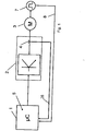
- Fig. 1 shows the circuit diagram of a conventional servo drive. It has a microcontroller 1 that is connected to an actuator 2. The signals from the actuator 2, which is power electronics, are fed to the motor 3. A current sensor 4 detects the current signals fed to the motor 3. The position of the rotor of the motor 3 is detected by a position encoder 7, the signals of which are fed to the microcontroller 1 via an encoder cable 8. The signals from the current sensor 4 are also fed to the microcontroller 1 via a line 28. The signals supplied via the cables 8, 28 are evaluated via an algorithm 5 of the microcontroller 1 and, if necessary, corresponding correction signals are supplied to the motor 3 via the actuator 2.
- the servo drive controls or regulates movements of machine axes.
- the movements of the machine axis are recorded with the position encoder 7. These movements can be rotary movements of the machine axis.
- Such machines are used, for example, for wire winding, wire straightening and the like.
- the machine axes can, however, also execute swiveling movements or shifting movements. Displacement movements occur, for example, with slides in packaging machines or with lifting mechanisms.
- the use of the encoder 7 is costly.
- the evaluation electronics 2 and the cabling in the form of the encoder cable 8 also lead to considerable costs.
- the position encoders 7 are very sensitive in use, and their reliability is limited depending on the application of the servo drive.
- the encoders 7 increase the overall volume of the servo drive.
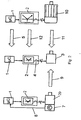
- Fig. 2 shows two known servo drives in the right and left representation.
- a motor 29, which is provided with the position encoder 7, is driven by the left servo drive. Its signals are fed to the microcontroller 1 via the encoder cable 8 in the manner described, the signals of which are fed to the actuator 2.
- a synchronous reluctance machine 10 is operated on the right servo drive. It is connected to the actuator 2, which in turn is connected to the microcontroller 1.
- the actuator 2 which in turn is connected to the microcontroller 1.
- the microcontroller 1 For the synchronous reluctance machine 10 a relatively large power electronics 2 is required.
- the synchronous reluctance machine 10 itself also has a large volume.
- the middle representation in Fig. 2 shows the circuit diagram of a servo drive with a permanent magnet synchronous motor 3.
- the servo drive has the microcontroller 1, which is connected to the actuator 2 in the form of power electronics.
- the engine 3 is operated with it.
- the current sensor 4 detects the current supplied by the actuator 2 to the motor 3.
- the motor 3 is a permanent magnet synchronous motor.
- the servo drive according to the invention is characterized in that it has no encoder cable 8 and no encoder 7. This is indicated by the dashed arrow 9 in Fig. 2 marked.
- the motor 3 is a permanent magnet synchronous motor, it is much smaller than the synchronous reluctance machine 10 (arrow 11).
- the permanent magnet synchronous motor 3 also requires significantly smaller power electronics 2 (arrow 12).
- the servo drive is thus characterized by a compact design that is also inexpensive to purchase.
- a synchronous reluctance machine is described, of which the rotor 26 is shown.
- the corresponding induction curve over the angle ⁇ from 0 ° to 90 ° is shown in the corresponding diagram.
- the rotor 24 has four rotor arms 30 which extend from a central area and are connected to one another at the outer end by a ring 31.
- the arms 30 each have an angular distance of 90 ° from one another.
- the inductance-angle diagram shows that the inductance L is in the range of Rotor arms 30 (0 ° and 90 °) is largest and smallest in the area between them at 45 °.
- Fig. 4 shows the conditions in a permanent magnet synchronous motor, of which the rotor 6 is shown.
- the rotor 6 has the arms 30 which are arranged at angular intervals of 90 ° from one another and are connected to one another at the outer edge by the ring 31.
- the arms 30 are at an angle ⁇ of 45 °, 135 °, 225 °, 315 °.
- the inductance L has the lowest value in the area of the recesses 32 and the highest value in the area of the arms 30.
- the inductance curve 16 thus has the highest value at 45 ° and the lowest value at 0 ° and 90 °.
- a test frequency 18 is injected via the power electronics 2 in certain operating states ( Figures 5 and 6 ).
- the rotor position is determined via the measured current that then sets in. This position is used both for commutation and for speed and position control.
- the microcontroller 1 is able, without a position encoder, as it is used in the known servo drives, to operate a field-oriented control in all load and speed states only with the current measurement.
- the test signal 18 which is preferably in a frequency range of about 200 to 400 Hz, is in the case of Fig. 5 injected at a position angle ⁇ of -45 °, based on the angular position of the permanent magnets 13.
- the associated vector diagram shows the current Itest in the form of the current space vector 19.
- the angle ⁇ indicates that the actual position detected by means of the test signal 18 is 0 ° from the target position deviates by 0 °. Accordingly, in a manner to be described, the servo drive is readjusted in such a way that the actual position corresponds to the setpoint position.
- Fig. 6 it is shown by way of example that the test signal 18 is injected in the position 0 °.
- the associated vector diagram shows that the current space vector Itest lies in the 0 ° direction, ie that the measured actual position 0 ° corresponds to the target position 0 °.
- the error signal is thus 0.
- Fig. 8 the left figure shows an example of the inductance curve 20 of the rotor 17 of the permanent magnet synchronous motor.
- this permanent magnet synchronous motor is brought into saturation in a current-controlled manner, namely once against the rotor magnetic field 22 and once in the direction of the rotor magnetic field 23.
- these induction curves 22, 23 resulting from the saturation current supply are shown by way of example.
- Fig. 9 In the left figure shows the rotor 17 with the inductance curve 20, which results when the motor is not energized. If it is energized, then the inductance curve 21 changes, like the illustration on the right in FIG Fig. 9 shows. The difference between the two induction curves 20 is denoted by ⁇ .
- the geometric inductance curve of the permanent magnet synchronous motor is dependent on the current supply to the motor, in particular when the rotor 17 is saturated.
- the position error can be described as a displacement about the axis of rotation of the rotor 17.
- the permanent magnet synchronous motor is measured beforehand and a table is determined which describes this shift ⁇ . This table is stored in microcontroller 1. When compensating for the position error ⁇ caused by saturation, this table is used, which is determined separately for each permanent magnet synchronous motor and stored in the microcontroller.
- a device 24 is provided. With it, the stator field is tracked to the rotating rotor 17 in order to eliminate the shift ⁇ .
- the test signal 18 is injected in the manner described and the position of the current space pointer 19 is determined using the measured current that is established. It is taken into account in the described saturation current flow.
- the device 24 sends out a signal ⁇ *, which results from the injected test signal 18 and indicates the current position of the rotor 17.
- This signal characterizes the described position error ⁇ , which is compensated for by a corresponding saturation current supply.
- the comparison values stored in table form in the microcontroller are used here.
- the position error ⁇ is canceled by the saturation compensation, which is shown in the figure below Fig. 9 is marked with ⁇ .
- the position compensation is advantageously carried out by means of a control.
- the rotor 17 has a special design that is based on Fig. 10 is described in more detail. This design is chosen with a view to the fact that the inductance-angle curve ( Figs. 3 and 4 ) approaches a straight line. Then it is difficult to regulate the motor.
- the design of the rotor 17 described below ensures that, even with the high currents, a curve of the inductance 16 results, as shown in FIG Figs. 3 and 4 is shown.
- the rotor design results in a high degree of efficiency.
- the reluctance torque is used to the maximum, which contributes to an optimal torque.
- the rotor 17 is formed by a laminated core 14, which consists of sheet metal lamellas lying on top of one another, which are firmly connected to one another in a suitable manner.
- the laminated core 14 has recesses 34 distributed over the circumference, which extend over the height of the laminated core 14 and are advantageously designed in the same way.
- the recesses 34 accommodate the permanent magnets 13.
- six recesses 34 and accordingly six permanent magnet stacks 13 are arranged evenly distributed over the circumference of the rotor 17, which are arranged in the manner of secants.
- the individual permanent magnets 13 are each formed identically and preferably have a rectangular shape.
- the permanent magnets 13 rest with their end faces against one another and with their long sides on the side walls of the recess 34.
- the permanent magnets 13 within the recess 34 are permanent magnets of the same type, with homopolar permanent magnets 13 being arranged within the recess 34.
- the poles of the permanent magnets 13 alternate over the circumference of the laminated core 14.
- Recesses 15 serving as flow barriers adjoin the end faces 35, 36 of the recesses 34. They are arranged in the laminated core 14 in such a way that they minimize the rotor losses and in this way contribute to a very high efficiency of the rotor 17.
- the recesses 15 extend from the end faces 35, 36 in the direction of the outer edge 37 of the laminated core 14 and end at a small distance from the edge 37 a small distance from the end faces 35, 36 of the recesses 34 extend over those adjacent to the jacket 37 of the laminated core 14
- the longitudinal side of the recesses 34 extend and end at a small distance from the laminated core jacket 37.
- the laminated core 14 is provided in the area between adjacent recesses 34 with a respective groove 38 which extends over the height of the laminated core 14.
- the grooves 38 are formed identically and open into the outer jacket of the laminated core 14. Their width steadily decreases radially inward.
- the side walls 39, 40 of the grooves 38 preferably merge into one another in an arc shape.
- the grooves 38 thus have a V-shape as seen in the axial direction of the laminated core 14.
- the grooves 38 each lie between two cutouts 15 of adjacent cutouts 34.
- the grooves 38 are advantageously used to reinforce the magnetic anisotropy of the laminated core 14.
- the laminated core 14 has a central opening 41 into which a rotor shaft (not shown) protrudes.
- a rotor shaft (not shown) protrudes.
- two form-fit elements 42 are provided, for example, into which corresponding counter-form-fit elements of the rotor shaft engage and thus produce a simple and reliable non-rotatable connection between the rotor 17 and the rotor shaft.
- the laminated core is provided with further recesses 43 which are arranged and designed in such a way that they do not impair the magnetic flux and lead to a considerable saving in weight.
- the lamellae which, when placed one on top of the other, form the laminated core 14 are designed in one piece. It is possible to produce the laminated core 14 also from individual partial laminated cores, which in turn are formed from partial lamellas. These partial laminated stacks are joined together in a known manner to form a complete laminated stacks 14.
- the full torque can be achieved in all operating states when the permanent magnet synchronous motor is in operation.
- the drive can be reliably positioned even under load.
- the servo drive enables a very high power density that is greater than the power density of synchronous reluctance machines or synchronous servomotors with position encoders.
- the permanent magnet synchronous motor requires less power than synchronous reluctance machines. This means that a smaller size can be used for the drive controller. Since the position encoder and the encoder cable are no longer necessary, the costs for the servo drive can be reduced considerably.
- the energy efficiency of the servo drive corresponds to the energy efficiency of synchronous servomotors with position encoders.
- the dynamic properties of the servo drive are better than other servo drives without a position encoder. The power requirement of the servo drive is also low.
Landscapes
- Engineering & Computer Science (AREA)
- Power Engineering (AREA)
- Control Of Ac Motors In General (AREA)
- Control Of Motors That Do Not Use Commutators (AREA)
Claims (3)
- Procédé de détermination de la position d'un rotor (6, 17, 26) d'un moteur synchrone à aimant permanent pour un servomoteur, pour lequel une régulation à orientation de champ est prévue pour la détermination de la position de rotor, pour lequel un signal d'essai de courant (18) est injecté et la position de rotor est déterminée à partir du courant en résultant, sachant que le moteur synchrone à aimant permanent est placé en saturation, une allure tension/courant définie est ensuite superposée à la tension/au courant en résultant, la variation d'inductance (L) en résultant est saisie, et la position du rotor (17) est de ce fait déterminée, sachant que l'allure (20 à 23) de l'inductance est saisie en tant que fonction de la position de rotor lors de l'alimentation en courant du rotor (17) et est comparée aux valeurs mémorisées, sachant que les valeurs mémorisées contiennent les erreurs de position (Δφ) du rotor (17) et les valeurs de courant nécessaires à la compensation de cette erreur de position, qu'un système (24) est prévu de préférence sous forme de tableaux et pour la correction de l'erreur de position (Δφ) due à la saturation, sachant qu'au moyen du signal d'essai (8) injecté, la position d'un vecteur de courant (19) est déterminée par le biais du courant mesuré s'instaurant, qui est pris en considération lors de l'alimentation en courant en saturation, sachant que le système (24) émet un signal (φ*), qui résulte en raison du signal d'essai (18) et affiche la position momentanée du rotor (17) et identifie l'erreur de position (Δφ) et qui adapte le champ de stator au rotor en rotation (17) pour compenser l'erreur de position (Δφ), caractérisé en ce que le moteur synchrone à aimant permanent est à courant régulé, lorsqu'il est placé en saturation et en ce que le rotor (17) est placé en saturation en régulation de courant, une fois en direction du champ magnétique du rotor et une fois à l'opposé de celle-ci.
- Procédé selon la revendication 1, caractérisé en ce que l'erreur de position (Δφ) est déterminée en tant que déplacement de la position autour de l'axe de rotation du rotor (17).
- Procédé selon la revendication 1 ou 2, caractérisé en ce que le signal d'essai de courant (18) est acheminé par un organe de réglage (2), qui est de préférence un système électronique de puissance.
Applications Claiming Priority (1)
| Application Number | Priority Date | Filing Date | Title |
|---|---|---|---|
| DE102015005478.3A DE102015005478A1 (de) | 2015-04-28 | 2015-04-28 | Servoantrieb, Verfahren zur Bestimmung der Position eines Rotors eines Permanentmagnetservomotors sowie Rotor zur Verwendung beim Servoantrieb und beim Verfahren |
Publications (3)
| Publication Number | Publication Date |
|---|---|
| EP3089351A2 EP3089351A2 (fr) | 2016-11-02 |
| EP3089351A3 EP3089351A3 (fr) | 2017-02-22 |
| EP3089351B1 true EP3089351B1 (fr) | 2021-11-10 |
Family
ID=55808926
Family Applications (1)
| Application Number | Title | Priority Date | Filing Date |
|---|---|---|---|
| EP16000903.1A Revoked EP3089351B1 (fr) | 2015-04-28 | 2016-04-21 | Procede de determination de la position d'un rotor d'un servomoteur a aimant permanent |
Country Status (2)
| Country | Link |
|---|---|
| EP (1) | EP3089351B1 (fr) |
| DE (1) | DE102015005478A1 (fr) |
Families Citing this family (2)
| Publication number | Priority date | Publication date | Assignee | Title |
|---|---|---|---|---|
| DE102019214051B4 (de) * | 2019-09-16 | 2021-07-15 | Zf Friedrichshafen Ag | Trommelantrieb einer Mischtrommel eines Fahrmischers |
| CN116362148B (zh) * | 2023-02-27 | 2023-09-05 | 湖南大学 | 一种高速永磁电机转子涡流损耗计算方法 |
Citations (5)
| Publication number | Priority date | Publication date | Assignee | Title |
|---|---|---|---|---|
| US6051946A (en) | 1997-09-12 | 2000-04-18 | Toyota Jidosha Kabushiki Kaisha | Electrical angle detection apparatus, method of detecting electrical angle, and motor control apparatus |
| EP1526635A2 (fr) | 2003-10-22 | 2005-04-27 | Fanuc Ltd | Procédé et dispositif de détection de la position d' un pôle magnétique |
| DE102007057499A1 (de) | 2006-11-30 | 2008-06-05 | Denso Corp., Kariya | System und Verfahren zum Steuern eines Motors unter Verwendung eines mit einem magnetischen Fluss zusammenhängenden Parameters |
| US20100171455A1 (en) | 2009-01-05 | 2010-07-08 | Gm Global Technology Operations, Inc. | Initial polarity detection for permanent magnet motor drives |
| US20140327379A1 (en) | 2013-05-03 | 2014-11-06 | Texas Instruments Incorporated | Position sensorless drive system and method for permanent magnet motors |
-
2015
- 2015-04-28 DE DE102015005478.3A patent/DE102015005478A1/de not_active Withdrawn
-
2016
- 2016-04-21 EP EP16000903.1A patent/EP3089351B1/fr not_active Revoked
Patent Citations (5)
| Publication number | Priority date | Publication date | Assignee | Title |
|---|---|---|---|---|
| US6051946A (en) | 1997-09-12 | 2000-04-18 | Toyota Jidosha Kabushiki Kaisha | Electrical angle detection apparatus, method of detecting electrical angle, and motor control apparatus |
| EP1526635A2 (fr) | 2003-10-22 | 2005-04-27 | Fanuc Ltd | Procédé et dispositif de détection de la position d' un pôle magnétique |
| DE102007057499A1 (de) | 2006-11-30 | 2008-06-05 | Denso Corp., Kariya | System und Verfahren zum Steuern eines Motors unter Verwendung eines mit einem magnetischen Fluss zusammenhängenden Parameters |
| US20100171455A1 (en) | 2009-01-05 | 2010-07-08 | Gm Global Technology Operations, Inc. | Initial polarity detection for permanent magnet motor drives |
| US20140327379A1 (en) | 2013-05-03 | 2014-11-06 | Texas Instruments Incorporated | Position sensorless drive system and method for permanent magnet motors |
Non-Patent Citations (2)
| Title |
|---|
| FERREIRA OSCAR CABRAL: "Kompensation der Betriebsabhängigkeiten der Anisotropie im Hinblick auf die geberlose Regelung von Synchronmaschinen", DISSERTATION, 7 December 2007 (2007-12-07), pages III-XII, 1 - 143, XP055950336 |
| JOACHIM HOLTZ: "Initial Rotor Polarity Detection and Sensorless Control of PM Synchronous Machines", THE 2006 IEEE INDUSTRY APPLICATIONS CONFERENCE FORTY-FIRST IAS ANNUAL MEETING, CONFERENCE RECORD OF, IEEE, PISCATAWAY, NJ, US, 1 October 2006 (2006-10-01), Piscataway, NJ, US , pages 2040 - 2047, XP031026303, ISBN: 978-1-4244-0364-6 |
Also Published As
| Publication number | Publication date |
|---|---|
| DE102015005478A1 (de) | 2016-11-03 |
| EP3089351A3 (fr) | 2017-02-22 |
| EP3089351A2 (fr) | 2016-11-02 |
Similar Documents
| Publication | Publication Date | Title |
|---|---|---|
| EP2601739B1 (fr) | Procédé et circuiterie pour vérifier la position du rotor d'une machine synchrone | |
| DE112014006430B4 (de) | Synchron-Reluktanzmotor | |
| DE60315534T2 (de) | Drehwinkel- und Drehmomentsensor und Lenkung | |
| DE60311407T2 (de) | Elektrisches Motorgerät und Servolenksystem | |
| DE102004011477A1 (de) | Mehrphasiger Elektromotor | |
| DE102014014487A1 (de) | Luftfahrzeug mit einer Synchronreluktanzmaschine | |
| DE112014006465T5 (de) | Magnetische Vorrichtung zur Positionserfassung und Verfahren zur magnetischen Positionserfassung | |
| DE102014222064B4 (de) | Elektrische Maschine | |
| WO2015067497A2 (fr) | Machine électrique | |
| DE102011119229A1 (de) | Korrekturverfahren für eine Position eines magnetischen Pols eines Motors | |
| EP2047585B1 (fr) | Moteur synchrone, système de moteur sans codeur et procédé de fonctionnement d'un système de moteur sans codeur avec un moteur synchrone | |
| WO2014049007A1 (fr) | Pièce active d'une machine électrique, palier magnétique radial et procédé pour produire un palier magnétique radial | |
| DE102010043970A1 (de) | Elektrische Maschine für einen Lenkantrieb | |
| EP2942858B1 (fr) | Paquet de tôles de rotor | |
| DE102012212775A1 (de) | Rotoranordnung für eine elektrische Maschine | |
| EP3089351B1 (fr) | Procede de determination de la position d'un rotor d'un servomoteur a aimant permanent | |
| EP2807721A2 (fr) | Machine électrique | |
| DE102014002100A1 (de) | Synchronmotor mit hoher Ansprechempfindlichkeit | |
| DE102009029155A1 (de) | Verfahren und Vorrichtung zur Bestimmung einer Rotorlage einer Synchronmaschine | |
| EP3016270A2 (fr) | Procédé et système de circuit de stabilisation de la position d'un rotor par rapport à un stator dans un moteur électrique | |
| EP3261234B1 (fr) | Machine électrique dotée d'un rotor | |
| DE102019108047A1 (de) | Rotor für einen Permanentmagnet-Synchronmotor, Permanentmagnet-Synchronmotor und Fahrzeug | |
| DE102015107014B4 (de) | Stator für einen Reluktanzmotor, Reluktanzmotor, Verfahren zur Steuerung eines Reluktanzmotors sowie Ansteuerelektronik für einen Reluktanzmotor | |
| DE102021212936A1 (de) | Lenkvorrichtung und -verfahren | |
| DE102021107894A1 (de) | Leistungsinduktivität mit nachgiebigen stiften und batterie-schnittstelle |
Legal Events
| Date | Code | Title | Description |
|---|---|---|---|
| PUAI | Public reference made under article 153(3) epc to a published international application that has entered the european phase |
Free format text: ORIGINAL CODE: 0009012 |
|
| AK | Designated contracting states |
Kind code of ref document: A2 Designated state(s): AL AT BE BG CH CY CZ DE DK EE ES FI FR GB GR HR HU IE IS IT LI LT LU LV MC MK MT NL NO PL PT RO RS SE SI SK SM TR |
|
| AX | Request for extension of the european patent |
Extension state: BA ME |
|
| PUAL | Search report despatched |
Free format text: ORIGINAL CODE: 0009013 |
|
| AK | Designated contracting states |
Kind code of ref document: A3 Designated state(s): AL AT BE BG CH CY CZ DE DK EE ES FI FR GB GR HR HU IE IS IT LI LT LU LV MC MK MT NL NO PL PT RO RS SE SI SK SM TR |
|
| AX | Request for extension of the european patent |
Extension state: BA ME |
|
| RIC1 | Information provided on ipc code assigned before grant |
Ipc: H02P 21/24 20160101ALI20170116BHEP Ipc: H02P 25/022 20160101ALI20170116BHEP Ipc: H02P 6/18 20160101AFI20170116BHEP |
|
| STAA | Information on the status of an ep patent application or granted ep patent |
Free format text: STATUS: REQUEST FOR EXAMINATION WAS MADE |
|
| 17P | Request for examination filed |
Effective date: 20170822 |
|
| RBV | Designated contracting states (corrected) |
Designated state(s): AL AT BE BG CH CY CZ DE DK EE ES FI FR GB GR HR HU IE IS IT LI LT LU LV MC MK MT NL NO PL PT RO RS SE SI SK SM TR |
|
| STAA | Information on the status of an ep patent application or granted ep patent |
Free format text: STATUS: EXAMINATION IS IN PROGRESS |
|
| 17Q | First examination report despatched |
Effective date: 20180828 |
|
| GRAP | Despatch of communication of intention to grant a patent |
Free format text: ORIGINAL CODE: EPIDOSNIGR1 |
|
| STAA | Information on the status of an ep patent application or granted ep patent |
Free format text: STATUS: GRANT OF PATENT IS INTENDED |
|
| RIC1 | Information provided on ipc code assigned before grant |
Ipc: H02P 6/18 20160101AFI20210430BHEP Ipc: H02P 25/022 20160101ALI20210430BHEP Ipc: H02P 21/24 20160101ALI20210430BHEP Ipc: H02P 25/024 20160101ALI20210430BHEP |
|
| INTG | Intention to grant announced |
Effective date: 20210608 |
|
| GRAS | Grant fee paid |
Free format text: ORIGINAL CODE: EPIDOSNIGR3 |
|
| GRAA | (expected) grant |
Free format text: ORIGINAL CODE: 0009210 |
|
| STAA | Information on the status of an ep patent application or granted ep patent |
Free format text: STATUS: THE PATENT HAS BEEN GRANTED |
|
| AK | Designated contracting states |
Kind code of ref document: B1 Designated state(s): AL AT BE BG CH CY CZ DE DK EE ES FI FR GB GR HR HU IE IS IT LI LT LU LV MC MK MT NL NO PL PT RO RS SE SI SK SM TR |
|
| REG | Reference to a national code |
Ref country code: GB Ref legal event code: FG4D Free format text: NOT ENGLISH |
|
| REG | Reference to a national code |
Ref country code: AT Ref legal event code: REF Ref document number: 1446997 Country of ref document: AT Kind code of ref document: T Effective date: 20211115 Ref country code: CH Ref legal event code: EP |
|
| REG | Reference to a national code |
Ref country code: DE Ref legal event code: R096 Ref document number: 502016014105 Country of ref document: DE |
|
| REG | Reference to a national code |
Ref country code: IE Ref legal event code: FG4D Free format text: LANGUAGE OF EP DOCUMENT: GERMAN |
|
| REG | Reference to a national code |
Ref country code: LT Ref legal event code: MG9D |
|
| REG | Reference to a national code |
Ref country code: NL Ref legal event code: MP Effective date: 20211110 |
|
| PG25 | Lapsed in a contracting state [announced via postgrant information from national office to epo] |
Ref country code: RS Free format text: LAPSE BECAUSE OF FAILURE TO SUBMIT A TRANSLATION OF THE DESCRIPTION OR TO PAY THE FEE WITHIN THE PRESCRIBED TIME-LIMIT Effective date: 20211110 Ref country code: LT Free format text: LAPSE BECAUSE OF FAILURE TO SUBMIT A TRANSLATION OF THE DESCRIPTION OR TO PAY THE FEE WITHIN THE PRESCRIBED TIME-LIMIT Effective date: 20211110 Ref country code: FI Free format text: LAPSE BECAUSE OF FAILURE TO SUBMIT A TRANSLATION OF THE DESCRIPTION OR TO PAY THE FEE WITHIN THE PRESCRIBED TIME-LIMIT Effective date: 20211110 Ref country code: BG Free format text: LAPSE BECAUSE OF FAILURE TO SUBMIT A TRANSLATION OF THE DESCRIPTION OR TO PAY THE FEE WITHIN THE PRESCRIBED TIME-LIMIT Effective date: 20220210 |
|
| PG25 | Lapsed in a contracting state [announced via postgrant information from national office to epo] |
Ref country code: IS Free format text: LAPSE BECAUSE OF FAILURE TO SUBMIT A TRANSLATION OF THE DESCRIPTION OR TO PAY THE FEE WITHIN THE PRESCRIBED TIME-LIMIT Effective date: 20220310 Ref country code: SE Free format text: LAPSE BECAUSE OF FAILURE TO SUBMIT A TRANSLATION OF THE DESCRIPTION OR TO PAY THE FEE WITHIN THE PRESCRIBED TIME-LIMIT Effective date: 20211110 Ref country code: PT Free format text: LAPSE BECAUSE OF FAILURE TO SUBMIT A TRANSLATION OF THE DESCRIPTION OR TO PAY THE FEE WITHIN THE PRESCRIBED TIME-LIMIT Effective date: 20220310 Ref country code: PL Free format text: LAPSE BECAUSE OF FAILURE TO SUBMIT A TRANSLATION OF THE DESCRIPTION OR TO PAY THE FEE WITHIN THE PRESCRIBED TIME-LIMIT Effective date: 20211110 Ref country code: NO Free format text: LAPSE BECAUSE OF FAILURE TO SUBMIT A TRANSLATION OF THE DESCRIPTION OR TO PAY THE FEE WITHIN THE PRESCRIBED TIME-LIMIT Effective date: 20220210 Ref country code: NL Free format text: LAPSE BECAUSE OF FAILURE TO SUBMIT A TRANSLATION OF THE DESCRIPTION OR TO PAY THE FEE WITHIN THE PRESCRIBED TIME-LIMIT Effective date: 20211110 Ref country code: LV Free format text: LAPSE BECAUSE OF FAILURE TO SUBMIT A TRANSLATION OF THE DESCRIPTION OR TO PAY THE FEE WITHIN THE PRESCRIBED TIME-LIMIT Effective date: 20211110 Ref country code: HR Free format text: LAPSE BECAUSE OF FAILURE TO SUBMIT A TRANSLATION OF THE DESCRIPTION OR TO PAY THE FEE WITHIN THE PRESCRIBED TIME-LIMIT Effective date: 20211110 Ref country code: GR Free format text: LAPSE BECAUSE OF FAILURE TO SUBMIT A TRANSLATION OF THE DESCRIPTION OR TO PAY THE FEE WITHIN THE PRESCRIBED TIME-LIMIT Effective date: 20220211 Ref country code: ES Free format text: LAPSE BECAUSE OF FAILURE TO SUBMIT A TRANSLATION OF THE DESCRIPTION OR TO PAY THE FEE WITHIN THE PRESCRIBED TIME-LIMIT Effective date: 20211110 |
|
| REG | Reference to a national code |
Ref country code: DE Ref legal event code: R026 Ref document number: 502016014105 Country of ref document: DE |
|
| PG25 | Lapsed in a contracting state [announced via postgrant information from national office to epo] |
Ref country code: SM Free format text: LAPSE BECAUSE OF FAILURE TO SUBMIT A TRANSLATION OF THE DESCRIPTION OR TO PAY THE FEE WITHIN THE PRESCRIBED TIME-LIMIT Effective date: 20211110 Ref country code: SK Free format text: LAPSE BECAUSE OF FAILURE TO SUBMIT A TRANSLATION OF THE DESCRIPTION OR TO PAY THE FEE WITHIN THE PRESCRIBED TIME-LIMIT Effective date: 20211110 Ref country code: RO Free format text: LAPSE BECAUSE OF FAILURE TO SUBMIT A TRANSLATION OF THE DESCRIPTION OR TO PAY THE FEE WITHIN THE PRESCRIBED TIME-LIMIT Effective date: 20211110 Ref country code: EE Free format text: LAPSE BECAUSE OF FAILURE TO SUBMIT A TRANSLATION OF THE DESCRIPTION OR TO PAY THE FEE WITHIN THE PRESCRIBED TIME-LIMIT Effective date: 20211110 Ref country code: DK Free format text: LAPSE BECAUSE OF FAILURE TO SUBMIT A TRANSLATION OF THE DESCRIPTION OR TO PAY THE FEE WITHIN THE PRESCRIBED TIME-LIMIT Effective date: 20211110 Ref country code: CZ Free format text: LAPSE BECAUSE OF FAILURE TO SUBMIT A TRANSLATION OF THE DESCRIPTION OR TO PAY THE FEE WITHIN THE PRESCRIBED TIME-LIMIT Effective date: 20211110 |
|
| PLBI | Opposition filed |
Free format text: ORIGINAL CODE: 0009260 |
|
| PLAB | Opposition data, opponent's data or that of the opponent's representative modified |
Free format text: ORIGINAL CODE: 0009299OPPO |
|
| PLAX | Notice of opposition and request to file observation + time limit sent |
Free format text: ORIGINAL CODE: EPIDOSNOBS2 |
|
| 26 | Opposition filed |
Opponent name: SEW-EURODRIVE GMBH & CO. KG Effective date: 20220727 |
|
| R26 | Opposition filed (corrected) |
Opponent name: SEW-EURODRIVE GMBH & CO. KG Effective date: 20220727 |
|
| PG25 | Lapsed in a contracting state [announced via postgrant information from national office to epo] |
Ref country code: AL Free format text: LAPSE BECAUSE OF FAILURE TO SUBMIT A TRANSLATION OF THE DESCRIPTION OR TO PAY THE FEE WITHIN THE PRESCRIBED TIME-LIMIT Effective date: 20211110 |
|
| PG25 | Lapsed in a contracting state [announced via postgrant information from national office to epo] |
Ref country code: SI Free format text: LAPSE BECAUSE OF FAILURE TO SUBMIT A TRANSLATION OF THE DESCRIPTION OR TO PAY THE FEE WITHIN THE PRESCRIBED TIME-LIMIT Effective date: 20211110 |
|
| PLBB | Reply of patent proprietor to notice(s) of opposition received |
Free format text: ORIGINAL CODE: EPIDOSNOBS3 |
|
| REG | Reference to a national code |
Ref country code: BE Ref legal event code: MM Effective date: 20220430 |
|
| PG25 | Lapsed in a contracting state [announced via postgrant information from national office to epo] |
Ref country code: MC Free format text: LAPSE BECAUSE OF FAILURE TO SUBMIT A TRANSLATION OF THE DESCRIPTION OR TO PAY THE FEE WITHIN THE PRESCRIBED TIME-LIMIT Effective date: 20211110 Ref country code: LU Free format text: LAPSE BECAUSE OF NON-PAYMENT OF DUE FEES Effective date: 20220421 |
|
| PG25 | Lapsed in a contracting state [announced via postgrant information from national office to epo] |
Ref country code: BE Free format text: LAPSE BECAUSE OF NON-PAYMENT OF DUE FEES Effective date: 20220430 |
|
| PG25 | Lapsed in a contracting state [announced via postgrant information from national office to epo] |
Ref country code: IE Free format text: LAPSE BECAUSE OF NON-PAYMENT OF DUE FEES Effective date: 20220421 |
|
| RDAF | Communication despatched that patent is revoked |
Free format text: ORIGINAL CODE: EPIDOSNREV1 |
|
| APBM | Appeal reference recorded |
Free format text: ORIGINAL CODE: EPIDOSNREFNO |
|
| APBP | Date of receipt of notice of appeal recorded |
Free format text: ORIGINAL CODE: EPIDOSNNOA2O |
|
| APAH | Appeal reference modified |
Free format text: ORIGINAL CODE: EPIDOSCREFNO |
|
| PG25 | Lapsed in a contracting state [announced via postgrant information from national office to epo] |
Ref country code: HU Free format text: LAPSE BECAUSE OF FAILURE TO SUBMIT A TRANSLATION OF THE DESCRIPTION OR TO PAY THE FEE WITHIN THE PRESCRIBED TIME-LIMIT; INVALID AB INITIO Effective date: 20160421 |
|
| PG25 | Lapsed in a contracting state [announced via postgrant information from national office to epo] |
Ref country code: MK Free format text: LAPSE BECAUSE OF FAILURE TO SUBMIT A TRANSLATION OF THE DESCRIPTION OR TO PAY THE FEE WITHIN THE PRESCRIBED TIME-LIMIT Effective date: 20211110 Ref country code: CY Free format text: LAPSE BECAUSE OF FAILURE TO SUBMIT A TRANSLATION OF THE DESCRIPTION OR TO PAY THE FEE WITHIN THE PRESCRIBED TIME-LIMIT Effective date: 20211110 |
|
| PGFP | Annual fee paid to national office [announced via postgrant information from national office to epo] |
Ref country code: GB Payment date: 20240320 Year of fee payment: 9 |
|
| APBQ | Date of receipt of statement of grounds of appeal recorded |
Free format text: ORIGINAL CODE: EPIDOSNNOA3O |
|
| PGFP | Annual fee paid to national office [announced via postgrant information from national office to epo] |
Ref country code: FR Payment date: 20240307 Year of fee payment: 9 |
|
| APAH | Appeal reference modified |
Free format text: ORIGINAL CODE: EPIDOSCREFNO |
|
| PGFP | Annual fee paid to national office [announced via postgrant information from national office to epo] |
Ref country code: DE Payment date: 20240625 Year of fee payment: 9 |
|
| PGFP | Annual fee paid to national office [announced via postgrant information from national office to epo] |
Ref country code: CH Payment date: 20240501 Year of fee payment: 9 |
|
| PGFP | Annual fee paid to national office [announced via postgrant information from national office to epo] |
Ref country code: AT Payment date: 20240410 Year of fee payment: 9 |
|
| PGFP | Annual fee paid to national office [announced via postgrant information from national office to epo] |
Ref country code: IT Payment date: 20240417 Year of fee payment: 9 |
|
| PG25 | Lapsed in a contracting state [announced via postgrant information from national office to epo] |
Ref country code: MT Free format text: LAPSE BECAUSE OF FAILURE TO SUBMIT A TRANSLATION OF THE DESCRIPTION OR TO PAY THE FEE WITHIN THE PRESCRIBED TIME-LIMIT Effective date: 20211110 |
|
| REG | Reference to a national code |
Ref country code: DE Ref legal event code: R103 Ref document number: 502016014105 Country of ref document: DE Ref country code: DE Ref legal event code: R064 Ref document number: 502016014105 Country of ref document: DE |
|
| APBU | Appeal procedure closed |
Free format text: ORIGINAL CODE: EPIDOSNNOA9O |
|
| RDAG | Patent revoked |
Free format text: ORIGINAL CODE: 0009271 |
|
| STAA | Information on the status of an ep patent application or granted ep patent |
Free format text: STATUS: PATENT REVOKED |
|
| REG | Reference to a national code |
Ref country code: CH Ref legal event code: PL |
|
| 27W | Patent revoked |
Effective date: 20250310 |
|
| GBPR | Gb: patent revoked under art. 102 of the ep convention designating the uk as contracting state |
Effective date: 20250310 |
|
| PG25 | Lapsed in a contracting state [announced via postgrant information from national office to epo] |
Ref country code: FR Free format text: LAPSE BECAUSE OF NON-PAYMENT OF DUE FEES Effective date: 20250310 |
|
| REG | Reference to a national code |
Ref country code: AT Ref legal event code: MA03 Ref document number: 1446997 Country of ref document: AT Kind code of ref document: T Effective date: 20250310 |
|
| PG25 | Lapsed in a contracting state [announced via postgrant information from national office to epo] |
Ref country code: TR Free format text: LAPSE BECAUSE OF FAILURE TO SUBMIT A TRANSLATION OF THE DESCRIPTION OR TO PAY THE FEE WITHIN THE PRESCRIBED TIME-LIMIT Effective date: 20211110 |