EP3089687B1 - Cathéter d'ablation - Google Patents
Cathéter d'ablation Download PDFInfo
- Publication number
- EP3089687B1 EP3089687B1 EP15704691.3A EP15704691A EP3089687B1 EP 3089687 B1 EP3089687 B1 EP 3089687B1 EP 15704691 A EP15704691 A EP 15704691A EP 3089687 B1 EP3089687 B1 EP 3089687B1
- Authority
- EP
- European Patent Office
- Prior art keywords
- shaft
- catheter
- electrodes
- deflection
- manipulatable
- Prior art date
- Legal status (The legal status is an assumption and is not a legal conclusion. Google has not performed a legal analysis and makes no representation as to the accuracy of the status listed.)
- Active
Links
Images



Classifications
-
- A—HUMAN NECESSITIES
- A61—MEDICAL OR VETERINARY SCIENCE; HYGIENE
- A61B—DIAGNOSIS; SURGERY; IDENTIFICATION
- A61B18/00—Surgical instruments, devices or methods for transferring non-mechanical forms of energy to or from the body
- A61B18/04—Surgical instruments, devices or methods for transferring non-mechanical forms of energy to or from the body by heating
- A61B18/12—Surgical instruments, devices or methods for transferring non-mechanical forms of energy to or from the body by heating by passing a current through the tissue to be heated, e.g. high-frequency current
- A61B18/14—Probes or electrodes therefor
- A61B18/1492—Probes or electrodes therefor having a flexible, catheter-like structure, e.g. for heart ablation
-
- A—HUMAN NECESSITIES
- A61—MEDICAL OR VETERINARY SCIENCE; HYGIENE
- A61B—DIAGNOSIS; SURGERY; IDENTIFICATION
- A61B18/00—Surgical instruments, devices or methods for transferring non-mechanical forms of energy to or from the body
- A61B18/04—Surgical instruments, devices or methods for transferring non-mechanical forms of energy to or from the body by heating
- A61B18/12—Surgical instruments, devices or methods for transferring non-mechanical forms of energy to or from the body by heating by passing a current through the tissue to be heated, e.g. high-frequency current
- A61B18/1206—Generators therefor
-
- A—HUMAN NECESSITIES
- A61—MEDICAL OR VETERINARY SCIENCE; HYGIENE
- A61M—DEVICES FOR INTRODUCING MEDIA INTO, OR ONTO, THE BODY; DEVICES FOR TRANSDUCING BODY MEDIA OR FOR TAKING MEDIA FROM THE BODY; DEVICES FOR PRODUCING OR ENDING SLEEP OR STUPOR
- A61M25/00—Catheters; Hollow probes
- A61M25/01—Introducing, guiding, advancing, emplacing or holding catheters
- A61M25/0105—Steering means as part of the catheter or advancing means; Markers for positioning
- A61M25/0133—Tip steering devices
- A61M25/0147—Tip steering devices with movable mechanical means, e.g. pull wires
-
- A—HUMAN NECESSITIES
- A61—MEDICAL OR VETERINARY SCIENCE; HYGIENE
- A61N—ELECTROTHERAPY; MAGNETOTHERAPY; RADIATION THERAPY; ULTRASOUND THERAPY
- A61N1/00—Electrotherapy; Circuits therefor
- A61N1/18—Applying electric currents by contact electrodes
- A61N1/20—Applying electric currents by contact electrodes continuous direct currents
- A61N1/205—Applying electric currents by contact electrodes continuous direct currents for promoting a biological process
-
- A—HUMAN NECESSITIES
- A61—MEDICAL OR VETERINARY SCIENCE; HYGIENE
- A61B—DIAGNOSIS; SURGERY; IDENTIFICATION
- A61B17/00—Surgical instruments, devices or methods
- A61B2017/00526—Methods of manufacturing
-
- A—HUMAN NECESSITIES
- A61—MEDICAL OR VETERINARY SCIENCE; HYGIENE
- A61B—DIAGNOSIS; SURGERY; IDENTIFICATION
- A61B17/00—Surgical instruments, devices or methods
- A61B2017/00831—Material properties
- A61B2017/00867—Material properties shape memory effect
-
- A—HUMAN NECESSITIES
- A61—MEDICAL OR VETERINARY SCIENCE; HYGIENE
- A61B—DIAGNOSIS; SURGERY; IDENTIFICATION
- A61B18/00—Surgical instruments, devices or methods for transferring non-mechanical forms of energy to or from the body
- A61B2018/00053—Mechanical features of the instrument of device
- A61B2018/0016—Energy applicators arranged in a two- or three dimensional array
-
- A—HUMAN NECESSITIES
- A61—MEDICAL OR VETERINARY SCIENCE; HYGIENE
- A61B—DIAGNOSIS; SURGERY; IDENTIFICATION
- A61B18/00—Surgical instruments, devices or methods for transferring non-mechanical forms of energy to or from the body
- A61B2018/00315—Surgical instruments, devices or methods for transferring non-mechanical forms of energy to or from the body for treatment of particular body parts
- A61B2018/00345—Vascular system
- A61B2018/00351—Heart
- A61B2018/00363—Epicardium
-
- A—HUMAN NECESSITIES
- A61—MEDICAL OR VETERINARY SCIENCE; HYGIENE
- A61B—DIAGNOSIS; SURGERY; IDENTIFICATION
- A61B18/00—Surgical instruments, devices or methods for transferring non-mechanical forms of energy to or from the body
- A61B2018/00571—Surgical instruments, devices or methods for transferring non-mechanical forms of energy to or from the body for achieving a particular surgical effect
- A61B2018/00577—Ablation
-
- A—HUMAN NECESSITIES
- A61—MEDICAL OR VETERINARY SCIENCE; HYGIENE
- A61B—DIAGNOSIS; SURGERY; IDENTIFICATION
- A61B18/00—Surgical instruments, devices or methods for transferring non-mechanical forms of energy to or from the body
- A61B2018/00571—Surgical instruments, devices or methods for transferring non-mechanical forms of energy to or from the body for achieving a particular surgical effect
- A61B2018/00613—Irreversible electroporation
-
- A—HUMAN NECESSITIES
- A61—MEDICAL OR VETERINARY SCIENCE; HYGIENE
- A61B—DIAGNOSIS; SURGERY; IDENTIFICATION
- A61B18/00—Surgical instruments, devices or methods for transferring non-mechanical forms of energy to or from the body
- A61B18/04—Surgical instruments, devices or methods for transferring non-mechanical forms of energy to or from the body by heating
- A61B18/12—Surgical instruments, devices or methods for transferring non-mechanical forms of energy to or from the body by heating by passing a current through the tissue to be heated, e.g. high-frequency current
- A61B18/1206—Generators therefor
- A61B2018/1266—Generators therefor with DC current output
-
- A—HUMAN NECESSITIES
- A61—MEDICAL OR VETERINARY SCIENCE; HYGIENE
- A61B—DIAGNOSIS; SURGERY; IDENTIFICATION
- A61B18/00—Surgical instruments, devices or methods for transferring non-mechanical forms of energy to or from the body
- A61B18/04—Surgical instruments, devices or methods for transferring non-mechanical forms of energy to or from the body by heating
- A61B18/12—Surgical instruments, devices or methods for transferring non-mechanical forms of energy to or from the body by heating by passing a current through the tissue to be heated, e.g. high-frequency current
- A61B18/14—Probes or electrodes therefor
- A61B2018/1405—Electrodes having a specific shape
- A61B2018/1407—Loop
-
- A—HUMAN NECESSITIES
- A61—MEDICAL OR VETERINARY SCIENCE; HYGIENE
- A61B—DIAGNOSIS; SURGERY; IDENTIFICATION
- A61B18/00—Surgical instruments, devices or methods for transferring non-mechanical forms of energy to or from the body
- A61B18/04—Surgical instruments, devices or methods for transferring non-mechanical forms of energy to or from the body by heating
- A61B18/12—Surgical instruments, devices or methods for transferring non-mechanical forms of energy to or from the body by heating by passing a current through the tissue to be heated, e.g. high-frequency current
- A61B18/14—Probes or electrodes therefor
- A61B2018/1467—Probes or electrodes therefor using more than two electrodes on a single probe
-
- A—HUMAN NECESSITIES
- A61—MEDICAL OR VETERINARY SCIENCE; HYGIENE
- A61M—DEVICES FOR INTRODUCING MEDIA INTO, OR ONTO, THE BODY; DEVICES FOR TRANSDUCING BODY MEDIA OR FOR TAKING MEDIA FROM THE BODY; DEVICES FOR PRODUCING OR ENDING SLEEP OR STUPOR
- A61M25/00—Catheters; Hollow probes
- A61M25/01—Introducing, guiding, advancing, emplacing or holding catheters
- A61M25/0105—Steering means as part of the catheter or advancing means; Markers for positioning
- A61M25/0133—Tip steering devices
- A61M2025/0163—Looped catheters
-
- A—HUMAN NECESSITIES
- A61—MEDICAL OR VETERINARY SCIENCE; HYGIENE
- A61M—DEVICES FOR INTRODUCING MEDIA INTO, OR ONTO, THE BODY; DEVICES FOR TRANSDUCING BODY MEDIA OR FOR TAKING MEDIA FROM THE BODY; DEVICES FOR PRODUCING OR ENDING SLEEP OR STUPOR
- A61M2205/00—General characteristics of the apparatus
- A61M2205/02—General characteristics of the apparatus characterised by a particular materials
- A61M2205/0266—Shape memory materials
-
- A—HUMAN NECESSITIES
- A61—MEDICAL OR VETERINARY SCIENCE; HYGIENE
- A61N—ELECTROTHERAPY; MAGNETOTHERAPY; RADIATION THERAPY; ULTRASOUND THERAPY
- A61N1/00—Electrotherapy; Circuits therefor
- A61N1/02—Details
- A61N1/04—Electrodes
- A61N1/05—Electrodes for implantation or insertion into the body, e.g. heart electrode
- A61N1/0587—Epicardial electrode systems; Endocardial electrodes piercing the pericardium
Definitions
- the present disclosure relates to medical catheters for electrically isolating tissue, and more particularly to catheters for delivering ablation energy via multiple electrodes arranged in a plane substantially aligned with or otherwise parallel to a longitudinal axis of the catheter.
- EP 2 241 279 A1 discloses an epicardial mapping and ablation catheter.
- US 2005/0261672 A1 discloses systems and methods for selective denervation of heart dysrhythmias.
- US 5,454,370 A discloses a mapping and ablation electrode configuration.
- a catheter according to claim 1 and a system according to claim 7 are provided.
- Preferred embodiments are defined in the dependent claims.
- a method involving positioning a plurality of electrodes on a distal portion of an ablation catheter shaft is also disclosed herein, however, this method does not form part of the invention.
- the disclosure is generally directed to medical devices. Devices and techniques are disclosed that enable multiple electrodes to be positioned proximate organic tissue, such as human tissue.
- the electrodes may be used to, for example, pass energy to ablate the tissue.
- the ablation is performed using direct current (DC) or alternating current (AC) current, such that an appropriate quantity of energy can irreversibly electroporate cells of the tissue, which can address physiological issues such as, for example, atrial fibrillation or flutter, ventricular tachycardia, and/or other electrophysiological issues in addition to other issues treatable by ablation (e.g. renal denervation, etc.).
- an externally applied electric field is applied to a cell which causes the cell wall to become permeable. If the pulse duration and wave form exceed the voltage threshold for the cell membrane, the cell wall is irreversibly damaged this process is known as irreversible electroporation (IRE). While embodiments described herein may be described in terms of cardiac treatments, the disclosure is not limited thereto.
- a medical catheter in one embodiment, includes a shaft and a distal segment.
- the distal segment of the shaft includes a plurality of electrodes that are configured in a plane arranged to deviate from the longitudinal axis of the shaft, where the electrode plane is substantially aligned with the longitudinal axis of the shaft.
- This arrangement provides, among other things, one manner of positioning the catheter electrodes against tissue in situations where the catheter can be moved along the tissue surface.
- One representative example of such a situation is in connection with epicardial ablation procedures, where the pericardium is intentionally breached in order to advance the medical catheters described herein to the epicardial surface and position the electrodes against the tissue for electroporation ablation procedures.
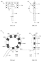
- FIG. 1A is a block diagram of one embodiment of a medical device 100 in accordance with the disclosure.
- a front view of the medical device 100 depicts at least a shaft 102 and a shaft extension 104.
- the shaft may represent a catheter shaft, such as a flexible epicardial catheter shaft capable of being introduced (by way of separate introducer or not) into a body such that the shaft extension 104 is positioned proximate a tissue target, such as the epicardium in order to perform epicardial ablation procedures.
- the shaft extension includes a plurality of electrodes 106.
- each of the electrodes 106 is coupled to a respective conductor (not shown) such as a respective current-carrying wire.
- tissue necrosis on which the electrodes 106 are positioned can be effected.
- RF energy can be passed to the electrodes 106, which enables tissue to be heated such that tissue necrosis can impact undesirable electrical impulses that trigger abnormal cardiac activity.
- Other types of ablation may also be effected, such as cryoablation, DC ablation, etc.
- the catheters described herein facilitate DC or AC ablation techniques, such as causing tissue necrosis by way of irreversible electroporation through application of current to the tissue.
- DC or AC ablation techniques such as causing tissue necrosis by way of irreversible electroporation through application of current to the tissue.
- the tissue areas contacting the tissue delivery locations become permanently nonconductive.
- the need for repositioning the catheter multiple times for creating an electrical isolation between two areas of cardiac tissue is reduced.
- a relative long length of cardiac tissue can be treated in a single operation, reducing the procedure time. Such treatments may be applied, for example, during approximately 5 ms of between 200 and 500 Joule.
- the electrodes 106 of the shaft extension 104 are positioned in a plane, that is, substantially positioned in two dimensions. This plane of electrodes is aligned with the longitudinal axis of the shaft 102.
- FIG. 1B depicts the medical device 100, showing both the shaft 102 and shaft extension 104 from a side view. As can be seen, the shaft extension 104, which is positioned in a planar fashion, aligns with the shaft 102 such that the two segments 102, 104 are aligned, or parallel.
- the catheter 100 includes a shaft 102 and a distal segment represented by the shaft extension 104. where the distal segment includes a plurality of electrodes 106 that are configured in a plane and arranged to deviate from the longitudinal axis of the shaft 108 (see FIG. 1A , where the electrodes 106 are not aligned with the axis 108 in the front view), however where the electrode plane formed by the electrodes 106 is substantially aligned with the longitudinal axis 108 of the shaft (see FIG. 1B ).
- FIG. 2A is another representative embodiment of a medical catheter 200 having a shaft 202 and a shaft extension 204.
- the shaft extension 204 is implemented by a distal portion of the shaft that primarily forms a circular (including oval) shape. According to the invention, this shape is created using memory wire, such as nitinol wire or other shape memory alloy.
- this embodiment also involves positioning the electrodes 206A-H in a planar fashion such that the plane of electrodes is substantially aligned with the longitudinal axis of the shaft 202.
- the plane of electrodes does not form a significant angle with the shaft 202, thereby enabling the electrode plane to avoid jutting out in therapy situations where this would be undesirable.
- Another representative embodiment includes an octopolar, 12 mm circular catheter 2with 2 mm ring electrodes.
- the tip electrode 206H is replaced by a ring electrode, such that all electrodes are ring electrodes.
- the radius of the "loop" can be any desired radius. Representative examples include, for example, 15 mm, 18 mm, 20 mm, etc.
- an actuator may be provided and structure to vary the loop size, such that manipulation of an actuator expands or reduces the loop radius, such as between 15 mm and 20 mm.
- electrode rings may be, for example, 2 mm, 4 mm, etc.
- the shaft extension 204 may be flexible.
- FIG. 3 depicts a flexible shaft extension 304, such that it may be deformed.
- the shape may be flexible, whereby a force may be experienced by the shaft extension, and after removal of the force causing the shape to flex, it returns to the shape determined by the memory wire.
- the shaft extension 304 may be firm and less deformable or not deformable without applying a force that could permanently deform the shaft extension 304.
- the shaft extension that houses the plurality of electrodes may be any desired shape that can be formed on a plane.
- FIGs. 4A-4I depict other representative planar shapes in which the principles described herein may be applied. It should be noted that the examples of FIGs. 4A-4I are presented for purposes of example only, and do not represent an exhaustive list of planar shapes, as indicated by FIG. 4I where any other planar shape 400 may be utilized.
- the catheters described herein may be deflectable.
- FIGs. 5A, 5B and 5C depict how catheters described herein may be deflected in one or more directions.
- FIG. 5A depicts a catheter 500 having a shaft 502 and shaft extension in the form of a circular loop 504 having ablation electrodes positioned thereon (not shown).
- the catheter may be connected to a handle 520 that includes any type of actuator 522 capable of deflecting some distal portion 524 of the catheter that at least includes the shaft extension (circular loop 504 in the example of FIGs. 5A-5C ).
- the actuator 522 may be a rocker arm, plunger, rotating knob, or other mechanism coupled to one or more deflection wires or "pull wires" (not shown) that are capable of deflecting the distal portion 524.
- FIG. 5B depicts an embodiment where the distal portion 524 is capable of deflection in one or two directions substantially in the plane of the circular loop 504.
- the distal portion could be deflected from a longitudinal axis 530 in a first direction 526 and/or second direction 528 as depicted by deflected distal portions 524A, 524B respectively.
- FIG. 5C depicts another embodiment where the distal portion 524 is capable of deflection in one or two directions substantially perpendicular to the plane of the circular loop 504.
- the distal portion could be deflected form the longitudinal axis 530 in a first direction 532 and/or second direction 534 as depicted by deflected distal portions 524C, 524D respectively. It should be recognized that deflection can be effected in any one, more or all of directions 526, 528, 532, 534 and/or still additional directions. Known techniques for deflecting catheters may be utilized.
- FIG. 6 depicts one embodiment in which catheters described herein may be deflected.
- the representative catheter 600 embodiment of FIG. 6 includes two tethers depicted as pull wires 602, 604 are coupled to a pull ring 606 at points 608, 610.
- a distal portion of the catheter 600 is deflected when one of the pull wires is tensioned, such as depicted in FIG. 6 where pull wire 602 is tensioned to cause the neutral positioned of distal portion 612A to be deflected to a new position of distal portion 612B.
- This merely represents one example of how the catheters described herein may be deflected.
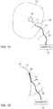
- FIG. 7A depicts one embodiment of how the catheters described herein may be implemented.
- the catheter 700 is used to perform epicardial ablation.
- Line 702 represents the entry point of a human body.
- an entry point 706 is created in the pericardium by slitting the pericardium to enable the electrode-equipped distal portion 708 of the catheter 700 to be positioned against the epicardial surface. Since the distal portion 708 of the catheter is configured in a plane that is parallel to a longitudinal axis of the catheter 700 (at least the portion of the catheter 710 near the distal portion 708), the planar distal portion 708 may be moved along the epicardial surface to a target ablation site by moving under the pericardium.
- the distal portion 708 is shown below the pericardium 712 and the epicardial surface 714.
- the electrodes (not shown) at the distal portion 708 may be energized by, for example, the generator 716 to pass current through the electrodes and into the proximate tissue.
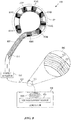
- FIG. 8 is a representative example of a system including a catheter 800 having a shaft 802, and a shaft extension 804 with a plurality of electrodes 806A-H arranged beyond the end of the shaft 802 and in a plane substantially aligned with the shaft 802 axis.
- the system further includes a handle 820 and a generator 830.
- the generator 830 represents a DC and/or AC voltage generator 832 that can generate one or more pulses of energy or "shocks.”
- the voltage generator 832 can perform analogously to a defibrillator, where a monophasic or biphasic pulse or series of pulses of energy can be delivered.
- the voltage generator 832 provides energy to each of the conductors 810 that respectively connect to the electrodes 806A-H.
- a cable(s) 822 can be coupled between a connector 834 of the generator 830 and the handle 820.
- a breakout view 840 of a portion of such a cable 822 is depicted, where the cable 822 includes conductors 835 from the generator that are respectively coupled to the conductors 812 at the handle/actuator 820 (connections not shown).
- the handle 820 may include a connector capable of receiving the conductors 836, and capable of receiving the conductors 810, where the conductors 836 are connected one-to-one to conductors 810, thereby providing energy from the generator 830 to each of the electrodes 806A-H.
- current is sourced from the generator 830, and passed from one or more of the electrodes 804A-H, and returned via a return path.
- the return path may be provided via a body patch, another catheter in the area, an electrode on an introducer/sheath, etc.
- FIG. 9A is a flow diagram of one representative manner for creating an ablation catheter.
- electrodes are positioned 900 on a distal portion of an ablation catheter.
- the distal portion is configured 902 into a planar shape, and the plane of the planar shape is aligned 904 with the longitudinal axis of the catheter shaft.
- the plurality of electrodes does not create an angle relative to shaft, to facilitate particular uses of the catheter.
- FIG. 9B is a flow diagram of another representative manner for creating an ablation catheter.
- the electrodes are positioned 910 on a distal portion of an irreversible electroporation (IRE) ablation catheter.
- the distal portion is configured 912 into a circular shape using, for example, memory wire such as nitinol.
- a conductor is respectively coupled 914 to each of the electrodes, and each of the conductors is coupled 916 to a generator connector(s) at a catheter handle.
- One or more deflection tethers e.g. wires
- the plane of the circular-shaped electrode plane is aligned 920 with the longitudinal axis of the catheter shaft. In this manner, the plurality of electrodes does not create an angle relative to shaft, to facilitate particular uses of the catheter.
Landscapes
- Health & Medical Sciences (AREA)
- Life Sciences & Earth Sciences (AREA)
- Engineering & Computer Science (AREA)
- Surgery (AREA)
- Public Health (AREA)
- Biomedical Technology (AREA)
- Veterinary Medicine (AREA)
- Animal Behavior & Ethology (AREA)
- General Health & Medical Sciences (AREA)
- Heart & Thoracic Surgery (AREA)
- Molecular Biology (AREA)
- Nuclear Medicine, Radiotherapy & Molecular Imaging (AREA)
- Medical Informatics (AREA)
- Physics & Mathematics (AREA)
- Plasma & Fusion (AREA)
- Otolaryngology (AREA)
- Hematology (AREA)
- Anesthesiology (AREA)
- Mechanical Engineering (AREA)
- Biophysics (AREA)
- Pulmonology (AREA)
- Cardiology (AREA)
- Radiology & Medical Imaging (AREA)
- Surgical Instruments (AREA)
- Measurement And Recording Of Electrical Phenomena And Electrical Characteristics Of The Living Body (AREA)
Claims (8)
- Cathéter comprenant :une tige (102 ; 202 ; 302 ; 502 ; 802) ; etun segment distal (104 ; 204 ; 304 ; 504 ; 804) de la tige ayant une pluralité d'électrodes (106 ; 206A à H ; 306 ; 806A à H), dans lequel le segment distal et la pluralité d'électrodes sont configurés dans un plan qui est sensiblement parallèle à l'axe longitudinal de la tige, etdans lequel la pluralité d'électrodes est configurée pour s'adapter à des courants continus (CC) aptes à une électroporation irréversible de cellules dans un tissu organique,caractérisé en ce quele segment distal de la tige s'écarte d'un chemin droit et est configuré à l'aide d'un fil à mémoire selon une forme plane, eten ce que la forme est flexible, et après élimination d'une force amenant la forme à fléchir, retourne à la forme plane déterminée par le fil à mémoire.
- Cathéter selon la revendication 1, comprenant en outre une pluralité de conducteurs (810), un pour chacune de la pluralité d'électrodes, à travers lesquels le courant peut passer pour alimenter en énergie les électrodes respectives de la pluralité d'électrodes.
- Cathéter selon la revendication 1 ou 2, dans lequel le segment distal (204 ; 304) de la tige (202 ; 302) est configuré selon une forme circulaire.
- Cathéter selon la revendication 1, comprenant en outre :un segment pouvant être défléchi (524 ; 612A) de la tige qui comporte le segment distal (504 ; 804) de la tige ;une première attache de déflexion manipulable couplée au segment pouvant être défléchi ; etdans lequel l'augmentation de la tension sur la première attache de déflexion manipulable amène le segment pouvant être défléchi de la tige (502 ; 802) à se défléchir dans une première direction.
- Cathéter selon la revendication 4, comprenant en outre une deuxième attache de déflexion manipulable couplée au segment pouvant être défléchi à l'opposé du couplage de la première attache de déflexion manipulable, dans lequel l'augmentation de la tension sur la première attache de déflexion manipulable amène le segment pouvant être défléchi de la tige (802) à se défléchir dans une deuxième direction.
- Cathéter selon la revendication 5, comprenant en outre une nième attache de déflexion manipulable couplée au segment pouvant être défléchi entre d'autres attaches de déflexion manipulables, dans lequel l'augmentation de la tension sur la nième attache de déflexion manipulable amène le segment pouvant être défléchi de la tige (802) à se défléchir dans une nième direction.
- Système comprenant :un cathéter (800) de l'une quelconque des revendications 1 à 6,une source de tension (832) continue (CC), etau moins un câble (822) couplé entre la source de tension continue et la pluralité d'électrodes sur le cathéter (800).
- Système selon la revendication 7, comprenant en outre un introducteur médical configuré pour faire passer le cathéter (800) au travers une cible d'ablation.
Applications Claiming Priority (2)
| Application Number | Priority Date | Filing Date | Title |
|---|---|---|---|
| US201461938417P | 2014-02-11 | 2014-02-11 | |
| PCT/US2015/015116 WO2015123163A1 (fr) | 2014-02-11 | 2015-02-10 | Cathéter d'ablation et procédés associés |
Publications (2)
| Publication Number | Publication Date |
|---|---|
| EP3089687A1 EP3089687A1 (fr) | 2016-11-09 |
| EP3089687B1 true EP3089687B1 (fr) | 2018-06-06 |
Family
ID=52472646
Family Applications (1)
| Application Number | Title | Priority Date | Filing Date |
|---|---|---|---|
| EP15704691.3A Active EP3089687B1 (fr) | 2014-02-11 | 2015-02-10 | Cathéter d'ablation |
Country Status (5)
| Country | Link |
|---|---|
| US (3) | US20170172654A1 (fr) |
| EP (1) | EP3089687B1 (fr) |
| JP (1) | JP6779133B2 (fr) |
| CN (1) | CN105979896A (fr) |
| WO (1) | WO2015123163A1 (fr) |
Cited By (3)
| Publication number | Priority date | Publication date | Assignee | Title |
|---|---|---|---|---|
| US11786300B2 (en) | 2021-04-07 | 2023-10-17 | Btl Medical Technologies S.R.O. | Pulsed field ablation device and method |
| US11896298B2 (en) | 2021-07-06 | 2024-02-13 | Btl Medical Development A.S. | Pulsed field ablation device and method |
| US12076067B2 (en) | 2022-10-05 | 2024-09-03 | Btl Medical Development A.S. | Pulsed field ablation device and method |
Families Citing this family (41)
| Publication number | Priority date | Publication date | Assignee | Title |
|---|---|---|---|---|
| WO2014025394A1 (fr) | 2012-08-09 | 2014-02-13 | University Of Iowa Research Foundation | Cathéters, systèmes de cathéter et procédés de perforation à travers une structure de tissu |
| EP3091921B1 (fr) | 2014-01-06 | 2019-06-19 | Farapulse, Inc. | Appareil pour ablation de dénervation rénale |
| EP3495018B1 (fr) | 2014-05-07 | 2023-09-06 | Farapulse, Inc. | Appareil d'ablation de tissus sélectifs |
| EP3142584A1 (fr) | 2014-05-16 | 2017-03-22 | Iowa Approach Inc. | Méthodes et appareil d'ablation tissulaire à plusieurs cathéters |
| EP4559428A3 (fr) | 2014-06-12 | 2025-08-20 | Boston Scientific Scimed, Inc. | Procede et appareil d'ablation tissulaire rapide et selective avec refroidissement |
| WO2015192027A1 (fr) | 2014-06-12 | 2015-12-17 | Iowa Approach Inc. | Procédé et appareil d'ablation transurétrale de tissu rapide et sélective |
| EP3206613B1 (fr) | 2014-10-14 | 2019-07-03 | Farapulse, Inc. | Appareil pour l'ablation rapide et sûre d'une veine cardiopulmonaire |
| US10130423B1 (en) | 2017-07-06 | 2018-11-20 | Farapulse, Inc. | Systems, devices, and methods for focal ablation |
| US12144541B2 (en) | 2016-01-05 | 2024-11-19 | Boston Scientific Scimed, Inc. | Systems, apparatuses and methods for delivery of ablative energy to tissue |
| US10172673B2 (en) | 2016-01-05 | 2019-01-08 | Farapulse, Inc. | Systems devices, and methods for delivery of pulsed electric field ablative energy to endocardial tissue |
| US20170189097A1 (en) | 2016-01-05 | 2017-07-06 | Iowa Approach Inc. | Systems, apparatuses and methods for delivery of ablative energy to tissue |
| US10660702B2 (en) | 2016-01-05 | 2020-05-26 | Farapulse, Inc. | Systems, devices, and methods for focal ablation |
| WO2017218734A1 (fr) | 2016-06-16 | 2017-12-21 | Iowa Approach, Inc. | Systèmes, appareils et procédés de distribution de fil de guidage |
| CA3048487A1 (fr) * | 2017-03-07 | 2018-09-13 | Boston Scientific Scimed, Inc. | Dispositif d'acces endoscopique guide par ultrasons |
| US9987081B1 (en) | 2017-04-27 | 2018-06-05 | Iowa Approach, Inc. | Systems, devices, and methods for signal generation |
| US10617867B2 (en) | 2017-04-28 | 2020-04-14 | Farapulse, Inc. | Systems, devices, and methods for delivery of pulsed electric field ablative energy to esophageal tissue |
| JP7586706B2 (ja) | 2017-09-12 | 2024-11-19 | ボストン サイエンティフィック サイムド,インコーポレイテッド | 心室フォーカルアブレーションのためのシステム、装置、及び方法 |
| EP3459480A1 (fr) * | 2017-09-21 | 2019-03-27 | National University of Ireland, Galway | Appareil permettant de localiser un champ électrique |
| CN107598506B (zh) * | 2017-10-27 | 2019-11-29 | 深圳华讯角度生物医疗电子科技有限公司 | 高频手术电极刀头生产工艺 |
| CN118634408A (zh) * | 2018-01-02 | 2024-09-13 | 圣犹达医疗用品心脏病学部门有限公司 | 包括远侧环的电穿孔导管 |
| WO2019157359A1 (fr) | 2018-02-08 | 2019-08-15 | Farapulse, Inc. | Procédé et appareil d'application contrôlée d'une énergie d'ablation à champ électrique pulsé sur un tissu |
| US12383331B2 (en) | 2018-03-06 | 2025-08-12 | St. Jude Medical, Cardiology Division, Inc. | Systems and methods for limiting arcing in electroporation systems |
| US20190336198A1 (en) | 2018-05-03 | 2019-11-07 | Farapulse, Inc. | Systems, devices, and methods for ablation using surgical clamps |
| CN116327352A (zh) | 2018-05-07 | 2023-06-27 | 波士顿科学医学有限公司 | 心外膜消融导管 |
| WO2019217317A1 (fr) | 2018-05-07 | 2019-11-14 | Farapulse, Inc. | Systèmes, appareils et procédés pour filtrer un bruit haute tension induit par une ablation par champ électrique pulsé |
| CN115836908A (zh) | 2018-05-07 | 2023-03-24 | 波士顿科学医学有限公司 | 用于将消融能量递送到组织的系统、设备和方法 |
| JP7619937B2 (ja) | 2018-09-20 | 2025-01-22 | ボストン サイエンティフィック サイムド,インコーポレイテッド | 心内膜組織へのパルス電界アブレーションエネルギーの送達のためのシステム、装置、および方法 |
| CN110279464A (zh) * | 2019-06-27 | 2019-09-27 | 深圳市惠泰医疗器械有限公司 | 带环状柔性头端的肾动脉多极刺激消融电极导管 |
| US10625080B1 (en) | 2019-09-17 | 2020-04-21 | Farapulse, Inc. | Systems, apparatuses, and methods for detecting ectopic electrocardiogram signals during pulsed electric field ablation |
| US11065047B2 (en) | 2019-11-20 | 2021-07-20 | Farapulse, Inc. | Systems, apparatuses, and methods for protecting electronic components from high power noise induced by high voltage pulses |
| US11497541B2 (en) | 2019-11-20 | 2022-11-15 | Boston Scientific Scimed, Inc. | Systems, apparatuses, and methods for protecting electronic components from high power noise induced by high voltage pulses |
| US10842572B1 (en) | 2019-11-25 | 2020-11-24 | Farapulse, Inc. | Methods, systems, and apparatuses for tracking ablation devices and generating lesion lines |
| JP7459252B2 (ja) * | 2019-12-03 | 2024-04-01 | セント・ジュード・メディカル,カーディオロジー・ディヴィジョン,インコーポレイテッド | 電気穿孔システムおよび方法 |
| DE21701063T1 (de) * | 2020-01-13 | 2023-03-23 | Medlumics S.L. | Optisch geführtes ablationssystem zur verwendung mit gepulster feldenergiequelle |
| WO2021257397A1 (fr) * | 2020-06-18 | 2021-12-23 | St. Jude Medical, Cardiology Division, Inc. | Dispositif et procédé d'administration de thérapie d'électroporation |
| JP7536995B2 (ja) | 2020-07-24 | 2024-08-20 | ボストン サイエンティフィック サイムド,インコーポレイテッド | 不可逆電気穿孔によるシングル・ショット心臓アブレーションのための電界印加 |
| US12310652B2 (en) | 2020-07-24 | 2025-05-27 | Boston Scientific Scimed, Inc. | Hybrid electroporation ablation catheter |
| US12076071B2 (en) | 2020-08-14 | 2024-09-03 | Kardium Inc. | Systems and methods for treating tissue with pulsed field ablation |
| CN116157085A (zh) | 2020-09-08 | 2023-05-23 | 波士顿科学医学有限公司 | 用于脉冲电场消融的波浪形电极及其系统、设备和方法 |
| JP7564353B2 (ja) | 2020-09-30 | 2024-10-08 | ボストン サイエンティフィック サイムド,インコーポレイテッド | 不可逆的電気穿孔のための前処理波形 |
| CN116744870A (zh) | 2021-01-27 | 2023-09-12 | 波士顿科学医学有限公司 | 用于不可逆电穿孔消融的电压控制的脉冲序列 |
Family Cites Families (16)
| Publication number | Priority date | Publication date | Assignee | Title |
|---|---|---|---|---|
| US5454370A (en) * | 1993-12-03 | 1995-10-03 | Avitall; Boaz | Mapping and ablation electrode configuration |
| US6048329A (en) * | 1996-12-19 | 2000-04-11 | Ep Technologies, Inc. | Catheter distal assembly with pull wires |
| DE60211896T2 (de) * | 2001-05-21 | 2007-05-10 | Medtronic, Inc., Minneapolis | Verformbare langgestreckte medizinische vorrichtung |
| US7013169B2 (en) * | 2003-01-27 | 2006-03-14 | Cardiac Pacemakers, Inc. | Dual steer preshaped catheter |
| US20050059963A1 (en) * | 2003-09-12 | 2005-03-17 | Scimed Life Systems, Inc. | Systems and method for creating transmural lesions |
| US7238179B2 (en) * | 2003-10-30 | 2007-07-03 | Medical Cv, Inc. | Apparatus and method for guided ablation treatment |
| US20050261672A1 (en) * | 2004-05-18 | 2005-11-24 | Mark Deem | Systems and methods for selective denervation of heart dysrhythmias |
| CA2586022A1 (fr) * | 2004-10-28 | 2006-05-11 | Medicalcv, Inc. | Appareil et procede de traitement par ablation guidee |
| WO2007005641A2 (fr) * | 2005-07-01 | 2007-01-11 | Proteus Biomedical, Inc. | Ensemble d'electrodes et de capteurs epicardique deployable |
| US20070156135A1 (en) * | 2006-01-03 | 2007-07-05 | Boris Rubinsky | System and methods for treating atrial fibrillation using electroporation |
| US8287532B2 (en) * | 2009-04-13 | 2012-10-16 | Biosense Webster, Inc. | Epicardial mapping and ablation catheter |
| WO2011075328A1 (fr) * | 2009-12-14 | 2011-06-23 | Mayo Foundation For Medical Education And Research | Dispositif et procédé de traitement des troubles cardiaques par modulation d'une réponse autonome |
| WO2011122488A1 (fr) * | 2010-03-29 | 2011-10-06 | テルモ株式会社 | Ensemble gaine d'introducteur |
| WO2012068505A1 (fr) * | 2010-11-19 | 2012-05-24 | St. Jude Medical, Atrial Fibrillation Division, Inc. | Dispositif de cathéter à électrode comportant une électrode indifférente pour thérapies tissulaires par courant continu |
| US9233241B2 (en) * | 2011-02-28 | 2016-01-12 | Ethicon Endo-Surgery, Inc. | Electrical ablation devices and methods |
| US10314649B2 (en) * | 2012-08-02 | 2019-06-11 | Ethicon Endo-Surgery, Inc. | Flexible expandable electrode and method of intraluminal delivery of pulsed power |
-
2015
- 2015-02-10 EP EP15704691.3A patent/EP3089687B1/fr active Active
- 2015-02-10 WO PCT/US2015/015116 patent/WO2015123163A1/fr not_active Ceased
- 2015-02-10 JP JP2016550247A patent/JP6779133B2/ja active Active
- 2015-02-10 CN CN201580007211.0A patent/CN105979896A/zh active Pending
- 2015-02-10 US US15/116,308 patent/US20170172654A1/en not_active Abandoned
-
2019
- 2019-12-17 US US16/716,596 patent/US20200179046A1/en not_active Abandoned
-
2023
- 2023-12-29 US US18/400,577 patent/US20240197390A1/en not_active Abandoned
Non-Patent Citations (1)
| Title |
|---|
| None * |
Cited By (5)
| Publication number | Priority date | Publication date | Assignee | Title |
|---|---|---|---|---|
| US11786300B2 (en) | 2021-04-07 | 2023-10-17 | Btl Medical Technologies S.R.O. | Pulsed field ablation device and method |
| US11832785B2 (en) | 2021-04-07 | 2023-12-05 | Btl Medical Development A.S. | Pulsed field ablation device and method |
| US11896298B2 (en) | 2021-07-06 | 2024-02-13 | Btl Medical Development A.S. | Pulsed field ablation device and method |
| US12076067B2 (en) | 2022-10-05 | 2024-09-03 | Btl Medical Development A.S. | Pulsed field ablation device and method |
| US12279801B2 (en) | 2022-10-05 | 2025-04-22 | Btl Medical Development A.S. | Pulsed field ablation device and method |
Also Published As
| Publication number | Publication date |
|---|---|
| JP2017506098A (ja) | 2017-03-02 |
| CN105979896A (zh) | 2016-09-28 |
| US20200179046A1 (en) | 2020-06-11 |
| WO2015123163A1 (fr) | 2015-08-20 |
| EP3089687A1 (fr) | 2016-11-09 |
| JP6779133B2 (ja) | 2020-11-04 |
| US20240197390A1 (en) | 2024-06-20 |
| US20170172654A1 (en) | 2017-06-22 |
Similar Documents
| Publication | Publication Date | Title |
|---|---|---|
| US20240197390A1 (en) | Ablation catheter and associated methods | |
| US20260007464A1 (en) | Ablation catheter and method for electrically isolating cardiac tissue | |
| US20250177041A1 (en) | Oriented irreversible-electroporation (ire) pulses to compensate for cell size and orientation | |
| US9999465B2 (en) | Method and apparatus for rapid and safe pulmonary vein cardiac ablation | |
| US20130338467A1 (en) | Electrode catheter device with indifferent electrode for direct current tissue therapies | |
| KR20220008205A (ko) | 비가역적 전기천공(ire) 동안 전극 쌍들의 순차적 활성화 | |
| EP4215144A1 (fr) | Ensembles d'électrodes d'un cathéter à panier ayant des éléments de retenue mécaniques et procédés associés | |
| US20230225787A1 (en) | Systems and methods for linear spines forming a spherical basket for improved tissue contact and current delivery | |
| EP4193947A1 (fr) | Cathéter panier avec des colonnes reliées électriquement formant une électrode distribuée | |
| EP4215142B1 (fr) | Systèmes et procédés pour des rameaux tripodes formant un panier sphérique pour un contact amélioré avec un tissu et une distribution de courant améliorée | |
| US12446946B2 (en) | Systems and methods for a single spiral electrode assembly forming a spherical basket for improved tissue contact and current delivery | |
| US20250295448A1 (en) | Mapping and ablation system suitable for linear pulsed-field cardiac ablation | |
| US20240197392A1 (en) | Multi-electrode basket end effector of a catheter | |
| US12521035B2 (en) | Cylindrical cage systems and methods for distributed tissue contact for mapping and ablation | |
| EP4378408A2 (fr) | Ensemble panier, dos et électrodes pour cathéter | |
| US12629203B2 (en) | Elongated trapezoidal electrodes of a basket catheter and methods of making the same | |
| JP6113780B2 (ja) | アブレーションカテーテル及び心臓組織を電気的に絶縁するための方法 | |
| EP4268749A1 (fr) | Systèmes et dispositifs pour un écoulement d'irrigation amélioré pendant une procédure cardiaque | |
| US20230301712A1 (en) | Elongated trapezoidal electrodes of a basket catheter and methods of making the same | |
| US20240374304A1 (en) | Electrical connector for a catheter device | |
| US20240216046A1 (en) | Systems and methods for linear spines forming a spherical basket for improved tissue contact and current delivery |
Legal Events
| Date | Code | Title | Description |
|---|---|---|---|
| PUAI | Public reference made under article 153(3) epc to a published international application that has entered the european phase |
Free format text: ORIGINAL CODE: 0009012 |
|
| 17P | Request for examination filed |
Effective date: 20160801 |
|
| AK | Designated contracting states |
Kind code of ref document: A1 Designated state(s): AL AT BE BG CH CY CZ DE DK EE ES FI FR GB GR HR HU IE IS IT LI LT LU LV MC MK MT NL NO PL PT RO RS SE SI SK SM TR |
|
| AX | Request for extension of the european patent |
Extension state: BA ME |
|
| DAX | Request for extension of the european patent (deleted) | ||
| STAA | Information on the status of an ep patent application or granted ep patent |
Free format text: STATUS: EXAMINATION IS IN PROGRESS |
|
| 17Q | First examination report despatched |
Effective date: 20170710 |
|
| GRAP | Despatch of communication of intention to grant a patent |
Free format text: ORIGINAL CODE: EPIDOSNIGR1 |
|
| STAA | Information on the status of an ep patent application or granted ep patent |
Free format text: STATUS: GRANT OF PATENT IS INTENDED |
|
| INTG | Intention to grant announced |
Effective date: 20180220 |
|
| RIN1 | Information on inventor provided before grant (corrected) |
Inventor name: MONAHAN, BRIAN Inventor name: WITTKAMPF, FREDERIK H.M. |
|
| GRAS | Grant fee paid |
Free format text: ORIGINAL CODE: EPIDOSNIGR3 |
|
| GRAA | (expected) grant |
Free format text: ORIGINAL CODE: 0009210 |
|
| STAA | Information on the status of an ep patent application or granted ep patent |
Free format text: STATUS: THE PATENT HAS BEEN GRANTED |
|
| AK | Designated contracting states |
Kind code of ref document: B1 Designated state(s): AL AT BE BG CH CY CZ DE DK EE ES FI FR GB GR HR HU IE IS IT LI LT LU LV MC MK MT NL NO PL PT RO RS SE SI SK SM TR |
|
| REG | Reference to a national code |
Ref country code: GB Ref legal event code: FG4D |
|
| REG | Reference to a national code |
Ref country code: CH Ref legal event code: EP Ref country code: AT Ref legal event code: REF Ref document number: 1005195 Country of ref document: AT Kind code of ref document: T Effective date: 20180615 |
|
| REG | Reference to a national code |
Ref country code: IE Ref legal event code: FG4D |
|
| REG | Reference to a national code |
Ref country code: DE Ref legal event code: R096 Ref document number: 602015011798 Country of ref document: DE |
|
| REG | Reference to a national code |
Ref country code: NL Ref legal event code: MP Effective date: 20180606 |
|
| REG | Reference to a national code |
Ref country code: LT Ref legal event code: MG4D |
|
| PG25 | Lapsed in a contracting state [announced via postgrant information from national office to epo] |
Ref country code: SE Free format text: LAPSE BECAUSE OF FAILURE TO SUBMIT A TRANSLATION OF THE DESCRIPTION OR TO PAY THE FEE WITHIN THE PRESCRIBED TIME-LIMIT Effective date: 20180606 Ref country code: FI Free format text: LAPSE BECAUSE OF FAILURE TO SUBMIT A TRANSLATION OF THE DESCRIPTION OR TO PAY THE FEE WITHIN THE PRESCRIBED TIME-LIMIT Effective date: 20180606 Ref country code: BG Free format text: LAPSE BECAUSE OF FAILURE TO SUBMIT A TRANSLATION OF THE DESCRIPTION OR TO PAY THE FEE WITHIN THE PRESCRIBED TIME-LIMIT Effective date: 20180906 Ref country code: NO Free format text: LAPSE BECAUSE OF FAILURE TO SUBMIT A TRANSLATION OF THE DESCRIPTION OR TO PAY THE FEE WITHIN THE PRESCRIBED TIME-LIMIT Effective date: 20180906 Ref country code: CY Free format text: LAPSE BECAUSE OF FAILURE TO SUBMIT A TRANSLATION OF THE DESCRIPTION OR TO PAY THE FEE WITHIN THE PRESCRIBED TIME-LIMIT Effective date: 20180606 Ref country code: LT Free format text: LAPSE BECAUSE OF FAILURE TO SUBMIT A TRANSLATION OF THE DESCRIPTION OR TO PAY THE FEE WITHIN THE PRESCRIBED TIME-LIMIT Effective date: 20180606 Ref country code: ES Free format text: LAPSE BECAUSE OF FAILURE TO SUBMIT A TRANSLATION OF THE DESCRIPTION OR TO PAY THE FEE WITHIN THE PRESCRIBED TIME-LIMIT Effective date: 20180606 |
|
| PG25 | Lapsed in a contracting state [announced via postgrant information from national office to epo] |
Ref country code: GR Free format text: LAPSE BECAUSE OF FAILURE TO SUBMIT A TRANSLATION OF THE DESCRIPTION OR TO PAY THE FEE WITHIN THE PRESCRIBED TIME-LIMIT Effective date: 20180907 Ref country code: HR Free format text: LAPSE BECAUSE OF FAILURE TO SUBMIT A TRANSLATION OF THE DESCRIPTION OR TO PAY THE FEE WITHIN THE PRESCRIBED TIME-LIMIT Effective date: 20180606 Ref country code: LV Free format text: LAPSE BECAUSE OF FAILURE TO SUBMIT A TRANSLATION OF THE DESCRIPTION OR TO PAY THE FEE WITHIN THE PRESCRIBED TIME-LIMIT Effective date: 20180606 Ref country code: RS Free format text: LAPSE BECAUSE OF FAILURE TO SUBMIT A TRANSLATION OF THE DESCRIPTION OR TO PAY THE FEE WITHIN THE PRESCRIBED TIME-LIMIT Effective date: 20180606 |
|
| REG | Reference to a national code |
Ref country code: AT Ref legal event code: MK05 Ref document number: 1005195 Country of ref document: AT Kind code of ref document: T Effective date: 20180606 |
|
| PG25 | Lapsed in a contracting state [announced via postgrant information from national office to epo] |
Ref country code: NL Free format text: LAPSE BECAUSE OF FAILURE TO SUBMIT A TRANSLATION OF THE DESCRIPTION OR TO PAY THE FEE WITHIN THE PRESCRIBED TIME-LIMIT Effective date: 20180606 |
|
| PG25 | Lapsed in a contracting state [announced via postgrant information from national office to epo] |
Ref country code: CZ Free format text: LAPSE BECAUSE OF FAILURE TO SUBMIT A TRANSLATION OF THE DESCRIPTION OR TO PAY THE FEE WITHIN THE PRESCRIBED TIME-LIMIT Effective date: 20180606 Ref country code: RO Free format text: LAPSE BECAUSE OF FAILURE TO SUBMIT A TRANSLATION OF THE DESCRIPTION OR TO PAY THE FEE WITHIN THE PRESCRIBED TIME-LIMIT Effective date: 20180606 Ref country code: PL Free format text: LAPSE BECAUSE OF FAILURE TO SUBMIT A TRANSLATION OF THE DESCRIPTION OR TO PAY THE FEE WITHIN THE PRESCRIBED TIME-LIMIT Effective date: 20180606 Ref country code: IS Free format text: LAPSE BECAUSE OF FAILURE TO SUBMIT A TRANSLATION OF THE DESCRIPTION OR TO PAY THE FEE WITHIN THE PRESCRIBED TIME-LIMIT Effective date: 20181006 Ref country code: EE Free format text: LAPSE BECAUSE OF FAILURE TO SUBMIT A TRANSLATION OF THE DESCRIPTION OR TO PAY THE FEE WITHIN THE PRESCRIBED TIME-LIMIT Effective date: 20180606 Ref country code: AT Free format text: LAPSE BECAUSE OF FAILURE TO SUBMIT A TRANSLATION OF THE DESCRIPTION OR TO PAY THE FEE WITHIN THE PRESCRIBED TIME-LIMIT Effective date: 20180606 Ref country code: SK Free format text: LAPSE BECAUSE OF FAILURE TO SUBMIT A TRANSLATION OF THE DESCRIPTION OR TO PAY THE FEE WITHIN THE PRESCRIBED TIME-LIMIT Effective date: 20180606 |
|
| PG25 | Lapsed in a contracting state [announced via postgrant information from national office to epo] |
Ref country code: SM Free format text: LAPSE BECAUSE OF FAILURE TO SUBMIT A TRANSLATION OF THE DESCRIPTION OR TO PAY THE FEE WITHIN THE PRESCRIBED TIME-LIMIT Effective date: 20180606 |
|
| REG | Reference to a national code |
Ref country code: DE Ref legal event code: R097 Ref document number: 602015011798 Country of ref document: DE |
|
| PLBE | No opposition filed within time limit |
Free format text: ORIGINAL CODE: 0009261 |
|
| STAA | Information on the status of an ep patent application or granted ep patent |
Free format text: STATUS: NO OPPOSITION FILED WITHIN TIME LIMIT |
|
| 26N | No opposition filed |
Effective date: 20190307 |
|
| PG25 | Lapsed in a contracting state [announced via postgrant information from national office to epo] |
Ref country code: SI Free format text: LAPSE BECAUSE OF FAILURE TO SUBMIT A TRANSLATION OF THE DESCRIPTION OR TO PAY THE FEE WITHIN THE PRESCRIBED TIME-LIMIT Effective date: 20180606 Ref country code: DK Free format text: LAPSE BECAUSE OF FAILURE TO SUBMIT A TRANSLATION OF THE DESCRIPTION OR TO PAY THE FEE WITHIN THE PRESCRIBED TIME-LIMIT Effective date: 20180606 |
|
| REG | Reference to a national code |
Ref country code: CH Ref legal event code: PL |
|
| PG25 | Lapsed in a contracting state [announced via postgrant information from national office to epo] |
Ref country code: MC Free format text: LAPSE BECAUSE OF FAILURE TO SUBMIT A TRANSLATION OF THE DESCRIPTION OR TO PAY THE FEE WITHIN THE PRESCRIBED TIME-LIMIT Effective date: 20180606 Ref country code: LU Free format text: LAPSE BECAUSE OF NON-PAYMENT OF DUE FEES Effective date: 20190210 |
|
| REG | Reference to a national code |
Ref country code: BE Ref legal event code: MM Effective date: 20190228 |
|
| REG | Reference to a national code |
Ref country code: IE Ref legal event code: MM4A |
|
| PG25 | Lapsed in a contracting state [announced via postgrant information from national office to epo] |
Ref country code: AL Free format text: LAPSE BECAUSE OF FAILURE TO SUBMIT A TRANSLATION OF THE DESCRIPTION OR TO PAY THE FEE WITHIN THE PRESCRIBED TIME-LIMIT Effective date: 20180606 |
|
| PG25 | Lapsed in a contracting state [announced via postgrant information from national office to epo] |
Ref country code: CH Free format text: LAPSE BECAUSE OF NON-PAYMENT OF DUE FEES Effective date: 20190228 Ref country code: LI Free format text: LAPSE BECAUSE OF NON-PAYMENT OF DUE FEES Effective date: 20190228 |
|
| PG25 | Lapsed in a contracting state [announced via postgrant information from national office to epo] |
Ref country code: IE Free format text: LAPSE BECAUSE OF NON-PAYMENT OF DUE FEES Effective date: 20190210 |
|
| PG25 | Lapsed in a contracting state [announced via postgrant information from national office to epo] |
Ref country code: BE Free format text: LAPSE BECAUSE OF NON-PAYMENT OF DUE FEES Effective date: 20190228 |
|
| PG25 | Lapsed in a contracting state [announced via postgrant information from national office to epo] |
Ref country code: TR Free format text: LAPSE BECAUSE OF FAILURE TO SUBMIT A TRANSLATION OF THE DESCRIPTION OR TO PAY THE FEE WITHIN THE PRESCRIBED TIME-LIMIT Effective date: 20180606 |
|
| PG25 | Lapsed in a contracting state [announced via postgrant information from national office to epo] |
Ref country code: PT Free format text: LAPSE BECAUSE OF FAILURE TO SUBMIT A TRANSLATION OF THE DESCRIPTION OR TO PAY THE FEE WITHIN THE PRESCRIBED TIME-LIMIT Effective date: 20181008 Ref country code: MT Free format text: LAPSE BECAUSE OF NON-PAYMENT OF DUE FEES Effective date: 20190210 |
|
| PG25 | Lapsed in a contracting state [announced via postgrant information from national office to epo] |
Ref country code: HU Free format text: LAPSE BECAUSE OF FAILURE TO SUBMIT A TRANSLATION OF THE DESCRIPTION OR TO PAY THE FEE WITHIN THE PRESCRIBED TIME-LIMIT; INVALID AB INITIO Effective date: 20150210 |
|
| PG25 | Lapsed in a contracting state [announced via postgrant information from national office to epo] |
Ref country code: MK Free format text: LAPSE BECAUSE OF FAILURE TO SUBMIT A TRANSLATION OF THE DESCRIPTION OR TO PAY THE FEE WITHIN THE PRESCRIBED TIME-LIMIT Effective date: 20180606 |
|
| P01 | Opt-out of the competence of the unified patent court (upc) registered |
Effective date: 20230616 |
|
| REG | Reference to a national code |
Ref country code: DE Ref legal event code: R082 Ref document number: 602015011798 Country of ref document: DE Representative=s name: ALPSPITZ IP ALLGAYER UND PARTNER PATENTANWAELT, DE |
|
| PGFP | Annual fee paid to national office [announced via postgrant information from national office to epo] |
Ref country code: GB Payment date: 20260113 Year of fee payment: 12 |
|
| PGFP | Annual fee paid to national office [announced via postgrant information from national office to epo] |
Ref country code: DE Payment date: 20260115 Year of fee payment: 12 |
|
| PGFP | Annual fee paid to national office [announced via postgrant information from national office to epo] |
Ref country code: IT Payment date: 20260212 Year of fee payment: 12 |
|
| PGFP | Annual fee paid to national office [announced via postgrant information from national office to epo] |
Ref country code: FR Payment date: 20260109 Year of fee payment: 12 |