EP3090953A1 - Station de coupe pour une machine d'emballage en bande - Google Patents
Station de coupe pour une machine d'emballage en bande Download PDFInfo
- Publication number
- EP3090953A1 EP3090953A1 EP16000932.0A EP16000932A EP3090953A1 EP 3090953 A1 EP3090953 A1 EP 3090953A1 EP 16000932 A EP16000932 A EP 16000932A EP 3090953 A1 EP3090953 A1 EP 3090953A1
- Authority
- EP
- European Patent Office
- Prior art keywords
- clamping plate
- cutting
- sealed packages
- cutting station
- lower clamping
- Prior art date
- Legal status (The legal status is an assumption and is not a legal conclusion. Google has not performed a legal analysis and makes no representation as to the accuracy of the status listed.)
- Granted
Links
Images







Classifications
-
- B—PERFORMING OPERATIONS; TRANSPORTING
- B26—HAND CUTTING TOOLS; CUTTING; SEVERING
- B26D—CUTTING; DETAILS COMMON TO MACHINES FOR PERFORATING, PUNCHING, CUTTING-OUT, STAMPING-OUT OR SEVERING
- B26D5/00—Arrangements for operating and controlling machines or devices for cutting, cutting-out, stamping-out, punching, perforating, or severing by means other than cutting
- B26D5/08—Means for actuating the cutting member to effect the cut
-
- B—PERFORMING OPERATIONS; TRANSPORTING
- B65—CONVEYING; PACKING; STORING; HANDLING THIN OR FILAMENTARY MATERIAL
- B65B—MACHINES, APPARATUS OR DEVICES FOR, OR METHODS OF, PACKAGING ARTICLES OR MATERIALS; UNPACKING
- B65B61/00—Auxiliary devices, not otherwise provided for, for operating on sheets, blanks, webs, binding material, containers or packages
- B65B61/04—Auxiliary devices, not otherwise provided for, for operating on sheets, blanks, webs, binding material, containers or packages for severing webs, or for separating joined packages
- B65B61/06—Auxiliary devices, not otherwise provided for, for operating on sheets, blanks, webs, binding material, containers or packages for severing webs, or for separating joined packages by cutting
-
- B—PERFORMING OPERATIONS; TRANSPORTING
- B26—HAND CUTTING TOOLS; CUTTING; SEVERING
- B26F—PERFORATING; PUNCHING; CUTTING-OUT; STAMPING-OUT; SEVERING BY MEANS OTHER THAN CUTTING
- B26F1/00—Perforating; Punching; Cutting-out; Stamping-out; Apparatus therefor
- B26F1/38—Cutting-out; Stamping-out
-
- B—PERFORMING OPERATIONS; TRANSPORTING
- B26—HAND CUTTING TOOLS; CUTTING; SEVERING
- B26F—PERFORATING; PUNCHING; CUTTING-OUT; STAMPING-OUT; SEVERING BY MEANS OTHER THAN CUTTING
- B26F1/00—Perforating; Punching; Cutting-out; Stamping-out; Apparatus therefor
- B26F1/38—Cutting-out; Stamping-out
- B26F1/44—Cutters therefor; Dies therefor
-
- B—PERFORMING OPERATIONS; TRANSPORTING
- B65—CONVEYING; PACKING; STORING; HANDLING THIN OR FILAMENTARY MATERIAL
- B65B—MACHINES, APPARATUS OR DEVICES FOR, OR METHODS OF, PACKAGING ARTICLES OR MATERIALS; UNPACKING
- B65B61/00—Auxiliary devices, not otherwise provided for, for operating on sheets, blanks, webs, binding material, containers or packages
- B65B61/04—Auxiliary devices, not otherwise provided for, for operating on sheets, blanks, webs, binding material, containers or packages for severing webs, or for separating joined packages
- B65B61/06—Auxiliary devices, not otherwise provided for, for operating on sheets, blanks, webs, binding material, containers or packages for severing webs, or for separating joined packages by cutting
- B65B61/065—Auxiliary devices, not otherwise provided for, for operating on sheets, blanks, webs, binding material, containers or packages for severing webs, or for separating joined packages by cutting by punching out
-
- B—PERFORMING OPERATIONS; TRANSPORTING
- B65—CONVEYING; PACKING; STORING; HANDLING THIN OR FILAMENTARY MATERIAL
- B65B—MACHINES, APPARATUS OR DEVICES FOR, OR METHODS OF, PACKAGING ARTICLES OR MATERIALS; UNPACKING
- B65B9/00—Enclosing successive articles, or quantities of material, e.g. liquids or semiliquids, in flat, folded, or tubular webs of flexible sheet material; Subdividing filled flexible tubes to form packages
- B65B9/02—Enclosing successive articles, or quantities of material between opposed webs
- B65B9/04—Enclosing successive articles, or quantities of material between opposed webs one or both webs being formed with pockets for the reception of the articles, or of the quantities of material
-
- B—PERFORMING OPERATIONS; TRANSPORTING
- B26—HAND CUTTING TOOLS; CUTTING; SEVERING
- B26F—PERFORATING; PUNCHING; CUTTING-OUT; STAMPING-OUT; SEVERING BY MEANS OTHER THAN CUTTING
- B26F1/00—Perforating; Punching; Cutting-out; Stamping-out; Apparatus therefor
- B26F1/38—Cutting-out; Stamping-out
- B26F1/44—Cutters therefor; Dies therefor
- B26F2001/4481—Cutters therefor; Dies therefor having special lateral or edge outlines or special surface shapes, e.g. apertures
Definitions
- the present disclosure relates to assemblies and methods for contour cutting of a continuous chain of packages formed and sealed in an automated web packaging machine.
- this invention relates to a cutting station for separating a plurality of packages from a continuous chain of sealed packages according to claim 1.
- the invention also relates to an indexing motion packaging machine comprising such a cutting station according to claim 14.
- the invention finally relates to a method of producing a plurality of severed packages according to claim 15.
- Web packaging machines are known in the prior art as disclosed, for example, in US 5,170,611 A and US 5,205,110 A which are herein incorporated by reference in entirety.
- a web transport conveyor transports a lower flexible web from upstream to downstream through a series of stations receiving a product in a lower web package at a loading station, and closing the package with an upper flexible web at a closing station.
- side by side closed product filled packages are separated at a cutting station into individually formed rectangular or substantially rectangularly-shaped packages by longitudinal and cross cutting mechanisms.
- Such contour cutting is particularly useful when joining packages which are round, curved or irregularly shaped.
- One of the challenges faced in providing contour cut packages is the expense of wasted web material incurred in the cutting and separating process.
- the present invention arose during development efforts directed towards the provision of a contour cutting station in a web packaging machine which forms packages in an efficient and economical manner with a focus on reducing the amount of waste or trim scrap incurred during cutting and separating of the packages.
- the object of the present invention is to desigh and construct a cutting station for an automated packaging machine which provides a more efficient web material utilization and reduced waste.
- the cutting station includes a cutting head having a top plate, a blade holder movably mounted relative to the top plate and formed with a plurality of cutting blades configured in a nested arrangement to form closed curved contours for producing curved cuts in the continuous chain of sealed packages, and an upper clamping plate for receiving the cutting blades.
- a lifting arrangement having a lower clamping plate is mounted for movement relative to the upper clamping plate for clamping the continuous chain of sealed packages between the upper clamping plate and the lower clamping plate.
- the lower clamping plate is constructed to receive the cutting blades such that the cutting blades cut through the continuous chain of sealed packages to form $evered individual sealed packages having contours corresponding to the contours of the blades.
- the lower clamping plate is formed with a plurality of recesses configured in a nested arrangement of closed curved contours continuously aligned with and corresponding in shape to the closed curved contours of the cutting blades for receiving the severed sealed packages.
- the present invention also relates to an indexing motion packaging machine according to claim 14 having a web transport conveyor transporting a web of packaging material through a series of stations including a forming station for forming at least one pocket in the web.
- a loading station is provided for placing a product in the pocket and a closing station is provided for closing and joining the web with another web of packaging material so that the joined webs form a continuous chain of sealed packages.
- a cutting station according to claim 1 and, optionally, any one of the claims 2 to 13 is provided for separating the continuous chain of sealed packages.
- the present invention also relates to a method of producing a plurality of severed packages from a continuous chain of sealed packages according to claim 18.
- the method steps of this method are:
- an indexing motion packaging machine 2 includes a web transport conveyor for transporting a lower web of flexible packaging material along a direction of transport from upstream to downstream locations through a series of stations including a forming station 4 for forming at least one pocket in the web, a loading station 6 for placing food product in the pocket and a closing station 8 for closing the pocket with an upper web of flexible packaging material to form a continuous chain of sealed packages.
- the machine 2 also includes a cutting station 10 for separating the closed pockets into individual food containing packages.
- the various components of the machine 2 are mounted to a frame supported above the ground by a series of legs.
- a supply roll supplies each web by means of an unwind shaft.
- An unwind motor drives sets of rollers to safely pull the web from the supply roll and along the conveyor in an indexing manner and to allow a series of operations at the forming station 4, the loading station 6, the closing station 8 and the cutting station 10 for creating a packaged product.
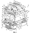
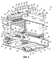
- Figs. 2-5 illustrate the cutting station 10 used to cut and separate a continuous chain of sealed product filled packages into individual contour cut packages by means of a singular cutting motion.
- the cutting station 10 includes a cutting head 12 having a planar top plate 14 connected, such as by fasteners 15, to depending side members 16, 17.
- a blade holder 18 carrying a plurality of dependent cutting blades 20 ( Figs. 3 and 4 ) is mounted on rods 21 for selective vertical movement beneath the top plate 14.
- the blade holder 18 is normally held upwardly against the bottom of the top plate 14 by a series of springs 22 passing through the top plate 14 and operatively connected to the blade holder 18.
- a number of other spring biased devices 24 ( Figs. 4 and 11 ) are positioned between the top plate 14 and the blade holder 18.
- An upper clamping plate 26 is suspended on rods 21 from the blade holder 18, and is configured to receive the blades 20 in a cutting operation to be described below in detail.
- An air valve 28 and a series of pneumatic cylinders 30 are provided on the top plate 14 for purposes to be further understood hereafter.
- the side members 16, 17 of the cutting head 12 are stationarily supported and fixed to a four post lifting arrangement including a pair of upper support bars 32, 34.
- the upper support bars 32, 34 are fixed to upper ends of a pair of front upright posts 36, 38 and a pair of rear upright posts 40, 42.
- Lower ends of the posts 36, 38 are connected to front support blocks 44, 46 positioned on front bearing blocks 48, 50 fixed to front ends of lower support bars 52, 54 which are anchored inside the frame of the packaging machine.
- lower ends of the rear posts 40, 42 are connected to rear support blocks 56, 58 mouhted on rear bearing blocks 60, 62 fixed to rear ends of the support bars 52, 54.
- a front shaft 64 has opposite ends mounted for rotation in the front bearing blocks 48, 50.
- a rear shaft 66 has opposite ends mounted for rotation in the rear bearing blocks 60, 62.
- a transverse support member 68 extends between mid-portions of the lower support bars 52, 54.
- a mounting plate arrangement 70 is provided across the rear ends of the lower support bars 52, 54.
- a servo motor 72 is positioned on the mounting plate arrangement 70, and is configured to selectively drive a pulley 74.
- a drive gear 76 is mounted on the rear shaft 66, and is connected in driving relationship with the pulley 74 by a belt 78 such that operation of the servo motor 72 will rotate the rear shaft 66 back and forth.
- a rear drive lever 80 is keyed to the rear shaft 66 inboard of drive gear 76, and a rear drive lever 82 is keyed to the rear shaft 66 opposite the drive lever 80.
- the rear drive lever 80 has a cam follower 84 which rides between upper and lower rails of a rear track 86.
- the rear drive lever 82 has a cam follower 88 which rides between upper and lower rails of a rear track 90.
- An upper end of rear drive lever 82 is connected to a rear end of a turnbuckle shaft 92 extending forwardly to a front follower lever 94 which is keyed to the front shaft 64.
- the front follower lever 94 has a cam follower 96 which rides between upper and lower rails of a front track 98.
- a rear follower lever 100 is also keyed to the front shaft 64, and provided with a cam follower 102 which rides between upper and lower rails of a front track 104.
- Each of the rear tracks 86, 90 and the front tracks 98, 104 is secured to lower rear and front portions of a pair of vertically moveable, longitudinally extending lifting bars 106, 108.
- a rear lower crossbar 110 connects rear ends of the lifting bars 106, 108.
- a rear upper cross bar 112 is joined to the rear lower crossbar 110, and has opposite ends connected to rear wear pieces 114, 116 which are configured to travel along rear posts 40, 42.
- a front lower cross bar 118 connects front ends of the lifting bars 106, 108.
- a front upper crossbar 120 is mounted on the front lower crossbar 118, and has opposite ends attached to front wear pieces 122, 124 which are designed to move along front posts 36, 38.
- a transverse support member 126 is provided between mid-portions of the lifting bars 106, 108.
- a lower clamping plate 128 is joined to a pair of depending sidewalls 130, 132 which are interconnected at lower ends by a bed 134.
- Connecting rails 136, 138 are provided on the bottom of the bed 134, and are joined to inside surfaces of the lifting bars 106, 108 between the rear crossbars 110, 112 and the front crossbars 118, 120.
- the lower clamping plate 128 is movable towards and away from the upper clamping plate 26. More specifically, the lower clamping plate 128 is movable between a closed position and an open position into and out of clamping engagement with a continuous chain of sealed product filled packages 137 conveyed between the upper clamping plate 26 and the lower clamping plate 128 in the direction of arrow A ( Fig. 5 ) after which a cutting operation occurs to provide separate individual packages 139.
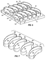
- a key feature of the present disclosure resides in the provision of a nested and contiguous arrangement of the cutting blades 20 mounted on the blade holder 18.
- the blades 20 are maintained in a desired alignment by means of guide blocks 140 which are engaged against rear walls 20f of the blades 20.
- the blades 20 are also held in aligned position by rods 142 which are passed through a series of recesses 144 formed in the blades 20.
- rods 142 which are passed through a series of recesses 144 formed in the blades 20.
- nuts are provided on the ends of the rods 142.
- Each blade 20 is formed with a serrated cutting edge 146 completely around its periphery.
- the blades 20 are formed as particularly bent kidney-shaped guillotine blades which are arranged in a two-by-five die pattern matrix or array to provide ten individual packages with peripheral contours shaped similar to the blades 20 in a single cutting motion upon indexing and clamping the continuous chain of sealed packages between the upper and lower clamping plates 26, 128.
- each longitudinally extending row of nested and contiguous blades 20 in the example shown include open crescent-shaped blades 20a, 20b, 20c, 20d, and a closed kidney-shaped blade 20e.
- Rear walls 20f of the blades 20b, 20c, 20d are nested and project into mouths 20g of adjacent blades 20a, 20b, 20c.
- the rear wall 20f of closed blade 20e is nested and projects into the mouth 20g of blade 20d.
- similarly shaped receiving structure for the particularly shaped blades 20 is formed in the upper clamping plate 26 and the lower clamping plate 128 to enable the desired separation of the contour cut packages.
- the upper clamping plate 26 is formed with two large contoured recesses 148, 150 suitably configured to matingly receive the nested arrangement of blades 20 which depend from the blade holder 18.
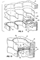
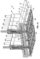
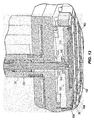
- a kidney-shaped internal clamping plate 152 is designed to be matingly received within the inner surface of each blade 20, and is connected to lower rod casing 154 ( Figs. 12 and 13 ) on each pneumatic cylinder 30.
- the bottom of each internal clamping plate 152 is formed with an annular groove 156 for receiving and retaining a gasket 158 ( Figs. 9-13 ).
- An extractor plate 160 is normally held within a recess 162 formed in the bottom surface of each internal clamping plate 152.
- the extractor plate 160 is connected to a rod 164 of each pneumatic cylinder 30, and passes through an opening 166 ( Figs. 9 and 10 ) formed in the internal clamping plate 152.
- the lower clamping plate 128 is constructed with a plurality of kidney-shaped recesses 168 which are designed to be continuously aligned beneath the internal clamping plates 152, and the extractor plates 160 mounted in the upper clamping plates 26. As best seen in Figs. 9, 10 and 14 , the lower clamping plate 128 is provided with blade receiving grooves 170 for receiving the cutting edges 146 of the blades 20 during a cutting and separating operation on the sealed packages formed on the packaging machine. Upper edges 172 of the lower clamping plate 128 located inwardly of the grooves 170 define clamping surfaces which are aligned with the gaskets 158 positioned in the upper clamping plate 26. Upper planar surface 174 ( Fig. 14 ) of the lower clamping plate 128 forms a further clamping surface which is aligned with a lower planar surface 176 on the upper clamping plate 26.
- the air valve 28 is mounted on the top plate 14, and provides, by means of a conduit 178, a source of pressurized air to a bladder 180 located between the bottom of the top plate 14 and the top of the blade holder 18. Adding pressurized air to the bladder 180 inflates and expands the bladder 180.
- the outer surfaces of the bladder 180 push the blade holder 18 away from the top plate 14 which simultaneously compresses the springs 22 and the spring biased devices 24, and forces the blades 20 downwardly into the grooves 170 in the lower clamping plate 128.
- Evacuating pressurized air from the bladder 180 deflates and contracts the bladder 180 such that the blades 20 are retracted from the grooves 170 and the blade holder 18 is returned towards the top plate 14 aided by the return force of the springs 22 and the devices 24.
- the packaging machine indexes and temporarily fixes in position the continuous chain of side-by-side closed and connected packages 137 in the two-by-five array as formed and sealed at the forming and closing stations 4, 8, respectively, upstream of the packaging machine 2 between the upper clamping plate 26 and the lower clamping plate 128 in its open position as depicted in Fig. 5 .
- each of the packaged products is aligned with a blade 20, an internal clamping plate 152, and an extractor plate 160 in the upper clamping plate 26, and a recess 168 in the lower clamping plate 128.
- Servo motor 72 is then operated as described above to move the lower clamping plate 128 upwardly so that the continuous chain of sealed packages is clamped between the upper clamping plate 26 and the lower clamping plate 128 in the closed position.
- the upper web of the sealed packages is tightly clamped by the lower planar surface 176 of the upper clamping plate 26 as well as by the gaskets 158.
- the lower web of the sealed packages is tightly clamped against the inside edges 172 and the upper planar surface 174 of the lower clamping plate 128.
- the pneumatic cylinders 30 are actuated to move the rod 164 and the connected extractor plates 160 downwardly so that the severed individual contoured cut packages 139 will drop by gravity through the recesses 168 of the lower clamping plate 128.
- the individual contoured cut packages 139 are designed to fall upon a discharge conveyor (not shown) which runs longitudinally along the top of bed 134.
- the inventors have found that greater efficiency and economy is achieved in providing the individual contoured cut packages as a direct result of the nested die pattern of blades 20 which requires less film or web material, and results in a substantial reduction in trim scrap waste and operating cost.
- the magnitude of the yearly savings in using the apparatus and method of the present disclosure can be understood by a typical example in which an existing die pattern comprised of similar kidney-shaped blades arranged in a two by five spaced apart matrix is compared with the two by five nested blade arrangement as disclosed above. With the existing die pattern of spaced a part blades, a total of 1,187.29 square inches of web material per index is required versus a total of 1,047.34 square inches of web material per index of the nested die pattern formed by the blades 20.
- the cutting station 10 is configured for ease of maintenance when, for example, it is desired to inspect or replace the blades 20 or other operating elements in the cutting head 12.
- the top plate 14 is pivotally mounted at a front edge relative to the side members 16, 17 by means of hinges 182 and hinge pins 184. Laterally extending handles 186 and U-shaped handles 188 are provided at a rear end of the top plate 14.
- a pair of gas ballasted cylinder assemblies 190, 192 is mounted between inner surfaces of the side members 16, 17 and the bottom of the top plate 14.
- top plate 14 Once fasteners 15 are removed from the top plate 14, a service operator can grasp the handles 186, 188 and pivot the top plate 14 with the blade holder 18 and the upper clamping plate 26 upwardly about the axes of the hinge pins 184. Beveled edges 194 ( Figure 11 ) are formed on the front ends of the side members 16, 17 to facilitate the pivoting motion.
- the top plate 14 is provided with eye bolts 196 which can be connected to a lifting device when it is desired to remove the entire cutting head 12 from the cutting station 10.
- the nested blade arrangement of the present disclosure has been found to be particularly useful in certain food and medical product packaging.
- the present disclosure illustrates the nested arrangement of the blades 20 oriented such that web travel occurs in a direction oriented along lengths of the blades 20.
- the present disclosure contemplates a similar nested arrangement of the blades 20 wherein web travel flows in a direction transverse to the lengths of the blades 20 as depicted in Figure 15 .
- the present disclosure further contemplates other nested arrangements of blades having other contours than described and illustrated herein which correspond to the desired contours of packages formed and sealed on the packaging machine.
Landscapes
- Engineering & Computer Science (AREA)
- Mechanical Engineering (AREA)
- Life Sciences & Earth Sciences (AREA)
- Forests & Forestry (AREA)
- Auxiliary Devices For And Details Of Packaging Control (AREA)
Applications Claiming Priority (2)
| Application Number | Priority Date | Filing Date | Title |
|---|---|---|---|
| US201562158739P | 2015-05-08 | 2015-05-08 | |
| US15/070,596 US20160325868A1 (en) | 2015-05-08 | 2016-03-15 | Contour cutting station for web packaging machine |
Publications (2)
| Publication Number | Publication Date |
|---|---|
| EP3090953A1 true EP3090953A1 (fr) | 2016-11-09 |
| EP3090953B1 EP3090953B1 (fr) | 2018-01-31 |
Family
ID=55854545
Family Applications (1)
| Application Number | Title | Priority Date | Filing Date |
|---|---|---|---|
| EP16000932.0A Not-in-force EP3090953B1 (fr) | 2015-05-08 | 2016-04-26 | Station de coupe pour une machine d'emballage en bande |
Country Status (2)
| Country | Link |
|---|---|
| US (1) | US20160325868A1 (fr) |
| EP (1) | EP3090953B1 (fr) |
Cited By (1)
| Publication number | Priority date | Publication date | Assignee | Title |
|---|---|---|---|---|
| CN108163293A (zh) * | 2018-01-11 | 2018-06-15 | 浙江佑天元包装机械制造有限公司 | 一种气调包装机封切机构 |
Families Citing this family (14)
| Publication number | Priority date | Publication date | Assignee | Title |
|---|---|---|---|---|
| USD810163S1 (en) * | 2015-06-01 | 2018-02-13 | Bobst Mex Sa | Packaging machine |
| USD837850S1 (en) * | 2016-05-18 | 2019-01-08 | Bobst Mex Sa | Packaging machine |
| USD839938S1 (en) * | 2016-05-18 | 2019-02-05 | Bobst Mex Sa | Packaging machine |
| USD837849S1 (en) * | 2016-05-18 | 2019-01-08 | Bobst Mex Sa | Packaging machine |
| USD836689S1 (en) * | 2016-11-30 | 2018-12-25 | Bobst Bielefeld Gmbh | Packaging machines |
| USD938501S1 (en) * | 2019-01-11 | 2021-12-14 | Doosan Machine Tools Co., Ltd. | Machine center |
| USD932525S1 (en) * | 2019-01-11 | 2021-10-05 | Doosan Machine Tools Co., Ltd. | Machine center |
| USD932526S1 (en) * | 2019-01-11 | 2021-10-05 | Doosan Machine Tools Co., Ltd. | Machine center |
| USD918277S1 (en) * | 2019-06-07 | 2021-05-04 | Bühler AG | Die casting machine |
| EP3795473B1 (fr) | 2019-09-17 | 2022-09-14 | Bombardier Inc. | Aéronef avec un divan d'aéronef |
| CN111546550B (zh) * | 2020-05-14 | 2021-04-09 | 鹤山市吉新海绵有限公司 | 一种工业吸音海绵制备自动化加工系统及制备加工方法 |
| USD923670S1 (en) * | 2020-06-22 | 2021-06-29 | Doosan Machine Tools Co., Ltd. | Machine center |
| CN115535393B (zh) * | 2022-10-09 | 2025-11-04 | 合肥龙延智能科技股份有限公司 | 一种包装托具加工用冲裁机构 |
| USD1098226S1 (en) * | 2023-05-02 | 2025-10-14 | SOMIC Verpackungsmaschinen GmbH & Co. KG | Housing for packaging machines and parts thereof |
Citations (6)
| Publication number | Priority date | Publication date | Assignee | Title |
|---|---|---|---|---|
| JPS54140379U (fr) * | 1978-03-24 | 1979-09-29 | ||
| DE2853267A1 (de) * | 1978-12-09 | 1980-07-24 | Applic Plastique Mec Elec | Vorrichtung zum ausstanzen von behaeltern |
| US5170611A (en) | 1990-12-12 | 1992-12-15 | Rapidpak, Inc. | Web supply mechanism for an indexing motion packaging machine |
| US5205110A (en) | 1990-12-12 | 1993-04-27 | Buchko Raymond G | Servo motor operated indexing motion packaging machine and method |
| US20030014945A1 (en) * | 2001-07-19 | 2003-01-23 | Danby Hal C. | Apparatus, method and flexible bag for use in manufacturing |
| US20030221535A1 (en) * | 2002-04-01 | 2003-12-04 | Sargento Foods Inc. | Structure and method for cutting slabs of natural cheeses into shape (s) via cutting blades of a pattern such that the shape (s) are tessellated or nested |
Family Cites Families (31)
| Publication number | Priority date | Publication date | Assignee | Title |
|---|---|---|---|---|
| US2523178A (en) * | 1948-11-04 | 1950-09-19 | Jack M Zeprun | Baigle cutting machine |
| US3469541A (en) * | 1967-10-02 | 1969-09-30 | Nat Biscuit Co | Method for preparing cookies for packaging and freezing |
| US3759122A (en) * | 1972-05-22 | 1973-09-18 | Filper Corp | Package separator and corner cutting die for individual portions, and method |
| US3864829A (en) * | 1973-08-10 | 1975-02-11 | John Williams | Cutting tool |
| US4233801A (en) * | 1978-07-31 | 1980-11-18 | Ashley-Butler, Inc. | Apparatus and process for the manufacture of disposable thermometers |
| US4210041A (en) * | 1979-02-08 | 1980-07-01 | Enrique Mitman | Method for cutting a plurality of identical, irregular, non-polygonal pieces from material with minimum waste |
| US4694717A (en) * | 1985-08-05 | 1987-09-22 | A. Duda & Sons, Inc. | Single pass sod cutting machine for producing hexagonally shaped plugs |
| US4730761A (en) * | 1986-08-15 | 1988-03-15 | Personal Products Company | Cutting flexible formed products from foam retaining sheet |
| US4836070A (en) * | 1986-08-15 | 1989-06-06 | Personal Products Company | Method and apparatus for producing fibrous web pieces |
| US5676032A (en) * | 1995-10-20 | 1997-10-14 | Southwest Die Corporation | Steel rule die with closely nested cavities |
| US5911805A (en) * | 1996-05-31 | 1999-06-15 | Sterr; Ardina K. | Specialty die cut confetti and a method of manufacture |
| US5964134A (en) * | 1997-06-11 | 1999-10-12 | Arends; Albert W. | Trim apparatus and method for trimming an article from a thermoplastic sheet |
| US6192778B1 (en) * | 1999-02-02 | 2001-02-27 | Thies Eggers | Cutting apparatus for separating packages from a line |
| EA200200139A1 (ru) * | 1999-07-27 | 2002-08-29 | Санфорд Редмонд Инк. | Компактная машина для формования, заполнения и герметичного закрытия упаковок |
| US6435067B1 (en) * | 2000-05-22 | 2002-08-20 | Jere F. Irwin | Apparatus and method for registering articles during a web processing operation |
| DE10230365B8 (de) * | 2002-07-05 | 2008-09-25 | Mühlbauer Ag | Vorrichtung und Verfahren zum Heraustrennen von Kunststoffkarten |
| US6843043B2 (en) * | 2002-09-13 | 2005-01-18 | Alkar Rapidpak, Inc. | Web packaging pasteurization system |
| US6953596B2 (en) * | 2002-09-18 | 2005-10-11 | General Mills, Inc. | Method and apparatus for cutting dough with nested pattern cutters |
| AU2003283105A1 (en) * | 2002-11-07 | 2004-06-07 | Ontario Die International Inc | Method and device for mounting a steel rule cutting die with improved scrap material removal |
| US20070186740A1 (en) * | 2006-01-20 | 2007-08-16 | Steven Dreyer | Method and apparatus for forming and cutting vinyl tiles with rolled edges |
| US7490448B1 (en) * | 2007-03-09 | 2009-02-17 | Alkar-Rapidpak, Inc. | Form-fill-seal web packaging system with sealing station |
| US8048465B2 (en) * | 2009-02-03 | 2011-11-01 | Kraft Foods Global Brands Llc | Methods for producing elbow-shaped crackers |
| US8499536B2 (en) * | 2009-05-18 | 2013-08-06 | Alkar-Rapidpak-Mp Equipment, Inc. | Apparatuses and methods for assisted tooling extraction |
| US20120207899A1 (en) * | 2011-02-15 | 2012-08-16 | Boris Serebryany | Method and apparatus for cutting dough products having holes from a dough sheet |
| DE102011115142B4 (de) * | 2011-09-27 | 2017-09-21 | Multivac Sepp Haggenmüller Se & Co. Kg | Verfahren zum Vereinzeln von Verpackungen |
| EP2594496B1 (fr) * | 2011-11-17 | 2015-04-08 | Cryovac, Inc. | Appareil de conditionnement comportant un découpeur pour découper un film |
| DE102012000127A1 (de) * | 2012-01-06 | 2013-07-11 | Gea Cfs Germany Gmbh | Verpackungsmaschine mit einer Schneidstation |
| GB2515636B (en) * | 2012-03-16 | 2016-08-31 | Tap Biosystems (Phc) Ltd | Method and apparatus for selectively lifiting individual tubes from an array of tubes within in a storage area |
| EP2994393B1 (fr) * | 2013-05-07 | 2017-03-08 | Cryovac, Inc. | Appareil et procédé d'emballage d'un produit |
| WO2015004085A1 (fr) * | 2013-07-09 | 2015-01-15 | Brita Gmbh | Procédé et appareil de fabrication d'un élément de traitement de fluide |
| DE102014000133B4 (de) * | 2014-01-13 | 2015-10-15 | Melzer Maschinenbau Gmbh | Verfahren und Einrichtung zur Bearbeitung eines Substrats |
-
2016
- 2016-03-15 US US15/070,596 patent/US20160325868A1/en not_active Abandoned
- 2016-04-26 EP EP16000932.0A patent/EP3090953B1/fr not_active Not-in-force
Patent Citations (7)
| Publication number | Priority date | Publication date | Assignee | Title |
|---|---|---|---|---|
| JPS54140379U (fr) * | 1978-03-24 | 1979-09-29 | ||
| DE2853267A1 (de) * | 1978-12-09 | 1980-07-24 | Applic Plastique Mec Elec | Vorrichtung zum ausstanzen von behaeltern |
| US5170611A (en) | 1990-12-12 | 1992-12-15 | Rapidpak, Inc. | Web supply mechanism for an indexing motion packaging machine |
| US5205110A (en) | 1990-12-12 | 1993-04-27 | Buchko Raymond G | Servo motor operated indexing motion packaging machine and method |
| US5205110C1 (en) | 1990-12-12 | 2001-05-15 | Dec Int | Servo motor operated indexing motion packaging machine and method |
| US20030014945A1 (en) * | 2001-07-19 | 2003-01-23 | Danby Hal C. | Apparatus, method and flexible bag for use in manufacturing |
| US20030221535A1 (en) * | 2002-04-01 | 2003-12-04 | Sargento Foods Inc. | Structure and method for cutting slabs of natural cheeses into shape (s) via cutting blades of a pattern such that the shape (s) are tessellated or nested |
Cited By (2)
| Publication number | Priority date | Publication date | Assignee | Title |
|---|---|---|---|---|
| CN108163293A (zh) * | 2018-01-11 | 2018-06-15 | 浙江佑天元包装机械制造有限公司 | 一种气调包装机封切机构 |
| CN108163293B (zh) * | 2018-01-11 | 2024-05-07 | 浙江佑天元包装机械制造有限公司 | 一种气调包装机封切机构 |
Also Published As
| Publication number | Publication date |
|---|---|
| EP3090953B1 (fr) | 2018-01-31 |
| US20160325868A1 (en) | 2016-11-10 |
Similar Documents
| Publication | Publication Date | Title |
|---|---|---|
| EP3090953B1 (fr) | Station de coupe pour une machine d'emballage en bande | |
| US7886645B2 (en) | Exact weight cutting and destacking system for food products | |
| WO2015194983A1 (fr) | Machine comportant un couteau à ruban sans fin de coupe de panneaux éponge en morceaux | |
| EP2253544A2 (fr) | Appareil de conditionnement par indexation de mouvement et machine | |
| EP0000821B1 (fr) | Procédé et appareil pour rétrécir des boyaux remplis | |
| JP5462181B2 (ja) | プラスチック容器を使用のために調整する装置 | |
| US20100212465A1 (en) | Cutting Machine for the Cutting of Blocks of Material | |
| DE10204296A1 (de) | Vorrichtung zum dreiseitigen Beschneiden von Druckprodukten | |
| CN113056423B (zh) | 用于准备由塑料制成的容器以便容器使用的设备 | |
| US20030221535A1 (en) | Structure and method for cutting slabs of natural cheeses into shape (s) via cutting blades of a pattern such that the shape (s) are tessellated or nested | |
| US4553418A (en) | Apparatus for producing elongated workpieces of predetermined transverse profile | |
| US5964134A (en) | Trim apparatus and method for trimming an article from a thermoplastic sheet | |
| US3502127A (en) | Meat cutting machine | |
| JP6407667B2 (ja) | 食品生地片の切断移送装置および方法 | |
| US4036123A (en) | Machine of cutting cores of vegetables | |
| CA2440525C (fr) | Structure et methode de coupe de plaques de fromages naturels en forme(s) au moyen de lames de coupe dont le gabarit permet d'obtenir des formes carrelees ou imbriquees | |
| CN109436476B (zh) | 一种食品快速剪切加工装袋装置 | |
| IT202100016646A1 (it) | Procedimento di taglio e denocciolatura di pesche e relativa macchina a più linee | |
| US20250169529A1 (en) | A food processing machine and methods of operation thereof | |
| US2822004A (en) | Machine for cutting non-rigid material into blocks | |
| CN208699239U (zh) | 一种方块红糖枕式包装机的修边装置 | |
| US7530303B2 (en) | Cheese wheel cutter | |
| CN113277165A (zh) | 流水线型全自动保鲜膜包装机 | |
| CN205240002U (zh) | 蛋酥输送分选装置 | |
| US20240253258A1 (en) | Variable length gripper assembly for a food slicing machine and method of operating same |
Legal Events
| Date | Code | Title | Description |
|---|---|---|---|
| PUAI | Public reference made under article 153(3) epc to a published international application that has entered the european phase |
Free format text: ORIGINAL CODE: 0009012 |
|
| AK | Designated contracting states |
Kind code of ref document: A1 Designated state(s): AL AT BE BG CH CY CZ DE DK EE ES FI FR GB GR HR HU IE IS IT LI LT LU LV MC MK MT NL NO PL PT RO RS SE SI SK SM TR |
|
| AX | Request for extension of the european patent |
Extension state: BA ME |
|
| 17P | Request for examination filed |
Effective date: 20170424 |
|
| RBV | Designated contracting states (corrected) |
Designated state(s): AL AT BE BG CH CY CZ DE DK EE ES FI FR GB GR HR HU IE IS IT LI LT LU LV MC MK MT NL NO PL PT RO RS SE SI SK SM TR |
|
| GRAP | Despatch of communication of intention to grant a patent |
Free format text: ORIGINAL CODE: EPIDOSNIGR1 |
|
| INTG | Intention to grant announced |
Effective date: 20170831 |
|
| GRAS | Grant fee paid |
Free format text: ORIGINAL CODE: EPIDOSNIGR3 |
|
| GRAA | (expected) grant |
Free format text: ORIGINAL CODE: 0009210 |
|
| AK | Designated contracting states |
Kind code of ref document: B1 Designated state(s): AL AT BE BG CH CY CZ DE DK EE ES FI FR GB GR HR HU IE IS IT LI LT LU LV MC MK MT NL NO PL PT RO RS SE SI SK SM TR |
|
| REG | Reference to a national code |
Ref country code: GB Ref legal event code: FG4D Ref country code: CH Ref legal event code: EP |
|
| REG | Reference to a national code |
Ref country code: AT Ref legal event code: REF Ref document number: 967117 Country of ref document: AT Kind code of ref document: T Effective date: 20180215 |
|
| REG | Reference to a national code |
Ref country code: IE Ref legal event code: FG4D |
|
| REG | Reference to a national code |
Ref country code: DE Ref legal event code: R096 Ref document number: 602016001460 Country of ref document: DE |
|
| REG | Reference to a national code |
Ref country code: NL Ref legal event code: MP Effective date: 20180131 |
|
| REG | Reference to a national code |
Ref country code: LT Ref legal event code: MG4D |
|
| REG | Reference to a national code |
Ref country code: AT Ref legal event code: MK05 Ref document number: 967117 Country of ref document: AT Kind code of ref document: T Effective date: 20180131 |
|
| PG25 | Lapsed in a contracting state [announced via postgrant information from national office to epo] |
Ref country code: NO Free format text: LAPSE BECAUSE OF FAILURE TO SUBMIT A TRANSLATION OF THE DESCRIPTION OR TO PAY THE FEE WITHIN THE PRESCRIBED TIME-LIMIT Effective date: 20180430 Ref country code: ES Free format text: LAPSE BECAUSE OF FAILURE TO SUBMIT A TRANSLATION OF THE DESCRIPTION OR TO PAY THE FEE WITHIN THE PRESCRIBED TIME-LIMIT Effective date: 20180131 Ref country code: LT Free format text: LAPSE BECAUSE OF FAILURE TO SUBMIT A TRANSLATION OF THE DESCRIPTION OR TO PAY THE FEE WITHIN THE PRESCRIBED TIME-LIMIT Effective date: 20180131 Ref country code: NL Free format text: LAPSE BECAUSE OF FAILURE TO SUBMIT A TRANSLATION OF THE DESCRIPTION OR TO PAY THE FEE WITHIN THE PRESCRIBED TIME-LIMIT Effective date: 20180131 Ref country code: HR Free format text: LAPSE BECAUSE OF FAILURE TO SUBMIT A TRANSLATION OF THE DESCRIPTION OR TO PAY THE FEE WITHIN THE PRESCRIBED TIME-LIMIT Effective date: 20180131 Ref country code: FI Free format text: LAPSE BECAUSE OF FAILURE TO SUBMIT A TRANSLATION OF THE DESCRIPTION OR TO PAY THE FEE WITHIN THE PRESCRIBED TIME-LIMIT Effective date: 20180131 |
|
| PG25 | Lapsed in a contracting state [announced via postgrant information from national office to epo] |
Ref country code: PL Free format text: LAPSE BECAUSE OF FAILURE TO SUBMIT A TRANSLATION OF THE DESCRIPTION OR TO PAY THE FEE WITHIN THE PRESCRIBED TIME-LIMIT Effective date: 20180131 Ref country code: GR Free format text: LAPSE BECAUSE OF FAILURE TO SUBMIT A TRANSLATION OF THE DESCRIPTION OR TO PAY THE FEE WITHIN THE PRESCRIBED TIME-LIMIT Effective date: 20180501 Ref country code: LV Free format text: LAPSE BECAUSE OF FAILURE TO SUBMIT A TRANSLATION OF THE DESCRIPTION OR TO PAY THE FEE WITHIN THE PRESCRIBED TIME-LIMIT Effective date: 20180131 Ref country code: AT Free format text: LAPSE BECAUSE OF FAILURE TO SUBMIT A TRANSLATION OF THE DESCRIPTION OR TO PAY THE FEE WITHIN THE PRESCRIBED TIME-LIMIT Effective date: 20180131 Ref country code: BG Free format text: LAPSE BECAUSE OF FAILURE TO SUBMIT A TRANSLATION OF THE DESCRIPTION OR TO PAY THE FEE WITHIN THE PRESCRIBED TIME-LIMIT Effective date: 20180430 Ref country code: RS Free format text: LAPSE BECAUSE OF FAILURE TO SUBMIT A TRANSLATION OF THE DESCRIPTION OR TO PAY THE FEE WITHIN THE PRESCRIBED TIME-LIMIT Effective date: 20180131 Ref country code: IS Free format text: LAPSE BECAUSE OF FAILURE TO SUBMIT A TRANSLATION OF THE DESCRIPTION OR TO PAY THE FEE WITHIN THE PRESCRIBED TIME-LIMIT Effective date: 20180531 Ref country code: SE Free format text: LAPSE BECAUSE OF FAILURE TO SUBMIT A TRANSLATION OF THE DESCRIPTION OR TO PAY THE FEE WITHIN THE PRESCRIBED TIME-LIMIT Effective date: 20180131 |
|
| PG25 | Lapsed in a contracting state [announced via postgrant information from national office to epo] |
Ref country code: EE Free format text: LAPSE BECAUSE OF FAILURE TO SUBMIT A TRANSLATION OF THE DESCRIPTION OR TO PAY THE FEE WITHIN THE PRESCRIBED TIME-LIMIT Effective date: 20180131 Ref country code: AL Free format text: LAPSE BECAUSE OF FAILURE TO SUBMIT A TRANSLATION OF THE DESCRIPTION OR TO PAY THE FEE WITHIN THE PRESCRIBED TIME-LIMIT Effective date: 20180131 Ref country code: RO Free format text: LAPSE BECAUSE OF FAILURE TO SUBMIT A TRANSLATION OF THE DESCRIPTION OR TO PAY THE FEE WITHIN THE PRESCRIBED TIME-LIMIT Effective date: 20180131 Ref country code: IT Free format text: LAPSE BECAUSE OF FAILURE TO SUBMIT A TRANSLATION OF THE DESCRIPTION OR TO PAY THE FEE WITHIN THE PRESCRIBED TIME-LIMIT Effective date: 20180131 |
|
| REG | Reference to a national code |
Ref country code: DE Ref legal event code: R097 Ref document number: 602016001460 Country of ref document: DE |
|
| PG25 | Lapsed in a contracting state [announced via postgrant information from national office to epo] |
Ref country code: MC Free format text: LAPSE BECAUSE OF FAILURE TO SUBMIT A TRANSLATION OF THE DESCRIPTION OR TO PAY THE FEE WITHIN THE PRESCRIBED TIME-LIMIT Effective date: 20180131 Ref country code: CZ Free format text: LAPSE BECAUSE OF FAILURE TO SUBMIT A TRANSLATION OF THE DESCRIPTION OR TO PAY THE FEE WITHIN THE PRESCRIBED TIME-LIMIT Effective date: 20180131 Ref country code: DK Free format text: LAPSE BECAUSE OF FAILURE TO SUBMIT A TRANSLATION OF THE DESCRIPTION OR TO PAY THE FEE WITHIN THE PRESCRIBED TIME-LIMIT Effective date: 20180131 Ref country code: SM Free format text: LAPSE BECAUSE OF FAILURE TO SUBMIT A TRANSLATION OF THE DESCRIPTION OR TO PAY THE FEE WITHIN THE PRESCRIBED TIME-LIMIT Effective date: 20180131 Ref country code: SK Free format text: LAPSE BECAUSE OF FAILURE TO SUBMIT A TRANSLATION OF THE DESCRIPTION OR TO PAY THE FEE WITHIN THE PRESCRIBED TIME-LIMIT Effective date: 20180131 |
|
| PLBE | No opposition filed within time limit |
Free format text: ORIGINAL CODE: 0009261 |
|
| STAA | Information on the status of an ep patent application or granted ep patent |
Free format text: STATUS: NO OPPOSITION FILED WITHIN TIME LIMIT |
|
| REG | Reference to a national code |
Ref country code: BE Ref legal event code: MM Effective date: 20180430 |
|
| 26N | No opposition filed |
Effective date: 20181102 |
|
| REG | Reference to a national code |
Ref country code: IE Ref legal event code: MM4A |
|
| PG25 | Lapsed in a contracting state [announced via postgrant information from national office to epo] |
Ref country code: LU Free format text: LAPSE BECAUSE OF NON-PAYMENT OF DUE FEES Effective date: 20180426 |
|
| PG25 | Lapsed in a contracting state [announced via postgrant information from national office to epo] |
Ref country code: BE Free format text: LAPSE BECAUSE OF NON-PAYMENT OF DUE FEES Effective date: 20180430 Ref country code: SI Free format text: LAPSE BECAUSE OF FAILURE TO SUBMIT A TRANSLATION OF THE DESCRIPTION OR TO PAY THE FEE WITHIN THE PRESCRIBED TIME-LIMIT Effective date: 20180131 |
|
| PG25 | Lapsed in a contracting state [announced via postgrant information from national office to epo] |
Ref country code: FR Free format text: LAPSE BECAUSE OF NON-PAYMENT OF DUE FEES Effective date: 20180430 Ref country code: IE Free format text: LAPSE BECAUSE OF NON-PAYMENT OF DUE FEES Effective date: 20180426 |
|
| REG | Reference to a national code |
Ref country code: CH Ref legal event code: PL |
|
| PG25 | Lapsed in a contracting state [announced via postgrant information from national office to epo] |
Ref country code: CH Free format text: LAPSE BECAUSE OF NON-PAYMENT OF DUE FEES Effective date: 20190430 Ref country code: LI Free format text: LAPSE BECAUSE OF NON-PAYMENT OF DUE FEES Effective date: 20190430 Ref country code: MT Free format text: LAPSE BECAUSE OF NON-PAYMENT OF DUE FEES Effective date: 20180426 |
|
| PG25 | Lapsed in a contracting state [announced via postgrant information from national office to epo] |
Ref country code: TR Free format text: LAPSE BECAUSE OF FAILURE TO SUBMIT A TRANSLATION OF THE DESCRIPTION OR TO PAY THE FEE WITHIN THE PRESCRIBED TIME-LIMIT Effective date: 20180131 |
|
| PG25 | Lapsed in a contracting state [announced via postgrant information from national office to epo] |
Ref country code: PT Free format text: LAPSE BECAUSE OF FAILURE TO SUBMIT A TRANSLATION OF THE DESCRIPTION OR TO PAY THE FEE WITHIN THE PRESCRIBED TIME-LIMIT Effective date: 20180131 |
|
| PG25 | Lapsed in a contracting state [announced via postgrant information from national office to epo] |
Ref country code: CY Free format text: LAPSE BECAUSE OF FAILURE TO SUBMIT A TRANSLATION OF THE DESCRIPTION OR TO PAY THE FEE WITHIN THE PRESCRIBED TIME-LIMIT Effective date: 20180131 Ref country code: HU Free format text: LAPSE BECAUSE OF FAILURE TO SUBMIT A TRANSLATION OF THE DESCRIPTION OR TO PAY THE FEE WITHIN THE PRESCRIBED TIME-LIMIT; INVALID AB INITIO Effective date: 20160426 Ref country code: MK Free format text: LAPSE BECAUSE OF NON-PAYMENT OF DUE FEES Effective date: 20180131 |
|
| GBPC | Gb: european patent ceased through non-payment of renewal fee |
Effective date: 20200426 |
|
| PG25 | Lapsed in a contracting state [announced via postgrant information from national office to epo] |
Ref country code: GB Free format text: LAPSE BECAUSE OF NON-PAYMENT OF DUE FEES Effective date: 20200426 |
|
| PGFP | Annual fee paid to national office [announced via postgrant information from national office to epo] |
Ref country code: DE Payment date: 20210318 Year of fee payment: 6 |
|
| REG | Reference to a national code |
Ref country code: DE Ref legal event code: R081 Ref document number: 602016001460 Country of ref document: DE Owner name: MIDDLEBY PACKAGING SOLUTIONS, LLC, ELGIN, US Free format text: FORMER OWNER: ALKAR-RAPIDPAK, INC., LODI, WIS., US |
|
| REG | Reference to a national code |
Ref country code: DE Ref legal event code: R119 Ref document number: 602016001460 Country of ref document: DE |
|
| PG25 | Lapsed in a contracting state [announced via postgrant information from national office to epo] |
Ref country code: DE Free format text: LAPSE BECAUSE OF NON-PAYMENT OF DUE FEES Effective date: 20221103 |