EP3091173A1 - Installation de forage destinee a produire ou a elargir un forage terrestre dans la terre et procede de commande d'un dispositif d'avance d'une telle installation de forage - Google Patents
Installation de forage destinee a produire ou a elargir un forage terrestre dans la terre et procede de commande d'un dispositif d'avance d'une telle installation de forage Download PDFInfo
- Publication number
- EP3091173A1 EP3091173A1 EP16168005.3A EP16168005A EP3091173A1 EP 3091173 A1 EP3091173 A1 EP 3091173A1 EP 16168005 A EP16168005 A EP 16168005A EP 3091173 A1 EP3091173 A1 EP 3091173A1
- Authority
- EP
- European Patent Office
- Prior art keywords
- feed
- force
- drive
- value
- feed force
- Prior art date
- Legal status (The legal status is an assumption and is not a legal conclusion. Google has not performed a legal analysis and makes no representation as to the accuracy of the status listed.)
- Granted
Links
Images

Classifications
-
- E—FIXED CONSTRUCTIONS
- E21—EARTH OR ROCK DRILLING; MINING
- E21B—EARTH OR ROCK DRILLING; OBTAINING OIL, GAS, WATER, SOLUBLE OR MELTABLE MATERIALS OR A SLURRY OF MINERALS FROM WELLS
- E21B44/00—Automatic control systems specially adapted for drilling operations, i.e. self-operating systems which function to carry out or modify a drilling operation without intervention of a human operator, e.g. computer-controlled drilling systems; Systems specially adapted for monitoring a plurality of drilling variables or conditions
- E21B44/02—Automatic control of the tool feed
- E21B44/04—Automatic control of the tool feed in response to the torque of the drive ; Measuring drilling torque
-
- E—FIXED CONSTRUCTIONS
- E21—EARTH OR ROCK DRILLING; MINING
- E21B—EARTH OR ROCK DRILLING; OBTAINING OIL, GAS, WATER, SOLUBLE OR MELTABLE MATERIALS OR A SLURRY OF MINERALS FROM WELLS
- E21B44/00—Automatic control systems specially adapted for drilling operations, i.e. self-operating systems which function to carry out or modify a drilling operation without intervention of a human operator, e.g. computer-controlled drilling systems; Systems specially adapted for monitoring a plurality of drilling variables or conditions
- E21B44/02—Automatic control of the tool feed
-
- E—FIXED CONSTRUCTIONS
- E21—EARTH OR ROCK DRILLING; MINING
- E21B—EARTH OR ROCK DRILLING; OBTAINING OIL, GAS, WATER, SOLUBLE OR MELTABLE MATERIALS OR A SLURRY OF MINERALS FROM WELLS
- E21B7/00—Special methods or apparatus for drilling
- E21B7/28—Enlarging drilled holes, e.g. by counterboring
Definitions
- the invention relates to a method for controlling a feed drive of a drilling rig for generating or expanding a ground hole in the ground, wherein a drill pipe connected to the drilling and / or expansion tool is rotated about its longitudinal axis by means of a rotary drive and with the aid of the feed drive in the direction of its longitudinal axis is moved through the soil.
- the force exerted by the feed drive on the drill string in the direction of its longitudinal axis feed force is limited to a preset value.
- the invention relates to a drilling rig for generating or expanding a hole in the ground.
- a method and a device for controlling the feed drive of a drilling rig intended for producing wells are known.
- the drilling rig has a drill string carrying drill string that is advanced with simultaneous rotation in the soil.
- the feed rate of the feed drive is controlled in dependence on the torque occurring at the drill string.
- Other horizontal drilling rigs with a feed drive for driving a boring rod carrying a drilling tool, which advanced with simultaneous rotation by means of a feed drive in the ground is, are from the documents DE 10 2010 004 287 A1 and US 6,189,628 B1 known.
- a target value for the torque acting on the drill pipe to the rotation torque M is set.
- a control unit controls the feed rate of a drilling tool to be moved through the soil or a flaring tool to be moved through the soil with a pipe to be pulled into the opening created by means of the flaring tool so that a detected actual torque Mist is equal to the preset target value M soll is.
- the feed speed v is increased until the actual torque Mist reaches the preset setpoint M soll . If the substrate is homogeneous, the expansion tool is then moved through the soil at a relatively constant pull-in speed. If the substrate becomes harder or hits the drilling and / or expansion tool on a rock or rock, the effective torque Mist is greater than the target value M soll . Then the feed is stopped until the drilling and / or expansion tool has rotated freely and the current torque acting M is again smaller than the set value M is intended. Subsequently, the feed rate is increased again until the current value of the torque M ist has reached the setpoint.
- both the drilling of a pilot hole by means of a drilling tool and the widening of the pilot hole or the widening of an opening already present in the ground in the prior art always takes place with the maximum retraction force. Depending on the substrate, this can lead to the carbide teeth of a drilling tool or a widening tool so pressed into the ground or in rock or pulled that they get caught in the soil or rock. As a result, the drilling tool or the expander head can not continue to turn and stops.
- a drill string connected to a drilling and / or expansion tool is rotated about its longitudinal axis by means of a rotary drive of the drilling rig and by means of the feed drive in the direction of its longitudinal axis through the Earth area moves. Furthermore, the feed force exerted by the feed drive on the drill string in the direction of its longitudinal axis is limited to a preset value.
- the feed drive is preferably a feed drive unit which generates a translatory drive movement of the drill string.
- the drilling and / or expansion tool is either pushed away from the feed drive into the soil or pulled towards the feed drive through the soil.
- the drilling and / or expansion tool is at least in a rotational direction at the remote from the feed drive end of the drill string rotatably connected thereto.
- Such a method for controlling the feed drive prevents the drilling tool or the expansion tool is pressed with a large force against the ground, in particular a blockage of the drilling tool is prevented due to excessive feed force.
- a suitable restriction of the feed force is ensured that an abrupt snagging of cutting elements of the drilling and / or Aufweitwerkmaschines is prevented with the soil, thereby causing such a blockage of the drilling and / or Aufweitwerkmaschines interruption of the drilling process and extreme loads on the drill string and the drilling tool can be avoided.
- the feed force is determined as the actual value and if the determined actual value is compared with a preset desired value. Upon reaching and / or exceeding the preset target value, the feed force exerted by the feed drive on the drill string is reduced. Preferably, the amount of the feed force is determined as the actual value and compared with the preset target value. As a result, a simple and safe monitoring and limiting the feed force is possible.
- the feed force is selectively exerted on the drill string in such a way that the drilling and / or expansion tool connected to the drill string is moved away from the feed drive or toward the feed drive by the feed force.
- the drilling rig can move the drilling and / or expansion tool both away from the feed drive and move towards the feed drive, so that in a simple manner a pilot hole can be made through the soil using a drilling tool and then the drilling tool at the end of the drill pipe of this is disconnected and the end of the drill string is connected to a Aufweitwerkmaschine, the Expansion tool then moved to the feed drive, that is pulled through the soil, is.
- the feed rate of the drill string and / or the feed force exerted on the drill string are set as a function of the torque exerted on the drill string for its rotation.
- the feed rate and / or the feed force can be used as a manipulated variable in a control loop for controlling the torque.
- the manipulated variables feed force and feed rate are adjusted together until one of the manipulated variables reaches a lower and / or upper preset limit value. Subsequently, only the other control variable is adjusted further.
- the torque exerted on the drill pipe for its rotation is determined as the actual value and compared with a preset desired value, and if a system deviation is determined from the difference between desired value and actual value.
- a positive control deviation the feed rate and / or the feed force are reduced and with a negative control deviation, the feed rate and the feed force are increased.
- the feed force is increased with a positive control deviation until it has reached the preset value.
- the feed force is not further increased, even with a positive control deviation.
- an operator can change the preset value, so that then, depending on the determined control deviation with a positive control deviation, the feed force can be further increased to the new preset limit.
- the feed force and the feed rate are simultaneously increased until the feed force has reached the pre-set value.
- the feed force and the feed rate are reduced simultaneously until no more control deviation or a positive control deviation is detected.
- the drive unit used is preferably a hydraulic unit, wherein the pressure generated by the hydraulic unit on the hydraulic unit can be adjusted independently of the quantity of hydraulic fluid delivered by the hydraulic unit.
- the pressure generated by the hydraulic unit is a measure of the feed force and the amount delivered by the hydraulic unit is a measure of the feed rate.
- the feed force and the feed rate can be predefined on the hydraulic unit in a simple manner.
- the specification of these values is carried out in particular by a Control unit of the drilling rig, which is connected via a suitable interface with the hydraulic power unit for the specification of nominal values for pressure and quantity.
- the control unit is preferably a programmable logic controller of the drilling rig.
- the preset value of the feed force and / or the preset value of the feed rate can be set via an operating unit and changed during operation of the drilling system by an operator or by specifying a further control unit or a control algorithm.
- the actual value of the torque is preferably determined on the basis of the rotary drive force acting on the drill pipe.
- the rotary drive force can be determined in a hydraulic drive of the drill string simply due to the pressure of the hydraulic fluid supplied to the hydraulic motor.
- both the rotary drive and the feed drive are hydraulic drives.
- the amount of the pressure medium supplied to the feed drive in particular the hydraulic fluid supplied to the feed drive, is changed.
- the feed force of the pressure of the feed drive supplied pressure medium in particular of the feed drive hydraulic fluid is changed.
- the preset value for limiting the feed force before the start of a wellbore is set, preferably to a value in the range between 20% and 40%.
- the desired value of the torque is preset to a value in the range of 70% to 90% of the torque generated by the rotary drive for rotating the drill string.
- a second aspect of the invention relates to a drilling rig for generating or expanding a ground hole in the ground, preferably according to the method with the features of claim 1 or a previously described development of this method.
- the drilling rig has a feed drive which applies a feed force to a drill string and moves a drilling and / or expansion tool connected to the drill string in the direction of the longitudinal axis of the drill string through the soil.
- the drilling rig has a rotary drive which applies a rotational force to the drill string and generates a torque for rotating the drill string and the associated drilling and / or expansion tool about the longitudinal axis of the drill string.
- the drilling rig further has a control unit which controls the feed drive such that the feed force exerted by the feed drive on the drill string in the direction of its longitudinal axis is limited to a preset value.
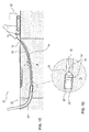
- a drilling rig 10 is shown for controlled drilling of a pilot bore.
- Drill rig 10 operates on a horizontal boring process, also referred to as Horizontal Directional Drilling (HDD).
- a horizontal drilling rig available under the trade name Terra-Jet is used for this purpose.
- Such a horizontal drilling rig is for example from the document DE 101 15 233 A1 known.
- a linkage 14 composed of a plurality of linkage sections 13 is introduced into the ground 18 in the direction of the arrow P0 by means of a horizontal boring device 12 at a starting point 16 with a drill head 20 arranged at the end of the linkage 14 remote from the horizontal boring device 12.
- the horizontal boring device 12 introduces flushing fluid into the hollow boom 14 at high pressure.
- the rinsing liquid exits the drill head 20 at high pressure. Due to the high pressure and hard metal teeth of the drill head 20, a borehole is cut into the ground 18.
- the drill head 20 is asymmetrically flattened at its front end and is continuously rotated by means of the rod 14 for producing a straight borehole. In a desired lateral movement, upward movement or downward movement of the drill head 20 is stopped in a suitable movement for this desired position and not rotated further, so that due to the asymmetrical flattened shape of the front end of the drill head 20, a corresponding deflection movement of the drill head 20 in the ground 18 takes place ,
- FIG. 1B shows a detail view of the end of the linkage 14 remote from the horizontal boring device 12 together with the boring head 20.
- an electronic probe is arranged, which can be located with the help of a corresponding locating device at any time from the earth's surface, so that the position of the drill head 20 in the ground 18 can be determined exactly at any time.
- the trajectory of the drill head 20, and thus the bore of the pilot bore is simply controlled by controlled stopping of the rotation of the drill head 20 via the linkage 14 so that the control surface of the drill head 20 is brought into a position required for the desired movement. Even after the targeted stopping of the rotation of the drill head 20 flushing fluid is further passed through the linkage 14 and the drill head 20 further driven by the linkage, so that the drilling operation of the desired course of the borehole is continued by means of the rinsing liquid and the propulsion of the drill head 20.
- HDPE pipes are made of high density polyethylene, this high density polyethylene being a high density thermoplastic so that the pipes made of HDPE have high toughness and rigidity, very good chemical resistance, good sliding properties, low density Moisture absorption, very good processing properties, are very good weldable and are physiologically harmless.
- tubes 26 may be drawn in from other materials, in particular metal.
- the horizontal drilling unit 12 generates the tensile force required for the expansion process on the linkage 14 and also passes rinsing fluid to the expansion head 24.
- the rinsing fluid supports at least the expansion of the pilot hole and also serves to drain and discharge the excess soil dissolved in the expansion process 18.
- At least part of the soil 18 contacted by the expansion tool 24 during the expansion process must be removed from the scree and rock. This can be done in particular by the annular gap between the already designated as a bore channel area of the pilot hole and the retracted tube 26 done.
- the rinsing fluid introduced into the annular gap also reduces the skin friction between the tube 26 and the drilling channel.
- the widening tool 24 has a centering region 25, which is arranged upstream relative to the widening region 31 of the widening tool 24 in the direction of movement of the widening tool 24 and substantially corresponds to the diameter of the widened opening.
- the expansion tool 24 has a large support surface via the centering region 25, via which a counterforce to the transverse forces acting on the widening region 31 transversely to the movement direction P1 can be provided.
- a deflection of the expansion tool 24 is effectively avoided in a simple manner, so that the pilot bore or a passage opening already present in the ground 18 can be widened centrally by means of the expansion tool 24 according to the invention.
- the new pipe 26 to be laid in this case an HDPE pipe, is used.
- two or more expansion tools 24 in succession up to a diameter of 1000 mm.
- tubes 26 are retracted to a diameter of 800 mm or a tube bundle of several tubes.
- a rinsing liquid water with Betonit or Ejactomer can be used.
- Such rinsing fluids stabilize the drill channel, reduce the friction between drill pipe 14 and soil 18 and the friction between the pipe 26 to be recovered and the soil 18. Further, 18 is conveyed out through the already partially retracted pipe 26 from the drilling channel using the rinsing liquid soil.
- FIG. 1D shows an enlarged section of the in Figure 1C In this section, the remote from the horizontal drilling 12 end of the linkage 14, the expansion head 24 and the already partially retracted into the ground 18 tube 26 are shown. If the drill head 20 or the expander head 24 is pulled too strongly against solid earth, rock or rock, then cutting of the drill head 20 or the expander head 24 can be pulled against the earth 18 with such a force that rotation of the drill head 20 or expander head 24 is not possible even with the producible with the horizontal boring machine 12 maximum torque. In order to prevent this, a limitation of the maximum feed force to a preset limit occurs in this embodiment.
- the feed force generated by a feed drive is preferably determined and compared with the preset limit value. The comparison is preferably carried out by a control unit, in particular a programmable logic controller (SPS) of the horizontal boring machine 12.
- SPS programmable logic controller
- the horizontal boring machine 12 preferably has a rotary drive for rotating the linkage 14 and the advancing drive for moving the linkage 14 along its longitudinal axis through the ground 18 together with the end of the linkage 14 remote from the advancing drive with the boring head 20 or expander head 24 connected thereto.
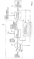
- FIG. 2 show a block diagram of a in a control unit 29 of the horizontal drilling 12 after the Fig.1A to 1D implemented control algorithm for controlling a feed drive of the drilling rig 10 and the horizontal drilling 12.
- the rotary drive is a hydraulic drive.
- a pressure sensor 34 With the aid of a pressure sensor 34, the pressure of the hydraulic fluid of the hydraulic drive supplied to the hydraulic fluid is determined. From this pressure can directly the driving force and the am Linkage 14 acting torque M is to be determined.
- the rotational speed of the linkage 14 can be determined with the aid of a corresponding rotational speed sensor 36 of the horizontal device 12. Is the actual value of the torque M a comparator 28 is supplied, which is this actual value M with a preset and stored in the control unit 29 of the horizontal drill 12 set value M soll.
- the comparator 28 determines a control deviation from the difference between the actual value Mist and the setpoint value M soll .
- the controller 30 outputs control signals for the feed rate and the feed force and, if necessary, changes the feed direction. These actuating signals are used as manipulated variables for controlling the feed drive.
- the feed force can be easily adjusted by the pressure of the hydraulic fluid supplied to the hydraulic drive and the feed rate by the amount of hydraulic fluid supplied to the feed drive.
- a hydraulic unit for providing the hydraulic fluid for the hydraulic drive is then given a predetermined pressure starting from the feed force predetermined by the controller 30 and starting from the feed rate predetermined by the controller 30 a flow, ie the amount of hydraulic fluid delivered by the hydraulic unit in a predetermined time.
- a maximum value for the feed force F max can also be preset.
- the controller 30 limits the setting signal of the feed force to this value F max .
- a further control loop for controlling the feed force can be provided when the controller 30 for controlling the torque outputs the preset maximum value F max of the feed force as a control signal. The other controller then ensures that the feed force is also in itself changing soil condition is kept constant at the preset maximum value of the feed force.
- the actual value of the torque M ist increases and exceeds the setpoint value M soll .
- the feed speed and the feed force are reduced. This is done relatively quickly, preferably in a period between 1 ms and 100 ms, to prevent the linkage 14 from being blocked and the drill head 20 and linkage 14 from being able to be further rotated. Also can be rotated by reducing the feed rate and the feed force a blocked linkage 14 again. Depending on the determined deviation of the actual value at the rise of the torque M is carried out a large reduction of the feed rate and the feed force, which then again slowly through the controller 30, for example over a period of 0.3 to 10 s is increased again.
- the increase and reduction of the feed force and feed rate can be carried out continuously and / or stepwise.
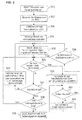
- FIG. 3 shows a flow chart for adjusting the feed force and feed rate when creating a pilot hole or when expanding a hole by means of the horizontal drilling rig 12.
- the process is started in step S10.
- a target value M soll of the torque is preset. This is done by an operator depending on the expected on the drilling distance composition and type of soil 18. For example, the target value M soll of the torque is preset to 80% of the maximum torque generated by the horizontal drilling rig 12.
- an operator a value for the maximum allowable feed force F max of the feed drive preset.
- the feed force must be used in particular for the expansion of a well bore and the simultaneous insertion of a new pipe 26, the pipe 26 through the widened opening in the ground 18 pull.
- the maximum feed force is preset as a starting value to, for example, 20% of the feed force that can be generated by means of the feed drive.
- Both the preset target value M soll of the torque and the value F max of the maximum permissible feed force can be changed at any time during operation of the horizontal boring device 12 by an operator if necessary.
- the steps S12 and S14 can also be exchanged or conventional setting values can already be preset in the control unit 29 so that they only have to be changed if necessary.
- the drilling operation is started, wherein the control unit 29 of the horizontal boring machine 12, the rotary drive for rotating the linkage 14 and the feed drive for generating a feed force to Activate feed of the linkage 14.
- the linkage with the arranged at the end of the linkage 14 drill head 20 is pressed into the soil during the manufacture of a pilot hole and in the expansion of a hole in the earth, the expansion head 24 connected to the linkage 14 is pulled by the feed force to the horizontal drill 12.
- step S18 the feed force and the feed speed are then slowly increased. Increasing the feed force and feed rate can be continuous or incremental. However, the feed force is increased only until the feed force has reached the preset maximum value F max .
- step S20 it is then checked in step S20 whether the actual value M ist of the torque, the is generated by the rotary drive for rotating the linkage 14 is greater than the preset target value M soll of the torque. If this is the case, it is then checked in step S22 whether the actual feed rate is less than the preset feed rate or whether the feed has stopped. If the feed rate is less than the predetermined feed rate or if the feed is stopped, then in step S24 the preset value F max of the maximum feed force is increased. This can be done by the control unit 29 stepwise automatically or by an operator. After increasing the maximum value of the feed force, the process proceeds to step S18 where the feed force and the feed speed are further increased.
- step S22 determines whether the feed has not stopped and the feed rate corresponds to the desired feed rate. If this is the case, the process is completed in step S28 and the horizontal drilling rig 12 can be switched off by an operator.
- step S20 If it is determined in step 26 that the drilling operation has not yet been completed, the process continues in step S20. If it is determined in step S20 that the actual value M ist of the torque is equal to or greater than the setpoint value M soll of the torque, then in step S30 the feed force and the feed speed are reduced relatively quickly. The reduction of the feed force and feed rate can be done gradually. After reducing the feed force and feed rate in step S30, it is checked in step S32 whether the linkage 14 is rotated by the rotary drive or whether the linkage 14 is blocked. If the linkage 14 is blocked, the feed drive then moves the linkage 14 in the opposite direction in step S34. For this purpose, in particular, a drill carriage of the feed drive engaging with the linkage 14 is moved counter to the drilling or expansion direction. Subsequently, the process proceeds to step S32.
- step S36 If it is determined in step S32 that the rotation of the linkage 14 is not blocked, that is, the linkage 14 rotates, it is checked in step S36, if the actual value Mist of the torque is smaller than a reduced by the amount x target value M soll-x is the torque. If this is the case, the process is continued in step S18 and the feed force and the feed rate are increased. If the actual value Mist of the torque does not fall below the setpoint value M soll-x of the torque reduced by the amount x, then the sequence is continued after step S36 with step S20.
- Increasing the feed force and feed rate in step S18 is slower than reducing the feed force and the feed rate in step S30.
- the feed force is reduced faster by a factor in the range of 2 to 100 in step S30 than increased in step S18.
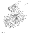
- FIG. 4 shows a perspective view of a horizontal auger 300 for producing and / or expansion of a well bore according to a second embodiment.
- the drilling apparatus 300 comprises two end plates 304, 306 delimiting a displacement unit 302, which are connected to one another via connecting elements 308, 310, 312, 314. About these connecting elements 308 to 314, the distance between the end plates 304, 306 is fixed.
- With the connecting elements 312, 314 support plates 316 to 322 are connected, via which the drill 300 can be supported in a pit or a shaft.
- the support plates 316 to 322 can be pulled out of the open ends of the connecting elements 314, 312 projecting through the end plates 304, 306 and via bolts 324, 326 in different extension stages connectable with the connecting elements 312, 314.
- the end plate 304 has a linkage passage 328, through which a linkage portion of the linkage 14 can be passed.
- Further locking levers 330, 332 are shown, by which a linkage portion of the linkage 14 can be optionally fixed so that it is prevented from rotating, so that the fixed linkage portion can be connected to another linkage section or can be separated from this further linkage section. Additionally or alternatively, by means of the clamping lever 330, 332 a displacement of a linkage section in the advancing direction P2 and opposite to the advancing direction can be prevented.
- a control panel 315 Connected to the connecting element 314 is a control panel 315, by means of which the displacement unit 302 and a hydraulic rotary drive 334 for generating a rotational movement of the boom receptacle 40 can be actuated.
- the rotary drive 334 is fixedly connected to the carriage 38.
- a transmission chain (not shown) arranged in the carriage 38 is provided.
- the displacement unit 302 has two cylinder assemblies 336, 338, which serve as a feed drive.
- the first cylinder assembly 336 has a first cylinder 340 with a first cylinder housing 342 and a first piston rod 344. Further, the first cylinder assembly 336 has a second cylinder 346 having a second cylinder housing 348 and a second piston rod 350.
- the second cylinder assembly 338 has a first cylinder 352 with a first cylinder housing 354 and a first piston rod 355. Further, the second cylinder assembly 338 includes a second cylinder, which in FIG. 4 is obscured by other elements.
- This second cylinder has a second cylinder housing and a second piston rod.
- One end of the piston rods 344, 356 is in each case with the first Face plate 304 firmly connected via a screw.
- the opposite second ends of the piston rods 344, 356 are screwed to the opposite second end plate 306, so that the piston rods 344, 356 serve as guide elements for guiding the displacement movement of the displacement unit 302.
- the face plate 304 facing side of the cylinder housing 342, 352 are connected via a first intermediate plate 364.
- the displacement unit 302 comprises a second intermediate plate 366, which is fixedly connected to the second end plate 306 facing the end of the cylinder housing 354, 342 of the first cylinder 340, 352 of the cylinder assemblies 336, 338. Furthermore, the ends of the piston rods 350, 362, which are fixedly connected to the first intermediate plate 364, are fixedly connected to the second intermediate plate 366 via a respective screw connection.
- the carriage 38 can also be displaced in the advancing direction P2 or in the opposite direction in the case of a displacement movement produced by the second cylinders 346, 358.
- the limiting of the feed force to a preset limit value F max is carried out in the horizontal drilling apparatus 300 in the same manner as in connection with the horizontal drilling apparatus 12 of the first embodiment in conjunction with the FIGS. 1 to 3 has been described.
- the horizontal drilling device 300 has a control unit 29.
- the feed drive for generating the feed motion of the drill string may also include a rack drive or other suitable drive.
Landscapes
- Life Sciences & Earth Sciences (AREA)
- Engineering & Computer Science (AREA)
- Geology (AREA)
- Mining & Mineral Resources (AREA)
- Physics & Mathematics (AREA)
- Environmental & Geological Engineering (AREA)
- Fluid Mechanics (AREA)
- General Life Sciences & Earth Sciences (AREA)
- Geochemistry & Mineralogy (AREA)
- Earth Drilling (AREA)
Priority Applications (1)
| Application Number | Priority Date | Filing Date | Title |
|---|---|---|---|
| PL16168005T PL3091173T3 (pl) | 2015-05-08 | 2016-05-03 | Urządzenie wiertnicze do wytwarzania lub poszerzania otworu w gruncie i sposób sterowania napędem posuwu takiego urządzenia wiertniczego |
Applications Claiming Priority (1)
| Application Number | Priority Date | Filing Date | Title |
|---|---|---|---|
| DE102015107194.0A DE102015107194A1 (de) | 2015-05-08 | 2015-05-08 | Bohranlage zum Erzeugen oder Aufweiten einer Erdbohrung im Erdreich und Verfahren zur Steuerung eines Vorschubantriebs einer solchen Bohranlage |
Publications (2)
| Publication Number | Publication Date |
|---|---|
| EP3091173A1 true EP3091173A1 (fr) | 2016-11-09 |
| EP3091173B1 EP3091173B1 (fr) | 2019-04-24 |
Family
ID=55910818
Family Applications (1)
| Application Number | Title | Priority Date | Filing Date |
|---|---|---|---|
| EP16168005.3A Active EP3091173B1 (fr) | 2015-05-08 | 2016-05-03 | Installation de forage déstinée à produire où à élargir un forage terrestre dans la terre et procédé de commande d'un dispositif d'avance d'une telle installation de forage |
Country Status (3)
| Country | Link |
|---|---|
| EP (1) | EP3091173B1 (fr) |
| DE (1) | DE102015107194A1 (fr) |
| PL (1) | PL3091173T3 (fr) |
Families Citing this family (3)
| Publication number | Priority date | Publication date | Assignee | Title |
|---|---|---|---|---|
| DE102018104020A1 (de) | 2018-02-22 | 2019-08-22 | TERRA AG für Tiefbautechnik | Vorrichtung zum Erzeugen oder Aufweiten einer Erdbohrung |
| DE102018113274A1 (de) | 2018-06-05 | 2019-12-19 | TERRA AG für Tiefbautechnik | Anordnung zum Erzeugen oder Aufweiten einer Erdbohrung im Erdreich |
| DE102018130065A1 (de) | 2018-11-28 | 2020-05-28 | TERRA AG für Tiefbautechnik | Adapteranordnung zum Verbinden eines Bohrwerkzeugs mit einem Bohrgestänge |
Citations (8)
| Publication number | Priority date | Publication date | Assignee | Title |
|---|---|---|---|---|
| EP0384888A1 (fr) * | 1989-02-23 | 1990-08-29 | SIG Schweizerische Industrie-Gesellschaft | Dispositif de forage |
| DE19708097A1 (de) | 1997-02-28 | 1998-09-03 | Krupp Werner & Pfleiderer Gmbh | Schnecken-Extrusionsvorrichtung, insbesondere Doppelschnecken-Extrusionsvorrichtung, zur Verarbeitung stark ausgasender Materialien |
| DE19708997A1 (de) | 1997-03-05 | 1998-09-17 | Terra Ag Tiefbautechnik | Verfahren und Vorrichtung zur Steuerung des Vorschubantriebes einer zum Erzeugen von Erdbohrungen bestimmten Bohranlage |
| US6189628B1 (en) | 1999-01-13 | 2001-02-20 | Terra Ag Fuer Tiefbautechnik | Earth borer system with drill-rod changer |
| DE10115233A1 (de) | 2000-05-11 | 2001-11-15 | Terra Ag Fuer Tiefbautechnik S | Horizontalbohranlage |
| DE10149018A1 (de) * | 2001-10-04 | 2003-05-08 | Tracto Technik | Verfahren zum Regeln der Vorschubkraft eines Bohrgeräts |
| DE102010004287A1 (de) | 2010-01-11 | 2011-07-14 | TERRA AG für Tiefbautechnik | Verfahren und Anordnung zum Herstellen und/oder Aufweiten einer Erdbohrung |
| EP2767672A2 (fr) * | 2013-02-19 | 2014-08-20 | PRAKLA Bohrtechnik GmbH | Dispositif de réalisation d'un forage dans le sol |
-
2015
- 2015-05-08 DE DE102015107194.0A patent/DE102015107194A1/de not_active Withdrawn
-
2016
- 2016-05-03 EP EP16168005.3A patent/EP3091173B1/fr active Active
- 2016-05-03 PL PL16168005T patent/PL3091173T3/pl unknown
Patent Citations (8)
| Publication number | Priority date | Publication date | Assignee | Title |
|---|---|---|---|---|
| EP0384888A1 (fr) * | 1989-02-23 | 1990-08-29 | SIG Schweizerische Industrie-Gesellschaft | Dispositif de forage |
| DE19708097A1 (de) | 1997-02-28 | 1998-09-03 | Krupp Werner & Pfleiderer Gmbh | Schnecken-Extrusionsvorrichtung, insbesondere Doppelschnecken-Extrusionsvorrichtung, zur Verarbeitung stark ausgasender Materialien |
| DE19708997A1 (de) | 1997-03-05 | 1998-09-17 | Terra Ag Tiefbautechnik | Verfahren und Vorrichtung zur Steuerung des Vorschubantriebes einer zum Erzeugen von Erdbohrungen bestimmten Bohranlage |
| US6189628B1 (en) | 1999-01-13 | 2001-02-20 | Terra Ag Fuer Tiefbautechnik | Earth borer system with drill-rod changer |
| DE10115233A1 (de) | 2000-05-11 | 2001-11-15 | Terra Ag Fuer Tiefbautechnik S | Horizontalbohranlage |
| DE10149018A1 (de) * | 2001-10-04 | 2003-05-08 | Tracto Technik | Verfahren zum Regeln der Vorschubkraft eines Bohrgeräts |
| DE102010004287A1 (de) | 2010-01-11 | 2011-07-14 | TERRA AG für Tiefbautechnik | Verfahren und Anordnung zum Herstellen und/oder Aufweiten einer Erdbohrung |
| EP2767672A2 (fr) * | 2013-02-19 | 2014-08-20 | PRAKLA Bohrtechnik GmbH | Dispositif de réalisation d'un forage dans le sol |
Also Published As
| Publication number | Publication date |
|---|---|
| EP3091173B1 (fr) | 2019-04-24 |
| PL3091173T3 (pl) | 2019-09-30 |
| DE102015107194A1 (de) | 2016-11-10 |
Similar Documents
| Publication | Publication Date | Title |
|---|---|---|
| EP2505762B1 (fr) | Dispositif de forage et procédé de forage horizontal | |
| EP2133507B1 (fr) | Dispositif et procédé de forage | |
| DE60218282T2 (de) | Aufweitvorrichtung | |
| EP0293584B1 (fr) | Dispositif de forage pour méthode de forage par injection à haute pression | |
| DE19708997C2 (de) | Vorrichtung zur Steuerung des Vorschubantriebes einer zum Erzeugen von Erdbohrungen bestimmten Bohranlage | |
| EP0548588B1 (fr) | Dispositif pour réaliser des forages dans le sol | |
| DE4035982A1 (de) | Gestaengerohr fuer einen bohrstrang | |
| EP2863003A2 (fr) | Outil et dispositif d'agrandissement d'un passage existant dans le sol | |
| EP3091173B1 (fr) | Installation de forage déstinée à produire où à élargir un forage terrestre dans la terre et procédé de commande d'un dispositif d'avance d'une telle installation de forage | |
| DE3421389C2 (fr) | ||
| CH704416A2 (de) | Bohranlage zum Durchführen von Bohrungen im Erdreich. | |
| EP2447462A1 (fr) | Procédé d'introduction souterraine d'une conduite | |
| EP2900895B1 (fr) | Dispositif et procédé de pose d'une canalisation dans un trou de forage | |
| EP1477633B1 (fr) | Procédé et dispositif pour le travail du sol | |
| EP3456914B1 (fr) | Dispositif de forage double tête et procédé de réalisation d'un forage | |
| EP3415708B1 (fr) | Dispositif de forage | |
| EP3940192B1 (fr) | Procédé de préparation ou de production un forage dans un sol | |
| EP0837190A2 (fr) | Dispositif et procédé pour la réalisation controlée de pieux et parois moulées dans le sol | |
| EP3112580B1 (fr) | Procédé et dispositif pour la formation d'une canalisation souterraine | |
| EP3530871B1 (fr) | Dispositif de production ou d'élargissement d'un forage de sol | |
| EP0705947B1 (fr) | Dispositif pour le remplacement des tuyaux, particulièrement des tuyaux d'égout | |
| EP1785580B1 (fr) | Procédé pour poser de tuyaux, élargisseur, dispositif de forage et tuyau | |
| EP4100611B1 (fr) | Dispositif de pose de tuyaux dans le sol | |
| DE102020127156B4 (de) | Vorrichtung zum Bohren einer horizontalen Bohrung | |
| DE19529554C2 (de) | Bohr- und/oder Injektionsvorrichtung |
Legal Events
| Date | Code | Title | Description |
|---|---|---|---|
| PUAI | Public reference made under article 153(3) epc to a published international application that has entered the european phase |
Free format text: ORIGINAL CODE: 0009012 |
|
| AK | Designated contracting states |
Kind code of ref document: A1 Designated state(s): AL AT BE BG CH CY CZ DE DK EE ES FI FR GB GR HR HU IE IS IT LI LT LU LV MC MK MT NL NO PL PT RO RS SE SI SK SM TR |
|
| AX | Request for extension of the european patent |
Extension state: BA ME |
|
| STAA | Information on the status of an ep patent application or granted ep patent |
Free format text: STATUS: REQUEST FOR EXAMINATION WAS MADE |
|
| 17P | Request for examination filed |
Effective date: 20170504 |
|
| RBV | Designated contracting states (corrected) |
Designated state(s): AL AT BE BG CH CY CZ DE DK EE ES FI FR GB GR HR HU IE IS IT LI LT LU LV MC MK MT NL NO PL PT RO RS SE SI SK SM TR |
|
| STAA | Information on the status of an ep patent application or granted ep patent |
Free format text: STATUS: EXAMINATION IS IN PROGRESS |
|
| 17Q | First examination report despatched |
Effective date: 20170925 |
|
| GRAP | Despatch of communication of intention to grant a patent |
Free format text: ORIGINAL CODE: EPIDOSNIGR1 |
|
| STAA | Information on the status of an ep patent application or granted ep patent |
Free format text: STATUS: GRANT OF PATENT IS INTENDED |
|
| INTG | Intention to grant announced |
Effective date: 20181115 |
|
| RIN1 | Information on inventor provided before grant (corrected) |
Inventor name: GRABER, ROMAN Inventor name: JENNE, DIETMAR |
|
| GRAS | Grant fee paid |
Free format text: ORIGINAL CODE: EPIDOSNIGR3 |
|
| GRAA | (expected) grant |
Free format text: ORIGINAL CODE: 0009210 |
|
| STAA | Information on the status of an ep patent application or granted ep patent |
Free format text: STATUS: THE PATENT HAS BEEN GRANTED |
|
| AK | Designated contracting states |
Kind code of ref document: B1 Designated state(s): AL AT BE BG CH CY CZ DE DK EE ES FI FR GB GR HR HU IE IS IT LI LT LU LV MC MK MT NL NO PL PT RO RS SE SI SK SM TR |
|
| REG | Reference to a national code |
Ref country code: GB Ref legal event code: FG4D Free format text: NOT ENGLISH |
|
| REG | Reference to a national code |
Ref country code: CH Ref legal event code: EP |
|
| REG | Reference to a national code |
Ref country code: AT Ref legal event code: REF Ref document number: 1124400 Country of ref document: AT Kind code of ref document: T Effective date: 20190515 Ref country code: IE Ref legal event code: FG4D Free format text: LANGUAGE OF EP DOCUMENT: GERMAN |
|
| REG | Reference to a national code |
Ref country code: DE Ref legal event code: R096 Ref document number: 502016004296 Country of ref document: DE |
|
| REG | Reference to a national code |
Ref country code: CH Ref legal event code: NV Representative=s name: SCHNEIDER FELDMANN AG PATENT- UND MARKENANWAEL, CH |
|
| REG | Reference to a national code |
Ref country code: NL Ref legal event code: MP Effective date: 20190424 |
|
| REG | Reference to a national code |
Ref country code: LT Ref legal event code: MG4D |
|
| PG25 | Lapsed in a contracting state [announced via postgrant information from national office to epo] |
Ref country code: NL Free format text: LAPSE BECAUSE OF FAILURE TO SUBMIT A TRANSLATION OF THE DESCRIPTION OR TO PAY THE FEE WITHIN THE PRESCRIBED TIME-LIMIT Effective date: 20190424 |
|
| PG25 | Lapsed in a contracting state [announced via postgrant information from national office to epo] |
Ref country code: SE Free format text: LAPSE BECAUSE OF FAILURE TO SUBMIT A TRANSLATION OF THE DESCRIPTION OR TO PAY THE FEE WITHIN THE PRESCRIBED TIME-LIMIT Effective date: 20190424 Ref country code: PT Free format text: LAPSE BECAUSE OF FAILURE TO SUBMIT A TRANSLATION OF THE DESCRIPTION OR TO PAY THE FEE WITHIN THE PRESCRIBED TIME-LIMIT Effective date: 20190824 Ref country code: AL Free format text: LAPSE BECAUSE OF FAILURE TO SUBMIT A TRANSLATION OF THE DESCRIPTION OR TO PAY THE FEE WITHIN THE PRESCRIBED TIME-LIMIT Effective date: 20190424 Ref country code: ES Free format text: LAPSE BECAUSE OF FAILURE TO SUBMIT A TRANSLATION OF THE DESCRIPTION OR TO PAY THE FEE WITHIN THE PRESCRIBED TIME-LIMIT Effective date: 20190424 Ref country code: LT Free format text: LAPSE BECAUSE OF FAILURE TO SUBMIT A TRANSLATION OF THE DESCRIPTION OR TO PAY THE FEE WITHIN THE PRESCRIBED TIME-LIMIT Effective date: 20190424 Ref country code: HR Free format text: LAPSE BECAUSE OF FAILURE TO SUBMIT A TRANSLATION OF THE DESCRIPTION OR TO PAY THE FEE WITHIN THE PRESCRIBED TIME-LIMIT Effective date: 20190424 Ref country code: NO Free format text: LAPSE BECAUSE OF FAILURE TO SUBMIT A TRANSLATION OF THE DESCRIPTION OR TO PAY THE FEE WITHIN THE PRESCRIBED TIME-LIMIT Effective date: 20190724 Ref country code: FI Free format text: LAPSE BECAUSE OF FAILURE TO SUBMIT A TRANSLATION OF THE DESCRIPTION OR TO PAY THE FEE WITHIN THE PRESCRIBED TIME-LIMIT Effective date: 20190424 |
|
| PG25 | Lapsed in a contracting state [announced via postgrant information from national office to epo] |
Ref country code: GR Free format text: LAPSE BECAUSE OF FAILURE TO SUBMIT A TRANSLATION OF THE DESCRIPTION OR TO PAY THE FEE WITHIN THE PRESCRIBED TIME-LIMIT Effective date: 20190725 Ref country code: LV Free format text: LAPSE BECAUSE OF FAILURE TO SUBMIT A TRANSLATION OF THE DESCRIPTION OR TO PAY THE FEE WITHIN THE PRESCRIBED TIME-LIMIT Effective date: 20190424 Ref country code: BG Free format text: LAPSE BECAUSE OF FAILURE TO SUBMIT A TRANSLATION OF THE DESCRIPTION OR TO PAY THE FEE WITHIN THE PRESCRIBED TIME-LIMIT Effective date: 20190724 Ref country code: RS Free format text: LAPSE BECAUSE OF FAILURE TO SUBMIT A TRANSLATION OF THE DESCRIPTION OR TO PAY THE FEE WITHIN THE PRESCRIBED TIME-LIMIT Effective date: 20190424 |
|
| PG25 | Lapsed in a contracting state [announced via postgrant information from national office to epo] |
Ref country code: IS Free format text: LAPSE BECAUSE OF FAILURE TO SUBMIT A TRANSLATION OF THE DESCRIPTION OR TO PAY THE FEE WITHIN THE PRESCRIBED TIME-LIMIT Effective date: 20190824 |
|
| REG | Reference to a national code |
Ref country code: DE Ref legal event code: R097 Ref document number: 502016004296 Country of ref document: DE |
|
| PG25 | Lapsed in a contracting state [announced via postgrant information from national office to epo] |
Ref country code: DK Free format text: LAPSE BECAUSE OF FAILURE TO SUBMIT A TRANSLATION OF THE DESCRIPTION OR TO PAY THE FEE WITHIN THE PRESCRIBED TIME-LIMIT Effective date: 20190424 Ref country code: MC Free format text: LAPSE BECAUSE OF FAILURE TO SUBMIT A TRANSLATION OF THE DESCRIPTION OR TO PAY THE FEE WITHIN THE PRESCRIBED TIME-LIMIT Effective date: 20190424 Ref country code: SK Free format text: LAPSE BECAUSE OF FAILURE TO SUBMIT A TRANSLATION OF THE DESCRIPTION OR TO PAY THE FEE WITHIN THE PRESCRIBED TIME-LIMIT Effective date: 20190424 Ref country code: EE Free format text: LAPSE BECAUSE OF FAILURE TO SUBMIT A TRANSLATION OF THE DESCRIPTION OR TO PAY THE FEE WITHIN THE PRESCRIBED TIME-LIMIT Effective date: 20190424 Ref country code: CZ Free format text: LAPSE BECAUSE OF FAILURE TO SUBMIT A TRANSLATION OF THE DESCRIPTION OR TO PAY THE FEE WITHIN THE PRESCRIBED TIME-LIMIT Effective date: 20190424 Ref country code: RO Free format text: LAPSE BECAUSE OF FAILURE TO SUBMIT A TRANSLATION OF THE DESCRIPTION OR TO PAY THE FEE WITHIN THE PRESCRIBED TIME-LIMIT Effective date: 20190424 |
|
| REG | Reference to a national code |
Ref country code: BE Ref legal event code: MM Effective date: 20190531 |
|
| PG25 | Lapsed in a contracting state [announced via postgrant information from national office to epo] |
Ref country code: IT Free format text: LAPSE BECAUSE OF FAILURE TO SUBMIT A TRANSLATION OF THE DESCRIPTION OR TO PAY THE FEE WITHIN THE PRESCRIBED TIME-LIMIT Effective date: 20190424 Ref country code: SM Free format text: LAPSE BECAUSE OF FAILURE TO SUBMIT A TRANSLATION OF THE DESCRIPTION OR TO PAY THE FEE WITHIN THE PRESCRIBED TIME-LIMIT Effective date: 20190424 Ref country code: LU Free format text: LAPSE BECAUSE OF NON-PAYMENT OF DUE FEES Effective date: 20190503 |
|
| PLBE | No opposition filed within time limit |
Free format text: ORIGINAL CODE: 0009261 |
|
| STAA | Information on the status of an ep patent application or granted ep patent |
Free format text: STATUS: NO OPPOSITION FILED WITHIN TIME LIMIT |
|
| PG25 | Lapsed in a contracting state [announced via postgrant information from national office to epo] |
Ref country code: TR Free format text: LAPSE BECAUSE OF FAILURE TO SUBMIT A TRANSLATION OF THE DESCRIPTION OR TO PAY THE FEE WITHIN THE PRESCRIBED TIME-LIMIT Effective date: 20190424 |
|
| 26N | No opposition filed |
Effective date: 20200127 |
|
| PG25 | Lapsed in a contracting state [announced via postgrant information from national office to epo] |
Ref country code: IE Free format text: LAPSE BECAUSE OF NON-PAYMENT OF DUE FEES Effective date: 20190503 |
|
| PG25 | Lapsed in a contracting state [announced via postgrant information from national office to epo] |
Ref country code: BE Free format text: LAPSE BECAUSE OF NON-PAYMENT OF DUE FEES Effective date: 20190531 Ref country code: SI Free format text: LAPSE BECAUSE OF FAILURE TO SUBMIT A TRANSLATION OF THE DESCRIPTION OR TO PAY THE FEE WITHIN THE PRESCRIBED TIME-LIMIT Effective date: 20190424 |
|
| REG | Reference to a national code |
Ref country code: CH Ref legal event code: PFA Owner name: TERRA AG FUER TIEFBAUTECHNIK, CH Free format text: FORMER OWNER: TERRA AG FUER TIEFBAUTECHNIK, CH |
|
| GBPC | Gb: european patent ceased through non-payment of renewal fee |
Effective date: 20200503 |
|
| PG25 | Lapsed in a contracting state [announced via postgrant information from national office to epo] |
Ref country code: GB Free format text: LAPSE BECAUSE OF NON-PAYMENT OF DUE FEES Effective date: 20200503 |
|
| PG25 | Lapsed in a contracting state [announced via postgrant information from national office to epo] |
Ref country code: CY Free format text: LAPSE BECAUSE OF FAILURE TO SUBMIT A TRANSLATION OF THE DESCRIPTION OR TO PAY THE FEE WITHIN THE PRESCRIBED TIME-LIMIT Effective date: 20190424 |
|
| PG25 | Lapsed in a contracting state [announced via postgrant information from national office to epo] |
Ref country code: MT Free format text: LAPSE BECAUSE OF FAILURE TO SUBMIT A TRANSLATION OF THE DESCRIPTION OR TO PAY THE FEE WITHIN THE PRESCRIBED TIME-LIMIT Effective date: 20190424 Ref country code: HU Free format text: LAPSE BECAUSE OF FAILURE TO SUBMIT A TRANSLATION OF THE DESCRIPTION OR TO PAY THE FEE WITHIN THE PRESCRIBED TIME-LIMIT; INVALID AB INITIO Effective date: 20160503 |
|
| PG25 | Lapsed in a contracting state [announced via postgrant information from national office to epo] |
Ref country code: MK Free format text: LAPSE BECAUSE OF FAILURE TO SUBMIT A TRANSLATION OF THE DESCRIPTION OR TO PAY THE FEE WITHIN THE PRESCRIBED TIME-LIMIT Effective date: 20190424 |
|
| REG | Reference to a national code |
Ref country code: AT Ref legal event code: MM01 Ref document number: 1124400 Country of ref document: AT Kind code of ref document: T Effective date: 20210503 |
|
| PG25 | Lapsed in a contracting state [announced via postgrant information from national office to epo] |
Ref country code: AT Free format text: LAPSE BECAUSE OF NON-PAYMENT OF DUE FEES Effective date: 20210503 |
|
| PGFP | Annual fee paid to national office [announced via postgrant information from national office to epo] |
Ref country code: PL Payment date: 20250423 Year of fee payment: 10 Ref country code: DE Payment date: 20250528 Year of fee payment: 10 |
|
| PGFP | Annual fee paid to national office [announced via postgrant information from national office to epo] |
Ref country code: FR Payment date: 20250523 Year of fee payment: 10 |
|
| PGFP | Annual fee paid to national office [announced via postgrant information from national office to epo] |
Ref country code: CH Payment date: 20250601 Year of fee payment: 10 |