EP3091679B1 - Procédé de transmission efficace de données dans un réseau de télécommunication optique en multiplexage de longueurs d'onde d'une pluralité de différentes longueurs d'ondes optiques, le réseau de télécommunication optique présentant deux n uds de réseau supérieurs et une pluralité d'éléments de réseau, réseau de télécommunication optique, programme informatique et produit de programme informatique - Google Patents
Procédé de transmission efficace de données dans un réseau de télécommunication optique en multiplexage de longueurs d'onde d'une pluralité de différentes longueurs d'ondes optiques, le réseau de télécommunication optique présentant deux n uds de réseau supérieurs et une pluralité d'éléments de réseau, réseau de télécommunication optique, programme informatique et produit de programme informatique Download PDFInfo
- Publication number
- EP3091679B1 EP3091679B1 EP16168009.5A EP16168009A EP3091679B1 EP 3091679 B1 EP3091679 B1 EP 3091679B1 EP 16168009 A EP16168009 A EP 16168009A EP 3091679 B1 EP3091679 B1 EP 3091679B1
- Authority
- EP
- European Patent Office
- Prior art keywords
- optical
- network node
- network
- signal path
- superordinate
- Prior art date
- Legal status (The legal status is an assumption and is not a legal conclusion. Google has not performed a legal analysis and makes no representation as to the accuracy of the status listed.)
- Active
Links
Images

Classifications
-
- H—ELECTRICITY
- H04—ELECTRIC COMMUNICATION TECHNIQUE
- H04J—MULTIPLEX COMMUNICATION
- H04J14/00—Optical multiplex systems
- H04J14/02—Wavelength-division multiplex systems
- H04J14/0287—Protection in WDM systems
Definitions
- the invention relates to a method for more effective data transmission in an optical telecommunications network in wavelength division multiplexing (WDM) of different optical wavelengths, wherein the optical telecommunication network has a first higher-level network node, a second higher-level network node and further a plurality of network elements ,
- WDM wavelength division multiplexing
- the invention further relates to an optical telecommunication network for more effective data transmission in an optical telecommunication network in wavelength-multiplexed operation of different optical wavelengths, wherein the optical telecommunication network has a first higher-level network node, a second higher-level network node and further a plurality of network elements.
- the invention also relates to a computer program with program code means and a computer program product with a computer-readable medium and a computer program stored on the computer-readable medium, which are suitable for carrying out all steps of the method according to the invention.
- optical telecommunication networks Methods for transmitting data using optical fibers, ie using optical telecommunication networks, are well known, for example EP 1 162 859 A2 .
- optical telecommunication networks are used, for example, in aggregation networks.
- Aggregation networks for example for private customer traffic, have the task of transporting traffic from regional nodes to backbone nodes.
- the backbone network in an A & B network structure - or with a duplicated structure - is operated.
- This has significant advantages from the point of view of the Internet protocol layer or Internet protocol layer, since both networks (or backbone networks) protect each other: behind a first higher-level network node (of the optical telecommunications network), for example, the A- ( Backbone) network and behind a second parent network node (of the optical telecommunications network) is the (back to A-backbone network) symmetrically constructed B (backbone) network.
- any (subordinate) network node of the optical telecommunications network is connected to both the first parent network node and the second parent network node.
- a run with the aim of the highest possible reliability operation of such aggregation network provides that at the same time in addition to the operationally used for data transmission part (between a data sending and a data receiving node) of the annular glass fiber route (working path) for the case of error
- the remainder of the ring-shaped fiber path (backup path) is used to transfer the data between the nodes involved.
- optical telecommunication network usually leads to a poor utilization of the available bandwidth of the aggregation network, in particular as soon as one uses optical interfaces (transponders, transceivers) with data rates adapted to the route length, so-called flex-rate transceivers.
- the invention has for its object to provide a method and an optical telecommunications network and a computer program and a computer program product, which optimally exploits the bandwidth resources and thus a higher under otherwise identical conditions - especially in terms of investment requirements for the components of the optical telecommunications network Performance (in the sense of an overall higher, usable data transport capacity) having at the same time not or only insignificantly reduced reliability against faults such as fiber breaks or the like.
- the optical telecommunication network has an annularly closed optical transmission path (ie in the form of an optical ring or a ring of a fiber optic line or fiber optic line), the optical telecommunication network having a first superordinate network node, a second superordinate network node and furthermore a plurality of network elements, wherein the plurality of network elements comprise at least a first network element and a second network element. Due to the ring closure, it is possible in an advantageous manner according to the invention that there is always a (not faulty) path for carrying out the data transmission between the respective source of the data and the respective destination of the data even in the event of a fault (ie, a fiber optic cable interrupted at one point) gives.
- a fault ie, a fiber optic cable interrupted at one point
- the optical ring is physically interrupted at each wavelength at one point, since otherwise a "laser" effect occurs in the ring equipped with amplifiers.
- This interruption can be realized, for example, with highly attenuating filters in reconfigurable optical add / drop nodes (ROADM, Reconfigurable Optical Add / Drop Multiplexers).
- the optical telecommunication network or the fiber optic ring typically has a multiplicity of network elements, which are also referred to as so-called R1 routers or (regional) aggregation nodes, and for a particular region, the connection of the network elements arranged below in the (network) hierarchy ensure the backbone network. Furthermore, the optical telecommunication network has the first higher-level network node and the second higher-level network node. These network nodes are also referred to as R2 routers or backbone routers.
- the backbone network in an A & B network structure - or with a doubled Structure - operated.
- both networks or backbone networks
- both networks or backbone networks to protect one another: behind a first higher-order network node (of the optical telecommunications network or the optical transmission link)
- a (backbone) network behind a second parent network node (the optical telecommunications network or the optical transmission path) is the (backbone) A (backbone) network symmetrically constructed (backbone) network.
- the backup path is hot during normal operation (ie it is already on the receiver), but is not evaluated in the error-free case. This guarantees that in the event of a fault, the backup signal does not have to be lengthened via the amplifier chain, but is present immediately and can be selected quickly with a switch. Especially in this respect, it does not matter whether transponders remote from the router are used or more novel, so-called "colored interfaces" are used directly in the router.
- the identical capacity allocation of several connections is an advantage for the traffic guidance, because the outbound flows from an R1 router are upstream (ie in the direction of an R1 router to the R2 router or to the R2 routers) by load balancing mechanisms symmetrically to the two connections or backbone networks (A-network or B-network) are divided and Downstream on a remote router, the traffic is distributed symmetrically.
- the Internet protocol layer Internet protocol layer
- Internet protocol layer can thus be operated completely independent of the topological routing in the optical transport network according to the conventional architecture.
- Both IP links can be operated with the same IP metric; Traffic engineering methods (eg ECMP, Equal Cost Multi Path) distribute the traffic load evenly across both interfaces, whereby the surviving link, for example, handles the entire load in the event of a fault, so that only a maximum of 50% of the load is loaded in a faultless case may. A healing of the error pattern thus takes place exclusively on the IP layer; the optical layer is not included in the restoration.
- Traffic engineering methods eg ECMP, Equal Cost Multi Path
- a disadvantage of such a conventional arrangement is that the two light paths often have to cover significantly different lengths of track in the ring. This means that often one of the two connections is operated far below its physical range limit, while the other connection already works just below the specified maximum range. This represents the normal case for non-range-adaptive interfaces (between the network elements or network nodes), so that a high degree of power reserve is lost in the case of a merely short connection between network elements or network nodes or remains unused in the conventional arrangement.
- transponders with flexible capacity does not lead to an increase in the data transmission capacity or the possible bandwidth in such a known system or such a known arrangement while maintaining the Disjunktheits brown (for the working path or the backup path).
- the interfaces may only be operated with up to 80% of the (nominal) available capacity.
- the background to this is short-term (in particular due to a given measurement interval of, for example, 100 seconds or 200 seconds or 300 seconds or 600 seconds) traffic peaks that can not be precisely measured, which are intercepted by the remaining 20% reserve.
- both connections must be operated symmetrically.
- this parallel operation also offers the possibility of offering or using the same data transmission capacities for both connections (ie both between the first higher-level network node and the considered network element and between the second higher-level network node and the considered network element) and, together with existing utilization rules ( predetermined upper limits in the normal case or non-error case) to enable a higher utilization of interfaces or interfaces.
- connection of an aggregation node (R1 router) to the two R2 backbone sites (or R2 router) (of the A network or the B network) is always at least partially via parallel connections.
- each optical network node element has at least one optical transponder and a multiplexer.
- a network node element which has a flexible data transmission capacity with respect to the reception of data via the optical transmission path or with respect to the transmission of data over the optical transmission path, designates such an optical network node element, which in particular has a transmission rate (in the transmission mode or in the transmission mode) in the receive mode) or its used modulation method has flexible transponder.
- the switching of the use of the data transport takes place within a time interval after the occurrence of the error case, wherein the time interval is less than or equal to or less than 100 milliseconds, preferably less than or equal to 50 milliseconds, more preferably less than or equal to maximum 30 milliseconds, most preferably less than a maximum of 10 milliseconds.
- the first nominal data transmission bandwidth over the first and / or further first signal path is used only up to a predetermined upper limit, wherein the predetermined upper limit is greater than or equal to 60%, preferably greater than or equal to 70%, more preferably greater than or equal to 80%, most preferably greater than or equal 90% of the first nominal data transmission bandwidth over the first and / or further first signal path.
- Typical is, for example, an operation of a telecommunication network with an optical transmission link such that normally only 80% of the nominally available data transmission bandwidth is utilized, i. Utilization of the nominal (i.e., technically) available transmission bandwidth is limited to 80% by normal operation rules so that there is the potential to deal with transient upward fluctuations in the transmission bandwidth required by the client layer without causing network congestion.
- the second nominal data transmission bandwidth is completely utilized via the second and / or further second signal path.
- the data transmission requests of the first network element ie from and to the first and / or second superordinate network node
- first type ie an error on the first subarea
- the present invention also relates to a computer program with program code means, by means of which all steps of the method according to the invention can be carried out when the computer program is executed on a programmable device and / or an optical network element and / or an optical network node element.
- the subject of the present invention is a computer program product with a computer-readable medium and a computer program stored on the computer-readable medium with program code means which are suitable for carrying out all steps of the method according to the invention if the computer program is on a programmable device and / or an optical network element and / or an optical network node element.
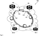
- FIG. 1 schematically is a view of an exemplary optical telecommunications network 100 and a closed annular optical transmission path 150 with a first parent network node R2, a second parent network node R2 'and with a first network element R1-1 and a second network element R1-2 shown.
- the first superordinate network node R2 has a first optical network node element 11 and the second superordinate network node R2 'has a second optical network node element 12. Furthermore, the first network element R1-1 has a third optical network node element 21 and the second network element R1-2 has a fourth optical network node element 22. It is preferably provided that the first, second, third and fourth optical network node elements 11, 12, 21, 22 each have a flexible data transmission capacity with respect to the reception of data via the optical transmission path 150 as well as with respect to the transmission of data over the optical transmission path 150 ,
- the schematically illustrated example of the arrangement of the superordinate network nodes R2, R2 'and the network elements R1-1, R1-2 shows that the path along the optical transmission path 150 between the first optical network node element 11 (or the first superordinate network node R2) and the third optical network node element 21 (or the first network element R1-1) via a first signal path 151 (ie via the in the pictorial representation of FIG FIG. 1 right side of the annularly closed optical transmission path 150) is shorter than via a second signal path 152 (ie over the left side of the annular closed optical transmission path 150 according to FIG FIG. 1 ).
- a first signal path 151 ie via the in the pictorial representation of FIG. 1 right side of the annularly closed optical transmission path 150
- second signal path 152 ie over the left side of the annular closed optical transmission path 150 according to FIG FIG. 1 .
- FIG. 2 schematically is a view of a conventional optical telecommunication network 100 'or an annular closed optical transmission path 150' with a first parent network node R2 ", a second parent network node R2 '” and with a first network element R1-1' and a second network element R1-2 'presented.
- the first higher-level network node R2 has a first optical network node element 11'
- the second higher-level network node R2 '" has a second optical network node element 12'.
- the first network element R1-1 ' has a third optical network node element 21'
- the second network element R1-2 ' has a fourth optical network node element 22'.
- the conventional telecommunications network 100 ' with regard to the highest possible reliability in the event of the use of a dual backbone network (ie in comparison to the higher-level network nodes of the considered optical telecommunication network (or optical ring), further superordinate network nodes are usually required) in the non-fault case, ie in the normal case, for example, the first network element R1-1 with the first parent network node R2 "via the third signal path 153 and the second parent network node R2 '" via the fourth signal path 154 is connected. If there then occurs an error on the path of the third signal path 153, the connection (of the first network element R1-1 ') to the second superordinate network node R2'"is not affected ..
- the first network element R1 -1 'in such an error case (ie, the error is on the third signal path 153) still be connected to the first parent network node R2 ".
- a further fourth signal path 154 ' is provided for the case when an error occurs on the fourth signal path 154.
- a higher data transmission bandwidth (first nominal data transmission bandwidth) than in a data transmission between these network node elements using the second or further second signal path 152, 152', on which (because of the greater path length on the optical transmission path 150) only a lower data transmission bandwidth is possible (second nominal data transmission bandwidth).
- these different physically possible data transmission bandwidths also take advantage in an advantageous manner, which represents a complete departure from the conventional operation of an optical telecommunications network, in which for reasons of higher reliability always disjoint routing for the data transport between a considered network element (ie either the first network element R1-1 (or the third network node element 21) or the second network element R1-2 (or the fourth network node element 22)) on the one hand and either the first higher-level network node R2 (or first network node element 11) or the second parent network node R2 '(or second network node element 12).
- a considered network element ie either the first network element R1-1 (or the third network node element 21) or the second network element R1-2 (or the fourth network node element 22)
- the present invention provides a solution to how data rate adaptive interfaces can be advantageously used in an Internet Protocol aggregation ring and operated particularly in the event of a line break (e.g., fiber breakage).
- a closed aggregation ring is advantageously combined with the use of so-called flex rate transponders (as part of the network node elements 11, 12, 21, 22).
- the term “FlexRate” denotes that the capacity of these interfaces or interfaces can be adapted electronically to the quality of the (optical) transmission path, in particular to the length of the optical transmission path, which is decisive for its quality.
- Significant cost savings can be achieved with the solution according to the invention.
- both connections have approximately the same route length (ie the first signal path 151 or the further first signal path 151 'in the case of data transmission between the first network element R1-1 and the first / second parent network node R2 / R2 ') and are also exposed to the same risk (which, however, can optically healed sufficiently quickly), they always offer the same (data transfer) capacity to the client layer.
- Load balancing i.e., balancing data transmission across different network paths
- the ring segment (the optical transmission path 150) between the two R2 routers can be considered to be very short, for example with realistic path lengths between 1 km and 20 km, more preferably between 4 km and 12km, for example within a large city, so that the distance or the route length between the two R2 routers with respect to the optical transmission path 150 can usually be neglected.
- optical protection mechanisms such as fast switches (such as MEMS-based (microelectromechanical system-based) switches), together with rapid adaptation within the data rate-flexible transponder, the backup light paths are activated within less than 50ms.
- An additional response to the Internet Protocol layer (the IP layer) is therefore not required.
- no protocol extensions for an interaction of different control layers (control plane interworking) of optical layer and Internet protocol layer are advantageously required.
- the existing Internet protocol metrics do not have to be recalculated and adapted in the event of an error situation.
Landscapes
- Engineering & Computer Science (AREA)
- Computer Networks & Wireless Communication (AREA)
- Signal Processing (AREA)
- Optical Communication System (AREA)
Claims (12)
- Réseau de télécommunication optique (100) destiné à la transmission de données plus efficace dans le mode en multiplexage de longueurs d'onde (WDM, wavelength division multiplex) de différentes longueurs d'onde optiques, le réseau de télécommunication optique (100) comportant un premier noeud de réseau supérieur (R2), un deuxième noeud de réseau supérieur (R2') et en outre une pluralité d'éléments de réseau (R1-1, R1-2), la pluralité d'éléments de réseau (R1-1, R1-2) comportant au moins un premier élément de réseau (R1-1) et un deuxième élément de réseau (R1-2), le réseau de télécommunication optique (100) comportant un circuit de transmission optique (150), le circuit de transmission optique (150) raccordant les uns aux autres, directement ou indirectement,- le premier noeud de réseau supérieur (R2) et le premier élément de réseau (R1-1) ainsi que- le premier élément de réseau (R1-1) et le deuxième élément de réseau (R1-2), de même qu'également- le deuxième élément de réseau (R1-2) et le deuxième noeud de réseau supérieur (R2'),le circuit de transmission optique (150) raccordant en outre également entre eux le premier noeud de réseau supérieur (R2) et le deuxième noeud de réseau supérieur (R2') de telle sorte que le circuit de transmission optique (150) est topologiquement fermé en forme d'anneau, le circuit de transmission optique (150) topologiquement fermé en forme d'anneau raccordant au moins indirectement le premier élément de réseau (R1-1) au premier noeud de réseau supérieur (R2) soit par le biais d'un premier chemin de signal (151), soit par le biais d'un deuxième chemin de signal (152), et le circuit de transmission optique (150) topologiquement fermé en forme d'anneau raccordant au moins indirectement le premier élément de réseau (R1-1) au deuxième noeud de réseau supérieur (R2') soit par le biais d'un autre premier chemin de signal (151'), soit par le biais d'un autre deuxième chemin de signal (152'), le premier chemin de signal (151) et l'autre premier chemin de signal (151') se chevauchant au moins dans une première zone partielle du circuit de transmission optique (150), le deuxième chemin de signal (152) et l'autre deuxième chemin de signal (152') se chevauchant au moins dans une deuxième zone partielle du circuit de transmission optique (150), le premier et le deuxième chemin de signal (151, 152) de même que l'autre autre premier et l'autre deuxième chemin de signal (151', 152') étant disjoints les uns des autres et se complétant pour former le circuit de transmission optique (150),
le réseau de télécommunication optique (100) étant configuré de telle sorte que, dans un mode de fonctionnement normal destiné à la transmission de données- entre le premier élément de réseau (R1-1) et le premier noeud de réseau supérieur (R2), le transport de données est utilisé sur le premier chemin de signal (151) du circuit de transmission optique (150) et- entre le premier élément de réseau (R1-1) et le deuxième noeud de réseau supérieur (R2'), le transport de données est utilisé sur l'autre premier chemin de signal (151') du circuit de transmission optique (150) (Dual Homing). - Réseau de télécommunication optique (100) selon la revendication 1, caractérisé en ce que le réseau de télécommunication optique (100) est configuré de telle sorte que, dans un mode de fonctionnement en cas de défaut dans lequel le circuit de transmission optique (150) est interrompu dans sa première zone partielle - du chevauchement entre le premier chemin de signal (151) et l'autre premier chemin de signal (151') - pour la transmission de données- entre le premier élément de réseau (R1-1) et le deuxième noeud de réseau supérieur (R2'), le transport de données est utilisé sur le deuxième chemin de signal (152) du circuit de transmission optique (150) et- entre le premier élément de réseau (R1-1) et le deuxième noeud de réseau supérieur (R2'), le transport de données est utilisé sur l'autre deuxième chemin de signal (152') du circuit de transmission optique (150),le réseau de télécommunication optique (100) étant en outre configuré de telle sorte qu'il y a une reconfiguration à partir du mode de fonctionnement normal vers le mode de fonctionnement en cas de défaut par une commutation du transport de données - à partir du premier et de l'autre premier chemin de signal (151, 151') vers le deuxième et l'autre deuxième chemin de signal (152, 152').
- Réseau de télécommunication optique (100) selon l'une des revendications précédentes, caractérisé en ce que le premier noeud de réseau supérieur (R2) comporte un premier élément de noeud de réseau optique (11), et le deuxième noeud de réseau supérieur (R2') comporte un deuxième élément de noeud de réseau optique (12), en ce que le premier élément de réseau (R1-1) comporte un troisième élément de noeud de réseau optique (21), et le deuxième élément de réseau (R1-2) comporte un quatrième élément de noeud de réseau optique (22), le premier, deuxième, troisième et quatrième élément de noeud de réseau optique (11, 12, 21, 22) comportant respectivement une capacité flexible de transmission de données en ce qui concerne la réception de données par le biais du circuit de transmission optique (150) ainsi qu'en ce qui concerne l'émission de données par le biais du circuit de transmission optique (150), le premier, deuxième, troisième et quatrième élément de noeud de réseau optique (11, 12, 21, 22) étant constitués respectivement en tant que multiplexeur insertion-extraction optique (OADM, optical add drop multiplexer), en particulier en tant que multiplexeur insertion-extraction reconfigurable (ROADM, reconfigurable optical add drop multiplexer), en particulier une transmission de données au moyen du circuit de transmission optique (150)- entre le premier élément de noeud de réseau optique (11) et le troisième élément de noeud de réseau optique (21), ou- entre le deuxième élément de noeud de réseau optique (12) et le troisième élément de noeud de réseau optique (21)étant possible au moyen du premier et/ou de l'autre premier chemin de signal (151, 151') avec une première largeur de bande de transmission de données nominale plus élevée, tandis qu'une telle transmission de données au moyen du deuxième et/ou de l'autre deuxième chemin de signal (151') n'est possible qu'avec une deuxième largeur de bande de transmission de données nominale plus faible.
- Procédé destiné à la transmission de données plus efficace dans le mode en multiplexage de longueurs d'onde (WDM, wavelength division multiplex) de différentes longueurs d'onde optiques, le réseau de télécommunication optique (100) comportant un premier noeud de réseau supérieur (R2), un deuxième noeud de réseau supérieur (R2') et en outre une pluralité d'éléments de réseau (R1-1, R1-2), la pluralité d'éléments de réseau (R1-1, R1-2) comportant au moins un premier élément de réseau (R1-1) et un deuxième élément de réseau (R1-2), le réseau de télécommunication optique (100) comportant un circuit de transmission optique (150), le circuit de transmission optique (150) raccordant les uns aux autres, directement ou indirectement,- le premier noeud de réseau supérieur (R2) et le premier élément de réseau (R1-1) ainsi que- le premier élément de réseau (R1-1) et le deuxième élément de réseau (R1-2), de même qu'également- le deuxième élément de réseau (R1-2) et le deuxième noeud de réseau supérieur (R2'),le circuit de transmission optique (150) raccordant en outre également entre eux le premier noeud de réseau supérieur (R2) et le deuxième noeud de réseau supérieur (R2') de telle sorte que le circuit de transmission optique (150) est topologiquement fermé en forme d'anneau, le circuit de transmission optique (150) topologiquement fermé en forme d'anneau raccordant au moins indirectement le premier élément de réseau (R1-1) au premier noeud de réseau supérieur (R2) soit par le biais d'un premier chemin de signal (151), soit par le biais d'un deuxième chemin de signal (152), et le circuit de transmission optique (150) topologiquement fermé en forme d'anneau raccordant au moins indirectement le premier élément de réseau (R1-1) au deuxième noeud de réseau supérieur (R2') soit par le biais d'un autre premier chemin de signal (151'), soit par le biais d'un autre deuxième chemin de signal (152'), le premier chemin de signal (151) et l'autre premier chemin de signal (151') se chevauchant au moins dans une première zone partielle du circuit de transmission optique (150), le deuxième chemin de signal (152) et l'autre deuxième chemin de signal (152') se chevauchant au moins dans une deuxième zone partielle du circuit de transmission optique (150), le premier et le deuxième chemin de signal (151, 152) de même que l'autre autre premier et l'autre deuxième chemin de signal (151', 152') étant disjoints les uns des autres et se complétant respectivement par paires pour former le circuit de transmission optique (150),
dans lequel, dans un mode de fonctionnement normal du réseau de télécommunication optique (100), pour la transmission de données- entre le premier élément de réseau (R1-1) et le premier noeud de réseau supérieur (R2), le transport de données est utilisé sur le premier chemin de signal (151) du circuit de transmission optique (150) et- entre le premier élément de réseau (R1-1) et le deuxième noeud de réseau supérieur (R2'), le transport de données est utilisé sur l'autre premier chemin de signal (151') du circuit de transmission optique (150) (Dual Homing). - Procédé selon la revendication 4, caractérisé en ce que, dans un mode de fonctionnement en cas de défaut dans lequel le circuit de transmission optique (150) est interrompu dans sa première zone partielle - du chevauchement entre le premier chemin de signal (151) et l'autre premier chemin de signal (151') - pour la transmission de données- entre le premier élément de réseau (R1-1) et le premier noeud de réseau supérieur (R2), le transport de données est utilisé sur le deuxième chemin de signal (152) du circuit de transmission optique (150) et- entre le premier élément de réseau (R1-1) et le premier noeud de réseau supérieur (R2), le transport de données est utilisé sur l'autre deuxième chemin de signal (152') du circuit de transmission optique (150),dans lequel il y a une reconfiguration à partir du mode de fonctionnement normal vers le mode de fonctionnement en cas de défaut par une commutation du transport de données - à partir du premier et de l'autre premier chemin de signal (151, 151') vers le deuxième et l'autre deuxième chemin de signal (152, 152').
- Procédé selon l'une des revendications 4 ou 5, caractérisé en ce que le premier noeud de réseau supérieur (R2) comporte un premier élément de noeud de réseau optique (11), et le deuxième noeud de réseau supérieur (R2') comporte un deuxième élément de noeud de réseau optique (12), en ce que le premier élément de réseau (R1-1) comporte un troisième élément de noeud de réseau optique (21), et le deuxième élément de réseau (R1-2) comporte un quatrième élément de noeud de réseau optique (22), le premier, deuxième, troisième et quatrième élément de noeud de réseau optique (11, 12, 21, 22) comportant respectivement une capacité flexible de transmission de données en ce qui concerne la réception de données par le biais du circuit de transmission optique (150) ainsi qu'en ce qui concerne l'émission de données par le biais du circuit de transmission optique (150), une transmission de données au moyen du circuit de transmission optique (150)- entre le premier élément de noeud de réseau optique (11) et le troisième élément de noeud de réseau optique (21), ou- entre le deuxième élément de noeud de réseau optique (12) et le troisième élément de noeud de réseau optique (21)étant possible au moyen du premier et/ou de l'autre premier chemin de signal (151, 151') avec une première largeur de bande de transmission de données nominale plus élevée, tandis qu'une telle transmission de données au moyen du deuxième et/ou de l'autre deuxième chemin de signal (151') n'est possible qu'avec une deuxième largeur de bande de transmission de données nominale plus faible.
- Procédé selon l'une des revendications 4 à 6, caractérisé en ce que la commutation de l'utilisation du transport de données s'effectue à l'intérieur d'un intervalle de temps après la survenue du cas de défaut, l'intervalle de temps ne dépassant pas au maximum 100 millisecondes, de préférence ne dépassant pas au maximum 50 millisecondes, particulièrement préférablement ne dépassant pas au maximum 30 millisecondes.
- Procédé selon l'une des revendications 4 à 7, caractérisé en ce que, dans le mode de fonctionnement normal du réseau de télécommunication optique (100) - et dans un mode de fonctionnement en cas de défaut du réseau de télécommunication optique (100) dans lequel le circuit de transmission optique (150) est interrompu dans sa première zone partielle - du chevauchement entre le premier chemin de signal (151) et l'autre premier chemin de signal (151'),- pour la transmission de données entre le deuxième élément de réseau (R1-2) d'un côté et- aussi bien entre le premier noeud de réseau supérieur (R2) qu'entre le deuxième noeud de réseau supérieur (R2') de l'autre côté, le transport de données est utilisé sur une zone partielle du deuxième et/ou de l'autre autre deuxième chemin de signal (152, 152') du circuit de transmission optique (150).
- Procédé selon l'une des revendications 4 à 8, caractérisé en ce que, dans le mode de fonctionnement normal, la première largeur de bande de transmission de données nominale par le biais du premier et/ou de l'autre premier chemin de signal (151, 151') n'est utilisée que jusqu'à une limite supérieure prédéfinie, la limite supérieure prédéfinie étant supérieure ou égale à 60 %, de préférence supérieure ou égale à 70 %, de façon particulièrement préférée supérieure ou égale à 80 %, de façon tout à fait particulièrement préférée supérieure ou égale à 90 % de la première largeur de bande de transmission de données nominale par le biais du premier et/ou de l'autre premier chemin de signal (151, 151').
- Procédé selon l'une des revendications 4 à 9, caractérisé en ce que, dans le mode de fonctionnement en cas de défaut, la deuxième largeur de bande de transmission de données nominale par le biais du deuxième et/ou de l'autre deuxième chemin de signal (152, 152') est utilisée complètement.
- Programme informatique avec des moyens de code de programme, à l'aide desquels toutes les étapes d'un procédé selon l'une des revendications 4 à 10 peuvent être réalisées quand le programme informatique est exécuté sur plusieurs éléments de noeud de réseau optiques (11, 12, 21, 22).
- Produit de programme informatique avec un support lisible par ordinateur et un programme informatique stocké sur le support lisible par ordinateur, avec des moyens de code de programme qui sont appropriés pour que toutes les étapes d'un procédé selon l'une des revendications 4 à 10 puissent être réalisées quand le programme informatique est exécuté sur plusieurs éléments de noeud de réseau optiques (11, 12, 21, 22).
Priority Applications (1)
| Application Number | Priority Date | Filing Date | Title |
|---|---|---|---|
| HRP20190899TT HRP20190899T1 (hr) | 2015-05-05 | 2019-05-15 | Metoda za učinkovitiji prijenos podataka u optičkoj telekomunikacijskoj mreži u višestrukoj operaciji optičkih valnih duljina, pri čemu optička telekomunikacijska mreža ima mnoštvo mrežnih elemenata i dva nadređena mrežna čvora, optička telekomunikacijska mreža, računalni program i proizvod računaln |
Applications Claiming Priority (1)
| Application Number | Priority Date | Filing Date | Title |
|---|---|---|---|
| DE102015208329.2A DE102015208329B3 (de) | 2015-05-05 | 2015-05-05 | Verfahren zur effektiveren Datenübertragung in einem optischen Telekommunikationsnetz im Wellenlängen-Multiplex-Betrieb von verschiedenen optischen Wellenlängen, wobei das optische Telekommunikationsnetz zwei übergeordnete Netzknoten und eine Mehrzahl von Netzelementen aufweist, optisches Telekommunikationsnetz, Computerprogramm und Computerprogrammprodukt |
Publications (2)
| Publication Number | Publication Date |
|---|---|
| EP3091679A1 EP3091679A1 (fr) | 2016-11-09 |
| EP3091679B1 true EP3091679B1 (fr) | 2019-02-27 |
Family
ID=55913495
Family Applications (1)
| Application Number | Title | Priority Date | Filing Date |
|---|---|---|---|
| EP16168009.5A Active EP3091679B1 (fr) | 2015-05-05 | 2016-05-03 | Procédé de transmission efficace de données dans un réseau de télécommunication optique en multiplexage de longueurs d'onde d'une pluralité de différentes longueurs d'ondes optiques, le réseau de télécommunication optique présentant deux n uds de réseau supérieurs et une pluralité d'éléments de réseau, réseau de télécommunication optique, programme informatique et produit de programme informatique |
Country Status (4)
| Country | Link |
|---|---|
| EP (1) | EP3091679B1 (fr) |
| DE (1) | DE102015208329B3 (fr) |
| HR (1) | HRP20190899T1 (fr) |
| HU (1) | HUE044894T2 (fr) |
Families Citing this family (1)
| Publication number | Priority date | Publication date | Assignee | Title |
|---|---|---|---|---|
| ES2757911T3 (es) * | 2016-12-29 | 2020-04-30 | Deutsche Telekom Ag | Transmisión de datos en una red IP con múltiples niveles de red central |
Family Cites Families (3)
| Publication number | Priority date | Publication date | Assignee | Title |
|---|---|---|---|---|
| GB2350001B (en) * | 1999-05-13 | 2004-06-09 | Fujitsu Ltd | Optical networks |
| US7342873B1 (en) * | 2000-06-06 | 2008-03-11 | Lucent Technologies Inc. | Efficient architectures for protection against network failures |
| US7072584B1 (en) * | 2002-04-22 | 2006-07-04 | Atrica Israel Ltd. | Network hub employing 1:N optical protection |
-
2015
- 2015-05-05 DE DE102015208329.2A patent/DE102015208329B3/de not_active Expired - Fee Related
-
2016
- 2016-05-03 EP EP16168009.5A patent/EP3091679B1/fr active Active
- 2016-05-03 HU HUE16168009 patent/HUE044894T2/hu unknown
-
2019
- 2019-05-15 HR HRP20190899TT patent/HRP20190899T1/hr unknown
Non-Patent Citations (1)
| Title |
|---|
| None * |
Also Published As
| Publication number | Publication date |
|---|---|
| EP3091679A1 (fr) | 2016-11-09 |
| HRP20190899T1 (hr) | 2019-08-23 |
| DE102015208329B3 (de) | 2016-10-06 |
| HUE044894T2 (hu) | 2019-11-28 |
Similar Documents
| Publication | Publication Date | Title |
|---|---|---|
| EP2859676B1 (fr) | Procédé et dispositif pour l'établissement et le fonctionnement d'un réseau modulaire, hautement évolutif, très simple, économique, durable, transparent et à transmission optique pour des capacités de réseau supérieures à 1 pétabit | |
| DE69323189T2 (de) | Optisches informationsverarbeitungssystem | |
| EP2145413B1 (fr) | Procédé de protection d'un réseau de transmission optique passif et réseau de transmission optique passif comprenant un mécanisme de protection correspondant | |
| DE69531594T2 (de) | Kommunikationsnetzwerk mit Ringstruktur über einen optischen Träger und rekonfigurierbarer Knoten für diese Struktur | |
| DE60118654T2 (de) | Optischer Netzwerkknoten | |
| DE69933559T2 (de) | Optisches wdm netzwerk mit effizientem gebrauch der wellenlänge und knoten dafür verwendeter | |
| DE69634611T2 (de) | Selbstheilendes netzwerk | |
| DE69605542T2 (de) | Optische mehrkanalanordnung | |
| DE69820609T2 (de) | Optische einfugungs/ausblendungsvorrichtung | |
| WO1999005811A1 (fr) | Procede et dispositif pour transmettre des donnees selon un procede de multiplexage en longueur d'onde dans un reseau annulaire optique | |
| DE60125638T2 (de) | Effiziente Architektur zum Netzwerkfehlerschutz | |
| DE69918805T2 (de) | Optisches telekommunikationsnetzwerk | |
| EP2940911B1 (fr) | Réseau de transmission optique et éléments de réseau optique destinés à la transmissions de signaux WDM | |
| DE102015208329B3 (de) | Verfahren zur effektiveren Datenübertragung in einem optischen Telekommunikationsnetz im Wellenlängen-Multiplex-Betrieb von verschiedenen optischen Wellenlängen, wobei das optische Telekommunikationsnetz zwei übergeordnete Netzknoten und eine Mehrzahl von Netzelementen aufweist, optisches Telekommunikationsnetz, Computerprogramm und Computerprogrammprodukt | |
| EP4007293A1 (fr) | Flexibilisation des réseaux de communication optique | |
| EP3179649B1 (fr) | Procede et systeme de transmission efficace de donnees dans un reseau de telecommunication optique en multiplexage | |
| DE102016207857B4 (de) | Verfahren zur effizienteren Datenübertragung in einem optischen Telekommunikationsnetz im Wellenlängen-Multiplex-Betrieb (WDM) von verschiedenen optischen Wellenlängen, wobei das optische Telekommunikationsnetz einen ersten übergeordneten Netzknoten, einen zweiten übergeordneten Netzknoten und ferner eine Mehrzahl von Netzelementen aufweist, optisches Telekommunikationsnetz, Computerprogramm und Computerprogrammprodukt | |
| EP1097540A1 (fr) | Procede et dispositif pour optimiser la securite de transmission et la tolerance aux defauts dans des reseaux de donnees a debit binaire eleve | |
| EP3169011A1 (fr) | Procédé de dimensionnement de réseaux optiques sans filtre | |
| EP3247062B1 (fr) | Procédé de transmission efficace de données dans un réseau de télécommunication en particulier basé sur des composants de transmission de données optiques en multiplexage en longueurs d'onde d'une pluralité de différentes longueurs d'ondes optiques, le réseau de télécommunication optique comprenant une pluralité de n uds de réseau et de lignes de transmission de données présentes entre les n uds de réseau, réseau de télécommunication, programme informatique et produit de programme informatique | |
| DE102013110784A1 (de) | Dienstsensibles flexibles ipowdm-netz und betriebsverfahren | |
| DE69913488T2 (de) | Kommunikationssystem mit Stern/Ring Topologie | |
| DE69820020T2 (de) | Vorrichtung und verfahren zum wiederherstellen von netzwerkverbindungen für faseroptische nachrichtenübertragung | |
| DE69835579T2 (de) | Verfahren und Vorrichtung für optisch transparente Übertragung in einem bidirektionalen Ringnetz mit zwei Fasern, Selbstschutz und Niederprioritätsverwaltung | |
| EP3343816B1 (fr) | Transfert de données dans un réseau ip ayant plusieurs niveaux de réseau central |
Legal Events
| Date | Code | Title | Description |
|---|---|---|---|
| PUAI | Public reference made under article 153(3) epc to a published international application that has entered the european phase |
Free format text: ORIGINAL CODE: 0009012 |
|
| AK | Designated contracting states |
Kind code of ref document: A1 Designated state(s): AL AT BE BG CH CY CZ DE DK EE ES FI FR GB GR HR HU IE IS IT LI LT LU LV MC MK MT NL NO PL PT RO RS SE SI SK SM TR |
|
| AX | Request for extension of the european patent |
Extension state: BA ME |
|
| STAA | Information on the status of an ep patent application or granted ep patent |
Free format text: STATUS: REQUEST FOR EXAMINATION WAS MADE |
|
| 17P | Request for examination filed |
Effective date: 20170111 |
|
| RBV | Designated contracting states (corrected) |
Designated state(s): AL AT BE BG CH CY CZ DE DK EE ES FI FR GB GR HR HU IE IS IT LI LT LU LV MC MK MT NL NO PL PT RO RS SE SI SK SM TR |
|
| GRAP | Despatch of communication of intention to grant a patent |
Free format text: ORIGINAL CODE: EPIDOSNIGR1 |
|
| STAA | Information on the status of an ep patent application or granted ep patent |
Free format text: STATUS: GRANT OF PATENT IS INTENDED |
|
| INTG | Intention to grant announced |
Effective date: 20181010 |
|
| GRAS | Grant fee paid |
Free format text: ORIGINAL CODE: EPIDOSNIGR3 |
|
| GRAA | (expected) grant |
Free format text: ORIGINAL CODE: 0009210 |
|
| STAA | Information on the status of an ep patent application or granted ep patent |
Free format text: STATUS: THE PATENT HAS BEEN GRANTED |
|
| AK | Designated contracting states |
Kind code of ref document: B1 Designated state(s): AL AT BE BG CH CY CZ DE DK EE ES FI FR GB GR HR HU IE IS IT LI LT LU LV MC MK MT NL NO PL PT RO RS SE SI SK SM TR |
|
| REG | Reference to a national code |
Ref country code: GB Ref legal event code: FG4D Free format text: NOT ENGLISH |
|
| REG | Reference to a national code |
Ref country code: CH Ref legal event code: EP |
|
| REG | Reference to a national code |
Ref country code: AT Ref legal event code: REF Ref document number: 1102873 Country of ref document: AT Kind code of ref document: T Effective date: 20190315 |
|
| REG | Reference to a national code |
Ref country code: IE Ref legal event code: FG4D Free format text: LANGUAGE OF EP DOCUMENT: GERMAN |
|
| REG | Reference to a national code |
Ref country code: DE Ref legal event code: R096 Ref document number: 502016003496 Country of ref document: DE |
|
| REG | Reference to a national code |
Ref country code: HR Ref legal event code: TUEP Ref document number: P20190899 Country of ref document: HR |
|
| REG | Reference to a national code |
Ref country code: HR Ref legal event code: ODRP Ref document number: P20190899 Country of ref document: HR Payment date: 20190520 Year of fee payment: 4 |
|
| REG | Reference to a national code |
Ref country code: NL Ref legal event code: MP Effective date: 20190227 |
|
| REG | Reference to a national code |
Ref country code: LT Ref legal event code: MG4D |
|
| PG25 | Lapsed in a contracting state [announced via postgrant information from national office to epo] |
Ref country code: FI Free format text: LAPSE BECAUSE OF FAILURE TO SUBMIT A TRANSLATION OF THE DESCRIPTION OR TO PAY THE FEE WITHIN THE PRESCRIBED TIME-LIMIT Effective date: 20190227 Ref country code: LT Free format text: LAPSE BECAUSE OF FAILURE TO SUBMIT A TRANSLATION OF THE DESCRIPTION OR TO PAY THE FEE WITHIN THE PRESCRIBED TIME-LIMIT Effective date: 20190227 Ref country code: SE Free format text: LAPSE BECAUSE OF FAILURE TO SUBMIT A TRANSLATION OF THE DESCRIPTION OR TO PAY THE FEE WITHIN THE PRESCRIBED TIME-LIMIT Effective date: 20190227 Ref country code: NO Free format text: LAPSE BECAUSE OF FAILURE TO SUBMIT A TRANSLATION OF THE DESCRIPTION OR TO PAY THE FEE WITHIN THE PRESCRIBED TIME-LIMIT Effective date: 20190527 Ref country code: PT Free format text: LAPSE BECAUSE OF FAILURE TO SUBMIT A TRANSLATION OF THE DESCRIPTION OR TO PAY THE FEE WITHIN THE PRESCRIBED TIME-LIMIT Effective date: 20190627 Ref country code: NL Free format text: LAPSE BECAUSE OF FAILURE TO SUBMIT A TRANSLATION OF THE DESCRIPTION OR TO PAY THE FEE WITHIN THE PRESCRIBED TIME-LIMIT Effective date: 20190227 |
|
| REG | Reference to a national code |
Ref country code: HR Ref legal event code: T1PR Ref document number: P20190899 Country of ref document: HR |
|
| PG25 | Lapsed in a contracting state [announced via postgrant information from national office to epo] |
Ref country code: GR Free format text: LAPSE BECAUSE OF FAILURE TO SUBMIT A TRANSLATION OF THE DESCRIPTION OR TO PAY THE FEE WITHIN THE PRESCRIBED TIME-LIMIT Effective date: 20190528 Ref country code: BG Free format text: LAPSE BECAUSE OF FAILURE TO SUBMIT A TRANSLATION OF THE DESCRIPTION OR TO PAY THE FEE WITHIN THE PRESCRIBED TIME-LIMIT Effective date: 20190527 Ref country code: RS Free format text: LAPSE BECAUSE OF FAILURE TO SUBMIT A TRANSLATION OF THE DESCRIPTION OR TO PAY THE FEE WITHIN THE PRESCRIBED TIME-LIMIT Effective date: 20190227 Ref country code: IS Free format text: LAPSE BECAUSE OF FAILURE TO SUBMIT A TRANSLATION OF THE DESCRIPTION OR TO PAY THE FEE WITHIN THE PRESCRIBED TIME-LIMIT Effective date: 20190627 Ref country code: LV Free format text: LAPSE BECAUSE OF FAILURE TO SUBMIT A TRANSLATION OF THE DESCRIPTION OR TO PAY THE FEE WITHIN THE PRESCRIBED TIME-LIMIT Effective date: 20190227 |
|
| PG25 | Lapsed in a contracting state [announced via postgrant information from national office to epo] |
Ref country code: AL Free format text: LAPSE BECAUSE OF FAILURE TO SUBMIT A TRANSLATION OF THE DESCRIPTION OR TO PAY THE FEE WITHIN THE PRESCRIBED TIME-LIMIT Effective date: 20190227 Ref country code: EE Free format text: LAPSE BECAUSE OF FAILURE TO SUBMIT A TRANSLATION OF THE DESCRIPTION OR TO PAY THE FEE WITHIN THE PRESCRIBED TIME-LIMIT Effective date: 20190227 Ref country code: DK Free format text: LAPSE BECAUSE OF FAILURE TO SUBMIT A TRANSLATION OF THE DESCRIPTION OR TO PAY THE FEE WITHIN THE PRESCRIBED TIME-LIMIT Effective date: 20190227 Ref country code: SK Free format text: LAPSE BECAUSE OF FAILURE TO SUBMIT A TRANSLATION OF THE DESCRIPTION OR TO PAY THE FEE WITHIN THE PRESCRIBED TIME-LIMIT Effective date: 20190227 Ref country code: RO Free format text: LAPSE BECAUSE OF FAILURE TO SUBMIT A TRANSLATION OF THE DESCRIPTION OR TO PAY THE FEE WITHIN THE PRESCRIBED TIME-LIMIT Effective date: 20190227 Ref country code: IT Free format text: LAPSE BECAUSE OF FAILURE TO SUBMIT A TRANSLATION OF THE DESCRIPTION OR TO PAY THE FEE WITHIN THE PRESCRIBED TIME-LIMIT Effective date: 20190227 Ref country code: CZ Free format text: LAPSE BECAUSE OF FAILURE TO SUBMIT A TRANSLATION OF THE DESCRIPTION OR TO PAY THE FEE WITHIN THE PRESCRIBED TIME-LIMIT Effective date: 20190227 Ref country code: ES Free format text: LAPSE BECAUSE OF FAILURE TO SUBMIT A TRANSLATION OF THE DESCRIPTION OR TO PAY THE FEE WITHIN THE PRESCRIBED TIME-LIMIT Effective date: 20190227 |
|
| REG | Reference to a national code |
Ref country code: HU Ref legal event code: AG4A Ref document number: E044894 Country of ref document: HU Ref country code: DE Ref legal event code: R097 Ref document number: 502016003496 Country of ref document: DE |
|
| PG25 | Lapsed in a contracting state [announced via postgrant information from national office to epo] |
Ref country code: PL Free format text: LAPSE BECAUSE OF FAILURE TO SUBMIT A TRANSLATION OF THE DESCRIPTION OR TO PAY THE FEE WITHIN THE PRESCRIBED TIME-LIMIT Effective date: 20190227 Ref country code: SM Free format text: LAPSE BECAUSE OF FAILURE TO SUBMIT A TRANSLATION OF THE DESCRIPTION OR TO PAY THE FEE WITHIN THE PRESCRIBED TIME-LIMIT Effective date: 20190227 |
|
| REG | Reference to a national code |
Ref country code: CH Ref legal event code: PL |
|
| PLBE | No opposition filed within time limit |
Free format text: ORIGINAL CODE: 0009261 |
|
| STAA | Information on the status of an ep patent application or granted ep patent |
Free format text: STATUS: NO OPPOSITION FILED WITHIN TIME LIMIT |
|
| PG25 | Lapsed in a contracting state [announced via postgrant information from national office to epo] |
Ref country code: MC Free format text: LAPSE BECAUSE OF FAILURE TO SUBMIT A TRANSLATION OF THE DESCRIPTION OR TO PAY THE FEE WITHIN THE PRESCRIBED TIME-LIMIT Effective date: 20190227 Ref country code: CH Free format text: LAPSE BECAUSE OF NON-PAYMENT OF DUE FEES Effective date: 20190531 Ref country code: LI Free format text: LAPSE BECAUSE OF NON-PAYMENT OF DUE FEES Effective date: 20190531 |
|
| 26N | No opposition filed |
Effective date: 20191128 |
|
| REG | Reference to a national code |
Ref country code: BE Ref legal event code: MM Effective date: 20190531 |
|
| PG25 | Lapsed in a contracting state [announced via postgrant information from national office to epo] |
Ref country code: LU Free format text: LAPSE BECAUSE OF NON-PAYMENT OF DUE FEES Effective date: 20190503 Ref country code: SI Free format text: LAPSE BECAUSE OF FAILURE TO SUBMIT A TRANSLATION OF THE DESCRIPTION OR TO PAY THE FEE WITHIN THE PRESCRIBED TIME-LIMIT Effective date: 20190227 |
|
| PG25 | Lapsed in a contracting state [announced via postgrant information from national office to epo] |
Ref country code: TR Free format text: LAPSE BECAUSE OF FAILURE TO SUBMIT A TRANSLATION OF THE DESCRIPTION OR TO PAY THE FEE WITHIN THE PRESCRIBED TIME-LIMIT Effective date: 20190227 |
|
| PG25 | Lapsed in a contracting state [announced via postgrant information from national office to epo] |
Ref country code: IE Free format text: LAPSE BECAUSE OF NON-PAYMENT OF DUE FEES Effective date: 20190503 |
|
| REG | Reference to a national code |
Ref country code: HR Ref legal event code: ODRP Ref document number: P20190899 Country of ref document: HR Payment date: 20200428 Year of fee payment: 5 |
|
| PG25 | Lapsed in a contracting state [announced via postgrant information from national office to epo] |
Ref country code: BE Free format text: LAPSE BECAUSE OF NON-PAYMENT OF DUE FEES Effective date: 20190531 |
|
| REG | Reference to a national code |
Ref country code: HR Ref legal event code: ODRP Ref document number: P20190899 Country of ref document: HR Payment date: 20210429 Year of fee payment: 6 |
|
| PG25 | Lapsed in a contracting state [announced via postgrant information from national office to epo] |
Ref country code: CY Free format text: LAPSE BECAUSE OF FAILURE TO SUBMIT A TRANSLATION OF THE DESCRIPTION OR TO PAY THE FEE WITHIN THE PRESCRIBED TIME-LIMIT Effective date: 20190227 |
|
| PG25 | Lapsed in a contracting state [announced via postgrant information from national office to epo] |
Ref country code: MT Free format text: LAPSE BECAUSE OF FAILURE TO SUBMIT A TRANSLATION OF THE DESCRIPTION OR TO PAY THE FEE WITHIN THE PRESCRIBED TIME-LIMIT Effective date: 20190227 |
|
| REG | Reference to a national code |
Ref country code: HR Ref legal event code: ODRP Ref document number: P20190899 Country of ref document: HR Payment date: 20220426 Year of fee payment: 7 |
|
| PG25 | Lapsed in a contracting state [announced via postgrant information from national office to epo] |
Ref country code: MK Free format text: LAPSE BECAUSE OF FAILURE TO SUBMIT A TRANSLATION OF THE DESCRIPTION OR TO PAY THE FEE WITHIN THE PRESCRIBED TIME-LIMIT Effective date: 20190227 |
|
| REG | Reference to a national code |
Ref country code: AT Ref legal event code: MM01 Ref document number: 1102873 Country of ref document: AT Kind code of ref document: T Effective date: 20210503 |
|
| PG25 | Lapsed in a contracting state [announced via postgrant information from national office to epo] |
Ref country code: AT Free format text: LAPSE BECAUSE OF NON-PAYMENT OF DUE FEES Effective date: 20210503 |
|
| REG | Reference to a national code |
Ref country code: HR Ref legal event code: ODRP Ref document number: P20190899 Country of ref document: HR Payment date: 20230425 Year of fee payment: 8 |
|
| REG | Reference to a national code |
Ref country code: HR Ref legal event code: ODRP Ref document number: P20190899 Country of ref document: HR Payment date: 20240424 Year of fee payment: 9 |
|
| PGFP | Annual fee paid to national office [announced via postgrant information from national office to epo] |
Ref country code: FR Payment date: 20241220 Year of fee payment: 10 |
|
| PGFP | Annual fee paid to national office [announced via postgrant information from national office to epo] |
Ref country code: HR Payment date: 20241220 Year of fee payment: 10 |
|
| REG | Reference to a national code |
Ref country code: HR Ref legal event code: ODRP Ref document number: P20190899 Country of ref document: HR Payment date: 20241220 Year of fee payment: 10 |
|
| PGFP | Annual fee paid to national office [announced via postgrant information from national office to epo] |
Ref country code: DE Payment date: 20241212 Year of fee payment: 10 |
|
| PGFP | Annual fee paid to national office [announced via postgrant information from national office to epo] |
Ref country code: GB Payment date: 20250522 Year of fee payment: 10 |
|
| PGFP | Annual fee paid to national office [announced via postgrant information from national office to epo] |
Ref country code: HU Payment date: 20250430 Year of fee payment: 10 |