EP3092368B1 - Isoliervorrichtung für ein bohrloch - Google Patents
Isoliervorrichtung für ein bohrloch Download PDFInfo
- Publication number
- EP3092368B1 EP3092368B1 EP15700542.2A EP15700542A EP3092368B1 EP 3092368 B1 EP3092368 B1 EP 3092368B1 EP 15700542 A EP15700542 A EP 15700542A EP 3092368 B1 EP3092368 B1 EP 3092368B1
- Authority
- EP
- European Patent Office
- Prior art keywords
- casing
- liner
- inner volume
- valve
- piston
- Prior art date
- Legal status (The legal status is an assumption and is not a legal conclusion. Google has not performed a legal analysis and makes no representation as to the accuracy of the status listed.)
- Active
Links
Images


Classifications
-
- E—FIXED CONSTRUCTIONS
- E21—EARTH OR ROCK DRILLING; MINING
- E21B—EARTH OR ROCK DRILLING; OBTAINING OIL, GAS, WATER, SOLUBLE OR MELTABLE MATERIALS OR A SLURRY OF MINERALS FROM WELLS
- E21B34/00—Valve arrangements for boreholes or wells
- E21B34/06—Valve arrangements for boreholes or wells in wells
- E21B34/10—Valve arrangements for boreholes or wells in wells operated by control fluid supplied from outside the borehole
-
- E—FIXED CONSTRUCTIONS
- E21—EARTH OR ROCK DRILLING; MINING
- E21B—EARTH OR ROCK DRILLING; OBTAINING OIL, GAS, WATER, SOLUBLE OR MELTABLE MATERIALS OR A SLURRY OF MINERALS FROM WELLS
- E21B33/00—Sealing or packing boreholes or wells
- E21B33/10—Sealing or packing boreholes or wells in the borehole
- E21B33/12—Packers; Plugs
- E21B33/127—Packers; Plugs with inflatable sleeve
-
- E—FIXED CONSTRUCTIONS
- E21—EARTH OR ROCK DRILLING; MINING
- E21B—EARTH OR ROCK DRILLING; OBTAINING OIL, GAS, WATER, SOLUBLE OR MELTABLE MATERIALS OR A SLURRY OF MINERALS FROM WELLS
- E21B34/00—Valve arrangements for boreholes or wells
- E21B34/06—Valve arrangements for boreholes or wells in wells
- E21B34/063—Valve or closure with destructible element, e.g. frangible disc
-
- E—FIXED CONSTRUCTIONS
- E21—EARTH OR ROCK DRILLING; MINING
- E21B—EARTH OR ROCK DRILLING; OBTAINING OIL, GAS, WATER, SOLUBLE OR MELTABLE MATERIALS OR A SLURRY OF MINERALS FROM WELLS
- E21B33/00—Sealing or packing boreholes or wells
- E21B33/10—Sealing or packing boreholes or wells in the borehole
- E21B33/13—Methods or devices for cementing, for plugging holes, crevices or the like
- E21B33/14—Methods or devices for cementing, for plugging holes, crevices or the like for cementing casings into boreholes
Definitions
- the present invention relates to a device for controlling and isolating an expandable jack-shaped tool for the treatment of a well or a pipe, this tool being connected to a casing for supplying a fluid under pressure. and is interposed between said casing and the wall of said well or pipe.
- a downhole device for isolating the upstream space of the downstream space of an annular region between a casing (translated as "casing" in English) and the formation (c '). that is to say the rock of the basement) or between this same casing and the inside diameter of another casing already present in the well.
- This insulation must be carried out while preserving the integrity of the entire casing string, that is to say the steel column between the formation and the wellhead.
- the aforementioned annular space is generally sealed by using a cement which is pumped in liquid form into the casing from the surface and then injected into the annular space. After injection, the cement hardens and the annular space is sealed.
- this waterproofing protects the casing from saltwater areas that contain the basement, which can corrode and damage them, leading to the possible loss of the well.
- this cementation protects aquifers from pollution that could be caused by nearby formations containing hydrocarbons.
- This cementation is a barrier that protects against the risk of blowout caused by high-pressure gases that can migrate into the annular space between the formation and the casing.
- the casing (or “casing string”), whose length can reach several thousand meters, consists of casing tubes, with a unit length of between 10 and 12 m, and assembled to each other by tight threads.
- insulating devices are composed of an expandable metal jacket deformed by application of pressurized liquid (see article SPE 22,858 "DS Dreesen et al., Analytical and Experimental Evaluation of Expanded Metal Packers For Well Completion Services". - 1991), US 6,640,893 , US 7,306,033 , US 7591 321 , EP 2 206 879 , EP 2 435 656 ).
- the document US 2005/023003 discloses an isolation device for the treatment of a well, comprising an expandable sleeve placed on a casing and an assembly adapted to control the supply of the internal volume of the jacket using a pressurized fluid from the casing , through a passage passing through the wall of the casing, to expand the liner radially outwards, the device also comprising a non-return valve placed in a passage which connects the internal volume of the casing to the internal volume of the liner, the device comprising also a valve which establishes a connection between the internal volume of the liner and an annular volume of the well outside the liner and the casing, said valve and said non-return valve forming two valves connected in series.
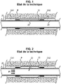
- the general structure of a known system of this type has been schematized Figures 1 and 2 attached.
- a known technique consists in positioning a deformable ductile membrane 10 of cylindrical geometry, around a casing 20, at the desired location.
- the membrane 10 is attached and sealed at its ends to the surface of the casing 20.
- a ring-shaped liner is defined between the outer surface of the casing 20 and the inner surface of the membrane 20.
- the inside of the casing 20 and the internal volume of the jacket formed by the membrane 20 communicate with each other by a passage 22 which passes through the wall of the casing 20.
- the membrane 10 is then expanded radially outwards until it is in contact with the wall P of the well, as seen in FIG. figure 2 , by increasing the pressure P1 in the casing 20.
- the membrane 10 seals on this wall P and the two annular spaces EA1 and EA2 defined between the wall P of the formation and the wall of the casing 20 are then isolated.
- the membrane 10 may be metal or elastomer, reinforced or not with fibers.
- the membrane 10 is made of elastomer and the circulation of the inflation fluid is without valve in the passage 22, the membrane resumes a shape close to its initial state, if the pressure is released inside the casing, after the have swollen. The membrane 10 then no longer serves as isolation of the annular space.
- the membrane 10 is metallic and the circulation of the inflation fluid between the inside of the membrane 10 and the inside of the casing 20 takes place directly, once permanently deformed, the membrane 10 retains in principle its shape and its shape. Barrier function in the annular space is also maintained when the pressure in the casing 20 is relaxed. However, if the pressure increases in the annular space, for example, on the EA1 side, the pressure differential between EA1 and the inside of the membrane 10 may be sufficient to collapse the metal membrane 10. It then no longer holds role of isolation of the annular space.
- the orifice 22 allowing the circulation of the inflation fluid between the inside of the casing 20 and the inside of the membrane 10 may be provided with a valve check.
- This valve traps the volume of inflation under pressure inside the membrane 10 at the end of inflation. Nevertheless, if the temperature and / or the pressure in the annular space change, the volume inside the membrane can also change. If the pressure decreases, the membrane 10 can collapse or lose its tight contact with the wall P of the well. The insulation function of the annular space is then no longer ensured. If on the contrary the pressure increases, the membrane 10 can deform to breaking. If the membrane 10 does not break, there is a risk that the pressure increases sufficiently inside the membrane 10 to collapse the wall of the casing 20.
- a second orifice provided between the membrane 10 and the high pressure zone EA1 which integrates a rupture disk.
- the latter makes it possible to create an opening between the inside of the membrane 10 and the zone EA1 at high pressure at the end of the inflation. In this way, evolutions of the well temperature or of the pressure on the EA1 side have no more effect on the pressure inside the membrane 10 since the membrane 10 is in communication with the annular space.
- the anti-return valve provided in the passage 22 passes the casing fluid 20 to the membrane 10 and the membrane 10 directly into the annular space.
- the document WO 2010/136806 also provides in replacement of the aforementioned rupture disc, a second orifice between the membrane 10 and the casing 20 with a valve-type valve that allows to evacuate the overpressure of the metal membrane 10.
- This solution is suitable when the volume and pressure increase to However, if the volume trapped in the membrane 10 decreases, the risk of collapsing the membrane 10 or losing contact between the membrane 10 and the wall P of the well persists.
- the object of the invention is to provide a device that solves the aforementioned problems.
- an isolation device for the treatment of a well comprising an expandable sleeve placed on a casing and an assembly adapted to control the supply of the internal volume of the jacket using a fluid under pressure from the casing, through a passage passing through the wall of the casing, to expand the liner radially outwards
- said assembly comprises a non-return valve placed in a passage which connects the volume internal casing to the internal volume of the jacket and means forming a three-way valve adapted to be switched once between an initial state in which a connection is established between the internal volume of the casing and the internal volume of the jacket to expand said liner and an end state in which the connection between the internal volume of the casing and the internal volume of the liner is interrupted and a connection is established between the volu internal of the liner and an annular volume of the outer well to the liner and casing, the said three-way valve and the said check valve forming, after switching, two valves mounted in series and in opposite directions on
- the means forming a three-way valve define a temporary intermediate state which intervenes between the initial state and the final state and in which the connection between the internal volume of the casing and the internal volume of the jacket is interrupted, but the connection between the internal volume of the jacket and the annular volume of the well outside the jacket and the casing is not yet established.
- the non-return valve placed in the passage which connects the internal volume of the casing to the internal volume of the liner is a valve biased resiliently to the closure, which opens under a pressure of fluid which exerts in the direction from the internal volume of the casing to the internal volume of the jacket.
- the non-return valve placed in the passage which connects the internal volume of the casing to the internal volume of the liner is a valve biased elastically to the closure, which opens under a fluid pressure which exerts in the direction from the internal volume of the liner to the internal volume of the casing, said valve being initially held in the open position by a temporary means, for example a retaining element capable of rupture and / or degradation.
- the valves are check valves in which a metal shutter rests on a metal seat preferably conical.
- the nonreturn valve placed in the passage which connects the internal volume of the casing to the internal volume of the jacket and the three-way valve are formed of two distinct subassemblies, for example placed in separate parallel longitudinal channels formed in the body of the assembly.
- the means which control the closing of the communication between the internal volume of the casing and the internal volume of the liner comprise a retaining element capable of breaking or a damaging retaining element or a combination of a first retaining element which must break with a second retaining element which must degrade.
- the three-way valve comprises a body which defines a chamber in which communication ducts open respectively with the inside of the casing, the inside of the expandable casing and the annular space situated outside the casing.
- casing a piston mounted in translation in said chamber and releasable means of immobilization, frangible and / or degradable, which initially immobilize the piston in an initial position such that the piston only allows communication between the associated pipes inside the casing and inside the expandable sleeve, then release the piston so that the piston occupies a end position in which it allows a communication between the associated conduits inside the expandable sleeve and the annular space outside the casing while prohibiting any further switching to the initial position when the piston has reached the position final.
- the piston and the releasable immobilization means define a temporary intermediate position between the initial position and the final position, in which the three communication ducts associated respectively with the inside of the casing, the The interior of the expandable sleeve and the annular space outside the casing are insulated from each other.
- the invention also relates as such to the aforementioned assemblies comprising in combination a non-return valve and a three-way valve forming, after switching, two valves mounted in series and in opposite directions.
- the invention furthermore relates to a method of isolating two annular zones of a well, implementing a step of feeding an expandable sleeve placed on a casing using a fluid under pressure coming from the casing.
- for expanding the liner radially outwards characterized in that it comprises the steps of supplying the internal volume of the expansible liner via a non-return valve placed in a passage which connects the volume internal casing to the internal volume of the jacket and then operate the switching of a three-way valve between an initial state in which a connection is established between the internal volume of the casing and the internal volume of the jacket to expand said jacket and an end state in wherein the connection between the internal volume of the casing and the internal volume of the liner is interrupted and a connection is established between the internal volume of the liner and an annular volume of the well outside the jacket and the casing, the said three-way valve and said non-return valve forming, after switching, two valves mounted in series and in opposite directions on the passage connecting the internal volumes of
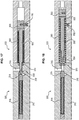
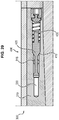
- an isolation device comprising an expandable sleeve 100 placed on a casing 200, facing a passage 222 passing through the wall of the casing 200 and a set 300 adapted to control the expansion of the jacket 100.
- the assembly 300 comprises an inlet nonreturn valve 400 and a three-way valve 500 adapted to be switched once and formed, after switching, in combination with the inlet valve 400, two non-return valves mounted in series and opposite directions on a passage connecting the internal volume 202 of the casing 200 and the internal volume 102 of the liner 100.
- the jacket 100 is advantageously formed of a cylindrical metal shell of revolution engaged on the outside of the casing 200 and whose two axial ends 110, 112 are sealingly connected to the outer surface of the casing 200 at these two axial ends. 110 and 112.
- the assembly 300 is adapted to initially supply the internal volume 102 of the jacket. 100 using a fluid under pressure from the casing 200, through the passage 222 through the wall of the casing 200, to expand the jacket 100 radially outwardly as seen on the figure 4 .
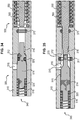
- said assembly 300 comprises a non-return valve 400 placed in the passage 222 which connects the internal volume 202 of the casing 200 to the internal volume 102 of the liner 100 and means 500 forming a three-way valve adapted to be switched once between an initial state corresponding to the figure 4 , in which a connection is established between the internal volume 202 of the casing 200 and the internal volume 102 of the jacket 100 to expand said jacket 100 and a final state corresponding to the figure 5 in which the connection between the internal volume 202 of the casing 200 and the internal volume 102 of the jacket 100 is interrupted, while a connection is established between the internal volume 102 of the jacket 100 and an annular volume EA1 of the outer well P to the liner 100 and the casing 200, to prevent the membrane component of the liner 100 from collapsing, in particular under the pressure of the annular volume EA1.
- the internal volume 102 of the jacket 100 is thus subjected to the same pressure as the annular volume EA1, the jacket 100 is not dependent on
- the valve 500 defines a temporary intermediate state between the initial state and the final state, in which no connection is established between the internal volume 202 of the casing 200, the internal volume 102 of the jacket 100 and the annular volume EA1.
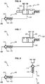
- a set 300 according to a first variant embodiment of the present invention comprising in combination a three-way two-way valve 500 and a non-return valve 400 at the inlet.
- the non-return valve 400 is placed in a duct coming from the internal volume 202 of the casing 200 and leading to a first channel 502 of the valve 500. It comprises a body which defines a tapered seat 410 flared away from the inlet coming from the internal volume 202 of the casing 200, a shutter 420 placed downstream of the seat 410 relative to a fluid supply direction ranging from the internal volume 202 of the casing 200 to the internal volume 102 of the liner 100 and a spring 430 which urges the shutter 420 to bear tightly against the seat 410 and thereby urging the valve 400 to the closure.
- the seat 410 and the shutter 420 are advantageously made of metal defining a valve 400 metal / metal.
- valve 400 At rest the valve 400 is closed under the bias of the spring 430.
- the pressure exerted downstream by a fluid applied from the internal volume 202 of the casing 200 exceeds the setting force exerted by the spring 430 this pressure pushes the shutter 420 and opens the valve 400.
- any pressure exerted from the downstream upstream that is to say from the internal volume 102 of the jacket 100, tends to reinforce the solicitation of the shutter 420 against its seat and therefore the valve 300 closing.
- the two other channels 504 and 506 of the valve 500 are respectively connected with the internal volume 102 of the jacket 100 and with the annular volume EA1 of the P-well.
- the valve 500 provides a link between the channels 502 and 504 and therefore between the outlet of the valve 400, the internal volume 202 of the casing 200, when the valve 400 is open, and the internal volume 102 of the jacket 100.
- the valve 500 provides a link between the channels 504 and 506.
- the connection between the output of the valve 400 and the internal volume 102 of the jacket 100 is interrupted and a connection is established between the internal volume 102 of the jacket 100 and the volume ring EA1 of the well.
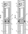
- the final state represented on the figure 7 is obtained after rupture or degradation of a pin 590 associated with the piston of the slide 500. It will be observed that the pressure applied from the nonreturn valve 400 remains in the internal volume 102 of the jacket 100 until rupture or degradation of the pawn 590.
- valve 500 comprises a piston adapted to define in the final switched state a second valve 510 in the opposite direction to the valve 400, on the passage leading from the internal volume 202 of the casing 200 to the internal volume 102 of the jacket 100.
- equivalent scheme of the assembly 300 thus obtained in the final switched state is represented on the figure 8 .
- valve 510 comprising a body which defines a tapered seat 512 flared near the inlet from the internal volume 202 of the casing 200, a shutter 514 placed upstream of the seat 512 with respect to a fluid supply direction ranging from the internal volume 202 of the casing 200 to the internal volume 102 of the liner 100 and a spring 516 which urges the shutter 514 in sealing engagement against the seat 512 and thereby causing the valve 510 to close.
- the seat 512 and the shutter 514 are advantageously made of metal defining a valve 500 metal / metal.
- valve 510 In the initial state of the valve 500, the valve 510 is open. When switching the valve 500 after rupture or degradation of the pin 590, the valve 510 closes under the bias of the spring 516.
- the assembly then comprises two valves 400 and 510 of opposite direction, back to back, which prohibit any circulation fluid in any direction between the internal volume 202 of the casing 200 and the internal volume 102 of the jacket 100.
- FIGS. Figures 9 to 11 We will now describe the structure and operation of the assembly 300 according to a second variant embodiment of the present invention, illustrated in FIGS. Figures 9 to 11 and also comprising in combination a three-way two-way valve 500 and a non-return valve 400 at the inlet.
- the non-return valve 400 is placed in the duct coming from the internal volume 202 of the casing 200 and leading to the first channel 502 of the valve 500. It comprises a body which defines a flared conical seat 410 in proximity to the inlet coming from the internal volume 202 of the casing 200, a shutter 420 placed upstream of the seat 410 with respect to a fluid supply direction from the internal volume 202 of the casing 200 to the internal volume 102 of the jacket 100 and a spring 430 which solicits the shutter 420 sealingly bears against the seat 410 and doing so which solicits the valve 400 closing.
- the seat 410 and the shutter 420 are preferably metal defining a valve 400 metal / metal.
- the shutter 420 In the initial state the shutter 420 is, however, kept away from the seat 410 by a pin 490 capable of breaking or degradation as shown in FIG. figure 9 .
- the valve 400 is then open. The valve 400 switches to the closed state during the rupture or degradation of the pin 490 under the bias of the spring 430.
- the two other channels 504 and 506 of the valve 500 are respectively connected with the internal volume 102 of the jacket 100 and with the annular volume EA1 of the well P and in the initial state represented on the figure 9 the valve 500 provides a link between the channels 502 and 504 and therefore between the outlet of the valve 400, the internal volume 202 of the casing 200, as the valve 400 is open, and the internal volume 102 of the jacket 100.
- the valve 500 provides a link between the channels 504 and 506.
- the connection between the output of the valve 400 and the internal volume 102 of the jacket 100 is interrupted and a connection is established between the internal volume 102 of the jacket 100 and the volume ring EA1 of the well.
- the final state represented on the figure 10 is also obtained after rupture or degradation of a pin 590 associated with the piston of the drawer 500.
- FIG. figure 11 schematically the valve 510 formed by the piston of the valve 500, comprising a body which defines a conical seat 512 flared away from the inlet from the internal volume 202 of the casing 200, a shutter 514 placed downstream of the seat 512 by relative to a direction of supply of fluid from the internal volume 202 of the casing 200 to the internal volume 102 of the jacket 100 and a spring 516 which urges the shutter 514 in sealing engagement against the seat 512 and in doing so which solicits the valve 510 at closing.
- the valve 510 formed by the piston of the valve 500 comprising a body which defines a conical seat 512 flared away from the inlet from the internal volume 202 of the casing 200, a shutter 514 placed downstream of the seat 512 by relative to a direction of supply of fluid from the internal volume 202 of the casing 200 to the internal volume 102 of the jacket 100 and a spring 516 which urges the shutter 514 in sealing engagement against the seat 512 and in doing so which solicits the valve 510 at closing
- valve 510 In the initial state of the valve 500, the valve 510 is open. When switching the valve 500 after rupture or degradation of the pin 590, the valve 510 closes under the bias of the spring 516.
- the assembly then comprises two valves 400 and 510 opposite direction, facing each other, which prohibit any circulation fluid in any direction between the internal volume 202 of the casing 200 and the internal volume 102 of the jacket 100.
- the three-way valve 500 can be the subject of many embodiments. It preferably comprises a piston 550 equipped with one and / or associated with a metal shutter 514 mounted in translation in a metal body 310 of the assembly. More precisely, the piston 550 is mounted in translation in a chamber 320 of this body 310 in which ducts corresponding to the channels 502, 504 and 506 open and are respectively connected to the internal volume 202 of the casing 200, to the internal volume 102 of the jacket 100 and internal volume EA1 of the well P.
- body 310 comprising the assembly of the housing housing the functional elements of the three-way valve 500 and, if applicable, of the inlet valve 400 , and can be composed of several pieces.
- the chamber 320 and the piston 550 are staggered and the conduits 502, 504 and 506 open at locations distributed longitudinally in the internal chamber 320, so that depending on the axial position of the piston 550 in the chamber 320, two of the conduits 502 and 504 or 504 and 506 are successively connected.
- the inlet valve 400 and the valve 500 are preferably formed in longitudinal parallel distinct channels formed in the body 310 of the assembly 300 parallel to the longitudinal axis of the casing 200. the aforementioned longitudinal channels being connected by transverse passages.
- upstream and downstream will be used with reference to the direction of movement of a fluid from the internal volume 202 of the casing 200 to the internal volume 102 of the jacket 100.
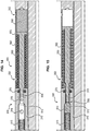
- the assembly 300 comprises in the body 310, two longitudinal channels 330 and 340 parallel to each other and parallel to the axis O-O of the casing 200.
- the channels 330 and 340 are located in different radial planes.
- the channel 330 houses the inlet valve 400.
- the channel 340 houses the three-way valve 500.
- the longitudinal channel 330 communicates with the internal volume 202 of the casing 200, on a first axial end, by a radial channel 312 closed at its radially outer end by a plug 314.
- the longitudinal channel 330 communicates with the second longitudinal channel 340 via a transverse passage 316.
- the longitudinal channel 340 has a second transverse passage 318 which communicates with the internal volume 102 of the liner and an orifice 350 which opens radially outwards in the annular volume EA1 of the well.
- the passage 316, the passage 318 and the orifice 350 form the three channels 502, 504 and 506 of the valve 500.
- a parachute valve 360 mounted on the radially inner inlet end of the radial channel 312.
- the valve 360 comprises a mushroom-shaped shutter 362 whose flared head is directed towards the internal volume 202 of the casing 200.
- the shutter 362 is biased at the opening by a spring bearing on the plug 314 to maintain the valve 360 at the opening, at rest, and thus allow the supply of the internal volume 102 of the expandable sleeve 100.
- valve 360 The role of the valve 360 is to close the channel 312 if the fluid flow exceeds a threshold, for example in case of rupture of the expandable sleeve 100. This closure of the valve 360 occurs when the pressure drop at the inlet of the latter creates on the flared head of the shutter 362 a force greater than the setting of the associated spring.
- an inlet parachute valve 360 can equip all the embodiments according to the invention.
- the first longitudinal channel 330 has a conical zone 410 diverging away from the first end connected to the radial inlet channel 312 and which forms the aforementioned seat of the valve 400.
- This conical zone 410 is located upstream of the channel 316.
- the channel 330 houses, facing this seat 410, a shutter 420 having a complementary conical end biased against the seat 410 by a spring 430.
- such a valve 400 is closed at rest and opens when the valve 500 being passing between the internal volume 202 of the casing 200 and the internal volume 102 of the jacket 100, the pressure exerted on the shutter 420 by the fluid present in the casing 200 exceeds the force of the spring 430.
- the second longitudinal channel 340 has a conical zone 512 located axially between the two ducts 316 and 318.
- the zone 512 is divergent towards the first duct 316 and forms the aforementioned seat of the valve 510.
- the channel 340 houses a piston 550 and a shutter 514 capable of translation.
- the shutter 514 is placed upstream of the piston 550 and rests on the upstream end 556 of the piston 550. It has opposite the seat 512, a conical area complementary to the seat 512. The shutter 514 is biased against the seat 512 by a spring 516.
- the conical shutter 514 is kept away from the seat 512 by the piston 550 and a degradable pin 590 placed in the bottom of the channel 340 opposite a piston tail 552 axially extending the piston 550 downstream shutter 514.
- the channel 340 also houses an O-ring 370 or any other equivalent means (O-ring associated with a ring for example) in contact with an intermediate portion 554 of the piston 550.
- the seal 370 is placed axially between the conduit 318 and the orifice 350, which leads 318 and port 350 are both located downstream of the seat 512.
- the seal 370 seals with the outer surface of the piston 550 in the initial position of the three-way valve 500 and up to the displacement of the shutter 514 against the seat 512.
- the seal 370 thus makes it possible to isolate the downstream orifice 350, in initial position illustrated on the figures 13 and 14 in which communication is allowed between the internal volume 202 of the casing 200 and the internal volume 102 of the jacket 100 via the conduits 316 and 318 and in the intermediate position illustrated on the figure 15 in which the communication between the volume internal 202 of the casing 200 and the internal volume 102 of the liner 100 is interrupted by the contact of the shutter 514 against the seat 512.
- This spring 560 is interposed between a recess formed in the channel 340 and a flared head 553 formed on the downstream end of the piston rod 552.
- the body 310 preferably has a radial orifice 352 opening at the chamber which houses the degradable pin 590 and receives the flared head 553 to allow the evacuation of the material constituting the pin 590 and a free movement of the head 553.
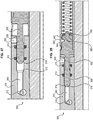
- the piston 550 After degradation of the pin 590, the piston 550 is moved in translation in the channel 340 under the effect of the spring 560. The portion 554 of the piston 550 then escapes the seal 370 and a communication is allowed between the conduit 318 linked to the internal volume 102 of the jacket 100 and the orifice 350 which opens into the annular volume EA1 of the well. In the position thus illustrated on the figure 16 , the valve 500 has reached its final irreversible switched position, the shutter 514 remaining in abutment against its seat 512 to isolate the conduit 316 of the conduit 318.
- FIG. 17 and 18 a second embodiment of a valve 500 according to the present invention intended to form in the switched state, in combination with the inlet valve 400, two opposing back-to-back valves, which is essentially different from the first embodiment illustrated on the Figures 12 to 16 in that the degradable pin 590 mentioned above is replaced by a breaking pin 592.
- This breaking pin 592 is carried by the body 310. It is oriented radially relative to the direction of translation of the piston 550 in the longitudinal channel 340 and initially interferes with the piston 550 or a stop 593 on which the piston 550 rests as one see him on the figure 17 to prohibit a displacement of the piston 550 and therefore a bringing the shutter 514 against the seat 512.
- the conduits 316 and 318 are then in communication.
- the pin 592 releases the piston 550 so that in an intermediate state the shutter 514 abuts against the seat 512, the conduits 316 and 318 and the orifice 350 are then isolated, then in the final switched state illustrated on the figure 18 , the piston 550 completes its stroke under the effect of the spring 560 so that a connection is established between the conduit 318 and the orifice 350.
- FIG. 19 a third embodiment of a valve according to the present invention intended to form, in the switched state, in combination with the inlet valve 400, two opposing back-to-back valves, which is essentially different from the first exemplary embodiment illustrated on the Figures 12 to 16 and the second embodiment illustrated on the Figures 17 and 18 in that the piston 550 is initially maintained by the combination of a degradable pin 590 and a breaker pin 592.
- the degradable peion 590 is interposed between the tail 552 of the piston 550 and a stop 593 associated with the breaking pin 592.
- the rupture pin 592 initially prohibits a displacement of the piston 550 and consequently a bringing of the shutter 514 against the seat 512.
- the conduits 316 and 318 are then in communication as shown in FIG. figure 19 .
- the pin 592 releases the piston 550 so that in an intermediate state the shutter 514 abuts against the seat 512, the conduits 316 and 318 and the orifice 350 are then isolated, then in the final switched state illustrated on the figure 20 , the 550 piston completes its course under the effect of the spring 560 so that a connection is established between the conduit 318 and the orifice 350, the portion 554 of the piston 550 escaping the seal 370.
- the degradable peion 590 eventually degrades after a certain time, after inflation of the liner 100, as shown in FIG. figure 21 , to also allow switching in the final state of the valve 500 in which the conduit 318 and the port 350 communicate with each other, but the inlet conduit 316 remains closed by the valve 510.
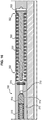
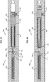
- the assembly 300 comprises in the body 310, four longitudinal channels 332, 330, 340 and 442 parallel to each other and parallel to the axis OO of the casing 200, respectively visible on the Figures 22, 23 , 24 and 26 .
- Channels 332, 330, 340 and 442 are located in different radial planes.
- the longitudinal channel 332 visible on the figure 22 is an inlet channel which communicates with the internal volume 202 of the casing 200, on a first axial end, by a radial channel 312 closed at its radially outer end by a plug 314 and equipped with a parachute valve 360.
- the channel 332 communicates via a transverse channel 317 with the longitudinal channel 330.
- the longitudinal channel 330 visible on the figure 23 receives the non-return valve 400.
- This longitudinal channel 330 communicates with the third longitudinal channel 340 visible on the Figures 24 and 25 by a passage transversal 316.
- the longitudinal channel 340 houses the three-way valve 500.
- the transverse input channel 316 opens onto a blind axial end of the longitudinal channel 340.
- the longitudinal channel 340 has a second transverse passage 318 which communicates with the fourth longitudinal channel 342 visible on the figure 26 , which opens into the internal volume 102 of the jacket 100, and an orifice 350 which opens radially outwardly in the annular volume EA1 of the well.
- the passage 316, the passage 318 and the orifice 350 form the three channels 502, 504 and 506 of the valve 500.
- the longitudinal channel 330 has a divergent conical zone 410 approaching the inlet channel 332 and which forms the aforementioned seat of the valve 400.
- This conical zone 410 is located downstream of the channel 317 and upstream of the channel 316.
- the channel 330 houses, facing this seat 410, a shutter 420 formed on the piston 450 and having a complementary conical end biased against the seat 410 by a spring 430.
- valve 400 is kept open initially by a degradable or breakable pin 490 and closes when the pin 490 is broken or degraded.
- the pin 490 is a degradable pin placed opposite the downstream end of the piston 450, beyond the conduit 316, in the bottom of the longitudinal channel 330.
- the longitudinal channel 340 has a conical zone 512 located axially between the two ducts 316 and 318.
- the zone 512 is divergent away from the first conduit 316 and form the aforementioned seat of the valve 510.
- the channel 340 houses a piston 550 capable of translation.
- the piston 550 has, facing the seat 512, a conical zone 514 complementary to the seat 512, forming a shutter.
- the piston 550, more particularly the shutter 514, is biased against the seat 512 by a spring 516.
- the conical shutter 514 is kept away from the seat 512 by a degradable pin, a breaking pin or the combination of a degradable pin and a breaking pin.
- the channel 340 also houses two O-rings 370 and 372 or any other equivalent means (O-ring associated with a ring for example) in contact with a portion 554 of the piston 550 adjacent to the conical shutter 514.
- the gasket 370 is placed axially between the duct 318 and the orifice 350, which ducts 318 and orifice 350 are both located downstream of the seat 512. As can be seen in FIGS. Figures 24 and 25 , the seal 370 seals with the outer surface of the piston 550 in the initial position of the three-way valve 500 and up to the displacement of the shutter 514 against the seat 512.
- the seal 370 thus makes it possible to isolate the orifice downstream 350, in initial position illustrated on the Figures 24 and 25 in which communication is allowed between the internal volume 202 of the casing 200 and the internal volume 102 of the liner 100 via the ducts 316 and 318 and in transient intermediate position illustrated on the figure 27 in which the communication between the internal volume 202 of the casing 200 and the internal volume 102 of the liner 100 is interrupted by the piston 550.
- the seal 372 is placed axially between the duct 316 and the duct 318, downstream of the seat 512, the ducts 316 and 318 being located respectively on either side of the seat 512.
- the seal 372 makes it possible to seal on the piston 550 and thus to isolate the two conduits 316 and 318 in the event of leakage of the valve 510, in particular in the transient phase of displacement of the piston towards its final switched position as shown in FIG. figure 27 .
- the figure 29 represents the inlet valve 400 in the closed switched position, the shutter 420 resting against the seat 410 after degradation of the pin 490.
- the piston 550 of the valve 500 is associated with a non-return mechanism 580 which prevents a rearward displacement of the piston such that the piston 550 would escape the seal 372, once the switching initiated.
- a mechanism 580 can be the subject of many embodiments. According to the particular and nonlimiting embodiment illustrated on the Figures 24, 25 , 28 and 30 this mechanism 580 is formed of a piece 582 interposed between the piston 550 and the spring 516, which has two bearing faces 584 and 586 respectively directed towards the piston 550 and the spring 516, not parallel to each other.
- the cross section of the piece 582 is smaller than the cross section of the local zone of the channel 340 to allow the engagement and the sliding of this part 582.
- the part 582 is however obliquely displaced in the channel 340 and is then along a diagonal of greater length opposite a recess 348 formed in the channel 340.
- the cooperation of the part 582 and the recess 348 illustrated on the figure 30 prohibits the return of piston 550 to its original position.
- Such a mechanism 580 is however optional and not mandatory.
- the valve 500 is constituted such that the reverse movement of the piston 550 is impossible even if a differential pressure, positive or negative, exists between the annular space EA1 and the inside of the casing 200.
- the invention solves the problems posed according to the state of the art.
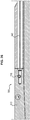
- annular pressure varies over time and can alternatively be: pressure of EA1> pressure of EA2 or pressure of EA2> pressure of EA1, it is conceivable to mount two zone isolation devices according to the invention head to tail as illustrated on the figure 31 .
- Valves 400 and 510 have previously been described whose seat 410, 512 and the shutter 420, 514 are advantageously made of metal thus defining valves 400, 510 metal / metal.
- valve 400 and / or 510 is and remains sealed even if the shutter 420 or 514 would not rest perfectly against its associated seat 410 or 512, for example in the case where the fluid carried is not properly filtered.
- Such an additional seal may be provided on the shutter and be adapted to bear against a complementary bearing formed on the body housing the valve and forming the seat, when the valve is in its closed position or close to its closed position.
- the seal may alternatively be provided on the body housing the valve and forming the seat, and then be adapted to bear against a complementary bearing formed on the shutter, when the valve is in its closed position or close to its position closure.
- FIG. 32 to 34 illustrate an alternative of the embodiment shown on the Figures 13 to 16 , an embodiment in which an additional seal 570 is mounted in a groove formed on the shutter 514.
- This seal 570 is adapted to bear against a complementary bearing 511 formed at a recess on the body 310 housing the valve 510, in the extension and upstream of the seat 512.
- the diameter of the section of the chamber 320 which receives the shutter 514 and which houses the seal 370 in the initial position as illustrated on the figure 32 is preferably greater than the diameter of the seal 370.
- the diameter of the recess which forms the bearing surface 511 is however at least slightly less than the outer diameter at rest of the seal 570 to ensure the aforementioned seal.
- the travel of the shutter 514 is such that in the initial position as illustrated on FIG. figure 32 , the seal 570 is placed beyond the inlet duct 316 so as not to disturb the flow of fluid ensuring the inflation of the liner 100.
- the duct 316 is located, in the initial position, between the gasket 570 and the scope 511.
- the figure 33 shows the valve 510 in the closed position similar to the figure 16 , the shutter 514 resting against the seat 512.
- the figure 34 shows the seal provided by the seal 570 resting against the bearing 511 in the case where the shutter 514 is slightly detached from the complementary conical seat 512.
- valve 510 As indicated above the provision of an additional seal ensuring the tightness of the valve in the event of separation of the shutter, can be applied to all embodiments of the valve 510 as well as to all the embodiments. of the valve 400, and this is in seal-mounted version mounted on the shutter cooperating with a complementary seat-side seat-mounted seat-mounted seal and cooperating with a complementary bearing surface formed on the shutter.
- valve 510 in which the seal 570 is placed in a groove 311 formed in the body 310 incorporating the seat 512 to cooperate with a complementary surface 515 formed on the shutter 514.
- valve 400 in the closed position, an alternative embodiment of a valve 400 according to which a seal 470 is placed in a groove 422 formed in the body of the shutter 420 to cooperate with a complementary surface 412 formed on the body 310 incorporating the seat 410.
- FIG. 37 in the closed position, another alternative embodiment of a valve 400 according to which a seal 470 is placed in a groove 313 formed in the body 310 incorporating the seat 410 to cooperate with a complementary surface 424 formed on the shutter 420.
Landscapes
- Life Sciences & Earth Sciences (AREA)
- Engineering & Computer Science (AREA)
- Geology (AREA)
- Mining & Mineral Resources (AREA)
- Physics & Mathematics (AREA)
- Environmental & Geological Engineering (AREA)
- Fluid Mechanics (AREA)
- General Life Sciences & Earth Sciences (AREA)
- Geochemistry & Mineralogy (AREA)
- Details Of Valves (AREA)
- Safety Valves (AREA)
- Check Valves (AREA)
Claims (16)
- Vorrichtung zur Isolierung für die Behandlung eines Schachts, umfassend eine expandierbare Umhüllung (100), die auf einer Küvelage (200) angeordnet ist, und eine Einheit (300), die ausgelegt ist, um die Versorgung des inneren Volumens (102) der Umhüllung (100) mit Hilfe eines Fluids unter Druck, das aus der Küvelage (200) stammt, durch einen Durchgang (222), der die Wand der Küvelage (200) quert, zu steuern, um die Umhüllung (100) radial nach außen zu expandieren, wobei die Einheit (300) ein Rückschlagventil (400) umfasst, das in einem Durchgang angeordnet ist, der das innere Volumen (202) der Küvelage (200) mit dem inneren Volumen (102) der Umhüllung (100) verbindet, und Mittel (500), die einen Dreiwegschieber bilden, der ausgelegt ist, um ein einziges Mal zwischen einem anfänglichen Zustand, in dem eine Verbindung zwischen dem inneren Volumen (202) der Küvelage (200) und dem inneren Volumen (102) der Umhüllung (100) aufgebaut ist, um die Umhüllung (100) zu expandieren, und einem endgültigen Zustand geschaltet zu sein, in dem die Verbindung zwischen dem inneren Volumen (202) der Küvelage (200) und dem inneren Volumen (102) der Umhüllung (100) unterbrochen ist und eine Verbindung zwischen dem inneren Volumen (102) der Umhüllung (100) und einem ringförmigen Volumen (EA1) des äußeren Schachts an die Umhüllung (100) und an die Küvelage (200) aufgebaut ist, wobei der Dreiwegeschieber (500) und das Rückschlagventil (400) nach der Kommutation zwei Rückschlagventile (400, 510) bilden, die in Reihe und in entgegen gesetzten Richtungen auf dem Durchgang montiert sind, der die inneren Volumina der Küvelage (200) und der Umhüllung (100) verbindet.
- Vorrichtung nach Anspruch 1, dadurch gekennzeichnet, dass die Mittel (500), die einen Dreiwegschieber bilden, einen vorübergehenden Zwischenzustand definieren, der zwischen dem anfänglichen Zustand und dem endgültigen Zustand eintritt, und in dem die Verbindung zwischen dem inneren Volumen (202) der Küvelage (200) und dem inneren Volumen (102) der Umhüllung (100) unterbrochen ist, jedoch die Verbindung zwischen dem inneren Volumen (102) der Umhüllung (100) und dem ringförmigen Volumen (EA1) des äußeren Schachts an die Umhüllung (100) und an die Küvelage (200) noch nicht aufgebaut ist.
- Vorrichtung nach einem der Ansprüche 1 oder 2, dadurch gekennzeichnet, dass das Rückschlagventil (400), das im Durchgang angeordnet ist, der das innere Volumen (202) der Küvelage (200) mit dem inneren Volumen (102) der Umhüllung (100) verbindet, ein Ventil ist, das elastisch an den Verschluss vorgespannt ist, der sich unter einem Fluiddruck öffnet, der in der Richtung, die vom inneren Volumen (202) der Küvelage (200) zum inneren Volumen (102) der Umhüllung (100) verläuft, ausgeübt wird.
- Vorrichtung nach einem der Ansprüche 1 oder 2, dadurch gekennzeichnet, dass das Rückschlagventil (400), das im Durchgang angeordnet ist, der das innere Volumen (202) der Küvelage (200) mit dem inneren Volumen (102) der Umhüllung (100) verbindet, ein Ventil ist, das elastisch an den Verschluss vorgespannt ist, der sich unter einem Fluiddruck öffnet, der in der Richtung, die vom inneren Volumen (102) der Umhüllung (100) zum inneren Volumen (202) der Küvelage (200) verläuft, ausgeübt wird, wobei das Ventil (400) anfänglich durch ein vorübergehendes Mittel (490) in der offenen Position gehalten wird, z. B. ein Rückhalteelement, das gebrochen und/oder abgebaut werden kann.
- Vorrichtung nach einem der Ansprüche 1 bis 4, dadurch gekennzeichnet, dass die Ventile (400, 510) Rückschlagventile sind, in denen ein metallischer Verschluss (420, 514) auf einem metallischen Sitz (410, 512) liegt.
- Vorrichtung nach einem der Ansprüche 1 bis 5, dadurch gekennzeichnet, dass die Ventile (400, 510) Rückschlagventile mit einem konischen Sitz (410, 512) sind.
- Vorrichtung nach einem der Ansprüche 1 bis 6, dadurch gekennzeichnet, dass die Ventile (400, 510) ein Gelenk (470, 570) umfassen, das ausgelegt ist, um auf einem zusätzlichen Bereich (412, 424, 511, 515) zu liegen, wenn sich das Ventil (400, 510) in seiner Verschlussposition oder nahe seiner Verschlussposition befindet.
- Vorrichtung nach Anspruch 7, dadurch gekennzeichnet, dass das Gelenk (470, 570) auf dem Verschluss (420, 514) vorgesehen und ausgelegt ist, um auf einem zusätzlichen Bereich (412, 511) zu lagern, der auf dem Körper gebildet ist, der das Ventil aufnimmt und den Sitz (410, 512) bildet oder auf dem Körper (310) vorgesehen ist, der das Ventil aufnimmt und den Sitz (410, 512) bildet und ausgelegt ist, um auf einem zusätzlichen Bereich (424, 515) zu lagern, der auf dem Verschluss (420, 514) gebildet ist.
- Vorrichtung nach einem der Ansprüche 1 bis 8, dadurch gekennzeichnet, dass das Rückschlagventil (400), das im Durchgang angeordnet ist, der das innere Volumen (202) der Küvelage (200) mit dem inneren Volumen (102) der Umhüllung (100) verbindet, und der Dreiwegschieber (500) aus zwei verschiedenen Untereinheiten gebildet sind.
- Vorrichtung nach einem der Ansprüche 1 bis 9, dadurch gekennzeichnet, dass das Rückschlagventil (400), das im Durchgang angeordnet ist, der das innere Volumen (202) der Küvelage (200) mit dem inneren Volumen (102) der Umhüllung (100) verbindet, und der Dreiwegschieber (500) in verschiedenen parallelen Längskanälen (330, 340) angeordnet sind, die im Körper (310) der Einheit gebildet sind.
- Vorrichtung nach einem der Ansprüche 1 bis 10, dadurch gekennzeichnet, dass die Mittel (590, 592), die den Verschluss der Kommunikation zwischen dem inneren Volumen (202) der Küvelage (200) und dem inneren Volumen (102) der Umhüllung (100) steuern, ein Rückhalteelement (592) umfassen, das gebrochen werden kann, oder ein Rückhalteelement (590), das abgebaut werden kann, oder eine Kombination eines ersten Rückhalteelements (592), das brechen muss, mit einem zweiten Rückhalteelement (590), das abgebaut werden muss.
- Vorrichtung nach einem der Ansprüche 1 bis 11, dadurch gekennzeichnet, dass der Dreiwegschieber (500) einen Körper (310) umfasst, der eine Kammer (320) definiert, in die Leitungen (316, 318, 350) zur Kommunikation mit dem Inneren (202) der Küvelage (200), dem Inneren (102) der expandierbaren Umhüllung (100) bzw. dem ringförmigen Raum (EA1), der sich an der Außenseite der Küvelage befindet, münden, einen Kolben (550) der in Translation in der Kammer (320) montiert ist, und freisetzbare, zerbrechliche und/oder abbaubare Mittel zur Immobilisierung (590, 592), die anfänglich den Kolben (550) in einer anfänglichen Position immobilisieren, so dass der Kolben (550) lediglich eine Kommunikation zwischen den Leitungen (316, 318) zulässt, die mit dem Inneren (202) der Küvelage (200) und dem Inneren (102) der expandierbaren Umhüllung (100) assoziiert sind, dann den Kolben (550) freigeben, so dass der Kolben eine endgültige Position einnimmt, in der er eine Kommunikation zwischen den Leitungen (318, 350) zulässt, die mit dem Inneren (102) der expandierbaren Umhüllung (100) und mit dem ringförmigen Raum (EA1) assoziiert sind, der sich an der Außenseite der Küvelage (200) befindet, wobei gleichzeitig jede neue Kommutation hin zur anfänglichen Position verhindert wird, wenn der Kolben (550) die endgültige Position erreicht hat.
- Vorrichtung nach Anspruch 12, dadurch gekennzeichnet, dass der Kolben (550) und die freisetzbaren Mittel zur Immobilisierung (590, 592) eine Zwischenposition zwischen der anfänglichen Position und der endgültigen Position definieren, in der die drei Kommunikationsleitungen (316, 318, 350), die jeweils mit dem Inneren (202) der Küvelage (200), dem Inneren (102) der expandierbaren Umhüllung (100) und dem ringförmigen Raum (EA1), der sich an der Außenseite der Küvelage (200) befindet, assoziiert sind, untereinander isoliert sind.
- Einheit (300), umfassend in Kombination ein Rückschlagventil (400) und einen Dreiwegschieber (500) gemäß einem der Ansprüche 1 bis 13, die, nach der Kommutation, zwei Ventile (400, 510) bilden, die in Reihe und in entgegen gesetzten Richtungen, Rücken an Rücken oder Seite an Seite, auf dem Durchgang montiert sind, der die inneren Volumina einer Küvelage (200) und einer Umhüllung (100) einer Vorrichtung zur Isolierung von Schächten verbinden.
- Einheit nach Anspruch 14, dadurch gekennzeichnet, dass die Ventile (400, 510) Rückschlagventile sind, in denen ein metallischer Verschluss (420, 514) auf einem konischen metallischen Sitz (410, 512) liegt.
- Verfahren zur Isolierung von zwei ringförmigen Zonen (EA1, E12) eines Schachts, wodurch ein Schritt zur Versorgung einer expandierbaren Umhüllung (100), die auf einer Küvelage (200) angeordnet ist, mit Hilfe eines Fluids unter Druck, der aus der Küvelage (200) stammt, durchgeführt wird, um die Umhüllung (100) radial nach außen zu expandieren, wobei das Verfahren die Schritte umfasst, die darin bestehen, das innere Volumen (102) der expandierbaren Umhüllung (100) mit Hilfe eines Rückschlagventils (400) zu versorgen, das in einem Durchgang angeordnet ist, der das innere Volumen (202) der Küvelage (200) mit dem inneren Volumen (102) der Umhüllung (100) verbindet, dann die Kommutation eines Dreiwegschiebers (500) zwischen einem anfänglichen Zustand, in dem eine Verbindung zwischen dem inneren Volumen (202) der Küvelage (200) und dem inneren Volumen (102) der Umhüllung (100) aufgebaut ist, um die Umhüllung (100) zu expandieren, und einem endgültigen Zustand aufgebaut wird, zu betätigen, in dem die Verbindung zwischen dem inneren Volumen (202) der Küvelage (200) und dem inneren Volumen (102) der Umhüllung (100) unterbrochen ist und eine Verbindung zwischen den inneren Volumen (102) der Umhüllung (100) und einem ringförmigen Volumen (EA1) des äußeren Schachts mit der Umhüllung (100) und mit der Küvelage (200) aufgebaut ist, wobei der Dreiwegschieber (500) und das Rückschlagventil (400) nach der Kommutation zwei Rückschlagventile (400, 510) bilden, die in Reihe und in entgegen gesetzten Richtungen auf dem Durchgang montiert sind, der die inneren Volumina der Küvelage (200) und der Umhüllung (100) verbindet.
Applications Claiming Priority (2)
| Application Number | Priority Date | Filing Date | Title |
|---|---|---|---|
| FR1450214A FR3016389B1 (fr) | 2014-01-10 | 2014-01-10 | Dispositif d'isolation pour puits |
| PCT/EP2015/050345 WO2015104381A1 (fr) | 2014-01-10 | 2015-01-09 | Dispositif d'isolation pour puits |
Publications (2)
| Publication Number | Publication Date |
|---|---|
| EP3092368A1 EP3092368A1 (de) | 2016-11-16 |
| EP3092368B1 true EP3092368B1 (de) | 2017-11-29 |
Family
ID=50639701
Family Applications (1)
| Application Number | Title | Priority Date | Filing Date |
|---|---|---|---|
| EP15700542.2A Active EP3092368B1 (de) | 2014-01-10 | 2015-01-09 | Isoliervorrichtung für ein bohrloch |
Country Status (5)
| Country | Link |
|---|---|
| US (1) | US10060222B2 (de) |
| EP (1) | EP3092368B1 (de) |
| FR (1) | FR3016389B1 (de) |
| NO (1) | NO3092368T3 (de) |
| WO (1) | WO2015104381A1 (de) |
Families Citing this family (6)
| Publication number | Priority date | Publication date | Assignee | Title |
|---|---|---|---|---|
| FR3038931B1 (fr) * | 2015-07-15 | 2017-08-25 | Saltel Ind | Dispositif de protection d'un pion degradable pour systeme d'isolation dans une barriere annulaire |
| FR3038932B1 (fr) * | 2015-07-15 | 2018-08-17 | Saltel Ind | Dispositif d'isolation pour puits avec un disque de rupture |
| US11091975B2 (en) | 2017-03-27 | 2021-08-17 | Schlumberger Technology Corporation | Expandable metal packer system and methodology with annulus pressure compensation |
| US11788365B2 (en) | 2019-01-23 | 2023-10-17 | Saltel Industries Sas | Expandable metal packer system with pressure control device |
| EP3994333B1 (de) * | 2019-07-02 | 2025-09-03 | Services Pétroliers Schlumberger | Vorrichtung zum expandieren und kollabieren mit dichtungsdruckausgleich |
| US10662734B1 (en) * | 2019-09-14 | 2020-05-26 | Vertice Oil Tools | Methods and systems for preventing hydrostatic head within a well |
Family Cites Families (13)
| Publication number | Priority date | Publication date | Assignee | Title |
|---|---|---|---|---|
| US2935615A (en) * | 1957-06-24 | 1960-05-03 | Jersey Prod Res Co | Well logging tool fluid displacer |
| FR2791732B1 (fr) | 1999-03-29 | 2001-08-10 | Cooperation Miniere Et Ind Soc | Dispositif d'obturation d'un puits de forage |
| DE10135159C1 (de) * | 2001-07-19 | 2002-10-31 | Schmidt & Co Gmbh Kranz | Bohrlochverschluss |
| US6907936B2 (en) | 2001-11-19 | 2005-06-21 | Packers Plus Energy Services Inc. | Method and apparatus for wellbore fluid treatment |
| US6854522B2 (en) * | 2002-09-23 | 2005-02-15 | Halliburton Energy Services, Inc. | Annular isolators for expandable tubulars in wellbores |
| GB0417328D0 (en) | 2004-08-04 | 2004-09-08 | Read Well Services Ltd | Apparatus and method |
| US7591321B2 (en) | 2005-04-25 | 2009-09-22 | Schlumberger Technology Corporation | Zonal isolation tools and methods of use |
| WO2007075855A2 (en) * | 2005-12-21 | 2007-07-05 | Bj Services Company | Concentric coiled tubing annular fracturing string |
| ES2464457T3 (es) | 2009-01-12 | 2014-06-02 | Welltec A/S | Barrera anular y sistema de barrera anular |
| GB0909086D0 (en) | 2009-05-27 | 2009-07-01 | Read Well Services Ltd | An active external casing packer (ecp) for frac operations in oil and gas wells |
| US20120227969A1 (en) * | 2009-11-19 | 2012-09-13 | Ian Gray | External Casing Packer |
| EP2565369A1 (de) * | 2011-08-31 | 2013-03-06 | Welltec A/S | Ringförmige Absperrung mit Ausgleichsvorrichtung |
| GB2511503B (en) * | 2013-03-04 | 2019-10-16 | Morphpackers Ltd | Expandable sleeve with pressure balancing and check valve |
-
2014
- 2014-01-10 FR FR1450214A patent/FR3016389B1/fr active Active
-
2015
- 2015-01-09 WO PCT/EP2015/050345 patent/WO2015104381A1/fr not_active Ceased
- 2015-01-09 US US15/110,536 patent/US10060222B2/en active Active
- 2015-01-09 NO NO15700542A patent/NO3092368T3/no unknown
- 2015-01-09 EP EP15700542.2A patent/EP3092368B1/de active Active
Also Published As
| Publication number | Publication date |
|---|---|
| FR3016389A1 (fr) | 2015-07-17 |
| FR3016389B1 (fr) | 2016-01-08 |
| NO3092368T3 (de) | 2018-04-28 |
| WO2015104381A1 (fr) | 2015-07-16 |
| US10060222B2 (en) | 2018-08-28 |
| US20160341003A1 (en) | 2016-11-24 |
| EP3092368A1 (de) | 2016-11-16 |
Similar Documents
| Publication | Publication Date | Title |
|---|---|---|
| EP3092368B1 (de) | Isoliervorrichtung für ein bohrloch | |
| CA2841797C (fr) | Dispositif d'isolation d'une partie d'un puits | |
| FR3003891A1 (fr) | Dispositif de commande et d'isolation d'un outil en forme de chemise expansible pour l'isolation de zones dans un puits | |
| EP0325541B1 (de) | Vorrichtung und Verfahren zum Isolieren produzierender Schichten in einer Bohrung | |
| WO2017009463A1 (fr) | Dispositif de protection d'un pion dégradable pour système d'isolation dans une barrière annulaire | |
| FR2712024A1 (fr) | Système de complétion à tube de production, flexible enroulable. | |
| EP3099967B1 (de) | Werkzeug zur bearbeitung der wand eines rohres und entsprechendes verfahren | |
| EP3167148A1 (de) | Aufweitbares röhrenförmiges element zur aufnahme von einer oder mehreren aufblasbaren dichtungen | |
| FR2716930A1 (fr) | Valve de commande annulaire, apte à être positionnée dans un tube de production flexible. | |
| WO2017009460A1 (fr) | Dispositif d'isolation pour puits avec un disque de rupture | |
| FR2970998A1 (fr) | Vanne de securite souterraine incluant une injection d'additif securisee | |
| FR2893973A1 (fr) | Procede et dispositif de cimentation d'un puits ou d'une canalisation | |
| FR2717532A1 (fr) | Elément de suspension de tube incorporant un joint. | |
| CA2311275C (fr) | Dispositif de securite universel et procede de protection d'une canalisation | |
| CA2885071A1 (fr) | Ancre de couple de blocage en rotation d'une colonne de production d'un puits, systeme de pompage et de blocage en rotation, et installation de pompage equipee d'une telle ancre de couple | |
| EP1360392B1 (de) | Sicherheitsventil für ölbohrlöcher | |
| EP3158164A1 (de) | Vorrichtung zum auskleiden oder verschliessen eines bohrloches oder einer rohrleitung | |
| FR2476204A1 (fr) | Systeme de suspension a brides pour suspendre des colonnes de tubage et de pompage dans des puits de petrole ou de gaz haute pression | |
| FR2989412A1 (fr) | Conduite pourvue d'un element metallique serti | |
| FR2666116A1 (fr) | Vanne de securite de l'espace annulaire et procede pour commander l'ecoulement de fluides entre des conduits tubulaires exterieur et interieur. | |
| EP3237723B1 (de) | Vorrichtung zum isolieren eines teils eines bohrlochs oder einer rohrleitung sowie in solch einer isolierungsvorrichtung implementierte steuerungseinrichtungen | |
| FR3038648A1 (fr) | Dispositif de cimentation d’une conduite dans un puits de forage et procede de cimentation correspondant | |
| FR2878586A1 (fr) | Ensemble d'entrainement a reservoir etanche | |
| FR2968377A1 (fr) | Dispositif d'obturation d'une conduite de transport de fluide, conduite et procede de controle | |
| FR3012512A1 (fr) | Chemise metallique expansible et dispositif qui en fait usage |
Legal Events
| Date | Code | Title | Description |
|---|---|---|---|
| PUAI | Public reference made under article 153(3) epc to a published international application that has entered the european phase |
Free format text: ORIGINAL CODE: 0009012 |
|
| 17P | Request for examination filed |
Effective date: 20160809 |
|
| AK | Designated contracting states |
Kind code of ref document: A1 Designated state(s): AL AT BE BG CH CY CZ DE DK EE ES FI FR GB GR HR HU IE IS IT LI LT LU LV MC MK MT NL NO PL PT RO RS SE SI SK SM TR |
|
| AX | Request for extension of the european patent |
Extension state: BA ME |
|
| DAX | Request for extension of the european patent (deleted) | ||
| GRAP | Despatch of communication of intention to grant a patent |
Free format text: ORIGINAL CODE: EPIDOSNIGR1 |
|
| INTG | Intention to grant announced |
Effective date: 20170717 |
|
| GRAS | Grant fee paid |
Free format text: ORIGINAL CODE: EPIDOSNIGR3 |
|
| GRAA | (expected) grant |
Free format text: ORIGINAL CODE: 0009210 |
|
| AK | Designated contracting states |
Kind code of ref document: B1 Designated state(s): AL AT BE BG CH CY CZ DE DK EE ES FI FR GB GR HR HU IE IS IT LI LT LU LV MC MK MT NL NO PL PT RO RS SE SI SK SM TR |
|
| REG | Reference to a national code |
Ref country code: CH Ref legal event code: EP |
|
| REG | Reference to a national code |
Ref country code: AT Ref legal event code: REF Ref document number: 950572 Country of ref document: AT Kind code of ref document: T Effective date: 20171215 |
|
| REG | Reference to a national code |
Ref country code: IE Ref legal event code: FG4D Free format text: LANGUAGE OF EP DOCUMENT: FRENCH |
|
| REG | Reference to a national code |
Ref country code: DE Ref legal event code: R096 Ref document number: 602015006340 Country of ref document: DE |
|
| REG | Reference to a national code |
Ref country code: FR Ref legal event code: PLFP Year of fee payment: 4 |
|
| REG | Reference to a national code |
Ref country code: NL Ref legal event code: MP Effective date: 20171129 |
|
| REG | Reference to a national code |
Ref country code: LT Ref legal event code: MG4D |
|
| REG | Reference to a national code |
Ref country code: AT Ref legal event code: MK05 Ref document number: 950572 Country of ref document: AT Kind code of ref document: T Effective date: 20171129 |
|
| PG25 | Lapsed in a contracting state [announced via postgrant information from national office to epo] |
Ref country code: FI Free format text: LAPSE BECAUSE OF FAILURE TO SUBMIT A TRANSLATION OF THE DESCRIPTION OR TO PAY THE FEE WITHIN THE PRESCRIBED TIME-LIMIT Effective date: 20171129 Ref country code: ES Free format text: LAPSE BECAUSE OF FAILURE TO SUBMIT A TRANSLATION OF THE DESCRIPTION OR TO PAY THE FEE WITHIN THE PRESCRIBED TIME-LIMIT Effective date: 20171129 Ref country code: SE Free format text: LAPSE BECAUSE OF FAILURE TO SUBMIT A TRANSLATION OF THE DESCRIPTION OR TO PAY THE FEE WITHIN THE PRESCRIBED TIME-LIMIT Effective date: 20171129 Ref country code: LT Free format text: LAPSE BECAUSE OF FAILURE TO SUBMIT A TRANSLATION OF THE DESCRIPTION OR TO PAY THE FEE WITHIN THE PRESCRIBED TIME-LIMIT Effective date: 20171129 |
|
| REG | Reference to a national code |
Ref country code: NO Ref legal event code: T2 Effective date: 20171129 |
|
| PG25 | Lapsed in a contracting state [announced via postgrant information from national office to epo] |
Ref country code: RS Free format text: LAPSE BECAUSE OF FAILURE TO SUBMIT A TRANSLATION OF THE DESCRIPTION OR TO PAY THE FEE WITHIN THE PRESCRIBED TIME-LIMIT Effective date: 20171129 Ref country code: AT Free format text: LAPSE BECAUSE OF FAILURE TO SUBMIT A TRANSLATION OF THE DESCRIPTION OR TO PAY THE FEE WITHIN THE PRESCRIBED TIME-LIMIT Effective date: 20171129 Ref country code: BG Free format text: LAPSE BECAUSE OF FAILURE TO SUBMIT A TRANSLATION OF THE DESCRIPTION OR TO PAY THE FEE WITHIN THE PRESCRIBED TIME-LIMIT Effective date: 20180228 Ref country code: HR Free format text: LAPSE BECAUSE OF FAILURE TO SUBMIT A TRANSLATION OF THE DESCRIPTION OR TO PAY THE FEE WITHIN THE PRESCRIBED TIME-LIMIT Effective date: 20171129 Ref country code: GR Free format text: LAPSE BECAUSE OF FAILURE TO SUBMIT A TRANSLATION OF THE DESCRIPTION OR TO PAY THE FEE WITHIN THE PRESCRIBED TIME-LIMIT Effective date: 20180301 Ref country code: LV Free format text: LAPSE BECAUSE OF FAILURE TO SUBMIT A TRANSLATION OF THE DESCRIPTION OR TO PAY THE FEE WITHIN THE PRESCRIBED TIME-LIMIT Effective date: 20171129 |
|
| PG25 | Lapsed in a contracting state [announced via postgrant information from national office to epo] |
Ref country code: NL Free format text: LAPSE BECAUSE OF FAILURE TO SUBMIT A TRANSLATION OF THE DESCRIPTION OR TO PAY THE FEE WITHIN THE PRESCRIBED TIME-LIMIT Effective date: 20171129 |
|
| PG25 | Lapsed in a contracting state [announced via postgrant information from national office to epo] |
Ref country code: EE Free format text: LAPSE BECAUSE OF FAILURE TO SUBMIT A TRANSLATION OF THE DESCRIPTION OR TO PAY THE FEE WITHIN THE PRESCRIBED TIME-LIMIT Effective date: 20171129 Ref country code: DK Free format text: LAPSE BECAUSE OF FAILURE TO SUBMIT A TRANSLATION OF THE DESCRIPTION OR TO PAY THE FEE WITHIN THE PRESCRIBED TIME-LIMIT Effective date: 20171129 Ref country code: CY Free format text: LAPSE BECAUSE OF FAILURE TO SUBMIT A TRANSLATION OF THE DESCRIPTION OR TO PAY THE FEE WITHIN THE PRESCRIBED TIME-LIMIT Effective date: 20171129 Ref country code: CZ Free format text: LAPSE BECAUSE OF FAILURE TO SUBMIT A TRANSLATION OF THE DESCRIPTION OR TO PAY THE FEE WITHIN THE PRESCRIBED TIME-LIMIT Effective date: 20171129 Ref country code: SK Free format text: LAPSE BECAUSE OF FAILURE TO SUBMIT A TRANSLATION OF THE DESCRIPTION OR TO PAY THE FEE WITHIN THE PRESCRIBED TIME-LIMIT Effective date: 20171129 |
|
| REG | Reference to a national code |
Ref country code: DE Ref legal event code: R119 Ref document number: 602015006340 Country of ref document: DE |
|
| PG25 | Lapsed in a contracting state [announced via postgrant information from national office to epo] |
Ref country code: PL Free format text: LAPSE BECAUSE OF FAILURE TO SUBMIT A TRANSLATION OF THE DESCRIPTION OR TO PAY THE FEE WITHIN THE PRESCRIBED TIME-LIMIT Effective date: 20171129 Ref country code: SM Free format text: LAPSE BECAUSE OF FAILURE TO SUBMIT A TRANSLATION OF THE DESCRIPTION OR TO PAY THE FEE WITHIN THE PRESCRIBED TIME-LIMIT Effective date: 20171129 Ref country code: IT Free format text: LAPSE BECAUSE OF FAILURE TO SUBMIT A TRANSLATION OF THE DESCRIPTION OR TO PAY THE FEE WITHIN THE PRESCRIBED TIME-LIMIT Effective date: 20171129 |
|
| REG | Reference to a national code |
Ref country code: CH Ref legal event code: PL |
|
| PG25 | Lapsed in a contracting state [announced via postgrant information from national office to epo] |
Ref country code: MT Free format text: LAPSE BECAUSE OF FAILURE TO SUBMIT A TRANSLATION OF THE DESCRIPTION OR TO PAY THE FEE WITHIN THE PRESCRIBED TIME-LIMIT Effective date: 20171129 |
|
| PLBE | No opposition filed within time limit |
Free format text: ORIGINAL CODE: 0009261 |
|
| STAA | Information on the status of an ep patent application or granted ep patent |
Free format text: STATUS: NO OPPOSITION FILED WITHIN TIME LIMIT |
|
| PG25 | Lapsed in a contracting state [announced via postgrant information from national office to epo] |
Ref country code: LU Free format text: LAPSE BECAUSE OF NON-PAYMENT OF DUE FEES Effective date: 20180109 Ref country code: DE Free format text: LAPSE BECAUSE OF NON-PAYMENT OF DUE FEES Effective date: 20180801 |
|
| REG | Reference to a national code |
Ref country code: IE Ref legal event code: MM4A |
|
| 26N | No opposition filed |
Effective date: 20180830 |
|
| REG | Reference to a national code |
Ref country code: BE Ref legal event code: MM Effective date: 20180131 |
|
| PG25 | Lapsed in a contracting state [announced via postgrant information from national office to epo] |
Ref country code: BE Free format text: LAPSE BECAUSE OF NON-PAYMENT OF DUE FEES Effective date: 20180131 Ref country code: CH Free format text: LAPSE BECAUSE OF NON-PAYMENT OF DUE FEES Effective date: 20180131 Ref country code: LI Free format text: LAPSE BECAUSE OF NON-PAYMENT OF DUE FEES Effective date: 20180131 Ref country code: SI Free format text: LAPSE BECAUSE OF FAILURE TO SUBMIT A TRANSLATION OF THE DESCRIPTION OR TO PAY THE FEE WITHIN THE PRESCRIBED TIME-LIMIT Effective date: 20171129 |
|
| PG25 | Lapsed in a contracting state [announced via postgrant information from national office to epo] |
Ref country code: IE Free format text: LAPSE BECAUSE OF NON-PAYMENT OF DUE FEES Effective date: 20180109 |
|
| PG25 | Lapsed in a contracting state [announced via postgrant information from national office to epo] |
Ref country code: MC Free format text: LAPSE BECAUSE OF FAILURE TO SUBMIT A TRANSLATION OF THE DESCRIPTION OR TO PAY THE FEE WITHIN THE PRESCRIBED TIME-LIMIT Effective date: 20171129 |
|
| PG25 | Lapsed in a contracting state [announced via postgrant information from national office to epo] |
Ref country code: TR Free format text: LAPSE BECAUSE OF FAILURE TO SUBMIT A TRANSLATION OF THE DESCRIPTION OR TO PAY THE FEE WITHIN THE PRESCRIBED TIME-LIMIT Effective date: 20171129 |
|
| PG25 | Lapsed in a contracting state [announced via postgrant information from national office to epo] |
Ref country code: PT Free format text: LAPSE BECAUSE OF FAILURE TO SUBMIT A TRANSLATION OF THE DESCRIPTION OR TO PAY THE FEE WITHIN THE PRESCRIBED TIME-LIMIT Effective date: 20171129 |
|
| PG25 | Lapsed in a contracting state [announced via postgrant information from national office to epo] |
Ref country code: MK Free format text: LAPSE BECAUSE OF NON-PAYMENT OF DUE FEES Effective date: 20171129 Ref country code: HU Free format text: LAPSE BECAUSE OF FAILURE TO SUBMIT A TRANSLATION OF THE DESCRIPTION OR TO PAY THE FEE WITHIN THE PRESCRIBED TIME-LIMIT; INVALID AB INITIO Effective date: 20150109 Ref country code: RO Free format text: LAPSE BECAUSE OF FAILURE TO SUBMIT A TRANSLATION OF THE DESCRIPTION OR TO PAY THE FEE WITHIN THE PRESCRIBED TIME-LIMIT Effective date: 20171129 |
|
| PG25 | Lapsed in a contracting state [announced via postgrant information from national office to epo] |
Ref country code: AL Free format text: LAPSE BECAUSE OF FAILURE TO SUBMIT A TRANSLATION OF THE DESCRIPTION OR TO PAY THE FEE WITHIN THE PRESCRIBED TIME-LIMIT Effective date: 20171129 Ref country code: IS Free format text: LAPSE BECAUSE OF FAILURE TO SUBMIT A TRANSLATION OF THE DESCRIPTION OR TO PAY THE FEE WITHIN THE PRESCRIBED TIME-LIMIT Effective date: 20180329 |
|
| P01 | Opt-out of the competence of the unified patent court (upc) registered |
Effective date: 20230517 |
|
| PGFP | Annual fee paid to national office [announced via postgrant information from national office to epo] |
Ref country code: NO Payment date: 20251230 Year of fee payment: 12 |
|
| PGFP | Annual fee paid to national office [announced via postgrant information from national office to epo] |
Ref country code: FR Payment date: 20251224 Year of fee payment: 12 |
|
| PGFP | Annual fee paid to national office [announced via postgrant information from national office to epo] |
Ref country code: GB Payment date: 20260127 Year of fee payment: 12 |