EP3237723B1 - Vorrichtung zum isolieren eines teils eines bohrlochs oder einer rohrleitung sowie in solch einer isolierungsvorrichtung implementierte steuerungseinrichtungen - Google Patents
Vorrichtung zum isolieren eines teils eines bohrlochs oder einer rohrleitung sowie in solch einer isolierungsvorrichtung implementierte steuerungseinrichtungen Download PDFInfo
- Publication number
- EP3237723B1 EP3237723B1 EP15819827.5A EP15819827A EP3237723B1 EP 3237723 B1 EP3237723 B1 EP 3237723B1 EP 15819827 A EP15819827 A EP 15819827A EP 3237723 B1 EP3237723 B1 EP 3237723B1
- Authority
- EP
- European Patent Office
- Prior art keywords
- duct
- closing member
- case
- space
- fluid
- Prior art date
- Legal status (The legal status is an assumption and is not a legal conclusion. Google has not performed a legal analysis and makes no representation as to the accuracy of the status listed.)
- Not-in-force
Links
Images




Classifications
-
- E—FIXED CONSTRUCTIONS
- E21—EARTH OR ROCK DRILLING; MINING
- E21B—EARTH OR ROCK DRILLING; OBTAINING OIL, GAS, WATER, SOLUBLE OR MELTABLE MATERIALS OR A SLURRY OF MINERALS FROM WELLS
- E21B23/00—Apparatus for displacing, setting, locking, releasing or removing tools, packers or the like in boreholes or wells
- E21B23/06—Apparatus for displacing, setting, locking, releasing or removing tools, packers or the like in boreholes or wells for setting packers
-
- E—FIXED CONSTRUCTIONS
- E21—EARTH OR ROCK DRILLING; MINING
- E21B—EARTH OR ROCK DRILLING; OBTAINING OIL, GAS, WATER, SOLUBLE OR MELTABLE MATERIALS OR A SLURRY OF MINERALS FROM WELLS
- E21B33/00—Sealing or packing boreholes or wells
- E21B33/10—Sealing or packing boreholes or wells in the borehole
- E21B33/12—Packers; Plugs
- E21B33/127—Packers; Plugs with inflatable sleeve
-
- E—FIXED CONSTRUCTIONS
- E21—EARTH OR ROCK DRILLING; MINING
- E21B—EARTH OR ROCK DRILLING; OBTAINING OIL, GAS, WATER, SOLUBLE OR MELTABLE MATERIALS OR A SLURRY OF MINERALS FROM WELLS
- E21B34/00—Valve arrangements for boreholes or wells
- E21B34/06—Valve arrangements for boreholes or wells in wells
- E21B34/10—Valve arrangements for boreholes or wells in wells operated by control fluid supplied from outside the borehole
- E21B34/102—Valve arrangements for boreholes or wells in wells operated by control fluid supplied from outside the borehole with means for locking the closing element in open or closed position
Definitions
- the invention relates to the field of drilling, including but not limited to the field of oil and geothermal drilling.
- the invention relates to a device for isolating a portion of a well or pipe comprising a tubular conduit provided along its outer face with at least one radially expandable sleeve.
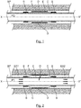
- metal tubular conduit BP known in the English terminology of " casing ", an isolation device.
- the BP line is placed inside a well A (it could however be a casing).
- BP line On the outer surface of the BP line are several cylindrical metal jackets, only one sleeve C being shown on the Figures 1 and 2 .
- the ends of the jacket C are sealingly attached to the face on the outer surface of the pipe BP, for example by means of rings or rings B.
- An expansion opening O is formed in the wall of the LP pipe (it can be provided several openings), so as to communicate the internal space of the BP pipe with the annular space formed between the wall of the BP pipe and the shirt C.
- the jacket C is covered over all or part of its length with a layer of elastically deformable material, for example elastomer, which constitutes a "sheet”, or “strip”, annular sealing D, a few millimeters thick.
- the liner may be covered with several sealing modules, spaced apart from one another.
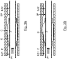
- the jacket C, and in particular the annular sealing ply D, is fixed against the internal wall of the formation F, at the level of the zone to be sealed, by radial expansion.
- This expansion operation is carried out, in the example illustrated, by hydroforming a fluid under pressure.
- the liner is shown in its initial state, when its wall is not yet deformed, the pressure inside the pipe BP being noted P0.
- the jacket C is expanded facing a cavity formed in the wall of the formation F.
- the behavior of the material constituting the jacket C is such that it is possible for the jacket C to continue to expand as long as P1 pressure is applied ( figure 3A ). If the cavity is large enough, the material of the jacket C can then reach its limit of elongation and the jacket C can break, as illustrated in FIG. figure 3B .
- the fluid coming from the pipe BP then spreads in the annular spaces EA1 and EA2 as illustrated by the arrows of the figure 3B .
- the opening O is not closed, a pressure drop occurs inside the BP line since the latter is in communication with the annular spaces EA1 and EA2.
- the patent document EP 2,607,613 A1 proposes a self-actuated shutter device which is in the form of a valve disposed in the communication opening between the inside of the pipe and the jacket. In case of rupture of the jacket, the valve moves from an open position, in which the fluid passes from the inside of the pipe inside the jacket, to a closed position, in which the fluid passage of the inside of the pipe inside the shirt is prevented.
- the valve is, in its closed position, applied against the body in which is formed the opening of communication so as to close the latter.
- the seal which is metal-on-metal, is not optimal.
- the valve moves under the effect of a spring to its open position.
- a radially expandable locking member which prevents the return of the valve to its open position.
- the locking element must ensure only the locking of the valve in its closed position.
- the invention therefore particularly aims to overcome all or part of these disadvantages of the prior art.
- the object of the invention is, in at least one embodiment, to provide a device for controlling the fluid passage which is efficient and which fully fulfills its function in case of rupture of the jacket of a device. insulation of part of a well or pipe.
- the shutter and sealing functions must be ensured whatever the liquid or gaseous medium in which the isolation device is used.
- the invention manages to fulfill all or part of these objectives by means of an isolation device of a portion of a well or pipe comprising a pipe provided on its outer face with at least one outer jacket surrounding said pipe, the ends of the jacket being sealingly attached to the outer surface of the pipe, the jacket being able to expand radially and sealingly against the inner wall of the well or pipe, at least one expansion pipe communicating the interior of the pipe with the space between the outer surface of the pipe and the inner wall of the jacket, the at least one expansion pipe comprising passage control means of fluid under pressure between the inside of the pipe and the space.
- the invention thus proposes a device for controlling the passage of fluid (or valve) between a tubular conduit, or " casing ", and a sleeve, or sleeve, that can be expanded by an isolation device for part of a well. or a pipe, such a control device being disposed in the expansion pipe connecting the " casing " to the inner space of the sleeve.
- the control device comprises a first shutter member, in the form of a valve, movable between at least one open position allowing the passage of fluid during expansion of the liner and a first closed position when the fluid intended to expand the jacket and coming from the " casing " is purged (that is to say once the shirt has been expanded).
- the first closure element can also take a second closed position (but not necessarily perfectly sealed), the second closed position being reached when the flow of fluid from the " casing " exceeds a predetermined threshold (typically 100l / min).
- control device comprises a second shutter element which, during the expansion phase of the jacket, is fixed.
- the second shutter member becomes movable and cooperates with the first shutter member to ensure an optimum seal between the inside and the outside. outside the pipe.
- This second shutter element thus constitutes a locking element which prevents the return of the first movable shutter element to its open position, in the event of rupture of the jacket, thus preventing the flow of fluid from the inside of the casing. "outward or outside the” casing “towards the inside of the” casing ".
- said second shutter member is a hollow element in which is mounted movably, along the longitudinal axis of said housing, said first shutter member.
- said second shutter member has an inlet communicating with the inside of the pipe and an outlet orifice communicating with the space, said first movable shutter member closing said orifice in the first closed position and said outlet in the second closed position.
- said second closure member disengaged from said housing, said first closure member and said second closure member cooperate by moving along the longitudinal axis of said housing so as to permanently close off said inlet port.
- said first shutter member is integral with at least one spring secured to said housing and tending to move said first shutter member to said inlet port.
- said second closure member is attached to a breakable portion of said housing.
- the attachment of said second shutter member to said breakable portion is implemented by welding.
- said breakable portion of said housing remains fixed to said second closure member when the latter closes from said housing.
- said housing has a zone of weakness connecting said breakable portion of said housing to the remainder of said housing, said zone of weakness comprising at least one lumen formed in the wall of said housing.
- the first movable shutter member carries first sealing means intended to come into contact with said second shutter member when the first movable shutter member closes said inlet orifice.
- said second closure member carries second sealing means coming into contact with the inner wall of said housing.
- said second closure member is fixed to said housing by gluing.
- said second closure member is fixed to said housing by at least one shear pin.
- said second closure member is held in said housing by a cover carrying breakable spring blades integral with said housing.
- the invention also relates to control means implemented in an isolation device as described above.
- the control device of the fluid passage according to the invention is intended to close / seal this expansion opening O in case of rupture of the jacket.
- control device of the fluid passage according to the invention is disposed in the pipe connecting the expansion opening O of the BP line to the inner space E of the jacket C.
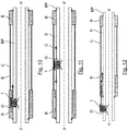
- control device of the fluid passage, or valve, 1 is disposed in the expansion opening O which opens into the welded end of an isolation device, that is to say in the configuration of the figure 10 .
- the control device of the fluid passage 1 is in the form of a sealed housing of substantially cylindrical shape.
- This housing consists of a hollow base 2 closed by a hollow plug 3A delimiting a cylindrical interior space.
- a first movable shutter member in the form of a valve 4, which can sealingly close the expansion opening O, so that the fluid passage is prohibited, in one sense as in the other.
- valve 4 In an intermediate position (for example that of the Figure 4A ), the valve 4 allows the passage of the pressurized fluid from the inside of the BP line to the inner space E of the jacket C.
- the valve 4 is biased downwards, that is to say towards the inside of the pipe BP, by a spring 8 which is fixed to the inner wall of the plug 3A.
- the valve, or piston, 4 is vertically movable along an axis perpendicular to the longitudinal axis XX 'of the BP line, as shown in FIG. figure 10 .
- the base 2 is screwed into the wall of the pipe, or " casing " BP.
- the seal between the base 2 and the pipe BP is ensured, for example, by a conventional commercial product which seals the threads and which hardens after tightening (for example, a composition which cures in the absence of oxygen, said anaerobic curing composition).
- the base 2 which is represented alone on the Figure 4B , is machined so as to present a zone of rupture or fragility (in the form of weak points) which is intended to break under a high pressure differential. More specifically, the base 2 is of hollow cylindrical shape and comprises an upper portion 201 breakable, a lower portion 206 and a central portion 204, the latter two portions being delimited on the outer surface of the base 2 by a circular rim 205 not continuous.
- the breakable zone comprises three oblong slots 202 formed in the wall of the base 2 between the upper portion 201 and the central portion 204. These slots 202 extend in a plane perpendicular to the longitudinal axis of the base 2 and are separated by material links 203 of small width / section which form break points, or weak points, intended to break under a high pressure differential of predetermined value.
- the valve 4 comprises three parts, namely a cylindrical first end 41 of diameter greater than a cylindrical second end 43, the two ends being connected by a cylindrical central portion 42 of greater diameter than the first cylindrical end 41.
- the first cylindrical end 41 of the valve 4 is integral with a cylindrical spiral spring 8 and is housed in the latter.
- the spring 8 is further secured to the plug 3A.
- the cylindrical second end 43 of the valve 4 is slidably guided in a cylindrical housing 132 formed in the base of a second closure member, hereinafter called base 13.
- the base 13 which is cylindrical in shape, is mounted in the base 2 and is fixed, by its upper part, to the base 2 by at least one weld which is implemented above the breaking points 203 of the base 2, on the inner wall of the upper portion 201.
- the weld or welds (tent) to block the translation of the base 13 relative to the base 2
- connection of the base 13 in the base 2 may be envisaged, particularly by gluing.
- the base 13 comprises an inlet orifice 131 of the annular fluid which is disposed in the base of the base 13 around the housing 132.
- the inlet orifice 131 is connected to the inside of the pipe BP. It is noted that the outside diameter and the height of the base 13 are slightly smaller than the inside diameter and the height respectively of the base 2.
- a ring 9 forming a stop is screwed into the upper part of the base 13.
- the inner part 92 of the ring 9 defines a fluid passage, called an outlet orifice, in which the first cylindrical end 41 of the valve 4 moves.
- the central part 42 of the valve 4 is able to move in the inner central portion 91 of the base 13, which forms a fluid passage.
- the central portion 42 of the valve 4 is adapted to abut against one face of the ring 9, defining a first seat, so as to close the outlet orifice 92 or against the base of the base 13, defining a second seat, so as to close the inlet port 131.
- the central portion 42 may further take at least one open intermediate position between these two closed positions where the valve 4 is "closed".
- An annular-shaped seal 5 is adhered in an annular recess of the central portion 42 of the valve 4 so that even when a large flow of fluid passes into the control device 1, the seal 5 is not expelled from its housing. .
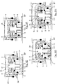
- FIG. Figure 5A The inflation or expansion phase of the sleeve C of the device 1 is illustrated in FIG. Figure 5A .
- the valve 4 opens.
- the central portion of the valve 4 is located between the base 13 and the stop 9, at a distance from these two elements.
- the fluid (schematically illustrated by arrows) can pass from the inside of the BP line to the inner space E of the jacket (not shown) through the inlet port 131, and then fluid passages 91, 92, 93 and finally the output port 94, the latter communicating with the inner space E of the sleeve (not shown).
- the flow of fluid in the control device 1 can create a significant pressure drop.
- the base 2 is dimensioned to resist this pressure drop. More precisely, the breaking points 203 are dimensioned so as not to break when subjected to this pressure drop.
- the purge phase is illustrated on the Figure 5B .
- the valve 4 moves downwardly sliding under the effect of the spring 8 (that is to say towards the base of the base 13), and closes.
- the central portion 42 of the valve 4 is pressed against the base of the base 13 thus closing the inlet port 131 sealingly through the seal 5 (it is the second closed position of the valve 4).
- a predetermined threshold " which is for example equal to 100 l / min
- the pressure drop at the passage of the valve 4 is sufficient to exceed the force of the spring 8 and come close the valve 4, as shown in the Figure 5C .
- valve 4 moves upwards (that is to say towards the ring 9) and its central portion 42 is pressed against the ring 9 preventing, or at least minimizing, the passage of the fluid from the passage 91 to the outlet orifice 92, and therefore from the BP line to the sleeve C, as shown by the arrows of the Figure 5C .
- the valve 4 is then in its first closed position which is not, in this example, completely sealed because any leakage would be minimal compared to the flow of fluid flowing through the pipe BP (it can be provided a seal for optimize tightness however).
- FIGS. 5D and 5E illustrate the activation of the locking function in the closed position of the valve 4 through the base 13, when the sleeve C is broken.
- the predetermined pressure typically between 50 and 100 bar
- the ring 9 being secured to the base 13 which moves upwards, the central portion 42 of the valve 4 is no longer in contact with the ring 9 but comes into contact with the base of the base 13 thus closing the inlet orifice 131, the seal being provided through joints 5 and 6 ( figure 5E ).
- the base 13 becomes movable and cooperates with the valve 4 to ensure an optimum seal between the inside and outside of the BP line.
- This base 13 thus constitutes a locking element which prevents the return of the valve 4 to its open position, in case of rupture of the jacket C.
- the figure 5F illustrates the purge phase.
- the spring 8 pushes the valve 4 and the base 13, which is now mobile, down (that is to say to the BP line).
- the central portion 42 of the valve 4 is always in contact with the base of the base 13 thus closing the inlet orifice 131, sealing being ensured during this movement by the joints 5 and 6.
- the assembly formed by the valve 4 and the base 13 is displaced, by pressure, in sliding in the base 2 until it abuts against the plug 3A , the seal being permanently ensured by the seals 5 and 6.
- the spring 8 is dimensioned so that the valve 4 keeps a sealed contact with the base of the base 13 during the movement of these two parts upwards (ie to say towards the stopper 3A).
- the fluid from the BP line can not pass from the inlet port 131 to the fluid passage 91.
- the base 13 disengages from the base 2, the base 13 cooperates with the valve 4 to close the fluid passage between the inside and the outside of the BP pipe, whatever the pressures inside and outside the BP line.
- control device of the fluid passage, or valve, 11 is also integrated in the welded end 110 of an isolation device, that is to say in the configuration of the figure 10 .
- the control device of the fluid passage, or valve, 11 is of substantially cylindrical shape and comprises a hollow base 12 closed by a hollow plug 13A delimiting a sealed or substantially sealed cylindrical interior space.
- the base 12 is screwed into the wall of the pipe, or " casing " BP.
- the first cylindrical end 141 of the valve 14 is integral with a spring 18 and is housed in the latter.
- the spring 18 is further secured to the plug 13A.
- the cylindrical second end 143 of the valve 14 is slidably guided in a cylindrical housing 1132 formed in the base of a second closure member, called a base 113.
- the base 113 which is cylindrical in shape, is fixedly mounted in the base 12 and comprises an inlet 1131 of the annular fluid which is disposed in the base of the base 113, around the housing 1132.
- the inlet port 1131 is connected to the inside of the BP line. It is noted that the outside diameter and the height of the base 113 are slightly smaller than the inside diameter and the height respectively of the base 12.
- the two cylindrical ends 141, 143 of the valve 14 are connected by a cylindrical central portion 142.
- a commercial adhesive blocks the translation of the base 113 relative to the base 12, this adhesive being applied in the game 112 formed between the base 12 and the base 113.
- two seals 17 whose function is to prevent the liquid glue from flowing in the game 112 are placed between the base 12 and the base 113 (the adhesive remaining liquid several hours after application).
- An annular-shaped seal 15 is adhered in an annular housing of the central portion 142 of the valve 14 so that even when a large flow of fluid passes into the closure device 11, the seal 15 is not expelled from its seal. housing.
- a ring 19 forming a seat for the valve 14 is screwed into the upper part of the base 113.
- the fluid can flow from the inside of the BP line to the jacket (not shown) through the inlet port 1131, then communication spaces 191, 192, 193 and finally the outlet port 194, the latter communicating with the interior space of the shirt.
- the inflation or expansion phase of the liner of the isolation device is illustrated on the Figure 9A .
- the valve 14 opens.
- the central portion of the valve 14 is located between the base 113 and the ring 19, substantially equidistant from these two elements.
- the fluid passes from the inlet port 1131 connected to the inside of the BP line to the outlet port 194 connected to the sleeve C. It is noted that the base 113 is fixedly mounted in the base 12.
- the clearance 112 between the base 12 and the base 113, the width and the diameter of the ring of adhesive applied in the game 112 (to block the translation of the base 113 relative to the base 12), and the shear resistance of this glue are dimensioned to withstand this loss of load and avoid shearing of the ring of glue (and thus the displacement of the base 113 relative to the base 12).
- the purge phase is illustrated on the Figure 9B .
- the valve 14 slidably moves downward (it closes under the effect of the spring 18), its central portion 142 coming to press against the base 113 then closing the orifice 1131 inlet sealingly through the seal 15.
- a pressure close to the end inflation pressure is kept inside the liner.
- the fluid from the jacket can not pass into the BP line.
- the large volume under pressure in the BP line, released by the rupture of the liner, will cause a large increase in the flow rate at the passage of the valve 14.
- the pressure drop at the passage of the valve 14 is sufficient to exceed the force of the spring 18 and come close the valve 14, as shown in the Figure 9C .
- the valve 14 moves upwards and is pressed against the ring 19 preventing or minimizing the passage of fluid from the BP line to the jacket as shown by the arrows.
- the Figures 9D and 9E illustrate the activation of the locking of the valve 14 in the closed position.
- a predetermined threshold typically between 50 and 100 bar
- the base 113 disengages from the base 12 and is pushed upwards, that is to say towards the ring 19, by the pressure ( Figure 9E ).
- the pressure to shear the glue is determined by the width, the diameter of the glue ring, the clearance 112 and the shear strength of the glue.
- the figure 9F illustrates the purge phase.
- the spring 18 pushes the valve 14 and the base 113 downwards (that is to say towards the BP line), the valve 14 keeping a tight contact with the base of the base 113. In this movement, the seals 15 and 16 always seal.
- the assembly formed by the valve 14 and the base 113 is pushed by the pressure in abutment to the plug 13A and the seal is permanently ensured by the seals 15 and 16.
- the spring 18 is dimensioned so that the valve 14 keeps a sealed contact with the base 113 during the upward movement, that is to say towards the plug 13A, of these two parts 14, 113 which cooperate.
- a third embodiment of a fluid passage control device, or valve, 21 is illustrated on the Figures 7A and 7B .
- the operation of the valve 21 is substantially identical to that of the valves 1, 11 described above.
- the valve 21 similarly comprises a base 22, a valve 24, a base 213 and a ring 29 which is fixedly mounted in the base 213.
- a ring 295 having in its center an opening 2951 for the passage of the upper portion 241 of the valve 24, and which is provided on its periphery with leaf spring 2952 spaced apart from each other.
- the ring 295 is fixed on the top of the base 22, shirt side, the ends of the spring blades 2952 being “clipped” in a groove machined in the base 22.
- the length and the thickness of the spring blades 2952 as well as the depth of the groove of the base 12 are calibrated to break at a determined pressure.
- the seal 25 is here of the type of flange seal.
- shear pins 396 are provided which are arranged (by screwing, for example) in radial holes formed around the periphery of the base 32. These shear pins 396 are integral with the base 313. The diameter and the material of the shear pins 396 are calibrated to break at a predetermined pressure.
Landscapes
- Life Sciences & Earth Sciences (AREA)
- Engineering & Computer Science (AREA)
- Geology (AREA)
- Mining & Mineral Resources (AREA)
- Physics & Mathematics (AREA)
- Environmental & Geological Engineering (AREA)
- Fluid Mechanics (AREA)
- General Life Sciences & Earth Sciences (AREA)
- Geochemistry & Mineralogy (AREA)
- Safety Valves (AREA)
Claims (16)
- Vorrichtung zum Isolieren eines Teils eines Bohrlochs oder einer Rohrleitung, umfassend eine Leitung (BP), die auf ihrer Außenseite mit mindestens einer äußeren Hülle versehen ist, die die Leitung (BP) umgibt, wobei die Enden der Hülle (C) dicht auf der Außenfläche der Leitung (BP) befestigt sind, wobei die Hülle (21) dazu geeignet ist, sich radial auszudehnen und sich dicht an die Innenwand des Bohrlochs oder der Rohrleitung anzulegen, wobei mindestens eine Ausdehnungsleitung (O) das Innere der Leitung (BP) mit dem Raum (E) in Verbindung bringt, der sich zwischen der Außenfläche der Leitung (BP) und der Innenwand der Hülle (C) befindet,
wobei die mindestens eine Ausdehnungsleitung (O) Mittel zur Steuerung des Durchgangs von druckbeaufschlagtem Fluid zwischen dem Inneren der Leitung (BP) und dem Raum (E) umfasst,
wobei die Vorrichtung dadurch gekennzeichnet ist, dass die Steuerungsmittel umfassen:- ein Gehäuse (2, 3A), das sich in der Ausdehnungsleitung (O) befindet und einerseits mit dem Inneren der Leitung (BP) und andererseits mit dem Raum (E) in Verbindung steht;- ein erstes Verschlussorgan (4), das sich in dem Gehäuse (2, 3A) befindet und zwischen einer ersten geschlossenen und dichten Position, in der das Fluid nicht von dem Raum (E) zu der Leitung (BP) zirkulieren kann, einer zweiten geschlossenen Position, die erreicht wird, wenn der Fluiddurchsatz von der Leitung (BP) zu dem Raum (E) eine vorbestimmte Grenze überschreitet, und mindestens einer offenen Zwischenposition zwischen diesen zwei geschlossenen Positionen, in der das Abfließen des Fluids von der Leitung (BP) zu dem Raum (E) gestattet ist, beweglich ist;- ein zweites Verschlussorgan (13), das fest in dem Gehäuse (2, 3A) befestigt und eingerichtet ist, um sich von dem Gehäuse (2, 3A) zu lösen, wenn das erste Verschlussorgan (4) in der zweiten geschlossenen Position ist, und wenn der Druckunterschied zwischen der Leitung (BP) und dem Raum (E) eine vorbestimmte Grenze überschreitet, um mit dem ersten Verschlussorgan (4) zusammenzuwirken und das Abfließen des Fluids von der Leitung (BP) zu dem Raum (E) oder von dem Raum (E) zu der Leitung (BP) zu verhindern, unabhängig von dem Druck innerhalb oder außerhalb der Leitung (BP). - Isolierungsvorrichtung nach Anspruch 1, dadurch gekennzeichnet, dass das zweite Verschlussorgan (13) ein hohles Element ist, in dem entlang der Längsachse des Gehäuses (2, 3A) das erste Verschlussorgan (4) beweglich montiert ist.
- Isolierungsvorrichtung nach Anspruch 1 oder 2, dadurch gekennzeichnet, dass das zweite Verschlussorgan (13) eine Eingangsöffnung (131), die mit dem Inneren der Leitung (BP) in Verbindung steht, und eine Ausgangsöffnung (92) aufweist, die mit dem Raum (E) in Verbindung steht, wobei das erste bewegliche Verschlussorgan (4) die Eingangsöffnung (131) in der ersten geschlossenen Position und die Ausgangsöffnung (92) in der zweiten geschlossenen Position verschließt.
- Isolierungsvorrichtung nach Anspruch 3, dadurch gekennzeichnet, dass, wenn das zweite Verschlussorgan (13) von dem Gehäuse (2, 3A) gelöst ist, das erste Verschlussorgan (4) und das zweite Verschlussorgan (13) zusammenwirken, indem sie sich entlang der Längsachse des Gehäuses (2, 3A) verlagern, um die Eingangsöffnung (131) dauerhaft zu verschließen.
- Isolierungsvorrichtung nach Anspruch 3 oder 4, dadurch gekennzeichnet, dass das erste Verschlussorgan (4) mit mindestens einer Feder (8) verbunden ist, die mit dem Gehäuse (2, 3A) verbunden ist und dahingehend wirkt, das erste Verschlussorgan (4) gegenüber der Eingangsöffnung (131) zu verlagern.
- Isolierungsvorrichtung nach einem der Ansprüche 1 bis 5, dadurch gekennzeichnet, dass das zweite Verschlussorgan (13) an einem vom Gehäuse (2, 3A) trennbaren Abschnitt befestigt ist.
- Isolierungsvorrichtung nach Anspruch 6, dadurch gekennzeichnet, dass die Befestigung des zweiten Verschlussorgans (13) an dem trennbaren Abschnitt mittels Schweißen umgesetzt ist.
- Isolierungsvorrichtung nach Anspruch 6 oder 7, dadurch gekennzeichnet, dass der vom Gehäuse (2, 3A) trennbare Abschnitt an dem zweiten Verschlussorgan (13) befestigt bleibt, wenn sich dieser letztgenannte vom Gehäuse (2, 3A) löst.
- Isolierungsvorrichtung nach einem der Ansprüche 6 bis 8, dadurch gekennzeichnet, dass das Gehäuse (2, 3A) eine Fragilitätszone aufweist, die den vom Gehäuse (2, 3A) trennbaren Abschnitt mit dem Rest des Gehäuses (2, 3A) verbindet, wobei die Fragilitätszone mindestens eine Öffnung umfasst, die in der Wand des Gehäuses (2, 3A) vorgesehen ist.
- Isolierungsvorrichtung nach einem der Ansprüche 2 bis 9, dadurch gekennzeichnet, dass das erste bewegliche Verschlussorgan (4) erste Dichtungsmittel (5) trägt, die dazu bestimmt sind, mit dem zweiten Verschlussorgan (13) in Kontakt zu kommen, wenn das erste bewegliche Verschlussorgan (4) die Eingangsöffnung (131) verschließt.
- Isolierungsvorrichtung nach einem der Ansprüche 1 bis 10, dadurch gekennzeichnet, dass das zweite Verschlussorgan (13) zweite Dichtungsmittel (6) trägt, die mit der Innenwand des Gehäuses (2, 3A) in Kontakt gelangen.
- Isolierungsvorrichtung nach einem der Ansprüche 1 bis 11, dadurch gekennzeichnet, dass das zweite Verschlussorgan (13) am Gehäuse (2, 3A) mittels Kleben befestigt ist.
- Isolierungsvorrichtung nach einem der Ansprüche 1 bis 11, dadurch gekennzeichnet, dass das zweite Verschlussorgan (13) am Gehäuse (2, 3A) mittels mindestens eines Scherstifts befestigt ist.
- Isolierungsvorrichtung nach einem der Ansprüche 1 bis 11, dadurch gekennzeichnet, dass das zweite Verschlussorgan (13) in dem Gehäuse (2, 3A) durch eine Kappe gehalten wird, die mit dem Gehäuse (2, 3A) verbundene trennbare Federblätter trägt.
- Isoliervorrichtung nach einem der Ansprüche 1 bis 14, dadurch gekennzeichnet, dass die Steuerungsmittel zumindest teilweise angeordnet sind:- in einer Öffnung (O), die in der Wand er Leitung (BP) gegenüber der Hülle (C) vorgesehen ist, oder- in den Befestigungsmitteln der Hülle (C) auf der Leitung (BP), oder auch- außerhalb der Hülle (C) zwischen der Wand der Leitung (BP) und den Befestigungsmitteln der Hülle (C).
- Steuerungsmittel, die in einer Vorrichtung zum Isolieren eines Teils eines Bohrlochs oder einer Rohrleitung nach einem der Ansprüche 1 bis 15 eingesetzt werden, wobei die Isolierungsvorrichtung eine Leitung (BP) umfasst, die auf ihrer Außenseite mit mindestens einer äußeren Hülle versehen ist, die die Leitung (BP) umgibt, wobei die Enden der Hülle (C) dicht auf der Außenfläche der Leitung (BP) befestigt sind, wobei die Hülle (21) dazu geeignet ist, sich radial auszudehnen und sich dicht an die Innenwand des Bohrlochs oder der Rohrleitung anzulegen, wobei mindestens eine Ausdehnungsleitung (O) das Innere der Leitung (BP) mit dem Raum (E) in Verbindung bringt, der sich zwischen der Außenfläche der Leitung (BP) und der Innenwand der Hülle (C) befindet,
wobei die mindestens eine Ausdehnungsleitung (O) Mittel zur Steuerung des Durchgangs von druckbeaufschlagtem Fluid zwischen dem Inneren der Leitung (BP) und dem Raum (E) umfasst,
dadurch gekennzeichnet ist, dass die Steuerungsmittel umfassen:- ein Gehäuse (2, 3A), das sich in der Ausdehnungsleitung (O) befindet und einerseits mit dem Inneren der Leitung (BP) und andererseits mit dem Raum (E) in Verbindung steht;- ein erstes Verschlussorgan(4), das sich in dem Gehäuse (2, 3A) befindet und zwischen einer ersten geschlossenen und dichten Position, in der das Fluid nicht von dem Raum (E) zu der Leitung (BP) zirkulieren kann, einer zweiten geschlossenen Position, die erreicht wird, wenn der Fluiddurchsatz von der Leitung (BP) zu dem Raum (E) eine vorbestimmte Grenze überschreitet, und mindestens einer offenen Zwischenposition zwischen diesen zwei geschlossenen Positionen, in der das Abfließen des Fluids von der Leitung (BP) zu dem Raum (E) gestattet ist, beweglich ist;- ein zweites Verschlussorgan (13), das fest in dem Gehäuse (2, 3A) befestigt und eingerichtet ist, um sich von dem Gehäuse (2, 3A) zu lösen, wenn das erste Verschlussorgan (4) in der zweiten geschlossenen Position ist, und wenn der Druckunterschied zwischen der Leitung (BP) und dem Raum (E) eine vorbestimmte Grenze überschreitet, um mit dem ersten Verschlussorgan (4) zusammenzuwirken und das Abfließen des Fluids von der Leitung (BP) zu dem Raum (E) oder von dem Raum (E) zu der Leitung (BP) zu verhindern, unabhängig von dem Druck innerhalb oder außerhalb der Leitung (BP).
Applications Claiming Priority (2)
| Application Number | Priority Date | Filing Date | Title |
|---|---|---|---|
| FR1463217A FR3030610B1 (fr) | 2014-12-23 | 2014-12-23 | Dispositif d’isolation d'une partie d'un puits ou d’une canalisation et moyens de commande mis en oeuvre dans un tel dispositif d'isolation |
| PCT/EP2015/081080 WO2016102620A1 (fr) | 2014-12-23 | 2015-12-22 | Dispositif d'isolation d'une partie d'un puits ou d'une canalisation et moyens de commande mis en oeuvre dans un tel dispositif d'isolation |
Publications (2)
| Publication Number | Publication Date |
|---|---|
| EP3237723A1 EP3237723A1 (de) | 2017-11-01 |
| EP3237723B1 true EP3237723B1 (de) | 2018-09-26 |
Family
ID=52692868
Family Applications (1)
| Application Number | Title | Priority Date | Filing Date |
|---|---|---|---|
| EP15819827.5A Not-in-force EP3237723B1 (de) | 2014-12-23 | 2015-12-22 | Vorrichtung zum isolieren eines teils eines bohrlochs oder einer rohrleitung sowie in solch einer isolierungsvorrichtung implementierte steuerungseinrichtungen |
Country Status (3)
| Country | Link |
|---|---|
| EP (1) | EP3237723B1 (de) |
| FR (1) | FR3030610B1 (de) |
| WO (1) | WO2016102620A1 (de) |
Family Cites Families (4)
| Publication number | Priority date | Publication date | Assignee | Title |
|---|---|---|---|---|
| US3776308A (en) * | 1971-08-17 | 1973-12-04 | Lynes Inc | Safety valve arrangement for controlling communication between the interior and exterior of a tubular member |
| US4586526A (en) * | 1983-11-18 | 1986-05-06 | N. J. McAllister Petroleum Industries, Inc. | Arrangement for controlling communication between a tubular member and an inflatable element supported on the tubular member in a well bore |
| EP2607613A1 (de) * | 2011-12-21 | 2013-06-26 | Welltec A/S | Ringförmige Abgrenzung in einer selbst auslösenden Vorrichtung |
| FR3003891B1 (fr) * | 2013-03-27 | 2015-04-03 | Saltel Ind | Dispositif de commande et d'isolation d'un outil en forme de chemise expansible pour l'isolation de zones dans un puits |
-
2014
- 2014-12-23 FR FR1463217A patent/FR3030610B1/fr not_active Expired - Fee Related
-
2015
- 2015-12-22 EP EP15819827.5A patent/EP3237723B1/de not_active Not-in-force
- 2015-12-22 WO PCT/EP2015/081080 patent/WO2016102620A1/fr not_active Ceased
Non-Patent Citations (1)
| Title |
|---|
| None * |
Also Published As
| Publication number | Publication date |
|---|---|
| EP3237723A1 (de) | 2017-11-01 |
| FR3030610B1 (fr) | 2017-01-13 |
| WO2016102620A1 (fr) | 2016-06-30 |
| FR3030610A1 (fr) | 2016-06-24 |
Similar Documents
| Publication | Publication Date | Title |
|---|---|---|
| EP3167148B1 (de) | Aufweitbares röhrenförmiges element zur aufnahme von einer oder mehreren aufblasbaren dichtungen | |
| EP0867596B1 (de) | Gewindeverbinder für Rohre | |
| CA2841797C (fr) | Dispositif d'isolation d'une partie d'un puits | |
| EP0536256B1 (de) | Radial verformbares rohr mit mehreren lösbar verbundenen elementen | |
| EP0325541B1 (de) | Vorrichtung und Verfahren zum Isolieren produzierender Schichten in einer Bohrung | |
| EP2771598B1 (de) | Isolierventil | |
| FR3003891A1 (fr) | Dispositif de commande et d'isolation d'un outil en forme de chemise expansible pour l'isolation de zones dans un puits | |
| FR2841626A1 (fr) | Joint filete tubulaire renforce pour etancheite amelioree apres expansion plastique | |
| EP3092368B1 (de) | Isoliervorrichtung für ein bohrloch | |
| WO2017009460A1 (fr) | Dispositif d'isolation pour puits avec un disque de rupture | |
| WO2017009463A1 (fr) | Dispositif de protection d'un pion dégradable pour système d'isolation dans une barrière annulaire | |
| CA2997795A1 (fr) | Bouchon de test en pression pour composant filete tubulaire superieur | |
| FR2841628A1 (fr) | Soupape a clapet incurve | |
| EP1328744A1 (de) | Ausgabekopf zur ausgabe einer flüssigkeit und spender mit einem solchen kopf | |
| WO2009103629A1 (fr) | Procede et dispositif de tubage d'une portion de puits foree | |
| EP0489137B1 (de) | Steigrohr mit einer integrierten hydraulischen leitung | |
| FR2570793A1 (fr) | Soupape d'injection chimique actionnee par piston | |
| FR3030610A1 (fr) | Dispositif d’isolation d'une partie d'un puits ou d’une canalisation et moyens de commande mis en oeuvre dans un tel dispositif d'isolation | |
| EP3320174B1 (de) | Vorrichtung zum zementieren eines rohres in ein bohrloch und entsprechendes zementierungsverfahren | |
| FR2790509A1 (fr) | Dispositif de controle de debit en fond de puits, a chemise obturatrice exterieure | |
| FR2503320A1 (fr) | Dispositif perfectionne pour liberer de maniere sure la pression regnant dans la cavite d'une vanne en cas d'incendie dans le voisinage de la vanne | |
| FR2468813A1 (fr) | Soupape de surete souterraine commandee de la surface | |
| FR2878586A1 (fr) | Ensemble d'entrainement a reservoir etanche | |
| CA2314770A1 (fr) | Dispositif anti-retour | |
| FR2546962A1 (fr) | Garniture d'etancheite pour separation de zones dans un puits de forage |
Legal Events
| Date | Code | Title | Description |
|---|---|---|---|
| PUAI | Public reference made under article 153(3) epc to a published international application that has entered the european phase |
Free format text: ORIGINAL CODE: 0009012 |
|
| 17P | Request for examination filed |
Effective date: 20170523 |
|
| AK | Designated contracting states |
Kind code of ref document: A1 Designated state(s): AL AT BE BG CH CY CZ DE DK EE ES FI FR GB GR HR HU IE IS IT LI LT LU LV MC MK MT NL NO PL PT RO RS SE SI SK SM TR |
|
| AX | Request for extension of the european patent |
Extension state: BA ME |
|
| RIN1 | Information on inventor provided before grant (corrected) |
Inventor name: ROSELIER, SAMUEL Inventor name: LE DUC, JULIE Inventor name: NEVEU, ROMAIN Inventor name: TANGUY, GWENAEL |
|
| DAV | Request for validation of the european patent (deleted) | ||
| DAX | Request for extension of the european patent (deleted) | ||
| GRAP | Despatch of communication of intention to grant a patent |
Free format text: ORIGINAL CODE: EPIDOSNIGR1 |
|
| INTG | Intention to grant announced |
Effective date: 20180416 |
|
| GRAS | Grant fee paid |
Free format text: ORIGINAL CODE: EPIDOSNIGR3 |
|
| GRAA | (expected) grant |
Free format text: ORIGINAL CODE: 0009210 |
|
| AK | Designated contracting states |
Kind code of ref document: B1 Designated state(s): AL AT BE BG CH CY CZ DE DK EE ES FI FR GB GR HR HU IE IS IT LI LT LU LV MC MK MT NL NO PL PT RO RS SE SI SK SM TR |
|
| REG | Reference to a national code |
Ref country code: GB Ref legal event code: FG4D Free format text: NOT ENGLISH |
|
| REG | Reference to a national code |
Ref country code: CH Ref legal event code: EP |
|
| REG | Reference to a national code |
Ref country code: AT Ref legal event code: REF Ref document number: 1046243 Country of ref document: AT Kind code of ref document: T Effective date: 20181015 |
|
| REG | Reference to a national code |
Ref country code: IE Ref legal event code: FG4D Free format text: LANGUAGE OF EP DOCUMENT: FRENCH |
|
| REG | Reference to a national code |
Ref country code: DE Ref legal event code: R096 Ref document number: 602015017269 Country of ref document: DE |
|
| REG | Reference to a national code |
Ref country code: NL Ref legal event code: MP Effective date: 20180926 |
|
| PG25 | Lapsed in a contracting state [announced via postgrant information from national office to epo] |
Ref country code: LT Free format text: LAPSE BECAUSE OF FAILURE TO SUBMIT A TRANSLATION OF THE DESCRIPTION OR TO PAY THE FEE WITHIN THE PRESCRIBED TIME-LIMIT Effective date: 20180926 Ref country code: RS Free format text: LAPSE BECAUSE OF FAILURE TO SUBMIT A TRANSLATION OF THE DESCRIPTION OR TO PAY THE FEE WITHIN THE PRESCRIBED TIME-LIMIT Effective date: 20180926 Ref country code: FI Free format text: LAPSE BECAUSE OF FAILURE TO SUBMIT A TRANSLATION OF THE DESCRIPTION OR TO PAY THE FEE WITHIN THE PRESCRIBED TIME-LIMIT Effective date: 20180926 Ref country code: SE Free format text: LAPSE BECAUSE OF FAILURE TO SUBMIT A TRANSLATION OF THE DESCRIPTION OR TO PAY THE FEE WITHIN THE PRESCRIBED TIME-LIMIT Effective date: 20180926 Ref country code: NO Free format text: LAPSE BECAUSE OF FAILURE TO SUBMIT A TRANSLATION OF THE DESCRIPTION OR TO PAY THE FEE WITHIN THE PRESCRIBED TIME-LIMIT Effective date: 20181226 Ref country code: GR Free format text: LAPSE BECAUSE OF FAILURE TO SUBMIT A TRANSLATION OF THE DESCRIPTION OR TO PAY THE FEE WITHIN THE PRESCRIBED TIME-LIMIT Effective date: 20181227 Ref country code: BG Free format text: LAPSE BECAUSE OF FAILURE TO SUBMIT A TRANSLATION OF THE DESCRIPTION OR TO PAY THE FEE WITHIN THE PRESCRIBED TIME-LIMIT Effective date: 20181226 |
|
| REG | Reference to a national code |
Ref country code: LT Ref legal event code: MG4D |
|
| PG25 | Lapsed in a contracting state [announced via postgrant information from national office to epo] |
Ref country code: LV Free format text: LAPSE BECAUSE OF FAILURE TO SUBMIT A TRANSLATION OF THE DESCRIPTION OR TO PAY THE FEE WITHIN THE PRESCRIBED TIME-LIMIT Effective date: 20180926 Ref country code: HR Free format text: LAPSE BECAUSE OF FAILURE TO SUBMIT A TRANSLATION OF THE DESCRIPTION OR TO PAY THE FEE WITHIN THE PRESCRIBED TIME-LIMIT Effective date: 20180926 Ref country code: AL Free format text: LAPSE BECAUSE OF FAILURE TO SUBMIT A TRANSLATION OF THE DESCRIPTION OR TO PAY THE FEE WITHIN THE PRESCRIBED TIME-LIMIT Effective date: 20180926 |
|
| REG | Reference to a national code |
Ref country code: AT Ref legal event code: MK05 Ref document number: 1046243 Country of ref document: AT Kind code of ref document: T Effective date: 20180926 |
|
| PG25 | Lapsed in a contracting state [announced via postgrant information from national office to epo] |
Ref country code: IT Free format text: LAPSE BECAUSE OF FAILURE TO SUBMIT A TRANSLATION OF THE DESCRIPTION OR TO PAY THE FEE WITHIN THE PRESCRIBED TIME-LIMIT Effective date: 20180926 Ref country code: ES Free format text: LAPSE BECAUSE OF FAILURE TO SUBMIT A TRANSLATION OF THE DESCRIPTION OR TO PAY THE FEE WITHIN THE PRESCRIBED TIME-LIMIT Effective date: 20180926 Ref country code: RO Free format text: LAPSE BECAUSE OF FAILURE TO SUBMIT A TRANSLATION OF THE DESCRIPTION OR TO PAY THE FEE WITHIN THE PRESCRIBED TIME-LIMIT Effective date: 20180926 Ref country code: NL Free format text: LAPSE BECAUSE OF FAILURE TO SUBMIT A TRANSLATION OF THE DESCRIPTION OR TO PAY THE FEE WITHIN THE PRESCRIBED TIME-LIMIT Effective date: 20180926 Ref country code: CZ Free format text: LAPSE BECAUSE OF FAILURE TO SUBMIT A TRANSLATION OF THE DESCRIPTION OR TO PAY THE FEE WITHIN THE PRESCRIBED TIME-LIMIT Effective date: 20180926 Ref country code: IS Free format text: LAPSE BECAUSE OF FAILURE TO SUBMIT A TRANSLATION OF THE DESCRIPTION OR TO PAY THE FEE WITHIN THE PRESCRIBED TIME-LIMIT Effective date: 20190126 Ref country code: AT Free format text: LAPSE BECAUSE OF FAILURE TO SUBMIT A TRANSLATION OF THE DESCRIPTION OR TO PAY THE FEE WITHIN THE PRESCRIBED TIME-LIMIT Effective date: 20180926 Ref country code: EE Free format text: LAPSE BECAUSE OF FAILURE TO SUBMIT A TRANSLATION OF THE DESCRIPTION OR TO PAY THE FEE WITHIN THE PRESCRIBED TIME-LIMIT Effective date: 20180926 Ref country code: PL Free format text: LAPSE BECAUSE OF FAILURE TO SUBMIT A TRANSLATION OF THE DESCRIPTION OR TO PAY THE FEE WITHIN THE PRESCRIBED TIME-LIMIT Effective date: 20180926 |
|
| PG25 | Lapsed in a contracting state [announced via postgrant information from national office to epo] |
Ref country code: SK Free format text: LAPSE BECAUSE OF FAILURE TO SUBMIT A TRANSLATION OF THE DESCRIPTION OR TO PAY THE FEE WITHIN THE PRESCRIBED TIME-LIMIT Effective date: 20180926 Ref country code: SM Free format text: LAPSE BECAUSE OF FAILURE TO SUBMIT A TRANSLATION OF THE DESCRIPTION OR TO PAY THE FEE WITHIN THE PRESCRIBED TIME-LIMIT Effective date: 20180926 Ref country code: PT Free format text: LAPSE BECAUSE OF FAILURE TO SUBMIT A TRANSLATION OF THE DESCRIPTION OR TO PAY THE FEE WITHIN THE PRESCRIBED TIME-LIMIT Effective date: 20190126 |
|
| REG | Reference to a national code |
Ref country code: DE Ref legal event code: R097 Ref document number: 602015017269 Country of ref document: DE |
|
| REG | Reference to a national code |
Ref country code: DE Ref legal event code: R119 Ref document number: 602015017269 Country of ref document: DE |
|
| PG25 | Lapsed in a contracting state [announced via postgrant information from national office to epo] |
Ref country code: DK Free format text: LAPSE BECAUSE OF FAILURE TO SUBMIT A TRANSLATION OF THE DESCRIPTION OR TO PAY THE FEE WITHIN THE PRESCRIBED TIME-LIMIT Effective date: 20180926 |
|
| REG | Reference to a national code |
Ref country code: CH Ref legal event code: PL |
|
| PLBE | No opposition filed within time limit |
Free format text: ORIGINAL CODE: 0009261 |
|
| STAA | Information on the status of an ep patent application or granted ep patent |
Free format text: STATUS: NO OPPOSITION FILED WITHIN TIME LIMIT |
|
| PG25 | Lapsed in a contracting state [announced via postgrant information from national office to epo] |
Ref country code: MC Free format text: LAPSE BECAUSE OF FAILURE TO SUBMIT A TRANSLATION OF THE DESCRIPTION OR TO PAY THE FEE WITHIN THE PRESCRIBED TIME-LIMIT Effective date: 20180926 Ref country code: LU Free format text: LAPSE BECAUSE OF NON-PAYMENT OF DUE FEES Effective date: 20181222 |
|
| 26N | No opposition filed |
Effective date: 20190627 |
|
| REG | Reference to a national code |
Ref country code: IE Ref legal event code: MM4A |
|
| REG | Reference to a national code |
Ref country code: BE Ref legal event code: MM Effective date: 20181231 |
|
| PG25 | Lapsed in a contracting state [announced via postgrant information from national office to epo] |
Ref country code: IE Free format text: LAPSE BECAUSE OF NON-PAYMENT OF DUE FEES Effective date: 20181222 Ref country code: DE Free format text: LAPSE BECAUSE OF NON-PAYMENT OF DUE FEES Effective date: 20190702 Ref country code: FR Free format text: LAPSE BECAUSE OF NON-PAYMENT OF DUE FEES Effective date: 20181231 Ref country code: SI Free format text: LAPSE BECAUSE OF FAILURE TO SUBMIT A TRANSLATION OF THE DESCRIPTION OR TO PAY THE FEE WITHIN THE PRESCRIBED TIME-LIMIT Effective date: 20180926 |
|
| PG25 | Lapsed in a contracting state [announced via postgrant information from national office to epo] |
Ref country code: BE Free format text: LAPSE BECAUSE OF NON-PAYMENT OF DUE FEES Effective date: 20181231 |
|
| PG25 | Lapsed in a contracting state [announced via postgrant information from national office to epo] |
Ref country code: LI Free format text: LAPSE BECAUSE OF NON-PAYMENT OF DUE FEES Effective date: 20181231 Ref country code: CH Free format text: LAPSE BECAUSE OF NON-PAYMENT OF DUE FEES Effective date: 20181231 |
|
| PG25 | Lapsed in a contracting state [announced via postgrant information from national office to epo] |
Ref country code: MT Free format text: LAPSE BECAUSE OF FAILURE TO SUBMIT A TRANSLATION OF THE DESCRIPTION OR TO PAY THE FEE WITHIN THE PRESCRIBED TIME-LIMIT Effective date: 20180926 |
|
| PG25 | Lapsed in a contracting state [announced via postgrant information from national office to epo] |
Ref country code: TR Free format text: LAPSE BECAUSE OF FAILURE TO SUBMIT A TRANSLATION OF THE DESCRIPTION OR TO PAY THE FEE WITHIN THE PRESCRIBED TIME-LIMIT Effective date: 20180926 |
|
| PG25 | Lapsed in a contracting state [announced via postgrant information from national office to epo] |
Ref country code: MK Free format text: LAPSE BECAUSE OF NON-PAYMENT OF DUE FEES Effective date: 20180926 Ref country code: CY Free format text: LAPSE BECAUSE OF FAILURE TO SUBMIT A TRANSLATION OF THE DESCRIPTION OR TO PAY THE FEE WITHIN THE PRESCRIBED TIME-LIMIT Effective date: 20180926 Ref country code: HU Free format text: LAPSE BECAUSE OF FAILURE TO SUBMIT A TRANSLATION OF THE DESCRIPTION OR TO PAY THE FEE WITHIN THE PRESCRIBED TIME-LIMIT; INVALID AB INITIO Effective date: 20151222 |
|
| GBPC | Gb: european patent ceased through non-payment of renewal fee |
Effective date: 20191222 |
|
| PG25 | Lapsed in a contracting state [announced via postgrant information from national office to epo] |
Ref country code: GB Free format text: LAPSE BECAUSE OF NON-PAYMENT OF DUE FEES Effective date: 20191222 |