EP3092885A1 - Faucheuse - Google Patents
Faucheuse Download PDFInfo
- Publication number
- EP3092885A1 EP3092885A1 EP16001065.8A EP16001065A EP3092885A1 EP 3092885 A1 EP3092885 A1 EP 3092885A1 EP 16001065 A EP16001065 A EP 16001065A EP 3092885 A1 EP3092885 A1 EP 3092885A1
- Authority
- EP
- European Patent Office
- Prior art keywords
- mower
- assembly
- fan
- suction unit
- mower assembly
- Prior art date
- Legal status (The legal status is an assumption and is not a legal conclusion. Google has not performed a legal analysis and makes no representation as to the accuracy of the status listed.)
- Granted
Links
Images

Classifications
-
- A—HUMAN NECESSITIES
- A01—AGRICULTURE; FORESTRY; ANIMAL HUSBANDRY; HUNTING; TRAPPING; FISHING
- A01D—HARVESTING; MOWING
- A01D34/00—Mowers; Mowing apparatus of harvesters
- A01D34/01—Mowers; Mowing apparatus of harvesters characterised by features relating to the type of cutting apparatus
- A01D34/412—Mowers; Mowing apparatus of harvesters characterised by features relating to the type of cutting apparatus having rotating cutters
- A01D34/63—Mowers; Mowing apparatus of harvesters characterised by features relating to the type of cutting apparatus having rotating cutters having cutters rotating about a vertical axis
- A01D34/82—Other details
-
- A—HUMAN NECESSITIES
- A01—AGRICULTURE; FORESTRY; ANIMAL HUSBANDRY; HUNTING; TRAPPING; FISHING
- A01D—HARVESTING; MOWING
- A01D34/00—Mowers; Mowing apparatus of harvesters
- A01D34/01—Mowers; Mowing apparatus of harvesters characterised by features relating to the type of cutting apparatus
- A01D34/412—Mowers; Mowing apparatus of harvesters characterised by features relating to the type of cutting apparatus having rotating cutters
- A01D34/63—Mowers; Mowing apparatus of harvesters characterised by features relating to the type of cutting apparatus having rotating cutters having cutters rotating about a vertical axis
- A01D34/64—Mowers; Mowing apparatus of harvesters characterised by features relating to the type of cutting apparatus having rotating cutters having cutters rotating about a vertical axis mounted on a vehicle, e.g. a tractor, or drawn by an animal or a vehicle
- A01D34/66—Mowers; Mowing apparatus of harvesters characterised by features relating to the type of cutting apparatus having rotating cutters having cutters rotating about a vertical axis mounted on a vehicle, e.g. a tractor, or drawn by an animal or a vehicle with two or more cutters
- A01D34/664—Disc cutter bars
-
- A—HUMAN NECESSITIES
- A01—AGRICULTURE; FORESTRY; ANIMAL HUSBANDRY; HUNTING; TRAPPING; FISHING
- A01D—HARVESTING; MOWING
- A01D34/00—Mowers; Mowing apparatus of harvesters
- A01D34/01—Mowers; Mowing apparatus of harvesters characterised by features relating to the type of cutting apparatus
- A01D34/412—Mowers; Mowing apparatus of harvesters characterised by features relating to the type of cutting apparatus having rotating cutters
- A01D34/63—Mowers; Mowing apparatus of harvesters characterised by features relating to the type of cutting apparatus having rotating cutters having cutters rotating about a vertical axis
- A01D34/73—Cutting apparatus
-
- A—HUMAN NECESSITIES
- A01—AGRICULTURE; FORESTRY; ANIMAL HUSBANDRY; HUNTING; TRAPPING; FISHING
- A01D—HARVESTING; MOWING
- A01D2101/00—Lawn-mowers
Definitions
- the invention relates to a mowing machine for mowing agricultural stalk and sheet material according to the preamble of claim 1.
- Such mowers are known from the prior art in various embodiments and serve to standing on a field or meadow surface, agricultural stalk and Blattgut to cut it to then store it in a swath form required for the further harvesting process or to support an improved drying of the crop in a uniform layer over the entire working width.
- the mower is equipped with cutting members, which are driven at a high peripheral speed around an approximately vertical axis circumferentially. At least two cutting members associated cutting blade cut off the grass or the like.
- a rotary mower has become known in which mounted on a machine frame mower plates are used for the mowing process.
- To solve the problem with the directed in the direction of travel and working air flow is proposed to attach to the bottom of the mower disc air conveyor elements which are designed so that a radially inward air flow is formed and the air flow generated through passage openings in the mower disc from the bottom of the Mähtellers can get to its top.
- a shutdown of the lack of the still standing stalk and sheet material directed air flow during mowing operation, however, is not yet reached, since the mowing plates are also suitable at its top to build up air currents.
- the object of the invention is therefore to provide a mowing machine for mowing agricultural stalk and sheet material, in which the known deficiencies of the prior art are reliably avoided and thus under the many different conditions of use, a clean cut can be achieved.
- a mowing machine for mowing agricultural stalk or sheet material with at least two circumferentially driven about an axis vertically driven cutting members, the at least one, provided in the working and operating position ground near, on its outer periphery with at least two cutting blades Rotary body and are mounted in a direction transverse to the direction of travel and working on a mower assembly, the mower assembly is supported in the working and operating position via a frame assembly on the ground and at least partially surrounded by a protective and cover assembly, wherein the mower assembly a is associated with active suction unit, which is adapted to one of the To redirect mower assembly in the direction of the still standing stalk and sheet material directed air flow in a direction in which the still standing stalk and sheet material is no longer acted upon by the air flow.
- the invention thus proposes a mowing machine for mowing agricultural stem or leaf material, in which the mower assembly is associated with an active suction unit.
- This suction unit is adapted to deflect air currents, which prevail below a mower assembly at least partially surrounding protective and cover assembly and are directed towards the mowed Halm- or sheet material to redirect in a direction in which the mowed Halm- or sheet material through the air flow is applied.
- This reversal of the air flow according to the invention has the consequence that the mulch or sheet material to be milled is no longer moved away or pushed back in the direction of travel and working when mowing.
- a field or meadow area with the same length, remaining on the field or meadow surface stubble.
- the deflection of the air flow takes place in this case in that the suction unit assigned to the mower assembly sucks a sufficiently large amount of air out of a region which extends above the cutting bodies designed as a rotating body and reaches as far as a protective and cover assembly at least partially surrounding the mower assembly.
- the suction unit assigned to the mower assembly sucks a sufficiently large amount of air out of a region which extends above the cutting bodies designed as a rotating body and reaches as far as a protective and cover assembly at least partially surrounding the mower assembly.
- the mower assembly with the circumferentially driven cutting members at least from the top surrounded by a protective and cover assembly. This may be an approximately box-shaped sheet metal cover and / or a protective cloth arrangements that creates in terms of a sufficient protective effect against flying stones or the like.
- the air flow discharged from the surrounding area of the mower group is discharged into a region behind a treatment device having at least one processing roller in order, for example, to deposit there the storage process of the straw. or sheet material to support.
- an advantageous embodiment of the invention assumes that the extraction unit according to the invention is associated with at least one of the cutting elements of the mower assembly.
- the extraction unit according to the invention is associated with at least one of the cutting elements of the mower assembly.
- a conveying and guiding drum for the mowed blade or sheet material.
- the use of such a conveying and guiding drum then makes it possible for a suction unit designed as a fan or blower unit with a radial flow direction to be connected above the conveying and guiding drum.
- the drive energy of the driven at a high peripheral speed cutting elements is thus used to suck a sufficiently large amount of air from the surrounding area of the mower assembly, thereby achieving a reliable deflection of the still to be mowed stalk and sheet material directed air currents.
- a ventilation unit designed as a fan or blower unit with a radial flow direction and assigned to at least one cutting element can be designed such that a fan or fan rotor provided with conveying elements is attached to the top of the conveyor and guide drum of one or more cutting elements and with a Fan or blower housing is surrounded.
- the fan or fan housing is preferably mounted on a frame assembly or on the protection and cover assembly of the mower.
- the invention is described with reference to a designed as a fan or blower unit with radial flow direction suction unit.
- the invention is in no way limited only to this type of fan and blower units. Rather, the invention may also be based on a fan or blower unit with axial flow direction as well.
- a further possible embodiment of a fan or fan unit has at least one in its longitudinal extent horizontally transversely to the travel and working direction extending fan rotor, which expands in length over several cutting elements of Mähbau devise. In this case, a more uniform extraction could result in a sufficiently large amount of air from the surrounding area of the mower assembly with respect to the entire mowing width of the mower.
- one or more processing rollers of a downstream of the cutting devices treatment device are at least partially enclosed by a baffle.
- the baffle is designed so that the introduced by the or the processing rolls air currents are reversed and thus according to the Venturi principle a sufficiently large amount of air is sucked out of the surrounding area of the mower subassembly.
- a mower for mowing agricultural stalk or sheet material with at least two circumferentially driven about a vertically oriented axis cutting members the at least one, in the working and operating position ground near, at least with its outer periphery Having two cutting blades provided rotating body and are mounted approximately transverse to the direction of travel and working on a mower assembly, wherein the mower assembly is supported in the working and operating position via a frame assembly on the ground and is at least partially surrounded by a protective and cover assembly, a the mower assembly is mounted in relation to the travel and working direction downstream processing device, wherein at least one of the processing rollers of the processing device is at least partially covered with a cover plate.
- the processing rollers of a treatment device in the harvesting operation also cause air currents, which are directed towards the still to be mowed stalk and leaf material and thus exert an influence on the quality of cut.
- the processing rollers associated cover plates are designed so that the processing rollers promote less air. This means that the cover plates must be mounted as close as possible to the surface of the processing rollers in order to fulfill their function.
- the cover plates are associated with the processing rollers so that height movements of the processing rollers, which occur due to a different crop flow, can also be run by the cover plates synchronously with the processing rollers.
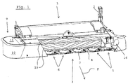
- a mower 1 for mowing agricultural stalk or sheet material is shown, which can be grown via a frame assembly 2, for example, to a Dreiticianhub Schau an agricultural traction and drive machine or the like.
- the mower 1 may be mounted on the frame assembly 2 on a chassis and thus be moved over the field or meadow surface to be processed.
- the mower When mowing the mower is run in the direction of travel and working F on the field or meadow area, with a part of the weight of the machine is supported on the ground, while the other part of the weight of the machine under a regulated soil pressure relief of the frame assembly 2 and the downstream machine components as three-point lift or chassis is added. How to continue Fig.
- the mower 1 comprises a Gurherbau group 3, which is composed of transverse to the travel and working direction F on a mower 4 mounted cutting members 5.
- the cutting elements 5 include ground-level rotary body 6, which have the shape of a mower disc 7 and are equipped on its outer periphery with two oppositely mounted cutting blades 8.
- the invention may also be based on a mower subassembly, in which the cutting elements are designed as so-called mowing drums, wherein the cutting elements are mounted on their side facing away from the earth on a drive spar of the frame assembly 2. From the Fig.
- the mower assembly 3 is surrounded by a protective and cover assembly 9, which is here essentially designed as a protective cloth assembly 10 and as a protective hood 11, wherein parts of, a processing device 12 with two superposed processing rollers 13 surrounding housing in the Protective cover 11 are integrated with.
- the rotationally driven processing rollers 13 of the processing device 12 pick up the stalk or sheet material cut by the cutting elements 5, squeeze it and place it then back on the field or meadow floor. By this measure, the drying process is significantly accelerated.
- FIG. 1 With regard to the mower assembly 3 surrounding protective and cover assembly 9 is from the illustration in Fig. 1 very clearly shows that the environment of the mower assembly 3 during the harvesting operation with respect to a discharge of unwanted air flows is a relatively close foreclosed area, so that without suitable technical aids a discharge of unwanted air currents is hardly possible.
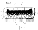
- Fig. 2 shows a schematic view of a mower assembly 3, in which above a cutter bar 4, the mowing device 7 designed as cutting members 5 are rotatably mounted.
- the mower plates 7 largely rotate in opposite directions of rotation, thereby generating air currents which are marked with flow indication arrows 15.
- two adjacent mower plates 7 move in the direction of travel and working direction F, an air flow is created which acts on the stalk or sheet material still to be mowed so that it is pressed over during mowing, so that thereby the unwanted streaking is caused.
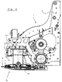
- Fig. 3 the mower 1 is illustrated in more detail in a partially broken representation, for reasons of improved clarity, the protective cloth assembly 10 and the protective cover 11 has been omitted. It can therefore be clearly seen that the mower subassembly 3 is assigned an active exhaust unit 16. By sucking a sufficiently large amount of air from the area located below the protective and cover assembly 9 surrounding area of the mower assembly 3 is ensured according to the invention that the unwanted, directed in the direction of still mowed or leaf material air flow (see arrow 15 in Fig. 2 ) is deflected in a direction in which it no longer acts on the stalk or Blattgut still to be mowed.
- the active suction unit 16 is designed as a fan or blower unit 17 with a radial flow direction and sucks on its side facing the ground from the sufficiently large amount of air and leads this subsequently in the area outside the protection and Cover assembly 9 from.
- the removal of the extracted from the surrounding area of the mower assembly 3 air quantity takes place here via an air duct 22 in an area behind the processing device 12, so that the extracted air quantity can serve here to support the storage of stalk or leaf material on the field or meadow area ,
- the mower assembly 3 may be provided to assign the mower assembly 3 also a plurality of fan or fan units 17.
- the mowing machine 1 is equipped with a fan or blower unit 17 on the left and right outer sides in the travel and working direction F.
- Fig. 4 is a detailed representation of the design and drive connection of a fan or blower unit 17 is illustrated in more detail.
- a conveyor and guide drum 18 to which at the top of a provided with conveying elements 19 fan or fan motor 20 connects, which within a fan or blower housing 21 rotatably driven is.
- fan or blower unit 17 is supplied with drive energy.
Landscapes
- Life Sciences & Earth Sciences (AREA)
- Environmental Sciences (AREA)
- Harvester Elements (AREA)
Priority Applications (1)
| Application Number | Priority Date | Filing Date | Title |
|---|---|---|---|
| PL16001065T PL3092885T3 (pl) | 2015-05-15 | 2016-05-11 | Kosiarka |
Applications Claiming Priority (1)
| Application Number | Priority Date | Filing Date | Title |
|---|---|---|---|
| DE102015006065.1A DE102015006065A1 (de) | 2015-05-15 | 2015-05-15 | Mähmaschine |
Publications (2)
| Publication Number | Publication Date |
|---|---|
| EP3092885A1 true EP3092885A1 (fr) | 2016-11-16 |
| EP3092885B1 EP3092885B1 (fr) | 2020-06-03 |
Family
ID=55966979
Family Applications (1)
| Application Number | Title | Priority Date | Filing Date |
|---|---|---|---|
| EP16001065.8A Not-in-force EP3092885B1 (fr) | 2015-05-15 | 2016-05-11 | Faucheuse |
Country Status (5)
| Country | Link |
|---|---|
| US (1) | US20160330905A1 (fr) |
| EP (1) | EP3092885B1 (fr) |
| DE (1) | DE102015006065A1 (fr) |
| DK (1) | DK3092885T3 (fr) |
| PL (1) | PL3092885T3 (fr) |
Families Citing this family (3)
| Publication number | Priority date | Publication date | Assignee | Title |
|---|---|---|---|---|
| EP3841862B1 (fr) * | 2019-12-23 | 2024-04-24 | MULAG FAHRZEUGWERK Heinz Wössner GmbH & CO. KG | Tête faucheuse rotative |
| US20240181502A1 (en) * | 2021-09-03 | 2024-06-06 | Lg Energy Solution, Ltd. | Foreign Matter Removal Device |
| CN121128429B (zh) * | 2025-09-30 | 2026-02-03 | 吉林省产品质量监督检验院(吉林省农产品认证中心) | 一种具有防堆积功能的智能化割草机 |
Citations (5)
| Publication number | Priority date | Publication date | Assignee | Title |
|---|---|---|---|---|
| WO1986003932A1 (fr) * | 1985-01-14 | 1986-07-17 | Glen Thomas Anthony Hewson | Moissonneuse agricole |
| EP0763319A1 (fr) * | 1995-09-18 | 1997-03-19 | Gianni Ferrari S.r.l. | Perfectionnements aux tondeuses à gazon |
| US5768865A (en) * | 1996-07-31 | 1998-06-23 | Deere & Company | Header equipped with rotary cutterbar and crop converging structure |
| DE20108505U1 (de) | 2001-05-19 | 2001-10-31 | Niemeyer Landmaschinen GmbH, 48477 Hörstel | Kreiselmäher mit verbesserten Mäheigenschaften |
| US20130111863A1 (en) * | 2011-11-07 | 2013-05-09 | Kondex Corporation | Disc Mower Blades |
-
2015
- 2015-05-15 DE DE102015006065.1A patent/DE102015006065A1/de not_active Ceased
-
2016
- 2016-05-11 PL PL16001065T patent/PL3092885T3/pl unknown
- 2016-05-11 US US15/151,514 patent/US20160330905A1/en not_active Abandoned
- 2016-05-11 EP EP16001065.8A patent/EP3092885B1/fr not_active Not-in-force
- 2016-05-11 DK DK16001065.8T patent/DK3092885T3/da active
Patent Citations (5)
| Publication number | Priority date | Publication date | Assignee | Title |
|---|---|---|---|---|
| WO1986003932A1 (fr) * | 1985-01-14 | 1986-07-17 | Glen Thomas Anthony Hewson | Moissonneuse agricole |
| EP0763319A1 (fr) * | 1995-09-18 | 1997-03-19 | Gianni Ferrari S.r.l. | Perfectionnements aux tondeuses à gazon |
| US5768865A (en) * | 1996-07-31 | 1998-06-23 | Deere & Company | Header equipped with rotary cutterbar and crop converging structure |
| DE20108505U1 (de) | 2001-05-19 | 2001-10-31 | Niemeyer Landmaschinen GmbH, 48477 Hörstel | Kreiselmäher mit verbesserten Mäheigenschaften |
| US20130111863A1 (en) * | 2011-11-07 | 2013-05-09 | Kondex Corporation | Disc Mower Blades |
Also Published As
| Publication number | Publication date |
|---|---|
| DE102015006065A1 (de) | 2016-11-17 |
| PL3092885T3 (pl) | 2020-11-16 |
| US20160330905A1 (en) | 2016-11-17 |
| DK3092885T3 (da) | 2020-08-17 |
| EP3092885B1 (fr) | 2020-06-03 |
Similar Documents
| Publication | Publication Date | Title |
|---|---|---|
| EP0985439B1 (fr) | Dispositif de nettoyage pour un filtre rotatif d'air de refroidissement | |
| DE69602900T2 (de) | Verbesserungen an Rasenmäher | |
| DE2912466C2 (de) | Schnittgutfördereinrichtung für Sichelrasenmäher | |
| DE102007009587A1 (de) | Vorrichtung zur Einstellung der Position des Nachbeschleunigungsorgans in einer landwirtschaftlichen Erntemaschine | |
| EP2255610A1 (fr) | Tête pour récolter des plantes en forme de tige | |
| CH641928A5 (de) | Futtererntemaschine. | |
| DE1632810C3 (de) | Mähmaschine | |
| EP3092885A1 (fr) | Faucheuse | |
| DE2528332A1 (de) | Grasauswurfvorrichtung an motorisch angetriebenen rasenmaehern | |
| DE102010028599A1 (de) | Erntegutrestehäcksel- und -verteilanordnung für einen Mähdrescher | |
| EP0818136B1 (fr) | Dispositif pour hacher des végétaux | |
| DE102017201160A1 (de) | Häckseltrommel für einen Feldhäcksler | |
| DE102013014692A1 (de) | Rasenpflegevorrichtung | |
| EP4054312B1 (fr) | Agencement d'équipement, véhicule de travail et procédé en particulier pour maintenir des zones vertes, fauchage, travail du sol, ou récolte de cultures brutes ou céréalières | |
| EP3697196B1 (fr) | Élément de coupe doté d'une coupe tractée | |
| AT511146B1 (de) | Erntevorrichtung | |
| DE2639519C3 (de) | Saugmähgerät | |
| DE2320126C2 (de) | Feldhäcksler | |
| EP3841862B1 (fr) | Tête faucheuse rotative | |
| DE102015118370A1 (de) | Vorrichtung zum Mähen, Vertikutieren und/oder Aufsammeln | |
| DE8224900U1 (de) | Vertikutiergeraet fuer die bodenbearbeitung von rasenflaechen | |
| AT263437B (de) | Blattabführvorrichtung für einen Köpfer an Rübenerntemaschinen | |
| DE20109416U1 (de) | Vorrichtung für land- und/oder gartenwirtschaftliche Zwecke | |
| DE69218887T2 (de) | Mähmaschine mit einem Rotor, welcher das geschnittene Gut insbesondere zu den Trägern der Schneidorgane bringt | |
| DE202024106560U1 (de) | Rasenmäher |
Legal Events
| Date | Code | Title | Description |
|---|---|---|---|
| PUAI | Public reference made under article 153(3) epc to a published international application that has entered the european phase |
Free format text: ORIGINAL CODE: 0009012 |
|
| AK | Designated contracting states |
Kind code of ref document: A1 Designated state(s): AL AT BE BG CH CY CZ DE DK EE ES FI FR GB GR HR HU IE IS IT LI LT LU LV MC MK MT NL NO PL PT RO RS SE SI SK SM TR |
|
| AX | Request for extension of the european patent |
Extension state: BA ME |
|
| STAA | Information on the status of an ep patent application or granted ep patent |
Free format text: STATUS: REQUEST FOR EXAMINATION WAS MADE |
|
| 17P | Request for examination filed |
Effective date: 20170505 |
|
| RBV | Designated contracting states (corrected) |
Designated state(s): AL AT BE BG CH CY CZ DE DK EE ES FI FR GB GR HR HU IE IS IT LI LT LU LV MC MK MT NL NO PL PT RO RS SE SI SK SM TR |
|
| STAA | Information on the status of an ep patent application or granted ep patent |
Free format text: STATUS: EXAMINATION IS IN PROGRESS |
|
| 17Q | First examination report despatched |
Effective date: 20190523 |
|
| GRAP | Despatch of communication of intention to grant a patent |
Free format text: ORIGINAL CODE: EPIDOSNIGR1 |
|
| STAA | Information on the status of an ep patent application or granted ep patent |
Free format text: STATUS: GRANT OF PATENT IS INTENDED |
|
| INTG | Intention to grant announced |
Effective date: 20200207 |
|
| GRAS | Grant fee paid |
Free format text: ORIGINAL CODE: EPIDOSNIGR3 |
|
| GRAA | (expected) grant |
Free format text: ORIGINAL CODE: 0009210 |
|
| STAA | Information on the status of an ep patent application or granted ep patent |
Free format text: STATUS: THE PATENT HAS BEEN GRANTED |
|
| AK | Designated contracting states |
Kind code of ref document: B1 Designated state(s): AL AT BE BG CH CY CZ DE DK EE ES FI FR GB GR HR HU IE IS IT LI LT LU LV MC MK MT NL NO PL PT RO RS SE SI SK SM TR |
|
| REG | Reference to a national code |
Ref country code: GB Ref legal event code: FG4D Free format text: NOT ENGLISH |
|
| REG | Reference to a national code |
Ref country code: CH Ref legal event code: EP Ref country code: AT Ref legal event code: REF Ref document number: 1275999 Country of ref document: AT Kind code of ref document: T Effective date: 20200615 |
|
| REG | Reference to a national code |
Ref country code: DE Ref legal event code: R096 Ref document number: 502016010092 Country of ref document: DE |
|
| REG | Reference to a national code |
Ref country code: DK Ref legal event code: T3 Effective date: 20200810 |
|
| REG | Reference to a national code |
Ref country code: LT Ref legal event code: MG4D |
|
| PG25 | Lapsed in a contracting state [announced via postgrant information from national office to epo] |
Ref country code: FI Free format text: LAPSE BECAUSE OF FAILURE TO SUBMIT A TRANSLATION OF THE DESCRIPTION OR TO PAY THE FEE WITHIN THE PRESCRIBED TIME-LIMIT Effective date: 20200603 Ref country code: SE Free format text: LAPSE BECAUSE OF FAILURE TO SUBMIT A TRANSLATION OF THE DESCRIPTION OR TO PAY THE FEE WITHIN THE PRESCRIBED TIME-LIMIT Effective date: 20200603 Ref country code: LT Free format text: LAPSE BECAUSE OF FAILURE TO SUBMIT A TRANSLATION OF THE DESCRIPTION OR TO PAY THE FEE WITHIN THE PRESCRIBED TIME-LIMIT Effective date: 20200603 Ref country code: NO Free format text: LAPSE BECAUSE OF FAILURE TO SUBMIT A TRANSLATION OF THE DESCRIPTION OR TO PAY THE FEE WITHIN THE PRESCRIBED TIME-LIMIT Effective date: 20200903 Ref country code: GR Free format text: LAPSE BECAUSE OF FAILURE TO SUBMIT A TRANSLATION OF THE DESCRIPTION OR TO PAY THE FEE WITHIN THE PRESCRIBED TIME-LIMIT Effective date: 20200904 |
|
| REG | Reference to a national code |
Ref country code: NL Ref legal event code: MP Effective date: 20200603 |
|
| PG25 | Lapsed in a contracting state [announced via postgrant information from national office to epo] |
Ref country code: BG Free format text: LAPSE BECAUSE OF FAILURE TO SUBMIT A TRANSLATION OF THE DESCRIPTION OR TO PAY THE FEE WITHIN THE PRESCRIBED TIME-LIMIT Effective date: 20200903 Ref country code: RS Free format text: LAPSE BECAUSE OF FAILURE TO SUBMIT A TRANSLATION OF THE DESCRIPTION OR TO PAY THE FEE WITHIN THE PRESCRIBED TIME-LIMIT Effective date: 20200603 Ref country code: LV Free format text: LAPSE BECAUSE OF FAILURE TO SUBMIT A TRANSLATION OF THE DESCRIPTION OR TO PAY THE FEE WITHIN THE PRESCRIBED TIME-LIMIT Effective date: 20200603 Ref country code: HR Free format text: LAPSE BECAUSE OF FAILURE TO SUBMIT A TRANSLATION OF THE DESCRIPTION OR TO PAY THE FEE WITHIN THE PRESCRIBED TIME-LIMIT Effective date: 20200603 |
|
| PG25 | Lapsed in a contracting state [announced via postgrant information from national office to epo] |
Ref country code: AL Free format text: LAPSE BECAUSE OF FAILURE TO SUBMIT A TRANSLATION OF THE DESCRIPTION OR TO PAY THE FEE WITHIN THE PRESCRIBED TIME-LIMIT Effective date: 20200603 Ref country code: NL Free format text: LAPSE BECAUSE OF FAILURE TO SUBMIT A TRANSLATION OF THE DESCRIPTION OR TO PAY THE FEE WITHIN THE PRESCRIBED TIME-LIMIT Effective date: 20200603 |
|
| PG25 | Lapsed in a contracting state [announced via postgrant information from national office to epo] |
Ref country code: ES Free format text: LAPSE BECAUSE OF FAILURE TO SUBMIT A TRANSLATION OF THE DESCRIPTION OR TO PAY THE FEE WITHIN THE PRESCRIBED TIME-LIMIT Effective date: 20200603 Ref country code: SM Free format text: LAPSE BECAUSE OF FAILURE TO SUBMIT A TRANSLATION OF THE DESCRIPTION OR TO PAY THE FEE WITHIN THE PRESCRIBED TIME-LIMIT Effective date: 20200603 Ref country code: EE Free format text: LAPSE BECAUSE OF FAILURE TO SUBMIT A TRANSLATION OF THE DESCRIPTION OR TO PAY THE FEE WITHIN THE PRESCRIBED TIME-LIMIT Effective date: 20200603 Ref country code: CZ Free format text: LAPSE BECAUSE OF FAILURE TO SUBMIT A TRANSLATION OF THE DESCRIPTION OR TO PAY THE FEE WITHIN THE PRESCRIBED TIME-LIMIT Effective date: 20200603 Ref country code: RO Free format text: LAPSE BECAUSE OF FAILURE TO SUBMIT A TRANSLATION OF THE DESCRIPTION OR TO PAY THE FEE WITHIN THE PRESCRIBED TIME-LIMIT Effective date: 20200603 Ref country code: PT Free format text: LAPSE BECAUSE OF FAILURE TO SUBMIT A TRANSLATION OF THE DESCRIPTION OR TO PAY THE FEE WITHIN THE PRESCRIBED TIME-LIMIT Effective date: 20201006 Ref country code: IT Free format text: LAPSE BECAUSE OF FAILURE TO SUBMIT A TRANSLATION OF THE DESCRIPTION OR TO PAY THE FEE WITHIN THE PRESCRIBED TIME-LIMIT Effective date: 20200603 |
|
| PG25 | Lapsed in a contracting state [announced via postgrant information from national office to epo] |
Ref country code: SK Free format text: LAPSE BECAUSE OF FAILURE TO SUBMIT A TRANSLATION OF THE DESCRIPTION OR TO PAY THE FEE WITHIN THE PRESCRIBED TIME-LIMIT Effective date: 20200603 Ref country code: IS Free format text: LAPSE BECAUSE OF FAILURE TO SUBMIT A TRANSLATION OF THE DESCRIPTION OR TO PAY THE FEE WITHIN THE PRESCRIBED TIME-LIMIT Effective date: 20201003 |
|
| REG | Reference to a national code |
Ref country code: DE Ref legal event code: R097 Ref document number: 502016010092 Country of ref document: DE |
|
| PLBE | No opposition filed within time limit |
Free format text: ORIGINAL CODE: 0009261 |
|
| STAA | Information on the status of an ep patent application or granted ep patent |
Free format text: STATUS: NO OPPOSITION FILED WITHIN TIME LIMIT |
|
| 26N | No opposition filed |
Effective date: 20210304 |
|
| PG25 | Lapsed in a contracting state [announced via postgrant information from national office to epo] |
Ref country code: SI Free format text: LAPSE BECAUSE OF FAILURE TO SUBMIT A TRANSLATION OF THE DESCRIPTION OR TO PAY THE FEE WITHIN THE PRESCRIBED TIME-LIMIT Effective date: 20200603 |
|
| REG | Reference to a national code |
Ref country code: CH Ref legal event code: PL |
|
| GBPC | Gb: european patent ceased through non-payment of renewal fee |
Effective date: 20210511 |
|
| PG25 | Lapsed in a contracting state [announced via postgrant information from national office to epo] |
Ref country code: CH Free format text: LAPSE BECAUSE OF NON-PAYMENT OF DUE FEES Effective date: 20210531 Ref country code: LU Free format text: LAPSE BECAUSE OF NON-PAYMENT OF DUE FEES Effective date: 20210511 Ref country code: MC Free format text: LAPSE BECAUSE OF FAILURE TO SUBMIT A TRANSLATION OF THE DESCRIPTION OR TO PAY THE FEE WITHIN THE PRESCRIBED TIME-LIMIT Effective date: 20200603 Ref country code: LI Free format text: LAPSE BECAUSE OF NON-PAYMENT OF DUE FEES Effective date: 20210531 |
|
| REG | Reference to a national code |
Ref country code: BE Ref legal event code: MM Effective date: 20210531 |
|
| PG25 | Lapsed in a contracting state [announced via postgrant information from national office to epo] |
Ref country code: GB Free format text: LAPSE BECAUSE OF NON-PAYMENT OF DUE FEES Effective date: 20210511 |
|
| PG25 | Lapsed in a contracting state [announced via postgrant information from national office to epo] |
Ref country code: BE Free format text: LAPSE BECAUSE OF NON-PAYMENT OF DUE FEES Effective date: 20210531 |
|
| PGFP | Annual fee paid to national office [announced via postgrant information from national office to epo] |
Ref country code: IE Payment date: 20220517 Year of fee payment: 7 Ref country code: FR Payment date: 20220523 Year of fee payment: 7 Ref country code: DK Payment date: 20220523 Year of fee payment: 7 Ref country code: DE Payment date: 20220519 Year of fee payment: 7 |
|
| PGFP | Annual fee paid to national office [announced via postgrant information from national office to epo] |
Ref country code: AT Payment date: 20220517 Year of fee payment: 7 |
|
| PG25 | Lapsed in a contracting state [announced via postgrant information from national office to epo] |
Ref country code: HU Free format text: LAPSE BECAUSE OF FAILURE TO SUBMIT A TRANSLATION OF THE DESCRIPTION OR TO PAY THE FEE WITHIN THE PRESCRIBED TIME-LIMIT; INVALID AB INITIO Effective date: 20160511 |
|
| PG25 | Lapsed in a contracting state [announced via postgrant information from national office to epo] |
Ref country code: CY Free format text: LAPSE BECAUSE OF FAILURE TO SUBMIT A TRANSLATION OF THE DESCRIPTION OR TO PAY THE FEE WITHIN THE PRESCRIBED TIME-LIMIT Effective date: 20200603 |
|
| PGFP | Annual fee paid to national office [announced via postgrant information from national office to epo] |
Ref country code: PL Payment date: 20230508 Year of fee payment: 8 |
|
| REG | Reference to a national code |
Ref country code: DE Ref legal event code: R119 Ref document number: 502016010092 Country of ref document: DE |
|
| REG | Reference to a national code |
Ref country code: DK Ref legal event code: EBP Effective date: 20230531 |
|
| REG | Reference to a national code |
Ref country code: AT Ref legal event code: MM01 Ref document number: 1275999 Country of ref document: AT Kind code of ref document: T Effective date: 20230511 |
|
| PG25 | Lapsed in a contracting state [announced via postgrant information from national office to epo] |
Ref country code: AT Free format text: LAPSE BECAUSE OF NON-PAYMENT OF DUE FEES Effective date: 20230511 |
|
| REG | Reference to a national code |
Ref country code: IE Ref legal event code: MM4A |
|
| PG25 | Lapsed in a contracting state [announced via postgrant information from national office to epo] |
Ref country code: IE Free format text: LAPSE BECAUSE OF NON-PAYMENT OF DUE FEES Effective date: 20230511 |
|
| PG25 | Lapsed in a contracting state [announced via postgrant information from national office to epo] |
Ref country code: MK Free format text: LAPSE BECAUSE OF FAILURE TO SUBMIT A TRANSLATION OF THE DESCRIPTION OR TO PAY THE FEE WITHIN THE PRESCRIBED TIME-LIMIT Effective date: 20200603 Ref country code: IE Free format text: LAPSE BECAUSE OF NON-PAYMENT OF DUE FEES Effective date: 20230511 Ref country code: DK Free format text: LAPSE BECAUSE OF NON-PAYMENT OF DUE FEES Effective date: 20230531 Ref country code: DE Free format text: LAPSE BECAUSE OF NON-PAYMENT OF DUE FEES Effective date: 20231201 |
|
| PG25 | Lapsed in a contracting state [announced via postgrant information from national office to epo] |
Ref country code: FR Free format text: LAPSE BECAUSE OF NON-PAYMENT OF DUE FEES Effective date: 20230531 |
|
| PG25 | Lapsed in a contracting state [announced via postgrant information from national office to epo] |
Ref country code: TR Free format text: LAPSE BECAUSE OF FAILURE TO SUBMIT A TRANSLATION OF THE DESCRIPTION OR TO PAY THE FEE WITHIN THE PRESCRIBED TIME-LIMIT Effective date: 20200603 |
|
| PG25 | Lapsed in a contracting state [announced via postgrant information from national office to epo] |
Ref country code: MT Free format text: LAPSE BECAUSE OF FAILURE TO SUBMIT A TRANSLATION OF THE DESCRIPTION OR TO PAY THE FEE WITHIN THE PRESCRIBED TIME-LIMIT Effective date: 20200603 |
|
| PG25 | Lapsed in a contracting state [announced via postgrant information from national office to epo] |
Ref country code: PL Free format text: LAPSE BECAUSE OF NON-PAYMENT OF DUE FEES Effective date: 20240511 |