EP3092961B1 - Externer befestigungsrahmen für knochentransport - Google Patents
Externer befestigungsrahmen für knochentransport Download PDFInfo
- Publication number
- EP3092961B1 EP3092961B1 EP16170790.6A EP16170790A EP3092961B1 EP 3092961 B1 EP3092961 B1 EP 3092961B1 EP 16170790 A EP16170790 A EP 16170790A EP 3092961 B1 EP3092961 B1 EP 3092961B1
- Authority
- EP
- European Patent Office
- Prior art keywords
- ring
- bone
- transport frame
- frame according
- strut
- Prior art date
- Legal status (The legal status is an assumption and is not a legal conclusion. Google has not performed a legal analysis and makes no representation as to the accuracy of the status listed.)
- Active
Links
Images












Classifications
-
- A—HUMAN NECESSITIES
- A61—MEDICAL OR VETERINARY SCIENCE; HYGIENE
- A61B—DIAGNOSIS; SURGERY; IDENTIFICATION
- A61B17/00—Surgical instruments, devices or methods
- A61B17/56—Surgical instruments or methods for treatment of bones or joints; Devices specially adapted therefor
- A61B17/58—Surgical instruments or methods for treatment of bones or joints; Devices specially adapted therefor for osteosynthesis, e.g. bone plates, screws or setting implements
- A61B17/60—Surgical instruments or methods for treatment of bones or joints; Devices specially adapted therefor for osteosynthesis, e.g. bone plates, screws or setting implements for external osteosynthesis, e.g. distractors, contractors
- A61B17/62—Ring frames, i.e. devices extending around the bones to be positioned
-
- A—HUMAN NECESSITIES
- A61—MEDICAL OR VETERINARY SCIENCE; HYGIENE
- A61B—DIAGNOSIS; SURGERY; IDENTIFICATION
- A61B17/00—Surgical instruments, devices or methods
- A61B17/56—Surgical instruments or methods for treatment of bones or joints; Devices specially adapted therefor
- A61B17/58—Surgical instruments or methods for treatment of bones or joints; Devices specially adapted therefor for osteosynthesis, e.g. bone plates, screws or setting implements
- A61B17/60—Surgical instruments or methods for treatment of bones or joints; Devices specially adapted therefor for osteosynthesis, e.g. bone plates, screws or setting implements for external osteosynthesis, e.g. distractors, contractors
- A61B17/66—Alignment, compression or distraction mechanisms
Definitions
- the present invention relates to systems for manipulating the orientation of a plurality of bone fragments with respect to one another, and in particular it relates to external fixation devices in which rings thereof may be manipulated with respect to one another via bone transport assemblies.
- External fixation frames may be used to correct skeletal deformities using the distraction osteogenesis process.
- the Ilizarov external fixation devices for example, are widely used for this purpose.
- the Ilizarov-type devices may be used to translate bone segments by manipulating rings connected to each bone segment.
- External fixation devices generally utilize a plurality of threaded rods fixated to through-holes in the rings to build the frame. In order to build a desired frame, these rods generally have to have different lengths. A problem that may arise out of this is that such external fixation frames generally do not allow significant manipulation of what may be referred to as a transport ring without disassembling and then reassembling the frame or adding new devices. These systems generally require removal of the entire frame in order to perform reconstruction.
- the patient or surgeon generally moves the rings or percutaneous fixation components manually or mechanically by adjusting a series of adjustment mechanism, such as nuts, for example.
- a traditional method of adjusting the frame height generally requires the surgeon to loosen an individual nut gradually while tightening another other nut in order to secure the frame. These position adjustments must be done where the nuts are secured, making it very difficult for the patient to make the required daily adjustments with consideration of stable fixation in mind.
- Other devices use different techniques to adjust the effective length of the rods, but all must be adjusted somewhere between the ends, offering limited access for the patient.
- WO 2010/104567 discloses an external fixation system comprising: first and second planar at least part-circular ring elements, the first ring element having a circumferential track extending along the part-circular circumference thereof; a plurality of struts each having a first and second ends, the first end of each strut coupled to the first ring by a first connector and the second end of each strut coupled to a second ring by a second connector, the first connector including a spherical joint; the second connector non-rotatably coupled to the second ring, the strut second end being coupled to the second connector by a U-joint, and shuttles mounted on the track of the first ring for movement there along with one shuttle coupled to each strut.
- a bone transport frame is provided with the features according to claim 1.
- proximal and distal correspond, respectively, to that end of the bone transport frame nearest the patient's heart and the end of the bone transport frame farthest from the patient's heart.
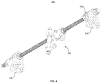
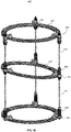
- the bone transport frame 100 generally comprises a plurality of bone transport assemblies 150, a plurality of bone transport rings 200, a plurality of strut assemblies 300, a plurality of top click mechanisms 400, and a plurality of devices that interact with different segments or portions of a bone.
- Each of the bone transport rings 200 has a lower ring surface 280 and an upper ring surface 285 as well as an outer ring surface 290 and an inner ring surface 295.
- Upper 285, lower 280, inner 295, and outer 290 ring surfaces are substantially flat such that each ring has a vertical cross section that is substantially rectangular.
- ring surfaces 280, 285, 290 and 295 need not be flat, but rather can take on various shapes to accommodate other devices such as clamps, for example.
- each of the bone transport rings 200 resides a plurality of through-holes 210 that extend through both the upper 285 and lower 280 ring surfaces.
- the through-holes 210 facilitate mechanical connections between the strut assemblies 300 and numerous other devices the surgeon may deem necessary during use of bone transport frame 100.
- Such devices include bone-pin retaining devices 920 and bone-wire retaining devices 960. Due to the substantially flat contours of the ring surfaces and the plurality of through-holes 210, a user is provided significant flexibility in appropriately placing the bone-pin retaining devices 920 and bone-wire retaining devices 960 at desired locations. Thus, a user can couple any of these devices at numerous locations around the circumference of each of the bone transport rings 200 as well as coupling the devices at the upper 285 or lower 280 ring surfaces of the bone transport rings 200. Devices that can be used to facilitate interaction between the bone transport frame 100 and portions of a bone include, for example, a series of bone-wires 980 and bone-pins 940.
- bone transport frame 100 includes a proximal ring 220, a medial ring 240, and a distal ring 260 wherein the proximal ring 220 is affixed to a first bone segment 820, the medial ring 240 is affixed to a second bone segment 840, and the distal ring 260 is affixed to a third bone segment 860.
- the first bone segment 820 and second bone segment 840 are typically separated by an osteotomy created in the bone to allow for osteogenesis as the second bone segment is incrementally transported toward the third bone segment 840.
- the second bone segment 820 and third bone segment 860 are typically separated by a deformity, such as a fracture or the like.
- Strut assemblies 300 act to stabilize the bone segments and to provide for transportation thereof.
- FIGS. 1-3 show bone transport frame 100 including three strut assemblies 300, but in other examples more than three strut assemblies 300 may be utilized, such as four, five, six or more strut assemblies 300, for example.
- each strut assembly 300 includes a top click mechanism 400.
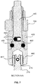
- the top-click mechanism 400 includes a square head 410, a clamping nut 420, a clicking body 430, a driver body 440, a spring and ball system 460, and a series of retaining balls 450.
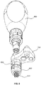
- the square head 410 provides an interface to mate with a screw driver 480 as shown in FIG. 6 .
- the clamping nut 420 clamps a flange 700 to the top-click mechanism 400.
- the driver body 440 is rigidly coupled to the strut 310 via a coupling member 415 and pin 417 so that rotation of the driver body 440 causes the strut 310 to rotate in unison with the driver body 440. Further, the driver body 440 has an elongated portion 445 which terminates at the proximal end thereof as at square head 410.
- a clicking body 430 fits over the elongated portion 445 of the driver body 440 like a sleeve, for example.
- the clicking body 430 is axially retained by a series of retaining balls 450 that allow the clicking body 430 to rotate with respect to the driver body 440 without translating with respect to the driver body.
- a cylindrical notch 470 is formed within the elongated portion of the driver body 440.
- a detent means in the form of a spring and ball system 460, for example, which communicates with a series of recesses 490 on the internal portion of the clicking body 430 as shown in FIG. 8 .
- the recesses or profile cuts 490 are created so that a portion of the ball of the spring and ball system 460 sits in and partially conforms to each of the profile cuts 490. Further, the profile cuts 490 are such that as the driver body 440 is rotated, the ball of the ball and spring system 460 is capable of translating to an adjacent profile cut 490 creating a clicking sound and feel.
- Each profile cut 490 should be spaced and each strut 310 should be threaded so that each click corresponds with the strut 310 rotating a sufficient amount to cause the medial ring 240 to axially translate along the strut 310 a clinically optimal length.
- the clinically optimal length is approximately 0.25mm.
- the rate of osteogenesis between the first bone segment 820 and second bone segment 840 will be approximately 1 mm per day.
- a single "click" can correspond to different distances lengths, depending on the specific needs for a particular situation.
- the ball and spring system 460 additionally functions to constrain the driver body 440 and strut 310 from the rotation provided by the retaining balls 450.
- the driver body 440 and strut 310 cannot rotate until a screw driver 480 applies the proper torque to the square nut 410 to overcome the force of the spring and ball system 460 and translate the ball to the adjacent profile cut 490.
- An arrow 495 as shown in FIG. 8 that points distally is etched on the outer surface of the clicking body 430 and is lined up with a corresponding number 485 etched on the outer surface of the driver body 440.
- the numbers 485 are spaced such that each click corresponds to a rotation of the arrow 495 from a first number 485 to an adjacent number 485.
- the numbers 485 are placed on the flat surfaces of an octagon and numbered 1-4 and 4-1. This numbering is done so that the patient can keep track of the preferred four adjustments per day, for example.
- Such a clicking mechanism is disclosed in U.S. Patent Application Publication No. 2012/0041439 .
- a flange 700 extends from the outer surface of a portion of the clicking body 430 and is clamped against the clicking body 430 by a clamping nut 420.
- clamping the flange 700 will not only secure the flange to the clicking body 430 but also prohibits the clicking body 430 from rotating with the driver body 440 and strut 310.
- the flange 700 includes anterior through-holes 740 and a medial through-hole 760 in a triangular pattern.
- the anterior through-holes 740 are the primary junctions for coupling the flange 700 to the bone transport rings 200.
- a single retaining pin 720 can be used to couple the flange 700 to the through-holes 210 of the transport rings 200.
- both anterior through-holes 740 can be used, each in conjunction with a retaining pin 720, to provide an anti-torque function that prevents rotation of the flange 700 with respect to the transport ring 200.
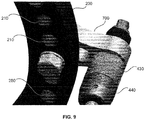
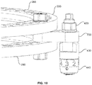
- Other connection mechanisms besides retaining pints 720 can be used. For example, a user may choose to use a bolt and nut system in lieu of the retaining pin to secure the flange to the transport ring as seen in FIGS. 9-10 .
- the flat surfaces of the flange 700 and the transport rings 200 allow the flange 700 to be coupled to the upper 285 or lower 280 ring surfaces of the transport rings 200 as seen in FIG. 10 .
- This provides the user with the option of coupling a bone transport ring 200 to the top of flange 700 or to the bottom of flange 700.
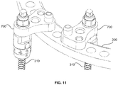
- the dimensions of the flange 700 allow the strut assembly 300 to be coupled to the bone transport ring 200 such that the strut 310 can lie either inside the bone transport ring 200 or outside of the bone transport ring 200 as seen in FIG. 11 .
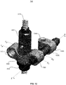
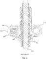
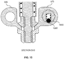
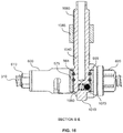
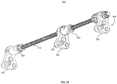
- FIGS. 12-16 there are shown different illustrations of a bone transport assembly 150.
- the bone transport assembly generally includes a ball and socket joint 500, a quick release mechanism 600, and a translational rod 1000.
- the ball and socket joint 500 has a hyperbolic collar 595 that fits loosely over the distal end of the quick release mechanism 600 and is coupled to the quick release mechanism 600 by a locking nut 620 that substantially conforms to the shape of the hyperbolic collar 595.
- the locking nut 620 is loosened, the ball and socket joint 500 is free to swivel about a three dimensional axis until the locking nut 620 is tightened, thereby locking the ball and socket joint 500 at its latest position.
- This feature enables the medial ring 240 to rotate so that it is no longer parallel with the proximal 220 and distal 260 rings, thus allowing the second bone segment 840 to be more precisely aligned with the third bone segment 860 as the distraction osteogenesis process progresses.
- FIG. 3 An example of a medial ring 240 being non-parallel to a proximal 220 and distal 260 ring is shown in FIG. 3 , for example.
- the ball and socket joint 500 also helps in aligning second bone segment 840 with third bone segment 860 during the docking process. A user can accomplish this by unlocking locking nut 620, marginally loosening the ball and socket joint 500, and rotating at least one of the top click mechanism 400 and translational short rod 1000 or translation bolt 730.
- the hyperbolic collar 595 terminates on two sides with a first retaining ring 575 on one side and a second retaining ring 585 on the opposing side.
- the first retaining ring 575 connects and retains the translational rod 1000 to the ball and socket joint 500 by way of a series of retaining pins 565.
- the second retaining ring 585 provides the user the option to add an extra rod of any type, for example, to provide extra stiffness to the frame 100, if desired.
- the translational rod 1000 has a structure similar to the click mechanism 400. One end of the translational rod 1000 terminates in a square head 1010 that can mate with a driving tool such as a screw driver.
- the translational rod 1000 includes a driving body 1040 with a cylindrical notch 1070 that houses a spring and ball system 1060.
- a first retaining ring 575 includes recesses or profile cuts 1090. As the driving body 1040 is rotated, the ball of the spring and ball system 1060 may move from one profile cut 1090 and into an adjacent profile cut 1090.
- the driving body 1040 is threadedly mated to a connector piece 1085.
- the connector piece 1085 includes an aperture 1095.
- the connector piece 1085 can be fixed to a bone transport ring 200 by means of a fastener, such as a locking nut 1097 that extends through a through-hole 210 of a bone transport ring 200 and further through the aperture 1095 of the connector piece 1085.
- the driving body 1040 rotates.
- the spring and ball system 1060 provides feedback to the user each time the ball moves into one of the profile cuts 1090 of the first retaining ring 575.
- the rotation of the driver body 1040 forces the outer body 1080 to move axially.
- the axial movement of the outer body 1080 is caused by the inability of the outer body 1080 to rotate, due to the rigid connection to the connecting piece 1085 and the bone ring 200.
- the axial movement of the outer body 1080 causes the connector piece 1085 to move in conjunction with the outer body 1080.
- the movement of the connector piece 1085 moves the bone transport ring 200 to which the connector piece 1085 is attached, allowing translation of the bone transport ring 200 towards or away from strut assembly 300.
- This translation of the medial ring 240 may be useful when "docking" the bone.
- the docking phase is reached at the end of the transport phase, when the second bone segment 840 reaches the third bone segment 860. Sometimes the two bone segments do not align well and then it becomes advantageous to translate the medial ring 240 to correct the alignment between the second bone segment 840 and the third bone segment 860.
- Quick release mechanism 600 of bone transport assembly 150 allows for quick adjustment of the medial ring 240 compared to the finer adjustment by the top click mechanism 400. It should be noted that the quick release mechanism 600 is only intended to be used prior to fixation of the bone transport frame 100 to the patient. Because the distal ring 260 includes an anti-torque quick release mechanism 605, which is substantially similar to the quick release mechanism 600, the workings of the quick release mechanism 600 are omitted here and are described with reference to the anti-torque quick release mechanism 605.
- the distal portion of the strut assembly 300 generally includes a flange 700, an anti-torque quick release mechanism 605, and a tapered nut 630.
- the anti-torque quick release mechanism 605 has an unlocked state, a semi-locked state, and a locked state. In the unlocked state, the anti-torque quick release mechanism 605, flange 700 and attached distal ring 260 are free to move vertically up or down the strut 310 regardless of rotation of the strut 310. This allows for quick adjustment of the distal ring 260 prior to fixing the bone transport frame 100 to the patient's bone.
- the quick release mechanism 600 provided with the medial ring 240 has the same feature.
- the anti-torque quick release mechanism 605 travels vertically up or down the strut 310 with rotation of the strut 310 by the top click mechanism 400.
- the user rotates the anti-torque quick release mechanism 605.
- the body of the anti-torque quick release mechanism 605 is pushed proximally, compressing spring 670.
- This moves locking pin 680 into a position in groove 690 which allows for rotation of the body of the anti-torque quick release mechanism 605. Rotation is continued until the locking pin 680 traverses to the opposite side of the groove, allowing the spring to decompress.
- the bearings 660 engage the thread of the strut 310, disabling the anti-torque quick release mechanism 605 from freely travelling vertically up or down the strut 310. Rather, it will move vertically up or down the strut 310 only with rotation of the strut 310 by virtue of rotation of the top click mechanism 400. It should be noted, however, that this function is only desirable for the quick release mechanism 600 coupled to the bone transport assembly 150, and not for the anti-torque quick release mechanism 605.
- the anti-torque quick release mechanism 605 should only be configured in the unlocked state or the locked state, and not the semi-locked state.
- the tapered nut 630 is threaded onto sleeve 640. Because of the taper inside tapered nut 630, the collet 635 at the tip of sleeve 640 bends inward and creates friction with the strut 310 when the tapered nut 630 is tightened. This friction causes the tapered nut 630, sleeve 640 and strut 310 to move as a single unit, rotating together with the strut 310. This rotation is possible because of the retaining balls 650, which allow these pieces to rotate inside the flange 700.
- the flange 700 is connected to the distal ring 260. Because there is no thread at the interface between the flange 700 and the combination tapered nut 630, sleeve 640 and strut 310, the distal ring 260 is not driven vertically up or down the strut 310 when it is rotated by actuation of the top click mechanism 400.
- the quick release mechanism 600 has no anti-torque feature and thus can only be in the unlocked or semi-locked state. When the quick release mechanism 600 is in the semi-locked state, the medial ring 240 thus can be driven vertically up or down the strut 310 allowing for transport.
- the bearings 660 in addition to enabling the switch from the unlocked to the semi-locked positions, take much of the axial load when that load moves from the strut 310 to the sleeve 640 (e.g. when the patient is standing).
- the bent collet 635 alone may not be able to take all that axial loading.
- a screw 695 is provided at the far distal end of the strut 310 to prevent the anti-torque quick release mechanism 605 from sliding off the strut 310 when it is in the unlocked state and the distal ring 260 is being adjusted.
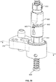
- the bone transport frame 100' generally includes a plurality of bone transport assemblies 150', a plurality of bone transport rings 200 and a plurality of strut assemblies 300.
- the bone transport assembly 150' coupled to the medial ring 240 includes a different structure such that the gradual translation of the medial ring 240 does not occur by way of a clicking mechanism.
- the second example of the bone transport assembly 150' comprises a quick release mechanism 600, a ball jointed flange 705, a series of hinge pin and bracket assemblies, a series of nuts, and a translational bolt.
- the ball jointed flange 705 has a hyperbolic collar 595 much like the hyperbolic collar 595 seen on the ball joint 500 of the first example.
- This ball jointed flange 705 is also coupled to the quick release mechanism 600 by means of the same locking nut 620.
- the hyperbolic collar 595 terminates with a flange like that disclosed elsewhere herein.
- a hinge pin 715 is coupled to the ball jointed flange 705 through the medial through-hole 760 and is axially retained by a series of nuts 725, but is capable of rotation within the medial through-hole 760.
- the hinge pin 715 terminates at the proximal end with a bracket 710.
- Another hinge pin 715 and bracket 710 is coupled to a through-hole 210 of the medial ring 240.
- a translating bolt 730 connects both of the hinge pin 715 and bracket 710 assemblies and is retained by a series of nuts 725.
- the hinged connection in combination with the translating bolt 730 allows the surgeon to translate the medial ring 240 toward or away from the struts 310. This is accomplished by rotating the translating bolt 730.
- the ball jointed flange 705 allows for swivel about a three dimensional axis.
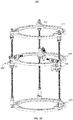
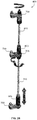
- FIGS. 24-28 there is shown an embodiment of a bone transport frame 100".
- a difference between the bone transport frame 100" shown in FIGS. 24-28 and previous examples is that medial ring 240 does not have the capability of horizontal translation.
- FIGS. 24-28 the embodiment shown in FIGS. 24-28 is obtained by taking the example of the bone transport frame 100' shown in FIGS. 22-23 , removing the translating bolt 730 and accessories, and directly attaching the ball jointed flange 705 to the medial ring 240.
- the ball jointed flange 705 can connect to the medial ring 240 by virtue of a retaining pin 720 that extends through both a through-hole 210 of the medial ring 240 and through an anterior through-hole 740 of the ball jointed flange 705.
Landscapes
- Health & Medical Sciences (AREA)
- Orthopedic Medicine & Surgery (AREA)
- Life Sciences & Earth Sciences (AREA)
- Surgery (AREA)
- Biomedical Technology (AREA)
- Engineering & Computer Science (AREA)
- Nuclear Medicine, Radiotherapy & Molecular Imaging (AREA)
- Heart & Thoracic Surgery (AREA)
- Medical Informatics (AREA)
- Molecular Biology (AREA)
- Animal Behavior & Ethology (AREA)
- General Health & Medical Sciences (AREA)
- Public Health (AREA)
- Veterinary Medicine (AREA)
- Surgical Instruments (AREA)
Claims (10)
- Knochentransportrahmen (100"), aufweisend:einen ersten Ring (220) mit einer ersten oberen Ringfläche (285) und mit einer ersten zentralen Achse, die orthogonal zur ersten oberen Ringfläche (285) ist;einen zweiten Ring (240) mit einer zweiten oberen Ringfläche (285) und mit einer zweiten zentralen Achse, die orthogonal zur zweiten oberen Ringfläche (285) ist; undeine Vielzahl von länglichen Streben (310), welche mit dem ersten Ring (220) und dem zweiten Ring (240) gekoppelt sind, wobei die Vielzahl von länglichen Streben (310) jeweils ein erstes einstellbares Element (400) umfassen; undeine Vielzahl von Ringtransportanordnungen (150'), die den zweiten Ring (240) mit der Vielzahl von Streben (310) drehbar koppeln,wobei jede längliche Strebe eine an der ersten oberen Ringfläche (285) befestigte zentralen Achse aufweist, wobei die Drehung eines der Vielzahl von ersten einstellbaren Elementen (400) mindestens eines aus der Vielzahl von Ringtransportanordnungen (150') und aus dem zweiten Ring (240) entweder in proximaler oder distaler vertikaler Richtung in Bezug auf den ersten Ring (220) transportiert, wobei jede der Vielzahl von Ringtransportanordnungen (150') ein Gelenk (705) umfasst, welches um eine dreidimensionale Achse schwenken kann um zu ermöglichen, dass sich der zweite Ring (240) dreht, so dass die zweite obere Ringfläche (285) des zweiten Rings (240) nicht parallel zu der ersten oberen Ringfläche (285) des ersten Rings (220) ist, und wobei horizontale Verschiebung des zweiten Rings (240) im Wesentlichen verhindert ist, so dass es der zweiten zentralen Achse des zweiten Rings im Wesentlichen verhindert ist, sich zu oder weg von der zentralen Achsen der Vielzahl der länglichen Streben zu verschieben, ferner einen dritten Ring (260) mit einer dritten oberen Ringfläche (285) und mit einer dritten zentralen Achse, die orthogonal zur dritten oberen Ringfläche (285) ist, aufweisend, wobei der dritte Ring (260) mit der Vielzahl von länglichen Streben (310) gekoppelt ist, wobei der dritte Ring (260) zu dem zweiten Ring (240) beabstandet angeordnet ist und wobei der zweite Ring (220) zu dem ersten Ring beabstandet angeordnet ist.
- Knochentransportrahmen nach Anspruch 1, wobei der erste Ring (220) und der zweite Ring (240) jeweils eine Vielzahl von Durchgangslöcher aufweisen, welche sich durch die oberen und unteren Oberflächen der jeweiligen Ringe erstrecken.
- Knochentransportrahmen nach Anspruch 2, ferner eine Vielzahl von Stifthalteelementen und Knochenstiften aufweisend, welche dazu eingerichtet sind, den ersten Ring (220) bzw. den zweiten Ring (240) mit einem ersten Knochensegment (820) bzw. einem zweiten Knochensegment (840) zu koppeln.
- Knochentransportrahmen nach Anspruch 3, wobei jedes Stifthalteelement betriebsfähig mit einem entsprechenden der Durchgangslöcher des ersten Rings (220) oder des zweiten Rings (240) gekoppelt ist.
- Knochentransportrahmen nach Anspruch 2, ferner eine Vielzahl von Drahthalteelementen und Knochendrähten aufweisend, welche dazu eingerichtet sind, den ersten Ring (220) bzw. den zweiten Ring (240) mit einem ersten Knochensegment (820) bzw. einem zweiten Knochensegment (840) zu koppeln.
- Knochentransportrahmen nach Anspruch 5, wobei jedes Drahthalteelement betriebsfähig mit einem entsprechenden der Durchgangslöcher des ersten Rings (220) oder des zweiten Rings (240) gekoppelt ist.
- Knochentransportrahmen nach einem der Ansprüche 1 bis 6, wobei das erste einstellbare Element (400) jeder länglichen Strebe (310) am proximalen Endabschnitt der länglichen Strebe (310) angeordnet ist.
- Knochentransportrahmen nach einem der Ansprüche 1 bis 7, wobei das Gelenk (705) ein Kugelgelenkflansch (705) ist und wobei die Ringtransportanordnungen jeweils einen Schnelllösemechanismus (600) und ein Verriegelungselement (620) umfassen, wobei ein erster Abschnitt jedes Kugelgelenkflansches (705) mit dem zweiten Ring (240) gekoppelt ist und ein zweiter Abschnitt jedes Kugelgelenkflansches (705) mit einer entsprechenden länglichen Strebe (310) gekoppelt ist, wobei der zweite Abschnitt des Kugelgelenkflansches (705) ein Kugelgelenk in Gestalt eines Kragens (595) umfasst, welcher eine Hyperbelform hat, wobei sich die entsprechende längliche Strebe (310) durch eine Öffnung im Kragen (595) erstreckt, um dem zweiten Ring (240) zu ermöglichen sich in Bezug auf den ersten Ring (220) zu drehen, so dass die zweite zentrale Achse des zweiten Rings (240) schräg zu der ersten zentralen Achse (220) des ersten Rings (220) ist, wobei das Verriegelungselement (620) im Wesentlichen einer Form des hyperbolischen Kragens (595) entspricht und einen verriegelten und einen entriegelten Zustand aufweist, und wobei wenn sich das Verriegelungselement (620) im entriegelten Zustand befindet, ist der zweite Ring (240) frei um sich zu bewegen, so dass die zweite zentrale Achse des zweiten Rings (240) schräg zu den zentralen Achsen der länglichen Streben ist.
- Knochentransportrahmen nach Anspruch 8, wobei der erste Abschnitt des Kugelgelenkflansches (705) mit dem zweiten Ring (240) über einem Haltestift (720) gekoppelt ist, welcher sich durch ein Durchgangsloch des zweiten Rings (240) und ein entsprechendes Durchgangsloch (240) des Kugelgelenkflansches (705) erstreckt.
- Knochentransportrahmen nach Anspruch 8, wobei der erste Abschnitt des Kugelgelenkflansches (705) mindestens zwei Durchgangslöcher (240) umfasst und wobei der zweite Abschnitt des Kugelgelenkflansches (705) mindestens ein Durchgangloch aufweist.
Applications Claiming Priority (2)
| Application Number | Priority Date | Filing Date | Title |
|---|---|---|---|
| US13/592,832 US9101398B2 (en) | 2012-08-23 | 2012-08-23 | Bone transport external fixation frame |
| EP13180720.8A EP2700370B1 (de) | 2012-08-23 | 2013-08-16 | Externer Befestigungsrahmen für Knochentransport |
Related Parent Applications (2)
| Application Number | Title | Priority Date | Filing Date |
|---|---|---|---|
| EP13180720.8A Division EP2700370B1 (de) | 2012-08-23 | 2013-08-16 | Externer Befestigungsrahmen für Knochentransport |
| EP13180720.8A Division-Into EP2700370B1 (de) | 2012-08-23 | 2013-08-16 | Externer Befestigungsrahmen für Knochentransport |
Publications (3)
| Publication Number | Publication Date |
|---|---|
| EP3092961A2 EP3092961A2 (de) | 2016-11-16 |
| EP3092961A3 EP3092961A3 (de) | 2017-01-18 |
| EP3092961B1 true EP3092961B1 (de) | 2019-05-01 |
Family
ID=49083518
Family Applications (2)
| Application Number | Title | Priority Date | Filing Date |
|---|---|---|---|
| EP13180720.8A Active EP2700370B1 (de) | 2012-08-23 | 2013-08-16 | Externer Befestigungsrahmen für Knochentransport |
| EP16170790.6A Active EP3092961B1 (de) | 2012-08-23 | 2013-08-16 | Externer befestigungsrahmen für knochentransport |
Family Applications Before (1)
| Application Number | Title | Priority Date | Filing Date |
|---|---|---|---|
| EP13180720.8A Active EP2700370B1 (de) | 2012-08-23 | 2013-08-16 | Externer Befestigungsrahmen für Knochentransport |
Country Status (2)
| Country | Link |
|---|---|
| US (5) | US9101398B2 (de) |
| EP (2) | EP2700370B1 (de) |
Families Citing this family (45)
| Publication number | Priority date | Publication date | Assignee | Title |
|---|---|---|---|---|
| GB201008281D0 (en) | 2010-05-19 | 2010-06-30 | Nikonovas Arkadijus | Indirect analysis and manipulation of objects |
| US11141196B2 (en) | 2010-08-11 | 2021-10-12 | Stryker European Operations Holdings Llc | External fixator system |
| US9101398B2 (en) | 2012-08-23 | 2015-08-11 | Stryker Trauma Sa | Bone transport external fixation frame |
| WO2014055202A1 (en) * | 2012-09-06 | 2014-04-10 | Solana Surgical LLC | External fixator |
| ITGE20120093A1 (it) * | 2012-09-14 | 2014-03-15 | Mikai S P A | Fissatore circolare esterno |
| US9204937B2 (en) * | 2013-02-19 | 2015-12-08 | Stryker Trauma Gmbh | Software for use with deformity correction |
| US9675382B2 (en) | 2013-03-13 | 2017-06-13 | DePuy Synthes Products, Inc. | External bone fixation device |
| US9039706B2 (en) | 2013-03-13 | 2015-05-26 | DePuy Synthes Products, Inc. | External bone fixation device |
| EP2967674B1 (de) | 2013-03-15 | 2024-02-21 | Biomet C.V. | Polyaxiales gehäuse für einen fixateuer externe |
| US9717528B2 (en) | 2014-04-01 | 2017-08-01 | Stryker European Holdings I, Llc | External fixator with Y strut |
| CN104161578A (zh) * | 2014-08-20 | 2014-11-26 | 王峤 | 长骨骨折、半环单侧穿针整复外固定架 |
| US11266444B2 (en) * | 2015-02-06 | 2022-03-08 | University Of Houston System | External fixation device with absorption material for reducing radiofrequency induced heat transfer and method thereof |
| CN204863429U (zh) * | 2015-04-29 | 2015-12-16 | 胡成吉 | 一字型手爪式髌骨外固定器 |
| WO2016193154A1 (en) | 2015-05-29 | 2016-12-08 | Université Catholique de Louvain | External fixation system |
| EP3373833B1 (de) * | 2015-11-12 | 2021-09-22 | Wright Medical Technology, Inc. | Kreisförmiges fixiersystem |
| CA3014098C (en) * | 2016-02-09 | 2024-06-04 | Amdt Holdings, Inc. | External bone fixation systems |
| US10251705B2 (en) | 2016-06-02 | 2019-04-09 | Stryker European Holdings I, Llc | Software for use with deformity correction |
| US10010350B2 (en) | 2016-06-14 | 2018-07-03 | Stryker European Holdings I, Llc | Gear mechanisms for fixation frame struts |
| ES3012792T3 (en) | 2016-06-19 | 2025-04-10 | Orthospin Ltd | User interface for strut device |
| US10835318B2 (en) | 2016-08-25 | 2020-11-17 | DePuy Synthes Products, Inc. | Orthopedic fixation control and manipulation |
| RU2635463C1 (ru) * | 2016-08-31 | 2017-11-13 | Валерий Викторович Педдер | Компрессионно-дистракционный аппарат |
| US10874433B2 (en) | 2017-01-30 | 2020-12-29 | Stryker European Holdings I, Llc | Strut attachments for external fixation frame |
| RU2669480C1 (ru) * | 2017-09-18 | 2018-10-11 | федеральное государственное бюджетное учреждение "Российский научный центр "Восстановительная травматология и ортопедия" имени академика Г.А. Илизарова" Министерства здравоохранения Российской Федерации ФГБУ "РНЦ "ВТО" им. акад. Г.А. Илизарова" Минздрава России | Крепежный элемент для аппарата наружной фиксации костей и инструмент для его установки |
| CN110495937B (zh) * | 2018-05-18 | 2024-08-16 | 武汉迈瑞科技有限公司 | 环形外固定支架和固定装置 |
| US11883074B2 (en) * | 2018-09-07 | 2024-01-30 | Orthex, LLC | Hole transporter |
| CN109157276A (zh) * | 2018-09-26 | 2019-01-08 | 深圳市龙华区中心医院 | 一种数字化可控的恒力骨搬移装置 |
| US12274475B2 (en) | 2018-10-04 | 2025-04-15 | Peter M. Stevens | Automated coupled torsional fixators and method of use |
| WO2020072392A1 (en) | 2018-10-04 | 2020-04-09 | Peter Stevens | Coupled torsional fixator and method of use |
| WO2020086669A1 (en) | 2018-10-24 | 2020-04-30 | Glw, Inc. | External fixation stabilizers, systems, kits, and methods |
| US11439436B2 (en) | 2019-03-18 | 2022-09-13 | Synthes Gmbh | Orthopedic fixation strut swapping |
| EP3946100B1 (de) * | 2019-03-26 | 2023-10-11 | Smith & Nephew, Inc. | Externe fixierstrebe |
| US11304757B2 (en) | 2019-03-28 | 2022-04-19 | Synthes Gmbh | Orthopedic fixation control and visualization |
| US11334997B2 (en) | 2020-04-03 | 2022-05-17 | Synthes Gmbh | Hinge detection for orthopedic fixation |
| EP4135606B1 (de) * | 2020-04-15 | 2025-10-22 | Smith&Nephew, Inc. | Umrüstsatz für ein externes fixationssystem |
| US11457950B2 (en) | 2020-04-27 | 2022-10-04 | DePuy Synthes Products, Inc. | Locking system and method |
| RU2750521C1 (ru) * | 2020-09-14 | 2021-06-29 | Федеральное Государственное бюджетное образовательное учреждение высшего образования Дагестанский государственный медицинский университет Министерства здравоохранения Российской Федерации Даггосмедуниверситет | Устройство для первичной стабилизации диафизарных переломов голени при политравме |
| WO2022201017A1 (en) | 2021-03-22 | 2022-09-29 | Nelson Saldanha Kiran Antony | Stable locking fixation of threaded bone pins and other components of ring external fixator |
| US12364510B2 (en) | 2021-12-20 | 2025-07-22 | Stryker European Operations Limited | Quick release mechanism for strut |
| US20230248393A1 (en) * | 2022-02-10 | 2023-08-10 | Nuvasive Specialized Orthopedics, Inc. | External bone fixation device with modular driving element |
| US11896267B2 (en) | 2022-02-15 | 2024-02-13 | Stryker European Operations Limited | Controller module for strut adjustment |
| US12268360B2 (en) * | 2022-05-16 | 2025-04-08 | Medtronic Navigation, Inc. | Manual hexapod locking mechanism |
| CN116509611B (zh) * | 2023-04-27 | 2025-08-22 | 湖州师范学院 | 一种骨缺损修复用固定结构 |
| US12453583B2 (en) | 2023-12-04 | 2025-10-28 | BioDynamik, Inc. | Systems and methods for transport and tissue distraction |
| US20250255648A1 (en) | 2024-02-08 | 2025-08-14 | Stryker European Operations Limited | Mechanisms for Strut Length Measurement |
| CN121059257A (zh) * | 2025-10-14 | 2025-12-05 | 中国人民解放军总医院第五医学中心 | 一种骨缺损修复外固定装置 |
Family Cites Families (264)
| Publication number | Priority date | Publication date | Assignee | Title |
|---|---|---|---|---|
| US6214A (en) | 1849-03-20 | Surgical apparatus for fractured or injured ankles | ||
| US2055024A (en) | 1934-08-07 | 1936-09-22 | Jr Joseph E Bittner | Fracture reducing splint |
| US2035952A (en) | 1935-05-20 | 1936-03-31 | Joe J Ettinger | Fracture reduction apparatus |
| US2291747A (en) | 1940-10-01 | 1942-08-04 | Testrite Instr Company Inc | Tripod |
| US2393831A (en) | 1942-12-29 | 1946-01-29 | Stader Otto | Bone splint |
| US2406987A (en) | 1943-01-04 | 1946-09-03 | Anderson Roger | Fracture splint |
| US2333033A (en) | 1943-06-11 | 1943-10-26 | Leslie E Mraz | Bone splint |
| US2391537A (en) | 1943-09-27 | 1945-12-25 | Anderson Roger | Ambulatory rotating reduction and fixation splint |
| US2883219A (en) | 1956-01-23 | 1959-04-21 | Slide Lock Ltd | Adjustable holding or locking devices |
| US3863037A (en) | 1970-09-03 | 1975-01-28 | Nelco Corp | Electrical box hanger structure |
| US3691788A (en) | 1970-09-10 | 1972-09-19 | Ralph Mazziotti | Stay-rite flex joint |
| CH536107A (de) | 1971-03-16 | 1973-04-30 | Paolo Prof Dr Med Riniker | Fixator für Diaphysenbrüche |
| SU517196A1 (ru) | 1974-07-22 | 1977-09-25 | Центральный Ордена Трудового Красного Знамени Научно-Исследовательского Институт Травматологии И Ортопедии | Аппарат дл репозиции и фиксации костных отломков |
| US3977397A (en) | 1974-11-27 | 1976-08-31 | Kalnberz Viktor Konstantinovic | Surgical compression-distraction instrument |
| US3941123A (en) | 1975-05-20 | 1976-03-02 | Mstislav Vasilievich Volkov | Apparatus for joint movement restitution |
| US3985127A (en) | 1975-06-11 | 1976-10-12 | Mstislav Vasilievich Volkov | Apparatus for surgical treatment of the knee joint |
| CH596826A5 (en) | 1975-12-18 | 1978-03-31 | Tsnii Travmatologii I Ortopedi | Surgical braces for fractured bones |
| CA1077363A (en) | 1976-08-09 | 1980-05-13 | Richard F. Kronner | Fracture reducing and joint immobilizing apparatus |
| US4100919A (en) | 1976-12-08 | 1978-07-18 | Tsentralny Nauchno-Issledovatelsky Institut Travmatologii I Ortopedii Imeni N.N. Priorova | Apparatus for surgical treatment of bones and joints |
| US4185623A (en) | 1978-07-18 | 1980-01-29 | Oganesian Oganes V | Apparatus for restoration of hip joint mobility |
| FR2439002A1 (fr) | 1978-10-16 | 1980-05-16 | Kronner Richard | Appareil en vue d'immobiliser les articulations et reduire les fractures |
| CH630798A5 (fr) | 1979-01-16 | 1982-07-15 | Jaquet Orthopedie | Fixateur externe pour osteosynthese. |
| US4308863A (en) | 1979-10-18 | 1982-01-05 | Ace Orthopedic Manufacturing, Inc. | External fixation device |
| US4450834A (en) | 1979-10-18 | 1984-05-29 | Ace Orthopedic Manufacturing, Inc. | External fixation device |
| US4403606A (en) | 1980-05-09 | 1983-09-13 | The Regents Of The University Of California | Compatible internal bone fixation plate |
| US4338927A (en) | 1981-03-16 | 1982-07-13 | Volkov Mstislav V | Device for restoring the function of the lower extremities |
| DE3114455C2 (de) | 1981-04-09 | 1986-11-06 | Central'nyj naučno-issledovatel'skij institut travmatologii i orteopedii imeni N.N. Priorova, Moskau/Moskva | Vorrichtung zur Rekonvaleszenzbehandlung der Unterextremitäten |
| US4520983A (en) | 1981-11-03 | 1985-06-04 | Peterson Mfg. Co. | Mirror assembly |
| US4548199A (en) | 1981-11-13 | 1985-10-22 | Agee John M | Fracture splint |
| US4554915A (en) | 1983-03-08 | 1985-11-26 | Richards Medical Company | Bone fixation frame |
| US4611586A (en) | 1983-10-06 | 1986-09-16 | John M. Agee | Articulated Colles' fracture splint |
| US4889111A (en) | 1984-02-08 | 1989-12-26 | Ben Dov Meir | Bone growth stimulator |
| CH664079A5 (fr) | 1985-01-24 | 1988-02-15 | Jaquet Orthopedie | Element d'arceau et fixateur externe pour osteosynthese et osteoplastie. |
| FR2576774B1 (fr) | 1985-02-07 | 1990-03-30 | Issoire Aviat Sa | Dispositif de positionnement tridimensionnel de deux pieces quelconques, en particulier de deux parties d'os, et permettant de modifier ledit positionnement |
| AT384360B (de) | 1985-09-18 | 1987-11-10 | Kurgansky Niiex I Klinicheskoi | Antrieb fuer kompressions-distraktionsapparate |
| CH672089A5 (de) | 1985-12-16 | 1989-10-31 | Sogeva Sa | |
| FR2595045B1 (fr) | 1986-02-28 | 1991-12-27 | Hardy Jean Marie | Dispositif d'immobilisation d'un element osseux, notamment pour intervention orthopedique |
| US4730608A (en) | 1986-03-05 | 1988-03-15 | Schlein Allen P | External bone-anchoring fixator |
| US4905680A (en) | 1986-10-27 | 1990-03-06 | Johnson & Johnson Orthopaedics, Inc. | Absorbable bone plate |
| WO1989011254A1 (fr) | 1988-05-26 | 1989-11-30 | Vsesojuzny Kurgansky Nauchny Tsentr ''vosstanovite | Appareil de compression-traction pour osteosynthese |
| DE3720242A1 (de) | 1987-06-19 | 1988-12-29 | Schewior Thomas Dr Med | Ringfixateur zum einrichten von knochenabschnitten und/oder -fragmenten und zum erzeugen von knochen-spannlagen |
| US4819496A (en) | 1987-11-17 | 1989-04-11 | The United States Of America As Represented By The Secretary Of The Air Force | Six degrees of freedom micromanipulator |
| JPH03502535A (ja) | 1988-07-25 | 1991-06-13 | フセソユズニ クルガンスキ ナウチニ ツェントル“ボススタノビテルナヤ トラフマトロギア イ オルトペディア” | 手の形成的復元のための伸延装置 |
| US4973332A (en) | 1988-09-12 | 1990-11-27 | Hospital For Joint Diseases | Attachment for femur sliding screw plate |
| CH678485A5 (de) | 1988-12-15 | 1991-09-30 | Jaquet Orthopedie | |
| US5207676A (en) | 1989-02-27 | 1993-05-04 | Jaquet Orthopedie S.A. | External fixator with controllable damping |
| US5112331A (en) | 1989-06-15 | 1992-05-12 | Vel Miletich | Orthopedic pins for external fixator |
| CH680769A5 (de) | 1989-08-23 | 1992-11-13 | Jaquet Orthopedie | |
| US5028180A (en) | 1989-09-01 | 1991-07-02 | Sheldon Paul C | Six-axis machine tool |
| US5179525A (en) | 1990-05-01 | 1993-01-12 | University Of Florida | Method and apparatus for controlling geometrically simple parallel mechanisms with distinctive connections |
| IT1244249B (it) | 1990-08-03 | 1994-07-08 | Ascanio Campopiano | Manipolatore per l'esecuzione di manovre riduttive in uso in medicina traumatologica ed ortopedica applicabile a fissatori esterni. |
| US5062844A (en) | 1990-09-07 | 1991-11-05 | Smith & Nephew Richards Inc. | Method and apparatus for the fixation of bone fractures, limb lengthening and the correction of deformities |
| US5074866A (en) | 1990-10-16 | 1991-12-24 | Smith & Nephew Richards Inc. | Translation/rotation device for external bone fixation system |
| CN2080829U (zh) | 1990-12-13 | 1991-07-17 | 刘维胜 | 长骨干万能复位固定器 |
| WO1992014426A1 (en) | 1991-02-20 | 1992-09-03 | Danek Medical, Inc. | Improved external fixation frame assembly |
| JP3058935B2 (ja) | 1991-04-26 | 2000-07-04 | 株式会社東芝 | 基準電流発生回路 |
| US5275598A (en) | 1991-10-09 | 1994-01-04 | Cook Richard L | Quasi-isotropic apparatus and method of fabricating the apparatus |
| IT1259768B (it) | 1992-04-30 | 1996-03-26 | Lima Spa | Colonna telescopica regolabile per allungamento e/o riduzione delle ossa |
| US5279176A (en) | 1992-07-20 | 1994-01-18 | The United States Of America As Represented By The Administrator Of The National Aeronautics And Space Administration | Six-degree-of-freedom parallel "minimanipulator" with three inextensible limbs |
| WO1994004087A1 (en) | 1992-08-24 | 1994-03-03 | Synthes Ag, Chur | External fixation device for osteosynthesis |
| US5391167A (en) | 1992-09-01 | 1995-02-21 | Ortho-Motion, Inc. | Articulating external fixation device |
| US5545165A (en) | 1992-10-09 | 1996-08-13 | Biedermann Motech Gmbh | Anchoring member |
| US5658283A (en) | 1995-02-15 | 1997-08-19 | Huebner; Randall J. | External fixator for repairing fractures |
| US5405347A (en) | 1993-02-12 | 1995-04-11 | Zimmer, Inc. | Adjustable connector for external fixation rods |
| DE59406392D1 (de) | 1993-02-18 | 1998-08-13 | Endocare Ag | Vorrichtung zur verlängerung von knochen |
| IT1262781B (it) | 1993-03-15 | 1996-07-04 | Giovanni Faccioli | Attrezzo e metodo per la riduzione esterna di fratture |
| US6162234A (en) | 1993-03-23 | 2000-12-19 | Freedland; Yosef | Adjustable button cinch anchor orthopedic fastener |
| US5353504A (en) | 1993-04-30 | 1994-10-11 | Pai Chung Jen | Motorized scissors |
| US5358504A (en) | 1993-05-05 | 1994-10-25 | Smith & Nephew Richards, Inc. | Fixation brace with focal hinge |
| US5372597A (en) | 1993-05-12 | 1994-12-13 | Smith & Nephew Richards, Inc. | Supination-pronation device |
| US5451225A (en) | 1993-06-10 | 1995-09-19 | Texas Scottish Rite Hospital For Crippled Children | Fastener for external fixation device wires and pins |
| US5766173A (en) | 1993-06-10 | 1998-06-16 | Texas Scottish Rite Hospital For Children | Distractor mechanism for external fixation device |
| US5466237A (en) | 1993-11-19 | 1995-11-14 | Cross Medical Products, Inc. | Variable locking stabilizer anchor seat and screw |
| GB9325698D0 (en) | 1993-12-15 | 1994-02-16 | Richardson James B | Patient-operated orthopedic device |
| ITVR940019A1 (it) | 1994-03-07 | 1995-09-07 | Ortofix Srl | Attrezzo ortopedico, particolarmente per la correzione graduale esterna di fratture. |
| US5591169A (en) | 1994-06-14 | 1997-01-07 | Benoist; Louis | Device and method for positioning and holding bone fragments in place |
| DE4421223A1 (de) | 1994-06-17 | 1995-12-21 | Fischer Juergen | Gerät zur variablen Fixierung organischer und anorganischer fester Substanzen |
| US5496319A (en) | 1994-06-27 | 1996-03-05 | Zimmer, Inc. | External fixation apparatus |
| US5683389A (en) | 1994-12-05 | 1997-11-04 | Smith & Nephew, Inc. | External fixator for distal radius fractures |
| US5568993A (en) | 1994-12-21 | 1996-10-29 | The United States Of America As Represented By The Secretary Of Commerce | Strut structure and rigid joint therefor |
| US5728095A (en) | 1995-03-01 | 1998-03-17 | Smith & Nephew, Inc. | Method of using an orthopaedic fixation device |
| US5971984A (en) | 1995-03-01 | 1999-10-26 | Smith & Nephew, Inc. | Method of using an orthopaedic fixation device |
| EP0814714B1 (de) * | 1995-03-01 | 2005-10-05 | Smith & Nephew, Inc. | Räumlicher rahmen |
| IL114714A (en) | 1995-07-24 | 1998-12-27 | Hadasit Med Res Service | Orthopedic fixator |
| DE29515007U1 (de) | 1995-09-19 | 1995-12-07 | Pennig, Dietmar, Dr.med., 50935 Köln | Osteosynthesehilfsmittel |
| US5797191A (en) | 1996-09-25 | 1998-08-25 | University Of Florida | Parallel kinematic structure for spatial positioning devices and method of initializing same |
| US5846245A (en) | 1995-10-20 | 1998-12-08 | New York University | Bone-adjusting device |
| US5725526A (en) | 1995-11-27 | 1998-03-10 | Zimmer, Inc. | Transport carriage for an external fixator |
| US6099217A (en) | 1995-12-20 | 2000-08-08 | Wiegand; Alexander Konrad | Device for spatially moving a body with three to six degrees of freedom in a controlled manner |
| US6007535A (en) | 1996-01-03 | 1999-12-28 | John M. Rayhack | Multi-plane bone distraction system |
| IT1289078B1 (it) | 1996-02-21 | 1998-09-25 | Orthofix Srl | Dispositivo fissatore esterno per la chirurgia ossea |
| DE69706403T2 (de) | 1996-02-22 | 2002-05-29 | Depuy Orthopaedics, Inc. | Externe befestigungsvorrichtung mit ringen aus kompositmaterial |
| US5976133A (en) | 1997-04-23 | 1999-11-02 | Trustees Of Tufts College | External fixator clamp and system |
| US5863292A (en) | 1996-09-26 | 1999-01-26 | Tosic; Aleksandar | Articulated external orthopedic fixation system and method of use |
| US5870834A (en) | 1996-10-22 | 1999-02-16 | Sheldon/Van Someren, Inc. | Six-axis metrology sensor device |
| DE29619711U1 (de) | 1996-11-13 | 1998-03-12 | Synthes AG Chur, Chur, Graubünden | Vorrichtung zum Reponieren von Knochenfrakturfragmenten |
| FR2756025B1 (fr) | 1996-11-15 | 1998-12-24 | Const Mecaniques Des Vosges | Structure de cardan pour la liaison articulee d'un hexapode |
| US6485494B1 (en) | 1996-12-20 | 2002-11-26 | Thomas T. Haider | Pedicle screw system for osteosynthesis |
| US5776132A (en) | 1996-12-26 | 1998-07-07 | Blyakher; Arkady | External fixation assembly |
| AU725487B2 (en) | 1997-01-22 | 2000-10-12 | Synthes Gmbh | Device for connecting a longitudinal bar to a pedicle screw |
| US5797908A (en) | 1997-02-04 | 1998-08-25 | Bristol-Myers Squibb Company | External fixator assembly and clamp therefor |
| US5713897A (en) | 1997-03-06 | 1998-02-03 | Goble; E. Marlowe | Anterior cruciate ligament tensioning device and method for its use |
| US5897555A (en) | 1997-05-15 | 1999-04-27 | Wright Medical Technology, Inc. | External fixation system and method |
| GB2324038A (en) | 1997-04-11 | 1998-10-14 | Univ Keele | Fracture reduction device |
| US5885282A (en) | 1997-05-09 | 1999-03-23 | The Regents Of The University Of California | Apparatus for treatment of fracture and malunion of the distal radius |
| US5776173A (en) | 1997-06-04 | 1998-07-07 | Madsen, Jr.; Ronald E. | Programmable interferential stimulator |
| US5919192A (en) | 1997-06-10 | 1999-07-06 | Cottec Orthopaedic Technologies Development Ltd. | Compression-distraction apparatus for treatment of a bone fracture |
| US5891143A (en) | 1997-10-20 | 1999-04-06 | Smith & Nephew, Inc. | Orthopaedic fixation plate |
| US5931837A (en) | 1997-12-09 | 1999-08-03 | University Of Iowa Research Foundation | Method and apparatus for external fixation of an ankle |
| US6010501A (en) | 1997-12-15 | 2000-01-04 | Electro-Biology, Inc. | Method and apparatus for external fixation of small bones |
| WO1999038646A1 (en) | 1998-02-03 | 1999-08-05 | Hexel Corporation | Systems and methods employing a rotary track for machining and manufacturing |
| US5921985A (en) | 1998-02-10 | 1999-07-13 | Texas Scottish Rite Hospital | External fixation device and method |
| US6021579A (en) | 1998-04-01 | 2000-02-08 | Joseph M. Schimmels | Spatial parallel compliant mechanism |
| AT408317B (de) | 1998-04-09 | 2001-10-25 | Mepura Metallpulver | Verfahren zur herstellung von schaummetall-formkörpern |
| US5997537A (en) | 1998-05-28 | 1999-12-07 | Electro Biology, Inc. | Ring system for external fixation of bone and related method |
| US6565565B1 (en) | 1998-06-17 | 2003-05-20 | Howmedica Osteonics Corp. | Device for securing spinal rods |
| US6090111A (en) | 1998-06-17 | 2000-07-18 | Surgical Dynamics, Inc. | Device for securing spinal rods |
| US6030386A (en) | 1998-08-10 | 2000-02-29 | Smith & Nephew, Inc. | Six axis external fixator strut |
| US6013081A (en) | 1998-09-09 | 2000-01-11 | Sulzer Orthopedics Inc. | Apparatus and method for anterior and posterior referenced sizing and distal femur resection |
| EP1016381B1 (de) | 1998-11-23 | 2003-12-10 | Hraklis Kourtis | Äusserliche Befestigung mit teleskopischem Halter für einen Stift oder einen Arm |
| CH693164A5 (fr) | 1998-12-29 | 2003-03-27 | Stryker Trauma Sa | Dispositif de positionnement et de blocage. |
| US6129727A (en) | 1999-03-02 | 2000-10-10 | Smith & Nephew | Orthopaedic spatial frame apparatus |
| US6245071B1 (en) | 1999-03-10 | 2001-06-12 | Synthes (U.S.A.) | External fixation device for bone |
| US6497548B1 (en) | 1999-08-05 | 2002-12-24 | Shambhu Nath Roy | Parallel kinematics mechanism with a concentric sperical joint |
| DE69930973D1 (de) | 1999-08-30 | 2006-05-24 | Smith & Nephew Inc | Um sechs achsen einstellbarer stab für äusseren fixateur |
| WO2001022892A1 (en) | 1999-09-28 | 2001-04-05 | Bundgaard Kristian G | Method of measuring bone strength, apparatus for measuring bone strength and fixation device |
| US6342052B1 (en) | 1999-11-02 | 2002-01-29 | Hector D. Allende | Anorectal apparatus |
| US6277118B1 (en) | 2000-01-31 | 2001-08-21 | Electro-Biology, Inc. | External fixator including an angular correction module and related method |
| US20020010465A1 (en) | 2000-01-31 | 2002-01-24 | Ja Kyo Koo | Frame fixator and operation system thereof |
| US6613049B2 (en) | 2000-02-02 | 2003-09-02 | Robert A. Winquist | Adjustable bone stabilizing frame system |
| JP3535064B2 (ja) | 2000-03-07 | 2004-06-07 | カネボウ株式会社 | 熱可塑性エラストマー不織布ロールの製造方法並びに製造装置 |
| US6423061B1 (en) | 2000-03-14 | 2002-07-23 | Amei Technologies Inc. | High tibial osteotomy method and apparatus |
| US6701174B1 (en) | 2000-04-07 | 2004-03-02 | Carnegie Mellon University | Computer-aided bone distraction |
| ES2273674T3 (es) | 2000-04-19 | 2007-05-16 | Synthes Gmbh | Dispositivo para la union articulada de dos cuerpos. |
| DE60032736T2 (de) | 2000-05-09 | 2007-11-08 | Orthofix S.R.L., Bussolengo | Ringfixateur |
| ES2277825T3 (es) | 2000-05-09 | 2007-08-01 | Orthofix S.R.L. | Componente para asegurar un fijador de anillo utilizado en cirugia ortopedica. |
| DE10025405C2 (de) | 2000-05-23 | 2003-03-20 | Gert Dieter Hohenoecker | Bauteil zur form- und kraftschlüssigen Welle-Nabe-Verbindung |
| NL1015284C2 (nl) | 2000-05-24 | 2001-11-27 | Gerrit Johannes Termaten | Fixatie-inrichting voor orthopedische toepassingen. |
| JP2004504884A (ja) | 2000-07-28 | 2004-02-19 | ジンテーズ アクチエンゲゼルシャフト クール | 脊髄固定システム |
| EP1184000A1 (de) | 2000-08-31 | 2002-03-06 | ORTHOFIX S.r.l. | Äusserer Fixateur zur Stabilisierung von Knochenbrüchen |
| US6355037B1 (en) | 2000-12-05 | 2002-03-12 | Smith & Nephew, Inc. | Apparatus and method of external skeletal support allowing for internal-external rotation |
| US6565564B2 (en) | 2000-12-14 | 2003-05-20 | Synthes U.S.A. | Multi-pin clamp and rod attachment |
| DE10101478C2 (de) | 2001-01-12 | 2003-03-27 | Biedermann Motech Gmbh | Verbindungselement |
| DK1238636T3 (da) | 2001-03-05 | 2007-01-02 | Orthofix Srl | Udvendig fastgörelsesindretning med idenfikationsmiddel |
| GB0107708D0 (en) | 2001-03-28 | 2001-05-16 | Imp College Innovations Ltd | Bone fixated,articulated joint load control device |
| US7147640B2 (en) | 2003-03-12 | 2006-12-12 | Acumed Llc | External fixator |
| GB0119104D0 (en) | 2001-08-06 | 2001-09-26 | Patterson Noble | Walking aid |
| WO2003024344A1 (en) | 2001-09-14 | 2003-03-27 | The Regents Of The University Of California | System and method for fusing spinal vertebrae |
| US7261713B2 (en) | 2001-10-09 | 2007-08-28 | Synthes (Usa) | Adjustable fixator |
| US6671975B2 (en) | 2001-12-10 | 2004-01-06 | C. William Hennessey | Parallel kinematic micromanipulator |
| US7311711B2 (en) | 2001-12-21 | 2007-12-25 | Cole J Dean | Surgical distractor frame |
| US7004943B2 (en) | 2002-02-04 | 2006-02-28 | Smith & Nephew, Inc. | Devices, systems, and methods for placing and positioning fixation elements in external fixation systems |
| US7048735B2 (en) | 2002-02-04 | 2006-05-23 | Smith & Nephew | External fixation system |
| US6860883B2 (en) | 2002-02-11 | 2005-03-01 | Pioneer Laboratories, Inc. | External fixation apparatus and method |
| WO2003086212A2 (en) | 2002-04-05 | 2003-10-23 | Smith & Nephew, Inc. | Orthopaedic fixation method and device |
| US6733502B2 (en) | 2002-05-15 | 2004-05-11 | Cross Medical Products, Inc. | Variable locking spinal screw having a knurled collar |
| ITBO20020309A1 (it) | 2002-05-20 | 2003-11-20 | Citieffe Srl | Fissatore esterno per il trattamento delle fratture delle ossa |
| US6652524B1 (en) | 2002-05-30 | 2003-11-25 | Millennium Medical Technologies, Inc. | Fixator with outrigger |
| US6746448B2 (en) | 2002-05-30 | 2004-06-08 | Millennium Medical Technologies, Inc. | Outrigger for bone fixator |
| US20040167518A1 (en) | 2002-07-12 | 2004-08-26 | Estrada Hector Mark | Radiolucent frame element for external bone fixators |
| US7449023B2 (en) | 2002-07-15 | 2008-11-11 | Ebi, Llc | Method and apparatus for the external fixation and correction of bone |
| US20040097944A1 (en) | 2002-07-30 | 2004-05-20 | Koman L. Andrew | Fixation device and method for treating contractures and other orthopedic indications |
| EP1549235A4 (de) | 2002-09-17 | 2010-05-05 | Extraortho Inc | EINSEITIGES FIXIERGERûT |
| US20040073212A1 (en) | 2002-10-15 | 2004-04-15 | Kim Jung Jae | Extracorporeal fixing device for a bone fracture |
| US20040133200A1 (en) | 2002-11-15 | 2004-07-08 | Ruch David S. | Apparatus and method for maintaining bones in a healing position |
| US7608074B2 (en) | 2003-01-10 | 2009-10-27 | Smith & Nephew, Inc. | External fixation apparatus and method |
| US20040156676A1 (en) | 2003-02-12 | 2004-08-12 | Brent Boudreaux | Fastener for variable mounting |
| US7377923B2 (en) | 2003-05-22 | 2008-05-27 | Alphatec Spine, Inc. | Variable angle spinal screw assembly |
| US7291148B2 (en) | 2003-06-03 | 2007-11-06 | John M. Agee Trustee Of The John M. Agee Trust | External fixator for Colles' fracture |
| US6964663B2 (en) | 2003-09-16 | 2005-11-15 | Ez Concepts Surgical Device Corporation | Combination bone fixation/immobilization apparatus |
| EP1522266A1 (de) | 2003-10-06 | 2005-04-13 | Stryker Trauma SA | Äusserliche Befestigungsvorrichtung |
| US6935805B2 (en) | 2003-10-16 | 2005-08-30 | Itt Manufacturing Enterprises, Inc. | High reliability precision latch |
| US7361176B2 (en) | 2003-12-31 | 2008-04-22 | Depuy Products, Inc. | External bone/joint fixation device |
| US7127660B2 (en) | 2004-01-14 | 2006-10-24 | Hitachi Global Storage Technologies Netherlands B.V. | Method, apparatus and program storage device for correcting a burst of errors together with a random error using shortened cyclic codes |
| US20050234448A1 (en) | 2004-03-19 | 2005-10-20 | Mccarthy James | Implantable bone-lengthening device |
| US7803158B2 (en) | 2004-03-26 | 2010-09-28 | Depuy Products, Inc. | Navigated pin placement for orthopaedic procedures |
| US7485121B2 (en) | 2004-05-04 | 2009-02-03 | Synthes (Usa) | Midface distractor |
| US20050248156A1 (en) | 2004-05-05 | 2005-11-10 | Pi-Hua Hsieh | Structure lamp pipe insert connector |
| US20060155276A1 (en) | 2005-01-11 | 2006-07-13 | Walulik Stephen B | Bone fixation assembly and related method |
| ES2313209T3 (es) | 2005-02-09 | 2009-03-01 | Stryker Trauma Sa | Dispositivo externo de fijacion, en particular para aumentar una distancia entre elementos de sujecion. |
| DE502005005095D1 (de) | 2005-02-09 | 2008-10-02 | Stryker Trauma Sa | Einsatz für ein Klemmelement, Klemmelement mit einem solchen Einsatz und daraus gebildete Gelenkverbindung |
| US8469958B2 (en) | 2005-02-15 | 2013-06-25 | Morphographics, Lc | Fixing block and method for stabilizing bone |
| US20060235383A1 (en) | 2005-03-07 | 2006-10-19 | Shane Hollawell | External fixator |
| US7815586B2 (en) | 2005-03-09 | 2010-10-19 | Ez Concepts Surgical Device Corporation | Adjustable restraint for the lower leg and/or foot |
| US20060229605A1 (en) | 2005-03-18 | 2006-10-12 | Olsen Ron A | Adjustable splint for osteosynthesis with incrementing assembly for adjustment in predetermined increments |
| US7588571B2 (en) | 2005-03-18 | 2009-09-15 | Ron Anthon Olsen | Adjustable splint for osteosynthesis with modular joint |
| DE202005005444U1 (de) | 2005-04-01 | 2005-06-02 | Tantum Ag | Fixationseinrichtung zum stabilen Verbinden wenigstens zweier Knochenteile eines gebrochenen Knochens sowie Fixationselement und Bausatz |
| US8758343B2 (en) | 2005-04-27 | 2014-06-24 | DePuy Synthes Products, LLC | Bone fixation apparatus |
| US7578822B2 (en) | 2005-04-29 | 2009-08-25 | Warsaw Orthopedic, Inc. | Instrument for compression or distraction |
| US7523911B2 (en) | 2005-05-02 | 2009-04-28 | Carnevali Jeffrey D | Telescoping pole mount |
| US20060276786A1 (en) | 2005-05-25 | 2006-12-07 | Brinker Mark R | Apparatus for accurately positioning fractured bone fragments toward facilitating use of an external ring fixator system |
| US7306601B2 (en) | 2005-06-10 | 2007-12-11 | Quantum Medical Concepts, Inc. | External fixation system with provisional brace |
| US8523858B2 (en) | 2005-06-21 | 2013-09-03 | DePuy Synthes Products, LLC | Adjustable fixation clamp and method |
| US7881771B2 (en) | 2005-08-03 | 2011-02-01 | The Hong Kong Polytechnic University | Bone reposition device, method and system |
| US20070055233A1 (en) | 2005-08-03 | 2007-03-08 | Brinker Mark R | Apparatus and method for repositioning fractured bone fragments using an arc shaped panel and half pins |
| US20070038217A1 (en) | 2005-08-09 | 2007-02-15 | Brown Daniel G | Orthopaedic fixation clamp and method |
| US8029505B2 (en) | 2005-08-25 | 2011-10-04 | Synthes Usa, Llc | External fixation system and method of use |
| US20070123857A1 (en) | 2005-10-27 | 2007-05-31 | Deffenbaugh Daren L | Orthopaedic joint, device and associated method |
| US7749224B2 (en) | 2005-12-08 | 2010-07-06 | Ebi, Llc | Foot plate fixation |
| US7422593B2 (en) | 2005-12-08 | 2008-09-09 | Ebi, L.P. | External fixation system |
| US7648524B2 (en) | 2005-12-23 | 2010-01-19 | Howmedica Osteonics Corp. | Porous tendon anchor |
| RU2357699C2 (ru) | 2005-12-29 | 2009-06-10 | ООО "Ортофикс" | Компрессионно-дистракционный аппарат |
| US7708736B2 (en) | 2006-02-22 | 2010-05-04 | Extraortho, Inc. | Articulation apparatus for external fixation device |
| US8702705B2 (en) | 2006-03-23 | 2014-04-22 | Bruce H. Ziran | Electromechanically driven external fixator and methods of use |
| WO2007111576A2 (en) | 2006-03-28 | 2007-10-04 | Ghassan Salameh | External fixation device for treatment of foot deformities and fractures |
| DE602006004168D1 (de) | 2006-03-31 | 2009-01-22 | Stryker Trauma Sa | Externes Fixierelement mit einer rauhen, abgetragenen Oberfläche |
| US7985221B2 (en) | 2006-04-20 | 2011-07-26 | Millennium Medical Technologies, Inc. | External fixator |
| DE202006006734U1 (de) | 2006-04-24 | 2006-06-22 | Gottfried Storz Medizintechnik Gmbh & Co. Kg | Chirurgische Kopfklemme |
| WO2007138659A1 (ja) | 2006-05-26 | 2007-12-06 | National University Corporation Nagoya University | 創外固定器 |
| US8057520B2 (en) | 2006-07-18 | 2011-11-15 | Orthohelix Surgical Designs, Inc. | Calcaneal plate |
| US8282652B2 (en) | 2006-08-02 | 2012-10-09 | The Nemours Foundation | Force-controlled autodistraction |
| US20080154310A1 (en) | 2006-12-21 | 2008-06-26 | Warsaw Orthopedic, Inc. | Reinforced orthopedic plate |
| US8142432B2 (en) | 2007-02-05 | 2012-03-27 | Synthes Usa, Llc | Apparatus for repositioning portions of fractured bone and method of using same |
| ZA200905629B (en) | 2007-03-15 | 2010-10-27 | Amei Technologies Inc | Encompassing external fixation device with incorporated PEMF coil |
| RU2007110208A (ru) | 2007-03-21 | 2009-04-20 | Общество с ограниченной ответственностью "Новые ортопедические инструменты" (RU) | Аппаратно-компьютерный комплекс для удлинения конечностей |
| WO2008134624A1 (en) | 2007-04-28 | 2008-11-06 | John Peter Karidis | An improved orthopedic fixation device with zero backlash and adjustable compliance, and process for adjusting same |
| NL1033925C2 (nl) | 2007-06-01 | 2008-12-02 | Umc Utrecht Holding Bv | Systeem voor het corrigeren van botten. |
| US8147491B2 (en) | 2007-06-27 | 2012-04-03 | Vilex In Tennessee, Inc. | Multi-angle clamp |
| WO2009018398A2 (en) * | 2007-07-31 | 2009-02-05 | John Peter Karidis | Fixator apparatus with radiotransparent apertures for orthopaedic applications |
| US7806843B2 (en) | 2007-09-25 | 2010-10-05 | Marin Luis E | External fixator assembly |
| JP5463574B2 (ja) | 2007-09-27 | 2014-04-09 | ジンマー,インコーポレイティド | 創外固定及び安定化の方法及びクランプ装置 |
| US7887495B2 (en) | 2007-10-18 | 2011-02-15 | Boyd Lawrence M | Protective and cosmetic covering for external fixators |
| US7955333B2 (en) | 2007-11-15 | 2011-06-07 | Yeager David A | Method of preparing a patient's leg in need of treatment, for ambulation |
| US8512349B2 (en) * | 2007-12-13 | 2013-08-20 | Richard A. Mengato | Apparatus for measuring depth of a bone opening and related method |
| EP2085037B1 (de) | 2008-02-01 | 2013-07-24 | Stryker Trauma SA | Teleskopische Strebe für einen externen Fixierer |
| US8114077B2 (en) | 2008-02-01 | 2012-02-14 | Stryker Trauma Sa | Clamping pin |
| ES2378002T3 (es) | 2008-02-01 | 2012-04-04 | Stryker Trauma Sa | Articulación esférica para un fijador externo |
| JP5571001B2 (ja) | 2008-02-05 | 2014-08-13 | テキサス スコティッシュ ライト ホスピタル フォー チルドレン | 創外固定器リング |
| US8439914B2 (en) | 2008-02-08 | 2013-05-14 | Texas Scottish Rite Hospital For Children | External fixation strut |
| WO2009102904A1 (en) | 2008-02-12 | 2009-08-20 | Texas Scottish Rite Hospital For Children | Fast adjust external fixation connection rod |
| EP2110089A1 (de) | 2008-04-18 | 2009-10-21 | Stryker Trauma SA | Orthopädische Fixierungsplatte |
| EP2110090A1 (de) | 2008-04-18 | 2009-10-21 | Stryker Trauma SA | Strahlendurchlässige orthopädische Fixierungsplatte |
| US8192434B2 (en) | 2008-05-02 | 2012-06-05 | Huebner Randall J | External fixation and foot-supporting device |
| US8002773B2 (en) | 2008-06-17 | 2011-08-23 | Depuy Products, Inc. | External fixator |
| US8187274B2 (en) | 2008-06-30 | 2012-05-29 | Depuy Products, Inc. | External fixator |
| IT1391222B1 (it) | 2008-09-11 | 2011-12-01 | Orthofix Srl | Dispositivo ortopedico da associare all'esterno di un osso |
| US8764750B2 (en) | 2008-09-11 | 2014-07-01 | The Board Of Regents Of The University Of Texas System | Foot, ankle and lower extremity compression and fixation system and related uses |
| IT1391711B1 (it) | 2008-09-16 | 2012-01-27 | Orthofix Srl | Dispositivo ortopedico per correggere deformazioni di ossa lunghe |
| WO2010042619A1 (en) | 2008-10-07 | 2010-04-15 | Extraortho, Inc. | Forward kinematic solution for a hexapod manipulator and method of use |
| US20100179548A1 (en) | 2009-01-13 | 2010-07-15 | Marin Luis E | External fixator assembly |
| US8323281B2 (en) | 2009-02-24 | 2012-12-04 | The Hospital For Special Surgery | External fixation devices and methods of use |
| US8333766B2 (en) * | 2009-03-10 | 2012-12-18 | Stryker Trauma Sa | External fixation system |
| US20100280516A1 (en) | 2009-04-30 | 2010-11-04 | Jeffrey Taylor | Accessory Device for an Orthopedic Fixator |
| EP2708196B1 (de) | 2009-05-15 | 2015-09-16 | Stryker Trauma SA | Fixierungsklemme |
| US8808333B2 (en) | 2009-07-06 | 2014-08-19 | Zimmer Gmbh | Periprosthetic bone plates |
| EP2473116B1 (de) | 2009-09-04 | 2019-12-04 | NuVasive Specialized Orthopedics, Inc. | Knochenwachstumsvorrichtung |
| ES2668075T3 (es) | 2009-09-11 | 2018-05-16 | Stryker European Holdings I, Llc | Componente de fijación externa |
| US8858555B2 (en) | 2009-10-05 | 2014-10-14 | Stryker Trauma Sa | Dynamic external fixator and methods for use |
| ES2414532T3 (es) | 2009-11-06 | 2013-07-19 | Orthofix S.R.L. | Pinza para dispositivo de fijación ortopédico externo |
| US8377060B2 (en) | 2009-11-13 | 2013-02-19 | Amei Technologies, Inc. | Fixation device and multiple-axis joint for a fixation device |
| US8430878B2 (en) | 2009-11-13 | 2013-04-30 | Amei Technologies, Inc. | Adjustable orthopedic fixation system |
| US8257353B2 (en) | 2010-02-24 | 2012-09-04 | Wright Medical Technology, Inc. | Orthopedic external fixation device |
| GB201008281D0 (en) | 2010-05-19 | 2010-06-30 | Nikonovas Arkadijus | Indirect analysis and manipulation of objects |
| US20110313419A1 (en) | 2010-06-22 | 2011-12-22 | Extraortho, Inc. | Hexapod External Fixation System with Collapsing Connectors |
| JP5552705B2 (ja) | 2010-07-01 | 2014-07-16 | ジンマー,インコーポレイティド | 多重ロック式外部固定クランプ |
| EP2417923B1 (de) | 2010-08-11 | 2013-11-13 | Stryker Trauma SA | Externes Befestigungssystem |
| US8945128B2 (en) | 2010-08-11 | 2015-02-03 | Stryker Trauma Sa | External fixator system |
| US20120078251A1 (en) | 2010-09-23 | 2012-03-29 | Mgv Enterprises, Inc. | External Fixator Linkage |
| EP2627273B1 (de) | 2010-10-12 | 2017-03-01 | Zimmer, Inc. | Externe chirurgische fixationsklammer mit drehlager |
| US8840611B2 (en) | 2010-10-12 | 2014-09-23 | Zimmer, Inc. | Single lock external fixation clamp arrangement and method |
| US9265528B2 (en) | 2010-11-30 | 2016-02-23 | Nikolaj Wolfson | Orthopedic fixation systems and methods |
| US9265529B2 (en) | 2010-11-30 | 2016-02-23 | Nikolaj Wolfson | Orthopedic fixation systems and methods |
| TR201201064T1 (tr) | 2011-01-28 | 2013-01-21 | Işin Tamer | Dik kenar geometrik dizilimi ile bilgisayar yardımlı konum tanımlama ve yönetme metod ve aparatları.@ |
| US9101398B2 (en) | 2012-08-23 | 2015-08-11 | Stryker Trauma Sa | Bone transport external fixation frame |
-
2012
- 2012-08-23 US US13/592,832 patent/US9101398B2/en active Active
-
2013
- 2013-08-16 EP EP13180720.8A patent/EP2700370B1/de active Active
- 2013-08-16 EP EP16170790.6A patent/EP3092961B1/de active Active
-
2015
- 2015-07-07 US US14/792,856 patent/US9820775B2/en active Active
-
2017
- 2017-10-13 US US15/783,012 patent/US10405888B2/en active Active
-
2019
- 2019-06-20 US US16/446,816 patent/US11090086B2/en active Active
-
2021
- 2021-07-23 US US17/383,596 patent/US11744616B2/en active Active
Non-Patent Citations (1)
| Title |
|---|
| None * |
Also Published As
| Publication number | Publication date |
|---|---|
| US20190298412A1 (en) | 2019-10-03 |
| US20210346059A1 (en) | 2021-11-11 |
| US20150305777A1 (en) | 2015-10-29 |
| EP3092961A3 (de) | 2017-01-18 |
| US11744616B2 (en) | 2023-09-05 |
| EP3092961A2 (de) | 2016-11-16 |
| EP2700370B1 (de) | 2016-06-29 |
| US11090086B2 (en) | 2021-08-17 |
| US10405888B2 (en) | 2019-09-10 |
| US9820775B2 (en) | 2017-11-21 |
| US9101398B2 (en) | 2015-08-11 |
| US20140058389A1 (en) | 2014-02-27 |
| EP2700370A2 (de) | 2014-02-26 |
| US20180028231A1 (en) | 2018-02-01 |
| EP2700370A3 (de) | 2014-05-14 |
Similar Documents
| Publication | Publication Date | Title |
|---|---|---|
| US11744616B2 (en) | Bone transport external fixation frame | |
| US9717528B2 (en) | External fixator with Y strut | |
| EP1581127B1 (de) | Externer fixierapparat | |
| EP2627273B1 (de) | Externe chirurgische fixationsklammer mit drehlager | |
| JP6062950B2 (ja) | 脊髄異常の治療のための減捻装置 | |
| JP7416728B2 (ja) | 雌取付部を備えた創外固定接続ロッド | |
| US8377060B2 (en) | Fixation device and multiple-axis joint for a fixation device | |
| US9827011B2 (en) | Polyaxial pivot housing for external fixation system | |
| US8690923B2 (en) | Bone fixation systems and methods | |
| JP5628817B2 (ja) | 骨固定デバイス | |
| CN1145459C (zh) | 立体固定架 | |
| US5397322A (en) | Manipulator for external bone fixation devices | |
| EP3517063B1 (de) | Kompressions-/distraktionsvorrichtung zur verwendung für die wirbelsäulenchirurgie | |
| JP7413361B2 (ja) | 外固定システムのための調整可能な支柱アセンブリ | |
| JP2018531084A6 (ja) | 脊椎固定システム | |
| JP2018531084A (ja) | 脊椎固定システム | |
| CN111511298A (zh) | 可变形的动力化装置 | |
| US20240148412A1 (en) | Stable locking fixation of threaded bone pins and other components of ring external fixator | |
| WO2016193154A1 (en) | External fixation system | |
| CN114668470A (zh) | 骨折牵引复位装置 |
Legal Events
| Date | Code | Title | Description |
|---|---|---|---|
| PUAI | Public reference made under article 153(3) epc to a published international application that has entered the european phase |
Free format text: ORIGINAL CODE: 0009012 |
|
| AC | Divisional application: reference to earlier application |
Ref document number: 2700370 Country of ref document: EP Kind code of ref document: P |
|
| AK | Designated contracting states |
Kind code of ref document: A2 Designated state(s): AL AT BE BG CH CY CZ DE DK EE ES FI FR GB GR HR HU IE IS IT LI LT LU LV MC MK MT NL NO PL PT RO RS SE SI SK SM TR |
|
| PUAL | Search report despatched |
Free format text: ORIGINAL CODE: 0009013 |
|
| AK | Designated contracting states |
Kind code of ref document: A3 Designated state(s): AL AT BE BG CH CY CZ DE DK EE ES FI FR GB GR HR HU IE IS IT LI LT LU LV MC MK MT NL NO PL PT RO RS SE SI SK SM TR |
|
| RIC1 | Information provided on ipc code assigned before grant |
Ipc: A61B 17/62 20060101AFI20161213BHEP |
|
| STAA | Information on the status of an ep patent application or granted ep patent |
Free format text: STATUS: REQUEST FOR EXAMINATION WAS MADE |
|
| 17P | Request for examination filed |
Effective date: 20170622 |
|
| RBV | Designated contracting states (corrected) |
Designated state(s): AL AT BE BG CH CY CZ DE DK EE ES FI FR GB GR HR HU IE IS IT LI LT LU LV MC MK MT NL NO PL PT RO RS SE SI SK SM TR |
|
| STAA | Information on the status of an ep patent application or granted ep patent |
Free format text: STATUS: EXAMINATION IS IN PROGRESS |
|
| 17Q | First examination report despatched |
Effective date: 20171031 |
|
| GRAP | Despatch of communication of intention to grant a patent |
Free format text: ORIGINAL CODE: EPIDOSNIGR1 |
|
| STAA | Information on the status of an ep patent application or granted ep patent |
Free format text: STATUS: GRANT OF PATENT IS INTENDED |
|
| INTG | Intention to grant announced |
Effective date: 20181204 |
|
| RIN1 | Information on inventor provided before grant (corrected) |
Inventor name: SINGH, MANOJ KUMAR Inventor name: CROZET, YVES |
|
| GRAS | Grant fee paid |
Free format text: ORIGINAL CODE: EPIDOSNIGR3 |
|
| GRAA | (expected) grant |
Free format text: ORIGINAL CODE: 0009210 |
|
| STAA | Information on the status of an ep patent application or granted ep patent |
Free format text: STATUS: THE PATENT HAS BEEN GRANTED |
|
| AC | Divisional application: reference to earlier application |
Ref document number: 2700370 Country of ref document: EP Kind code of ref document: P |
|
| AK | Designated contracting states |
Kind code of ref document: B1 Designated state(s): AL AT BE BG CH CY CZ DE DK EE ES FI FR GB GR HR HU IE IS IT LI LT LU LV MC MK MT NL NO PL PT RO RS SE SI SK SM TR |
|
| REG | Reference to a national code |
Ref country code: GB Ref legal event code: FG4D |
|
| REG | Reference to a national code |
Ref country code: CH Ref legal event code: EP Ref country code: AT Ref legal event code: REF Ref document number: 1125868 Country of ref document: AT Kind code of ref document: T Effective date: 20190515 |
|
| REG | Reference to a national code |
Ref country code: DE Ref legal event code: R096 Ref document number: 602013054864 Country of ref document: DE |
|
| REG | Reference to a national code |
Ref country code: IE Ref legal event code: FG4D |
|
| REG | Reference to a national code |
Ref country code: CH Ref legal event code: NV Representative=s name: ING. MARCO ZARDI C/O M. ZARDI AND CO. S.A., CH |
|
| REG | Reference to a national code |
Ref country code: NL Ref legal event code: MP Effective date: 20190501 |
|
| REG | Reference to a national code |
Ref country code: LT Ref legal event code: MG4D |
|
| PG25 | Lapsed in a contracting state [announced via postgrant information from national office to epo] |
Ref country code: NL Free format text: LAPSE BECAUSE OF FAILURE TO SUBMIT A TRANSLATION OF THE DESCRIPTION OR TO PAY THE FEE WITHIN THE PRESCRIBED TIME-LIMIT Effective date: 20190501 Ref country code: SE Free format text: LAPSE BECAUSE OF FAILURE TO SUBMIT A TRANSLATION OF THE DESCRIPTION OR TO PAY THE FEE WITHIN THE PRESCRIBED TIME-LIMIT Effective date: 20190501 Ref country code: HR Free format text: LAPSE BECAUSE OF FAILURE TO SUBMIT A TRANSLATION OF THE DESCRIPTION OR TO PAY THE FEE WITHIN THE PRESCRIBED TIME-LIMIT Effective date: 20190501 Ref country code: AL Free format text: LAPSE BECAUSE OF FAILURE TO SUBMIT A TRANSLATION OF THE DESCRIPTION OR TO PAY THE FEE WITHIN THE PRESCRIBED TIME-LIMIT Effective date: 20190501 Ref country code: PT Free format text: LAPSE BECAUSE OF FAILURE TO SUBMIT A TRANSLATION OF THE DESCRIPTION OR TO PAY THE FEE WITHIN THE PRESCRIBED TIME-LIMIT Effective date: 20190901 Ref country code: FI Free format text: LAPSE BECAUSE OF FAILURE TO SUBMIT A TRANSLATION OF THE DESCRIPTION OR TO PAY THE FEE WITHIN THE PRESCRIBED TIME-LIMIT Effective date: 20190501 Ref country code: NO Free format text: LAPSE BECAUSE OF FAILURE TO SUBMIT A TRANSLATION OF THE DESCRIPTION OR TO PAY THE FEE WITHIN THE PRESCRIBED TIME-LIMIT Effective date: 20190801 Ref country code: ES Free format text: LAPSE BECAUSE OF FAILURE TO SUBMIT A TRANSLATION OF THE DESCRIPTION OR TO PAY THE FEE WITHIN THE PRESCRIBED TIME-LIMIT Effective date: 20190501 Ref country code: LT Free format text: LAPSE BECAUSE OF FAILURE TO SUBMIT A TRANSLATION OF THE DESCRIPTION OR TO PAY THE FEE WITHIN THE PRESCRIBED TIME-LIMIT Effective date: 20190501 |
|
| PG25 | Lapsed in a contracting state [announced via postgrant information from national office to epo] |
Ref country code: BG Free format text: LAPSE BECAUSE OF FAILURE TO SUBMIT A TRANSLATION OF THE DESCRIPTION OR TO PAY THE FEE WITHIN THE PRESCRIBED TIME-LIMIT Effective date: 20190801 Ref country code: RS Free format text: LAPSE BECAUSE OF FAILURE TO SUBMIT A TRANSLATION OF THE DESCRIPTION OR TO PAY THE FEE WITHIN THE PRESCRIBED TIME-LIMIT Effective date: 20190501 Ref country code: LV Free format text: LAPSE BECAUSE OF FAILURE TO SUBMIT A TRANSLATION OF THE DESCRIPTION OR TO PAY THE FEE WITHIN THE PRESCRIBED TIME-LIMIT Effective date: 20190501 Ref country code: GR Free format text: LAPSE BECAUSE OF FAILURE TO SUBMIT A TRANSLATION OF THE DESCRIPTION OR TO PAY THE FEE WITHIN THE PRESCRIBED TIME-LIMIT Effective date: 20190802 |
|
| REG | Reference to a national code |
Ref country code: AT Ref legal event code: MK05 Ref document number: 1125868 Country of ref document: AT Kind code of ref document: T Effective date: 20190501 |
|
| PG25 | Lapsed in a contracting state [announced via postgrant information from national office to epo] |
Ref country code: IS Free format text: LAPSE BECAUSE OF FAILURE TO SUBMIT A TRANSLATION OF THE DESCRIPTION OR TO PAY THE FEE WITHIN THE PRESCRIBED TIME-LIMIT Effective date: 20190901 |
|
| PG25 | Lapsed in a contracting state [announced via postgrant information from national office to epo] |
Ref country code: DK Free format text: LAPSE BECAUSE OF FAILURE TO SUBMIT A TRANSLATION OF THE DESCRIPTION OR TO PAY THE FEE WITHIN THE PRESCRIBED TIME-LIMIT Effective date: 20190501 Ref country code: EE Free format text: LAPSE BECAUSE OF FAILURE TO SUBMIT A TRANSLATION OF THE DESCRIPTION OR TO PAY THE FEE WITHIN THE PRESCRIBED TIME-LIMIT Effective date: 20190501 Ref country code: AT Free format text: LAPSE BECAUSE OF FAILURE TO SUBMIT A TRANSLATION OF THE DESCRIPTION OR TO PAY THE FEE WITHIN THE PRESCRIBED TIME-LIMIT Effective date: 20190501 Ref country code: CZ Free format text: LAPSE BECAUSE OF FAILURE TO SUBMIT A TRANSLATION OF THE DESCRIPTION OR TO PAY THE FEE WITHIN THE PRESCRIBED TIME-LIMIT Effective date: 20190501 Ref country code: SK Free format text: LAPSE BECAUSE OF FAILURE TO SUBMIT A TRANSLATION OF THE DESCRIPTION OR TO PAY THE FEE WITHIN THE PRESCRIBED TIME-LIMIT Effective date: 20190501 Ref country code: RO Free format text: LAPSE BECAUSE OF FAILURE TO SUBMIT A TRANSLATION OF THE DESCRIPTION OR TO PAY THE FEE WITHIN THE PRESCRIBED TIME-LIMIT Effective date: 20190501 |
|
| REG | Reference to a national code |
Ref country code: DE Ref legal event code: R097 Ref document number: 602013054864 Country of ref document: DE |
|
| PG25 | Lapsed in a contracting state [announced via postgrant information from national office to epo] |
Ref country code: SM Free format text: LAPSE BECAUSE OF FAILURE TO SUBMIT A TRANSLATION OF THE DESCRIPTION OR TO PAY THE FEE WITHIN THE PRESCRIBED TIME-LIMIT Effective date: 20190501 |
|
| PLBE | No opposition filed within time limit |
Free format text: ORIGINAL CODE: 0009261 |
|
| STAA | Information on the status of an ep patent application or granted ep patent |
Free format text: STATUS: NO OPPOSITION FILED WITHIN TIME LIMIT |
|
| PG25 | Lapsed in a contracting state [announced via postgrant information from national office to epo] |
Ref country code: TR Free format text: LAPSE BECAUSE OF FAILURE TO SUBMIT A TRANSLATION OF THE DESCRIPTION OR TO PAY THE FEE WITHIN THE PRESCRIBED TIME-LIMIT Effective date: 20190501 |
|
| 26N | No opposition filed |
Effective date: 20200204 |
|
| PG25 | Lapsed in a contracting state [announced via postgrant information from national office to epo] |
Ref country code: PL Free format text: LAPSE BECAUSE OF FAILURE TO SUBMIT A TRANSLATION OF THE DESCRIPTION OR TO PAY THE FEE WITHIN THE PRESCRIBED TIME-LIMIT Effective date: 20190501 |
|
| PG25 | Lapsed in a contracting state [announced via postgrant information from national office to epo] |
Ref country code: SI Free format text: LAPSE BECAUSE OF FAILURE TO SUBMIT A TRANSLATION OF THE DESCRIPTION OR TO PAY THE FEE WITHIN THE PRESCRIBED TIME-LIMIT Effective date: 20190501 Ref country code: LU Free format text: LAPSE BECAUSE OF NON-PAYMENT OF DUE FEES Effective date: 20190816 Ref country code: MC Free format text: LAPSE BECAUSE OF FAILURE TO SUBMIT A TRANSLATION OF THE DESCRIPTION OR TO PAY THE FEE WITHIN THE PRESCRIBED TIME-LIMIT Effective date: 20190501 |
|
| REG | Reference to a national code |
Ref country code: BE Ref legal event code: MM Effective date: 20190831 |
|
| PG25 | Lapsed in a contracting state [announced via postgrant information from national office to epo] |
Ref country code: IE Free format text: LAPSE BECAUSE OF NON-PAYMENT OF DUE FEES Effective date: 20190816 |
|
| PG25 | Lapsed in a contracting state [announced via postgrant information from national office to epo] |
Ref country code: BE Free format text: LAPSE BECAUSE OF NON-PAYMENT OF DUE FEES Effective date: 20190831 |
|
| PG25 | Lapsed in a contracting state [announced via postgrant information from national office to epo] |
Ref country code: CY Free format text: LAPSE BECAUSE OF FAILURE TO SUBMIT A TRANSLATION OF THE DESCRIPTION OR TO PAY THE FEE WITHIN THE PRESCRIBED TIME-LIMIT Effective date: 20190501 |
|
| PG25 | Lapsed in a contracting state [announced via postgrant information from national office to epo] |
Ref country code: MT Free format text: LAPSE BECAUSE OF FAILURE TO SUBMIT A TRANSLATION OF THE DESCRIPTION OR TO PAY THE FEE WITHIN THE PRESCRIBED TIME-LIMIT Effective date: 20190501 Ref country code: HU Free format text: LAPSE BECAUSE OF FAILURE TO SUBMIT A TRANSLATION OF THE DESCRIPTION OR TO PAY THE FEE WITHIN THE PRESCRIBED TIME-LIMIT; INVALID AB INITIO Effective date: 20130816 |
|
| REG | Reference to a national code |
Ref country code: GB Ref legal event code: 732E Free format text: REGISTERED BETWEEN 20211118 AND 20211124 |
|
| PG25 | Lapsed in a contracting state [announced via postgrant information from national office to epo] |
Ref country code: MK Free format text: LAPSE BECAUSE OF FAILURE TO SUBMIT A TRANSLATION OF THE DESCRIPTION OR TO PAY THE FEE WITHIN THE PRESCRIBED TIME-LIMIT Effective date: 20190501 |
|
| P01 | Opt-out of the competence of the unified patent court (upc) registered |
Effective date: 20230522 |
|
| PGFP | Annual fee paid to national office [announced via postgrant information from national office to epo] |
Ref country code: GB Payment date: 20250626 Year of fee payment: 13 |
|
| PGFP | Annual fee paid to national office [announced via postgrant information from national office to epo] |
Ref country code: FR Payment date: 20250610 Year of fee payment: 13 |
|
| PGFP | Annual fee paid to national office [announced via postgrant information from national office to epo] |
Ref country code: DE Payment date: 20250624 Year of fee payment: 13 |
|
| PGFP | Annual fee paid to national office [announced via postgrant information from national office to epo] |
Ref country code: IT Payment date: 20250722 Year of fee payment: 13 |
|
| PGFP | Annual fee paid to national office [announced via postgrant information from national office to epo] |
Ref country code: CH Payment date: 20250901 Year of fee payment: 13 |