EP2708196B1 - Fixierungsklemme - Google Patents
Fixierungsklemme Download PDFInfo
- Publication number
- EP2708196B1 EP2708196B1 EP13196005.6A EP13196005A EP2708196B1 EP 2708196 B1 EP2708196 B1 EP 2708196B1 EP 13196005 A EP13196005 A EP 13196005A EP 2708196 B1 EP2708196 B1 EP 2708196B1
- Authority
- EP
- European Patent Office
- Prior art keywords
- receptions
- clamp
- fixation clamp
- grooves
- clamping assembly
- Prior art date
- Legal status (The legal status is an assumption and is not a legal conclusion. Google has not performed a legal analysis and makes no representation as to the accuracy of the status listed.)
- Active
Links
Images


Classifications
-
- A—HUMAN NECESSITIES
- A61—MEDICAL OR VETERINARY SCIENCE; HYGIENE
- A61B—DIAGNOSIS; SURGERY; IDENTIFICATION
- A61B17/00—Surgical instruments, devices or methods
- A61B17/56—Surgical instruments or methods for treatment of bones or joints; Devices specially adapted therefor
- A61B17/58—Surgical instruments or methods for treatment of bones or joints; Devices specially adapted therefor for osteosynthesis, e.g. bone plates, screws or setting implements
- A61B17/60—Surgical instruments or methods for treatment of bones or joints; Devices specially adapted therefor for osteosynthesis, e.g. bone plates, screws or setting implements for external osteosynthesis, e.g. distractors, contractors
- A61B17/64—Devices extending alongside the bones to be positioned
- A61B17/6466—Devices extending alongside the bones to be positioned with pin-clamps movable along a solid connecting rod
-
- A—HUMAN NECESSITIES
- A61—MEDICAL OR VETERINARY SCIENCE; HYGIENE
- A61B—DIAGNOSIS; SURGERY; IDENTIFICATION
- A61B17/00—Surgical instruments, devices or methods
- A61B17/56—Surgical instruments or methods for treatment of bones or joints; Devices specially adapted therefor
- A61B17/58—Surgical instruments or methods for treatment of bones or joints; Devices specially adapted therefor for osteosynthesis, e.g. bone plates, screws or setting implements
- A61B17/60—Surgical instruments or methods for treatment of bones or joints; Devices specially adapted therefor for osteosynthesis, e.g. bone plates, screws or setting implements for external osteosynthesis, e.g. distractors, contractors
- A61B17/66—Alignment, compression or distraction mechanisms
- A61B17/663—Alignment, compression or distraction mechanisms for jaw bones, e.g. subcutaneous distractors with external access
- A61B17/666—Alignment, compression or distraction mechanisms for jaw bones, e.g. subcutaneous distractors with external access for alveolar distraction
-
- F—MECHANICAL ENGINEERING; LIGHTING; HEATING; WEAPONS; BLASTING
- F16—ENGINEERING ELEMENTS AND UNITS; GENERAL MEASURES FOR PRODUCING AND MAINTAINING EFFECTIVE FUNCTIONING OF MACHINES OR INSTALLATIONS; THERMAL INSULATION IN GENERAL
- F16B—DEVICES FOR FASTENING OR SECURING CONSTRUCTIONAL ELEMENTS OR MACHINE PARTS TOGETHER, e.g. NAILS, BOLTS, CIRCLIPS, CLAMPS, CLIPS OR WEDGES; JOINTS OR JOINTING
- F16B2/00—Friction-grip releasable fastenings
- F16B2/02—Clamps, i.e. with gripping action effected by positive means other than the inherent resistance to deformation of the material of the fastening
- F16B2/06—Clamps, i.e. with gripping action effected by positive means other than the inherent resistance to deformation of the material of the fastening external, i.e. with contracting action
- F16B2/12—Clamps, i.e. with gripping action effected by positive means other than the inherent resistance to deformation of the material of the fastening external, i.e. with contracting action using sliding jaws
-
- F—MECHANICAL ENGINEERING; LIGHTING; HEATING; WEAPONS; BLASTING
- F16—ENGINEERING ELEMENTS AND UNITS; GENERAL MEASURES FOR PRODUCING AND MAINTAINING EFFECTIVE FUNCTIONING OF MACHINES OR INSTALLATIONS; THERMAL INSULATION IN GENERAL
- F16B—DEVICES FOR FASTENING OR SECURING CONSTRUCTIONAL ELEMENTS OR MACHINE PARTS TOGETHER, e.g. NAILS, BOLTS, CIRCLIPS, CLAMPS, CLIPS OR WEDGES; JOINTS OR JOINTING
- F16B7/00—Connections of rods or tubes, e.g. of non-circular section, mutually, including resilient connections
- F16B7/04—Clamping or clipping connections
- F16B7/044—Clamping or clipping connections for rods or tubes being in angled relationship
- F16B7/048—Clamping or clipping connections for rods or tubes being in angled relationship for rods or for tubes without using the innerside thereof
- F16B7/0493—Clamping or clipping connections for rods or tubes being in angled relationship for rods or for tubes without using the innerside thereof forming a crossed-over connection
Definitions
- the present invention relates to a fixation clamp and, more particularly, to a fixation clamp for use in an external fixation system for holding bone fragments adjacent to each other.
- External fixation systems are widely used to connect two or more bone fragments to each other.
- Such systems comprise bone screws, pins, wires which are inserted directly into the bone material and these systems use external structural elements as fixation rods, bars and rings.
- fixation clamps are used in order to connect the rods and bars to form a rigid frame.
- fixation clamps are used in order to connect the rods and bars to form a rigid frame.
- fixation clamps are used to connect this screws and pins to the rigid frame to specifically hold bone fragments at an intended place.
- One adjustable fixation clamp is known from EP 0 700 664 comprising two pairs of jaws allowing clamping of a rod as well as of a pin.
- a clamp for multiple rod-shaped elements is known from EP 1 627 609 having one single pair of jaws.
- such a clamp allows clamping more than two, e.g. three or four rod-shaped elements as pins with one single clamp, thus reducing the number of clamps.
- one further fixation clamp is necessary to fix the rod of said clamp to the frame of the fixation system.
- WO 2007/001945 mentions that usual fixation clamps as e.g. known from EP 0 700 664 allow clamping of one single screw or pin to the frame and that this way to attach pins or rods leads to bulky fixation systems. Therefore WO 2007/001945 discloses a fixation clamp addressing this problem and comprises two pairs of jaws within which each pair of jaws allows the introduction and clamping of two rods or pins etc. at the same time.
- clamps either provide different diameters of the receptions provided by the jaws to introduce different sizes of rods, pins or wires, or they rely on additional inserts as e.g. disclosed in EP 1 661 523 . Such inserts reduce the diameter of the reception cavities to allow a secure fixing of differently sized rods, pins or wires.
- US 5,728,096 A teaches a fixation clamp comprising at least one clamping assembly having at least two receptions to accommodate a fixation element along the longitudinal axis of the reception.
- the clamp according to the invention allows readily treating different types of fractures or connecting bones of different sizes to each other, since usually different pin diameters are required.
- the clamp provides a plurality of different couplings possibilities which is an advantage, avoiding mismatching of components, which can lead to insufficient connecting strength and thus bad clinical outcome.
- the clamp according to the invention also allows to click-in rods from the side.
- the clamp can be built based on usual metallic components and can comprise non magnetic and non conductive materials, which are safe for temporary exposition in a MRI scanner, and can furthermore comprise plastic or composite materials or have electrical insulating cover surfaces.
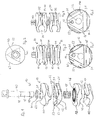
- Fig. 1 shows a perspective exploded view of a preferred first embodiment of a clamp 10 pursuant to the invention.
- the clamp 10 consists of a first clamping assembly 20 and a second clamping assembly 30 and a shaft 40 which is positioned through bores 21, 31 within the two clamp assemblies 20, 30 along the longitudinal axis of shaft 40.
- the shaft 40 is preferably a locking element adapted to allow closing the clamp assemblies 20 and 30.
- Shaft 40 enters a first jaw 11 through a washer 41.
- the shaft 40 comprises a proximal portion 42 and a reduced diameter portion 43 which is followed by a thread portion 49.
- the outer threaded portion 49 is adapted to be screwed into a complementary inner thread within the distal jaw 11 so that turning the head of the shaft 40 changes the longitudinal position of the shaft 40 against the lower jaw 11, which allows opening or closing the entire clamp 10 against the force of a spring 15 provided between the two clamp assemblies 20 and 30.
- Said spring 15 is preferably positioned in corresponding receptions in the jaws 12. Instead of a spring 15, provided around shaft 40, it is possible to provide a different spring means as Belleville washers or an elastic compressible solid or foam.
- the end portion of the thread 49 is destroyed through pressure to ensure that the shaft 40 cannot be removed from the clamping assemblies 20, 30 to maintain the clamp as one single piece.
- Each clamping assembly 20 or 30 comprises two opposing clamping jaws 11 and 12.
- jaws 11 and 12 are essentially similarly shaped on the sides facing each other beside a pin 13 which extends into a corresponding bore 14.
- This pin-bore connection which is oriented along the longitudinal axis of the clamping device is an anti-rotation device for jaws 11 and 12, so that these jaws 11, 12 cannot change their mutual angular orientation.
- the plane surface of jaw 11 facing the plane surface of jaw 12 is provided with three spacers 17 arranged in the corners of said surface.
- the spacers 17 have a mostly triangular form and a height to allow the function of a counter bearing as explained below. Additionally, the spacers 17 allow that the two plane surfaces of the jaws 11 and 12 are in a distance so that the free room between these surfaces can be cleaned.
- the jaws 11 and 12 are provided here with three grooves 51, 52 and 53.
- Grooves 51, 52 and 53 are all provided in a same plane perpendicular to the longitudinal axis of shaft 40. In that plane they are oriented perpendicular to the radial direction from the center of the bore 21 or 31. As such the grooves 51, 52 and 53 are parallel to outer side wall 61, 62 or 63 of each pair of jaws 11 and 12.
- the grooves 51, 52 and 53 are each formed as a rounded semi-spherical recess in section to provide receptions 71, 72 and 73 which accommodate cylindrical pins or rods 100 with a defined diameter (see Fig. 11 to 13 ), if the clamp is closed.
- the outer side walls 61, 62 or 63 can comprise an inclined sliding surface to allow an easier clipping of such pins or rods 100 into the corresponding reception.
- the grooves 51, 52, 53 are called to form rounded semi-spherical recesses in a section. This means that the recesses provided by the grooves 51, 52, 53 have a hollow cylindrical shape to accommodate rod-shaped elements.
- All three grooves 51, 52 and 53 have different sizes so that the corresponding receptions 71, 72 and 73 have three different sizes.
- each reception 71, 72 or 73 is adapted to accept a different fixation element, i.e. a rod, screw, pin or wire having a different diameter.
- One preferred embodiment of the first clamping assembly 20 has grooves to accept fixation elements having a diameter of 12 mm, 8 mm and 5 mm, respectively.
- a different embodiment may have a sequence of diameters of 8 mm, 6 mm and 4 mm, respectively.
- the second clamping assembly 30 also comprises two jaw portions 11 and 12 and these comprise three grooves 51, 52, 53. These grooves 51, 52, 53 also comprise a sequence of different sizes.
- the inner jaws portion 12 have an identical structure as have the outer jaws 11, especially in view of the anti-rotation device 44, the reception for a spring 15 as well as ribs 45 inside the grooves 51, 52, and 53.
- the first clamping assembly 20 may comprise a sequence of smaller sizes, e.g. 7 mm, 5 mm and 3 mm; or 6 mm, 5mm and 4 mm; and the second clamping assembly 30 may comprise a sequence of larger sizes, e.g. 13.5 mm, 12 mm and 10 mm. Different sizes are possible, usually for wires starting from 2 mm diameter until thicker rods with a diameter of 30 mm are used within such a clamp 10.
- Such a clamp 10 allows using one single versatile clamp, wherein the first clamping assembly 20 is used to fix a specific pin or screw or wire having a diameter for which one of the receptions 71, 72 or 73 is adapted. The user takes the clamp 10 and orients the first clamping assembly 20 into the correct alignment so that the pin or screw can be clipped into the corresponding reception.
- the clamp 10 can be clamped on a rod of an external fixator with the help of the second clamping assembly 30.
- Said second clamping assembly 30 can be oriented in a way so that the rod can be clipped into the corresponding reception. It is an advantage of the clamp 10 having two clamping assemblies 20 and 30 according to the invention, that a practitioner attaching such a clamp at a bone screw with one clamping assembly 20 and subsequently a rod of an external fixator to the other clamping assembly 30 can check the robustness of his external fixator, and if he finds that the rod he has used is not stiff enough, he simply opens the second clamping assembly 30, removes the thinner rod, turns the second clamping assembly 30 e.g.
- the second clamping assembly 30 is a traditional clamping assembly or even any other element known in the prior art with clamping elements.
- the object of a versatile clamping assembly is already achieved through one first clamping assembly 20, since it allows clamping one of three different sizes of screws, pins of wires through simple reorientation of the first clamping assembly 20.
- Fig. 2 shows a view from above on the clamp according to Fig. 1 . Since the embodiment of Fig. 1 comprises three grooves 51, 52 and 53, there are three side walls 61, 62 and 63, which provide, when looked from above as in Fig. 2 a triangular shape of each clamping assembly 20 or 30.
- Fig. 3 shows a first side view of the clamp of Fig. 1 and Fig. 4 shows a second different side view of the clamp 10 of Fig. 1 from a different direction.
- Identical reference signs are used for identical features within the same embodiment and are used for identical or similar features in further embodiments.
- first receptions 71 are identical in their size and allow reception of a large rod.
- third receptions 73 are small receptions, e.g. for a pin.
- second receptions 72 have an intermediate size. From Fig. 4 it can be seen that the depicted embodiment has a decreasing size sequence of the receptions 71, 72 and 73 in the upper first clamping assembly 20 in clockwise direction whereas the depicted embodiment has a decreasing size sequence of the receptions 71, 72 and 73 in the lower second clamping assembly 30 in counterclockwise direction.
- each jaw portion 11 or 12 of any clamping assembly 20, 30 comprises three differently sized grooves 51, 52 and 53, respectively.
- the longitudinal axes of these grooves 51, 52 and 53 are oriented in an angle of 60 degree one to another. However, these angles of 60 degree are not mandatory. It is only necessary that the total internal angle of the triangle provided by these three grooves 51, 52 and 53 is 180 degrees.
- the grooves are also in the same median plane which indicates that only one pin, screw or rod can usually be introduced in one of the grooves 51, 52 or 53 and such an introduction blocks the other empty grooves.
- the inner jaw portion 12 shown in Fig. 5 comprises ribs 45 which are oriented in the longitudinal direction of the grooves 51, 52 and 53.
- Each groove is provided with two lines of ribs 45, which are arranged one behind the other and thus can also be described to be a single line interrupted in the middle part.
- the angle between the largest groove 51 and the neighboring grooves can be less than 60 degree, so that the angle between the longitudinal axes of the grooves 52 and 53 is greater then 60 degrees.
- each jaw comprises four grooves joining in the corners in a - preferably - right angle. Then a sequence of four sizes of the receptions is possible as 12 mm, 8 mm, 6 mm and 4 mm.
- the form of such a clamping assembly 20 seen from above is a pentagon and each jaw comprises five grooves joining in the corners, preferably at an angle of around 108 degrees. Then a sequence of five sizes of the receptions is possible as 12 mm, 20 mm, 8 mm, 6 mm and 4 mm. Of course deviations from such a symmetrical polygon are possible.
- the spacers 17 and thus the counter bearings as well as the corners of the jaw planes are not symmetrically positioned in view of the central bore 21 of a jaw.
- the deviation from the symmetric form is smaller for the largest reception 71 and larger for the smallest reception 73.
- this is not problematic, since the largest reception 71 with the smallest deviation accepts the largest rod and thus the largest forces, wherein the largest deviation occurs for the smallest reception and the function of such a small reception resides in accepting a limited force.
- Fig. 7 shows a cross-section of the clamp according to Fig. 4 , wherein the clamp 10 is shown in a premounted state, i.e. the spring 15 is under tension.
- the upper jaw 11 of the first clamping assembly 20 is therefore pushing the rounded counter piece 41 against a flange of the head of shaft 40.
- the jaw 11 has around its bore 21 a rounded recess to accommodate the washer 41. This enables a pivoting movement of the upper jaw 11 against the axis of the shaft 40, since the shaft 40 comprises a reduced diameter portion 43 extending over the whole length of the jaws 11 and 12 in both assemblies. It is also possible that there is no play between shaft 40 and jaw 11; the bore 21 just allows the introduction of the shaft 40. Then jaw 11 and jaw 12 can only effect a translatory movement.
- the pin 13 of the upper jaw 11 is lodged in a room 16 in the bore 14. It is possible but not necessary that the pin 13 or the room 16 receives an elastic fitting piece allowing elastic movements of the pin within the room 16.
- the shaft 40 as part of a locking element is threaded into the lower jaw 11 of the second clamping assembly 30 and is further connected with a counter nut 46, which is fixedly lodged in shaft 40. Therefore the two clamp assemblies 20, 30 can be opened and closed through turning the head of shaft 40 and thus turning said shaft 40 with the blocking counter nut 46 in the jaw thread.
- shaft 40 and counter nut 46 can also be replaced by a single screw to be screwed into the lower jaw 11 of the second clamping assembly 30. Threading may be provided in the bore or the screw may exhibit self-tapping threading. Quite generally, a locking element may be provided which may be a lever locking element or a bayonet lock. Among these locking elements may also be supporting disks or toothed disks, which, for the sake of simplicity, are not shown in the drawings.
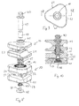
- Fig. 8 shows an exploded view of a second embodiment of the clamp of the present invention
- Fig. 9 shows a view from above on said clamp
- Fig. 10 shows a cross-section of said clamp along line X-X in Fig. 9 .
- the sequence of sizes for the first clamping assembly 20 is 13,5 mm, 8 mm and 5 mm. The choice of this sequence depends on the intended application (e.g. which limb is to be treated) of the external fixator set and follows the needs of the application.
- the clamping assemblies 20, 30 of said embodiment have a triangular form, as can be seen from Fig. 9 , having defined straight side walls 61, 62 and 63 and identically curved transitory portions.
- the first clamping assembly 20 comprises a sequence of larger sized receptions 71, 72, 73.
- the lower second clamping assembly 30 comprises a different sequence of smaller sized receptions 71, 72, 73.
- the corresponding grooves 51, 52 and 53 within the lower jaw 11 are not semi-spherical as with the clamp of Fig. 1 but are triangular grooves 51, 52, 53 having a bottom line 54.
- the corresponding groove portion in the opposite jaw 12 is a rounded groove, in Fig. 10 receiving the numeral 55, so that slightly different sizes of elements can be clamped. However, the sizes of the grooves 51, 52 and 53 are nevertheless different one from the other.
- the rounded grooves are intended to be used especially with carbon rods and allow high precision clamping under all circumstances, whereas the triangular grooves are more flexible. They usually provide two sizes with one groove, e.g. 4-5 mm, 5-6 mm and 7-8 mm for three grooves.
- Element 47 is a steel helicoil inserted into the aluminum jaw 11 to provide a better counter thread for the thread 49 of shaft 40.
- the end portion 49 of shaft 40 is hollow with an additional inner thread to accommodate the outer thread 58 of the counter nut 48.
- Fig. 11 shows a view from above of the clamp 10 of the present invention with two attached fixation elements 100 and 101.
- Fig. 12 shows a front view of the clamp according to Fig. 11; and
- Fig. 13 shows a view from the right.
- fixation elements shown here are small-sized rods.
- Fixation element 100 is introduced in the smallest size reception 73 of the first clamping assembly 20 leaving the middle-sized reception 72 and the large-size reception 71 empty. From Fig. 12 it can be seen that the introduction of rod 100 blocks the section of reception 72. From Fig. 13 it can be seen that the introduction of rod 100 also blocks the section of reception 73. Therefore a clamping assembly 20 is usable for one single rod or pin at the same time, here rod 100.
- the two clamping assemblies have an identical sequence of reception sizes, i.e. there are three sizes of receptions twice in the clamp 10.
- the sequence is not necessarily distributed according to size.
- One clamping assembly can have sizes 3 mm, 5 mm and 8 mm, whereas the complementary assembly has the sizes 4 mm, 6 mm and 10 mm, showing a mixed sequence.
- grooves 51, 52 and 53 are preferably provided in a distance from the center of the clamp 10 so that the rods, pins or screws which are to be inserted in the created receptions are flush with the side walls 61, 62 or 63 as it can be seen in Fig. 11 .
- the single clamping assemblies 20 or 30 can be combined in different ways. If a clamping assembly having round grooves is called a rod clamping assembly and a clamping assembly having triangular grooves is called a pin clamping assembly then several clamps having two single clamping assemblies 20 or 30 are possible, i.e. pin-pin, rod-pin or rod-rod.
- the clamp or articulation element according to the invention has at least two opposing first and second clamping jaws 11 and 12, providing one lateral open free space for laterally receiving a rod-shaped element 100.
- Said lateral open free space is formed through grooves and is also called reception.
- inserts i.e. a jacket element adapted to be inserted in one jaw of the clamp to modify the space available for the rod-shaped element.
- Such an insert can be built according to e.g. EP 1 661 523 and introduced into the receptions to have additional versatility.
- a triangular clamp 10 according to the invention comprises a clamping assembly 20 or 30 having two identical grooves within the three grooves. This is especially true, if according to a different embodiment, four, five or more grooves are provided.
- the four receptions may be: small, large, small, large; which allows the parallel introduction and fixation of two small pins or two large rods, since the square disposition do not hinder the simultaneous introduction of two pins or rods.
- the same is true, if five grooves/receptions are provided, since an angle of around 108 degrees, two out of the five receptions can be used.
- At least the lower jaw 11 of the second assembly 30 has a different color then the other jaws to indicate that there is a specific sequence of sizes. It is e.g. possible that said lower jaw is green, indicating that said clamping assembly 30 provides a sequence of larger receptions (13.5 mm, 10 mm, 8 mm) whereas the other clamping assembly 20 provide smaller receptions (e.g. 6 mm, 5 mm and 4 mm). It is also possible to provide the upper most jaw 11 of the first clamping assembly 20 with a different color, e.g. blue to indicate that said clamping assembly 20 provides the smaller receptions.
Landscapes
- Health & Medical Sciences (AREA)
- Orthopedic Medicine & Surgery (AREA)
- Engineering & Computer Science (AREA)
- General Engineering & Computer Science (AREA)
- Surgery (AREA)
- Life Sciences & Earth Sciences (AREA)
- Mechanical Engineering (AREA)
- Medical Informatics (AREA)
- Heart & Thoracic Surgery (AREA)
- Molecular Biology (AREA)
- Animal Behavior & Ethology (AREA)
- General Health & Medical Sciences (AREA)
- Public Health (AREA)
- Veterinary Medicine (AREA)
- Biomedical Technology (AREA)
- Nuclear Medicine, Radiotherapy & Molecular Imaging (AREA)
- Surgical Instruments (AREA)
Claims (14)
- Fixerungsklemme (10), insbesondere zur Verwendung in einem externen Fixationssystem zum Halten von benachbarten Knochenfragmenten mit Hilfe von Fixierelementen (100), aufweisend mindestens zwei Klemmanordnungen (20, 30), wobei jede der Klemmanordnungen (20, 30) zwei Backen (11, 12) hat und drei, vier oder fünf Aufnahmen (71, 72, 73) hat, wobei jede von ihnen geeignet ist, ein Fixierelement (100) entlang der Längsachse der Aufnahme aufzunehmen, wobei jede der Aufnahmen (71, 72, 73) durch sich auf jeder der beiden Backen (20, 30) befindende Nuten (51, 52, 53) gebildet wird, wobei die Längsachse der besagten Aufnahmen (71, 72, 73) ein Polygon aufspannen, dadurch gekennzeichnet, dass mindestens zwei Aufnahmen (71, 72, 73) eine unterschiedliche Durchmessergrösse aufweisen, wobei jede von ihnen geeignet ist, ein entsprechendes durchmesserangepasstes Fixierelement (100) aufzunehmen, und wobei jede Klemmanordnung (20, 30) eine dreieckige Form aufweist falls sie drei Aufnahmen (71, 72, 73) hat, eine quadratische Form aufweist falls sie vier Aufnahmen (71, 72, 73) hat, und eine Polygonform aufweist falls sie fünf Aufnahmen (71, 72, 73) hat.
- Fixierungsklemme (10) gemäss Anspruch 1, wobei jede Klemmanordnung (20, 30) drei Aufnahmen (71, 72, 73) aufweist, wobei das Polygon ein Dreieck ist, und wobei Längsachsen dieser Nuten (51, 52, 53) in einem Winkel von 60 Grad zueinander ausgerichtet sind.
- Fixierungsklemme (10) gemäss Anspruch 1, wobei jede Klemmanordnung (20, 30) drei Aufnahmen (71, 72, 73) aufweist, wobei das Polygon ein Dreieck ist, und wobei Längsachsen dieser Nuten (51, 52, 53) derart ausgerichtet sind, dass ein Winkel zwischen der grössten Nut (51) und den benachbarten Nuten (52, 53) weniger als 60 Grad ist und ein Winkel zwischen den Längsachsen der benachbarten Nuten (52, 53) grösser als 60 Grad ist.
- Fixierungsklemme (10) gemäss Anspruch 2 oder 3, wobei die Backen (11, 12) auf einander zugewandten Seiten neben einem auf einer Backe (11) angeordneten Stift (13) und einer auf der anderen Backe (12) angeordneten entsprechenden Ausnehmung (16) im Wesentlichen ähnlich ausgebildet sind, wobei sich der Stift (13) in eine entsprechende Ausnehmung (16) erstreckt wenn die Backen (11, 12) einander kontaktieren, wobei die Verbindung Stift (13)-Ausnehmung (16) entlang einer Längsachse der Fixierungsklemme (10) ausgerichtet ist und als eine Verdrehsicherung für die Backen (11, 12) wirkt, und wobei eine der ebenen Fläche der Backe (12) zugewandte ebene Fläche der Backe (11) über drei mehrheitlich dreieckförmige Abstandshalter (17) verfügt oder über zwei abgeflachte halbkugelförmige Abstandshalter (27) verfügt, welche in Ecken der besagten ebenen Fläche angeordnet sind.
- Fixierungsklemme (10) gemäss Anspruch 4, wobei der Stift (13) oder die Ausnehmung (16) ein elastisches Passstück aufnimmt, welches elastische Bewegungen des Stifts (13) innerhalb der Ausnehmung (16) erlaubt.
- Fixierungsklemme (10) gemäss einem der Ansprüche 1 bis 5, wobei mindestens eine untere Backe (11) der Backen (11, 12) einer zweiten Anordnung (30) der Anordnungen (20, 30) eine andere Farbe hat als die anderen Backen der Fixierungsklemme (10).
- Fixierungsklemme (10) gemäss Anspruch 1, wobei die zwei Klemmanordnungen (20, 30) eine identische Abfolge von Aufnahmegrössen haben.
- Fixierungsklemme (10) gemäss Anspruch 1, wobei jede Aufnahme (71, 72, 73) eine unterschiedliche Grösse hat.
- Fixierungsklemme (10) gemäss Anspruch 1, wobei besagte Klemmanordnung (20, 30) vier Aufnahmen aufweist und wobei das Polygon ein Viereck ist.
- Fixierungsklemme (10) gemäss Anspruch 9, wobei jede Aufnahme im Vergleich zu jeder benachbarten Aufnahme eine unterschiedliche Grösse hat, wobei wahlweise zwei gegenüberliegende Aufnahmen dieselbe Grösse haben.
- Fixierungsklemme (10) gemäss Anspruch 1, wobei besagte Klemmanordnung (20, 30) fünf Aufnahmen aufweist und wobei das Polygon ein Fünfeck ist.
- Fixierungsklemme (10) gemäss Anspruch 1, wobei die Nuten (51, 52, 53) die Form eines Teils eines Hohlzylinders haben oder dreieckig sind, und / oder wobei die Nuten (51, 52, 53) Längsrippen (45) aufweisen.
- Fixierungsklemme (10) gemäss den Ansprüchen 4 und 12, wobei jede Klemmanordnung (20, 30) einen Stift (13) aufweist, wobei der Stift (13) ein Verdrehsicherungsstift ist und sich von einer Backe (11) in eine komplementäre Ausnehmung (16) in der anderen Backe (12) erstreckt, und / oder wobei die Klemme (10) einen Verriegelungsschaft (40) aufweist, welcher sich durch die Klemmanordnungen (20, 30) erstreckt, um die Position der Klemmanordnungen (20, 30) in einer definierten Winkelposition zu blockieren.
- Fixierungsklemme (10) gemäss einem der Ansprüche 1 bis 13, wobei die Aufnahmen (71, 72, 73) in äusseren Seitenwänden (61, 62, 63) jeder Klemmanordnung (20, 30) in einer Weise vorgesehen sind, dass die Fläche eines entsprechenden Stabes (100,101), welcher von einem zentralen Verriegelungsschaft (40) weg zeigt wenn der entsprechende Stab in eine der Aufnahmen (71, 72, 73) eingeführt ist, bündig mit der entsprechenden Seitenwand (61, 62, 63) ist.
Priority Applications (1)
| Application Number | Priority Date | Filing Date | Title |
|---|---|---|---|
| EP13196005.6A EP2708196B1 (de) | 2009-05-15 | 2009-05-15 | Fixierungsklemme |
Applications Claiming Priority (2)
| Application Number | Priority Date | Filing Date | Title |
|---|---|---|---|
| EP13196005.6A EP2708196B1 (de) | 2009-05-15 | 2009-05-15 | Fixierungsklemme |
| EP09160445.4A EP2250968B1 (de) | 2009-05-15 | 2009-05-15 | Fixierungsklemme |
Related Parent Applications (1)
| Application Number | Title | Priority Date | Filing Date |
|---|---|---|---|
| EP09160445.4A Division EP2250968B1 (de) | 2009-05-15 | 2009-05-15 | Fixierungsklemme |
Publications (2)
| Publication Number | Publication Date |
|---|---|
| EP2708196A1 EP2708196A1 (de) | 2014-03-19 |
| EP2708196B1 true EP2708196B1 (de) | 2015-09-16 |
Family
ID=41139283
Family Applications (2)
| Application Number | Title | Priority Date | Filing Date |
|---|---|---|---|
| EP13196005.6A Active EP2708196B1 (de) | 2009-05-15 | 2009-05-15 | Fixierungsklemme |
| EP09160445.4A Active EP2250968B1 (de) | 2009-05-15 | 2009-05-15 | Fixierungsklemme |
Family Applications After (1)
| Application Number | Title | Priority Date | Filing Date |
|---|---|---|---|
| EP09160445.4A Active EP2250968B1 (de) | 2009-05-15 | 2009-05-15 | Fixierungsklemme |
Country Status (7)
| Country | Link |
|---|---|
| US (7) | US8827997B2 (de) |
| EP (2) | EP2708196B1 (de) |
| JP (2) | JP2010269143A (de) |
| CN (1) | CN101884562B (de) |
| AU (1) | AU2010201872B2 (de) |
| CA (1) | CA2703095C (de) |
| ES (2) | ES2451507T3 (de) |
Families Citing this family (62)
| Publication number | Priority date | Publication date | Assignee | Title |
|---|---|---|---|---|
| JP3201202B2 (ja) | 1995-01-12 | 2001-08-20 | ヤマハ株式会社 | 楽音信号合成装置 |
| US8029505B2 (en) * | 2005-08-25 | 2011-10-04 | Synthes Usa, Llc | External fixation system and method of use |
| ES2471948T3 (es) * | 2006-10-13 | 2014-06-27 | Stryker Trauma Sa | Prevención de reutilización de un dispositivo m�dico |
| ES2667759T3 (es) * | 2009-09-11 | 2018-05-14 | Stryker European Holdings I, Llc | Dispositivo de sujeción fácil de limpiar |
| US8858555B2 (en) | 2009-10-05 | 2014-10-14 | Stryker Trauma Sa | Dynamic external fixator and methods for use |
| IT1396145B1 (it) * | 2009-11-05 | 2012-11-16 | Citieffe Srl | Fissatore esterno polivalente. |
| ES2414532T3 (es) * | 2009-11-06 | 2013-07-19 | Orthofix S.R.L. | Pinza para dispositivo de fijación ortopédico externo |
| US11141196B2 (en) | 2010-08-11 | 2021-10-12 | Stryker European Operations Holdings Llc | External fixator system |
| US8945128B2 (en) | 2010-08-11 | 2015-02-03 | Stryker Trauma Sa | External fixator system |
| EP2417923B1 (de) | 2010-08-11 | 2013-11-13 | Stryker Trauma SA | Externes Befestigungssystem |
| US8585703B2 (en) * | 2010-12-09 | 2013-11-19 | Stryker Trauma Sa | Adjustment tool for external fixator |
| USD720853S1 (en) | 2010-12-14 | 2015-01-06 | Stryker Trauma Sa | Fixation clamp |
| EP2465455B1 (de) | 2010-12-14 | 2015-04-08 | Stryker Trauma SA | Fixierungsklemme |
| USD704840S1 (en) * | 2010-12-14 | 2014-05-13 | Stryker Trauma Sa | Hinge coupling |
| ES2540256T3 (es) * | 2010-12-14 | 2015-07-09 | Stryker Trauma Sa | Pinza de fijación |
| ES2541207T3 (es) | 2010-12-14 | 2015-07-16 | Stryker Trauma Sa | Pinza de fijación con rueda selectora |
| USD683461S1 (en) * | 2010-12-14 | 2013-05-28 | Stryker Trauma Sa | Hinge coupling |
| AU2011358377B2 (en) * | 2011-02-11 | 2014-11-13 | Orthofix S.R.L. | Clamp for temporary or definitive external orthopaedic fixation, and external fixation system comprising said clamp |
| JP6106662B2 (ja) * | 2011-05-17 | 2017-04-05 | ジンマー,インコーポレイティド | 起動機構及び蓄積ばねエネルギーを使用する外部固定クランプシステム |
| USD682426S1 (en) | 2011-06-14 | 2013-05-14 | Stryker Trauma Sa | Fixation clamp |
| USD663030S1 (en) | 2011-06-14 | 2012-07-03 | Styker Trauma SA | Fixation clamp |
| ITRM20110348A1 (it) * | 2011-07-04 | 2013-01-05 | Yordanova Radoslava | Fissatore universale per il fissaggio di uno o piu' elementi di forma allungata in particolare per la riduzione e la stabilizzazione delle fratture con l'uso della tecnica dei fili di kirschner |
| US9556972B2 (en) * | 2011-07-15 | 2017-01-31 | Commscope Technologies Llc | Adjustable cable manager |
| CN103957827B (zh) * | 2011-09-15 | 2017-03-01 | 斯泰克欧洲控股一有限责任公司 | 具有可变踝部位置的棒联接器 |
| ES2581533T3 (es) * | 2011-12-06 | 2016-09-06 | Stryker European Holdings I, Llc | Pinza de fijación |
| ITRM20120205A1 (it) * | 2012-05-10 | 2013-11-11 | Yordanova Radoslava | Fissatore universale per la giunzione di fili per la riduzione e la stabilizzazione delle fratture con l'uso della tecnica dei fili di kirschner |
| US8906021B1 (en) | 2012-08-20 | 2014-12-09 | Stryker Trauma Sa | Telescopic strut for an external fixator |
| US9101398B2 (en) | 2012-08-23 | 2015-08-11 | Stryker Trauma Sa | Bone transport external fixation frame |
| EP2967674B1 (de) * | 2013-03-15 | 2024-02-21 | Biomet C.V. | Polyaxiales gehäuse für einen fixateuer externe |
| US10194945B2 (en) | 2013-03-15 | 2019-02-05 | DePuy Synthes Products, Inc. | External fixation system with radio frequency shielding |
| US10610123B2 (en) | 2013-03-15 | 2020-04-07 | DePuy Synthes Products, Inc. | External fixation system with radio frequency shielding |
| US9408635B2 (en) * | 2013-03-15 | 2016-08-09 | Wright Medical Technology, Inc. | External fixation |
| ITMI20130407A1 (it) * | 2013-03-18 | 2014-09-19 | Orthofix Srl | Dispositivo di fissazione esterna |
| US9962188B2 (en) | 2013-10-29 | 2018-05-08 | Cardinal Health 247. Inc. | External fixation system and methods of use |
| US9445841B2 (en) * | 2014-12-10 | 2016-09-20 | Texas Scottish Rite Hospital For Children | Wire tensioner tip for use with wire fixation bolt |
| JP2018507762A (ja) * | 2015-02-06 | 2018-03-22 | チェン、ジChen, Ji | 高周波誘起された加熱を低減するために吸収材料を使用する外部固定器具 |
| US11266444B2 (en) | 2015-02-06 | 2022-03-08 | University Of Houston System | External fixation device with absorption material for reducing radiofrequency induced heat transfer and method thereof |
| US10531896B2 (en) * | 2015-08-10 | 2020-01-14 | Stryker European Holdings I, Llc | Distraction tube with wire clamp |
| US10682160B2 (en) | 2015-12-03 | 2020-06-16 | Globus Medical, Inc. | External fixator assembly |
| US9943337B2 (en) * | 2015-12-03 | 2018-04-17 | Globus Medical, Inc. | External fixator assembly |
| US10136919B2 (en) | 2015-12-03 | 2018-11-27 | Globus Medical, Inc. | External fixator assembly |
| US9872707B2 (en) | 2015-12-03 | 2018-01-23 | Globus Medical, Inc. | External fixator assembly |
| CN105943141B (zh) * | 2016-06-09 | 2018-07-10 | 苏州爱得科技发展股份有限公司 | 一种医用高分子骨外固定装置 |
| US10010350B2 (en) | 2016-06-14 | 2018-07-03 | Stryker European Holdings I, Llc | Gear mechanisms for fixation frame struts |
| US10874433B2 (en) | 2017-01-30 | 2020-12-29 | Stryker European Holdings I, Llc | Strut attachments for external fixation frame |
| US10568662B2 (en) * | 2017-10-12 | 2020-02-25 | The Orthopaedic Implant Company | Orthopedic clamping devices |
| US11034000B2 (en) * | 2017-10-27 | 2021-06-15 | John C. Molburg | Frame block clamp |
| US10945765B2 (en) | 2017-12-06 | 2021-03-16 | Austin Miller Trauma LLC | Fixation clamp with spacer |
| IT201800002749A1 (it) * | 2018-02-16 | 2019-08-16 | Orthofix Srl | Morsetto ad attacco rapido per sistemi di fissazione esterna |
| US11571243B2 (en) * | 2018-05-18 | 2023-02-07 | Beth Israel Deaconess Medical Center, Inc. | External fixation clamp and systems for medical procedures |
| USD1010122S1 (en) | 2019-05-17 | 2024-01-02 | Lifecell Corporation | External fixation clamp for medical procedures |
| USD957635S1 (en) | 2019-05-17 | 2022-07-12 | Beth Israel Deaconess Medical Center, Inc. | External medical fixation clamp |
| IT201900007314A1 (it) * | 2019-05-27 | 2020-11-27 | Orthofix Srl | Morsetto ad attacco rapido per sistemi di fissazione esterna |
| USD927294S1 (en) * | 2019-09-05 | 2021-08-10 | Mafi Ab | Fastening device |
| US11864798B2 (en) * | 2019-09-30 | 2024-01-09 | Gitlin LLC | Y-frame external bone fixator |
| US12514582B2 (en) * | 2020-02-19 | 2026-01-06 | DePuy Synthes Products, Inc. | Components for use in combination external fixation and negative pressure wound therapy system and methods of production and use thereof |
| CN111664147A (zh) * | 2020-06-10 | 2020-09-15 | 广东博智林机器人有限公司 | 一种抱夹装置、控制方法、电子设备及存储介质 |
| US11660122B2 (en) * | 2021-03-19 | 2023-05-30 | Infix, Inc. | Universal clamp apparatus for bone fixation device |
| FR3121343A1 (fr) * | 2021-03-31 | 2022-10-07 | J.P.P. Management | Pinces et kit pour structure de fixation externe orthopedique |
| EP4166102B1 (de) * | 2021-10-13 | 2026-03-04 | Hank Schiffers | Klemmvorrichtung für einen externen fixateur |
| US12484935B1 (en) * | 2024-05-09 | 2025-12-02 | Christopher D. Endara | Fixator rod coupler assembly |
| US12446923B1 (en) | 2024-06-05 | 2025-10-21 | Christopher D. Endara | Fixator distraction clamp assembly |
Family Cites Families (99)
| Publication number | Priority date | Publication date | Assignee | Title |
|---|---|---|---|---|
| US508687A (en) * | 1893-11-14 | Cleat for electric wiring | ||
| US24303A (en) * | 1859-06-07 | Improvement in harrows | ||
| DE518329C (de) | 1931-02-16 | Schanzenbach & Co G M B H G | Mehrfachanordnung von Schraubensicherungen, z. B. an Buchsenklemmen fuer elektrische Installationsapparate | |
| US566709A (en) * | 1896-08-25 | Bond-connector for rails | ||
| US693206A (en) * | 1901-05-06 | 1902-02-11 | Homer Wilson Wyckoff | Wire-connector. |
| US758910A (en) * | 1903-12-05 | 1904-05-03 | Harrison Woodmanse | Tightener for brace-rods. |
| US902040A (en) * | 1906-03-12 | 1908-10-27 | Homer W Wyckoff | Wire-connector. |
| US951095A (en) * | 1909-01-22 | 1910-03-01 | Felix S Senton | Wire-rope clamp. |
| US944850A (en) * | 1909-07-13 | 1909-12-28 | Samuel J Edmiston | Guy-wire clamp. |
| US1245197A (en) * | 1917-05-05 | 1917-11-06 | American Hoist & Derrick Co | Clip for wire-rope members. |
| US1950635A (en) * | 1930-06-05 | 1934-03-13 | Line Material Co | Connecter |
| US2313280A (en) * | 1941-04-21 | 1943-03-09 | American Diagrid Corp | Beam connecting unit |
| US2422332A (en) * | 1944-03-06 | 1947-06-17 | Stephen P Becker | Connector |
| US2475268A (en) * | 1946-06-11 | 1949-07-05 | Clarence R Wittle | Toolholder |
| CH271970A (de) * | 1948-06-21 | 1950-11-30 | Kobler & Co | Baukasten. |
| US2658776A (en) * | 1950-03-14 | 1953-11-10 | Burr C Wilcox | Structural rod joint |
| US2696996A (en) * | 1952-07-14 | 1954-12-14 | Armin E Engelhardt | Clamping device |
| US2709318A (en) * | 1952-11-24 | 1955-05-31 | W R Benjamin Co | Toy construction elements |
| US2715537A (en) * | 1952-12-04 | 1955-08-16 | Richard W Hofheimer | Coupling or connecting device |
| US2745181A (en) * | 1953-01-27 | 1956-05-15 | John F Czerniewicz | Drafting compass |
| US4597690A (en) * | 1979-11-23 | 1986-07-01 | Girard Development Incorporated | Tube clamps |
| US4597140A (en) * | 1983-08-08 | 1986-07-01 | Girard Development Incorporated | Tube clamp |
| IL69888A0 (en) * | 1983-10-03 | 1984-01-31 | Avmedica Ltd | Unilateral external fixation system for small bones |
| CH657899A5 (en) * | 1984-02-29 | 1986-09-30 | Collombin Andre M | Device for assembling elements |
| US4589236A (en) * | 1984-06-05 | 1986-05-20 | Mcallister Jack G | Geometric frame assembly |
| FR2572929B1 (fr) * | 1984-11-15 | 1987-09-04 | Jawish Roger | Fixateur externe des os et des articulations |
| US4653481A (en) * | 1985-07-24 | 1987-03-31 | Howland Robert S | Advanced spine fixation system and method |
| US4620533A (en) * | 1985-09-16 | 1986-11-04 | Pfizer Hospital Products Group Inc. | External bone fixation apparatus |
| US4730608A (en) * | 1986-03-05 | 1988-03-15 | Schlein Allen P | External bone-anchoring fixator |
| WO1989011254A1 (fr) * | 1988-05-26 | 1989-11-30 | Vsesojuzny Kurgansky Nauchny Tsentr ''vosstanovite | Appareil de compression-traction pour osteosynthese |
| JPH0516631Y2 (de) * | 1988-04-05 | 1993-04-30 | ||
| JPH03501343A (ja) * | 1988-07-26 | 1991-03-28 | フセソユズニ クルガンスキ ナウチニ ツェントル “ボススタノビテルナヤ トラフマトロギア イ オルトペディア” | 短い管状骨接合の伸延装置 |
| US4982546A (en) * | 1988-11-01 | 1991-01-08 | Interlock Structures International, Inc. | Space frame node |
| US5451226A (en) * | 1989-03-06 | 1995-09-19 | Pfeil; Joachim | Unilateral, extensible, external tensioning device for treating bone diseases |
| US5127759A (en) * | 1989-04-20 | 1992-07-07 | Orbom Eric W | Continuous connector |
| US4958793A (en) * | 1989-05-01 | 1990-09-25 | Hess Norman B | Stanchion |
| US5030220A (en) * | 1990-03-29 | 1991-07-09 | Advanced Spine Fixation Systems Incorporated | Spine fixation system |
| DE9101690U1 (de) * | 1991-02-14 | 1991-05-08 | Expo Products Trading Sulser & Cie, Wetzikon | Lampenfuß |
| US5810817A (en) * | 1992-06-19 | 1998-09-22 | Roussouly; Pierre | Spinal therapy apparatus |
| US5304177A (en) * | 1992-06-26 | 1994-04-19 | Dietmar Pennig | Auxiliary device for osteosynthesis |
| US5498264A (en) * | 1992-07-21 | 1996-03-12 | Synthes (U.S.A.) | Clamp connection for connecting two construction components for a setting device, particularly an osteosynthetic setting device |
| US5342361A (en) * | 1993-01-14 | 1994-08-30 | Yuan Hansen A | Dual tier spinal locking and retrieving system and instrumentation for administering such system percutaneously |
| US5624440A (en) * | 1996-01-11 | 1997-04-29 | Huebner; Randall J. | Compact small bone fixator |
| DE59406392D1 (de) * | 1993-02-18 | 1998-08-13 | Endocare Ag | Vorrichtung zur verlängerung von knochen |
| US5601554A (en) * | 1993-03-04 | 1997-02-11 | Advanced Spine Fixation Systems, Inc. | Branch connector for spinal fixation systems |
| US5451225A (en) * | 1993-06-10 | 1995-09-19 | Texas Scottish Rite Hospital For Crippled Children | Fastener for external fixation device wires and pins |
| FR2718945B1 (fr) * | 1994-04-25 | 1996-07-05 | Soprane Sa | Dispositif de retenue d'une tige de liaison d'un fixateur de rachis sur une vis pédiculaire. |
| IT1268282B1 (it) * | 1994-08-23 | 1997-02-27 | Orthofix Srl | Fissatore trocanterico esterno |
| CH690293A5 (fr) | 1994-09-06 | 2000-07-14 | Jaquet Orthopedie | Articulation pour composants d'un fixateur externe. |
| US5501544A (en) * | 1994-11-10 | 1996-03-26 | Nolu Plastics, Inc. | Three-piece clamping assembly |
| US5961515A (en) * | 1995-03-01 | 1999-10-05 | Smith & Nephew, Inc. | External skeletal fixation system |
| US5662650A (en) * | 1995-05-12 | 1997-09-02 | Electro-Biology, Inc. | Method and apparatus for external fixation of large bones |
| IT1278856B1 (it) * | 1995-09-19 | 1997-11-28 | Orthofix Srl | Accessorio per fissatore esterno |
| US5897555A (en) * | 1997-05-15 | 1999-04-27 | Wright Medical Technology, Inc. | External fixation system and method |
| EP0838196A3 (de) * | 1997-11-30 | 1998-07-01 | Daniel Spitzer | Klemmverbindung für medizinische Geräte und Apparate |
| DE19813568C1 (de) * | 1998-03-27 | 1999-12-09 | Bosch Gmbh Robert | Vorrichtung zur Befestigung von Elementen an einem aus Drähten bestehenden Gitter |
| DE69830150T2 (de) * | 1998-06-09 | 2006-02-23 | Husson International S.A. | Verbindungsknoten |
| US6059784A (en) * | 1998-10-08 | 2000-05-09 | The United States Of America As Represented By The Administrator Of The National Aeronautics And Space Administration | Capacitive extensometer particularly suited for measuring in vivo bone strain |
| FR2787697B1 (fr) * | 1998-12-29 | 2001-06-15 | France Etat | Dispositif orthopedique monolateral de fixation externe pour l'immobilisation d'un os fracture |
| US6378265B1 (en) * | 1999-03-01 | 2002-04-30 | Matias Konstandt | Space frame construction assembly |
| US6277119B1 (en) * | 1999-10-21 | 2001-08-21 | Electro-Biology, Inc. | External fixation system |
| US6616664B2 (en) * | 1999-10-21 | 2003-09-09 | Ebi L.P. | Clamp assembly for an external fixation system |
| GB2367695B (en) * | 2000-09-27 | 2004-09-08 | Alan Dick & Company Ltd | Cable clamp |
| US6565564B2 (en) * | 2000-12-14 | 2003-05-20 | Synthes U.S.A. | Multi-pin clamp and rod attachment |
| US7004943B2 (en) * | 2002-02-04 | 2006-02-28 | Smith & Nephew, Inc. | Devices, systems, and methods for placing and positioning fixation elements in external fixation systems |
| US20030187432A1 (en) * | 2002-03-28 | 2003-10-02 | Johnson Tab C. | External fixation system |
| JP2003325058A (ja) | 2002-05-14 | 2003-11-18 | Kazuhiro Kurokawa | 支柱留具 |
| DE10246418A1 (de) * | 2002-10-04 | 2004-04-15 | Mtm Medizintechnik Mauk Gmbh | Verbindung von mindestens zwei einander kreuzenden Stäben |
| US20040073212A1 (en) * | 2002-10-15 | 2004-04-15 | Kim Jung Jae | Extracorporeal fixing device for a bone fracture |
| US7608074B2 (en) * | 2003-01-10 | 2009-10-27 | Smith & Nephew, Inc. | External fixation apparatus and method |
| EP1522266A1 (de) * | 2003-10-06 | 2005-04-13 | Stryker Trauma SA | Äusserliche Befestigungsvorrichtung |
| US7083622B2 (en) * | 2003-11-10 | 2006-08-01 | Simonson Peter M | Artificial facet joint and method |
| US8236028B2 (en) * | 2004-03-31 | 2012-08-07 | Depuy Spine Sarl | Spinal rod connector |
| DE502004009456D1 (de) * | 2004-08-20 | 2009-06-18 | Stryker Trauma Sa | Klemmelement und Gelenkelement |
| ATE375760T1 (de) | 2004-08-20 | 2007-11-15 | Stryker Trauma Sa | Klemmelement zum klemmen von mehreren stabförmigen elementen |
| DE502004006788D1 (de) * | 2004-11-30 | 2008-05-21 | Stryker Trauma Sa | Einsatz für ein Klemmelement, Klemmelement mit einem solchen Einsatz und daraus gebildete Gelenkverbindung |
| DE502005005095D1 (de) * | 2005-02-09 | 2008-10-02 | Stryker Trauma Sa | Einsatz für ein Klemmelement, Klemmelement mit einem solchen Einsatz und daraus gebildete Gelenkverbindung |
| US20060235383A1 (en) * | 2005-03-07 | 2006-10-19 | Shane Hollawell | External fixator |
| US7588571B2 (en) * | 2005-03-18 | 2009-09-15 | Ron Anthon Olsen | Adjustable splint for osteosynthesis with modular joint |
| DE202005005444U1 (de) * | 2005-04-01 | 2005-06-02 | Tantum Ag | Fixationseinrichtung zum stabilen Verbinden wenigstens zweier Knochenteile eines gebrochenen Knochens sowie Fixationselement und Bausatz |
| US7722609B2 (en) * | 2005-04-25 | 2010-05-25 | Synthes Usa, Llc | Outrigger with locking mechanism |
| US8758343B2 (en) * | 2005-04-27 | 2014-06-24 | DePuy Synthes Products, LLC | Bone fixation apparatus |
| US8523858B2 (en) * | 2005-06-21 | 2013-09-03 | DePuy Synthes Products, LLC | Adjustable fixation clamp and method |
| US20070038217A1 (en) * | 2005-08-09 | 2007-02-15 | Brown Daniel G | Orthopaedic fixation clamp and method |
| ES2246744B1 (es) * | 2005-10-11 | 2006-12-01 | Implantvet, S.L. | Articulacion para la solidarizacion mutua entre barras y/o agujas en un dispositivo de fijacion externa para la reduccion de fracturas oseas. |
| EP1820461B1 (de) * | 2006-02-21 | 2009-08-05 | Stryker Trauma SA | Klemm- und Gelenkelement |
| US20080016789A1 (en) * | 2006-07-18 | 2008-01-24 | Boots Alfred H | Spherical hub for modular structure system |
| ES2471948T3 (es) * | 2006-10-13 | 2014-06-27 | Stryker Trauma Sa | Prevención de reutilización de un dispositivo m�dico |
| US8277448B2 (en) * | 2007-03-07 | 2012-10-02 | Wright Medical Technology, Inc. | External fixation |
| US8147491B2 (en) * | 2007-06-27 | 2012-04-03 | Vilex In Tennessee, Inc. | Multi-angle clamp |
| CH702239B1 (de) * | 2008-06-17 | 2011-05-31 | Kai-Uwe Lorenz | Vorrichtung zur externen Fixierung von Knochenbrüchen. |
| US8187274B2 (en) * | 2008-06-30 | 2012-05-29 | Depuy Products, Inc. | External fixator |
| IT1391222B1 (it) * | 2008-09-11 | 2011-12-01 | Orthofix Srl | Dispositivo ortopedico da associare all'esterno di un osso |
| US8998961B1 (en) * | 2009-02-26 | 2015-04-07 | Lanx, Inc. | Spinal rod connector and methods |
| ES2667759T3 (es) * | 2009-09-11 | 2018-05-14 | Stryker European Holdings I, Llc | Dispositivo de sujeción fácil de limpiar |
| ES2414532T3 (es) * | 2009-11-06 | 2013-07-19 | Orthofix S.R.L. | Pinza para dispositivo de fijación ortopédico externo |
| JP5552705B2 (ja) * | 2010-07-01 | 2014-07-16 | ジンマー,インコーポレイティド | 多重ロック式外部固定クランプ |
| CN103957827B (zh) * | 2011-09-15 | 2017-03-01 | 斯泰克欧洲控股一有限责任公司 | 具有可变踝部位置的棒联接器 |
| EP3086725B1 (de) * | 2013-12-24 | 2018-05-23 | Akeso AG | Externer fixateur |
-
2009
- 2009-05-15 EP EP13196005.6A patent/EP2708196B1/de active Active
- 2009-05-15 ES ES09160445.4T patent/ES2451507T3/es active Active
- 2009-05-15 EP EP09160445.4A patent/EP2250968B1/de active Active
- 2009-05-15 ES ES13196005.6T patent/ES2555582T3/es active Active
-
2010
- 2010-05-04 CA CA2703095A patent/CA2703095C/en active Active
- 2010-05-07 AU AU2010201872A patent/AU2010201872B2/en active Active
- 2010-05-14 US US12/780,231 patent/US8827997B2/en active Active
- 2010-05-14 JP JP2010112205A patent/JP2010269143A/ja active Pending
- 2010-05-14 CN CN201010180484.4A patent/CN101884562B/zh active Active
-
2014
- 2014-07-07 US US14/324,507 patent/US9155562B2/en active Active
- 2014-09-25 JP JP2014194594A patent/JP5919352B2/ja active Active
-
2015
- 2015-07-22 US US14/805,925 patent/US9517086B2/en active Active
-
2016
- 2016-11-10 US US15/348,232 patent/US10117677B2/en active Active
-
2018
- 2018-10-05 US US16/152,523 patent/US10932821B2/en active Active
-
2021
- 2021-01-27 US US17/159,931 patent/US12161365B2/en active Active
-
2024
- 2024-11-14 US US18/948,004 patent/US20250143751A1/en active Pending
Also Published As
| Publication number | Publication date |
|---|---|
| EP2250968B1 (de) | 2013-12-11 |
| US12161365B2 (en) | 2024-12-10 |
| US20190029726A1 (en) | 2019-01-31 |
| CA2703095C (en) | 2016-08-09 |
| US20250143751A1 (en) | 2025-05-08 |
| CA2703095A1 (en) | 2010-11-15 |
| US20150320446A1 (en) | 2015-11-12 |
| ES2451507T3 (es) | 2014-03-27 |
| US9155562B2 (en) | 2015-10-13 |
| EP2708196A1 (de) | 2014-03-19 |
| ES2451507T8 (es) | 2014-04-09 |
| US20210145482A1 (en) | 2021-05-20 |
| US10932821B2 (en) | 2021-03-02 |
| JP5919352B2 (ja) | 2016-05-18 |
| US20140324045A1 (en) | 2014-10-30 |
| EP2250968A1 (de) | 2010-11-17 |
| CN101884562A (zh) | 2010-11-17 |
| US9517086B2 (en) | 2016-12-13 |
| AU2010201872B2 (en) | 2015-01-29 |
| AU2010201872A1 (en) | 2010-12-02 |
| ES2555582T3 (es) | 2016-01-05 |
| JP2010269143A (ja) | 2010-12-02 |
| US20100298827A1 (en) | 2010-11-25 |
| CN101884562B (zh) | 2014-01-22 |
| US10117677B2 (en) | 2018-11-06 |
| US20170056071A1 (en) | 2017-03-02 |
| US8827997B2 (en) | 2014-09-09 |
| JP2015042261A (ja) | 2015-03-05 |
Similar Documents
| Publication | Publication Date | Title |
|---|---|---|
| US12161365B2 (en) | Fixation clamp | |
| EP2294995B1 (de) | Leicht zu reinigende Klemmvorrichtung | |
| EP2465453B1 (de) | Fixierungsklemme | |
| EP2294994B1 (de) | Externe Befestigungskomponente | |
| EP2465455B1 (de) | Fixierungsklemme | |
| EP2465454A1 (de) | Fixierungsklemme mit Einstellrad | |
| EP2601900B1 (de) | Fixierungsklemme | |
| JP2008245730A (ja) | 創外固定器 |
Legal Events
| Date | Code | Title | Description |
|---|---|---|---|
| PUAI | Public reference made under article 153(3) epc to a published international application that has entered the european phase |
Free format text: ORIGINAL CODE: 0009012 |
|
| AC | Divisional application: reference to earlier application |
Ref document number: 2250968 Country of ref document: EP Kind code of ref document: P |
|
| AK | Designated contracting states |
Kind code of ref document: A1 Designated state(s): AT BE BG CH CY CZ DE DK EE ES FI FR GB GR HR HU IE IS IT LI LT LU LV MC MK MT NL NO PL PT RO SE SI SK TR |
|
| 17P | Request for examination filed |
Effective date: 20140911 |
|
| RBV | Designated contracting states (corrected) |
Designated state(s): AT BE BG CH CY CZ DE DK EE ES FI FR GB GR HR HU IE IS IT LI LT LU LV MC MK MT NL NO PL PT RO SE SI SK TR |
|
| GRAP | Despatch of communication of intention to grant a patent |
Free format text: ORIGINAL CODE: EPIDOSNIGR1 |
|
| RIC1 | Information provided on ipc code assigned before grant |
Ipc: F16B 7/04 20060101ALI20150506BHEP Ipc: A61B 17/64 20060101AFI20150506BHEP |
|
| INTG | Intention to grant announced |
Effective date: 20150603 |
|
| GRAS | Grant fee paid |
Free format text: ORIGINAL CODE: EPIDOSNIGR3 |
|
| GRAA | (expected) grant |
Free format text: ORIGINAL CODE: 0009210 |
|
| AC | Divisional application: reference to earlier application |
Ref document number: 2250968 Country of ref document: EP Kind code of ref document: P |
|
| AK | Designated contracting states |
Kind code of ref document: B1 Designated state(s): AT BE BG CH CY CZ DE DK EE ES FI FR GB GR HR HU IE IS IT LI LT LU LV MC MK MT NL NO PL PT RO SE SI SK TR |
|
| REG | Reference to a national code |
Ref country code: GB Ref legal event code: FG4D |
|
| REG | Reference to a national code |
Ref country code: CH Ref legal event code: EP |
|
| REG | Reference to a national code |
Ref country code: IE Ref legal event code: FG4D |
|
| REG | Reference to a national code |
Ref country code: AT Ref legal event code: REF Ref document number: 749151 Country of ref document: AT Kind code of ref document: T Effective date: 20151015 |
|
| REG | Reference to a national code |
Ref country code: DE Ref legal event code: R096 Ref document number: 602009033764 Country of ref document: DE |
|
| REG | Reference to a national code |
Ref country code: CH Ref legal event code: NV Representative=s name: ISLER AND PEDRAZZINI AG, CH |
|
| REG | Reference to a national code |
Ref country code: ES Ref legal event code: FG2A Ref document number: 2555582 Country of ref document: ES Kind code of ref document: T3 Effective date: 20160105 |
|
| REG | Reference to a national code |
Ref country code: NL Ref legal event code: MP Effective date: 20150916 |
|
| PG25 | Lapsed in a contracting state [announced via postgrant information from national office to epo] |
Ref country code: GR Free format text: LAPSE BECAUSE OF FAILURE TO SUBMIT A TRANSLATION OF THE DESCRIPTION OR TO PAY THE FEE WITHIN THE PRESCRIBED TIME-LIMIT Effective date: 20151217 Ref country code: LV Free format text: LAPSE BECAUSE OF FAILURE TO SUBMIT A TRANSLATION OF THE DESCRIPTION OR TO PAY THE FEE WITHIN THE PRESCRIBED TIME-LIMIT Effective date: 20150916 Ref country code: FI Free format text: LAPSE BECAUSE OF FAILURE TO SUBMIT A TRANSLATION OF THE DESCRIPTION OR TO PAY THE FEE WITHIN THE PRESCRIBED TIME-LIMIT Effective date: 20150916 Ref country code: LT Free format text: LAPSE BECAUSE OF FAILURE TO SUBMIT A TRANSLATION OF THE DESCRIPTION OR TO PAY THE FEE WITHIN THE PRESCRIBED TIME-LIMIT Effective date: 20150916 Ref country code: NO Free format text: LAPSE BECAUSE OF FAILURE TO SUBMIT A TRANSLATION OF THE DESCRIPTION OR TO PAY THE FEE WITHIN THE PRESCRIBED TIME-LIMIT Effective date: 20151216 |
|
| REG | Reference to a national code |
Ref country code: LT Ref legal event code: MG4D |
|
| REG | Reference to a national code |
Ref country code: AT Ref legal event code: MK05 Ref document number: 749151 Country of ref document: AT Kind code of ref document: T Effective date: 20150916 |
|
| PG25 | Lapsed in a contracting state [announced via postgrant information from national office to epo] |
Ref country code: HR Free format text: LAPSE BECAUSE OF FAILURE TO SUBMIT A TRANSLATION OF THE DESCRIPTION OR TO PAY THE FEE WITHIN THE PRESCRIBED TIME-LIMIT Effective date: 20150916 Ref country code: SE Free format text: LAPSE BECAUSE OF FAILURE TO SUBMIT A TRANSLATION OF THE DESCRIPTION OR TO PAY THE FEE WITHIN THE PRESCRIBED TIME-LIMIT Effective date: 20150916 |
|
| PG25 | Lapsed in a contracting state [announced via postgrant information from national office to epo] |
Ref country code: NL Free format text: LAPSE BECAUSE OF FAILURE TO SUBMIT A TRANSLATION OF THE DESCRIPTION OR TO PAY THE FEE WITHIN THE PRESCRIBED TIME-LIMIT Effective date: 20150916 |
|
| REG | Reference to a national code |
Ref country code: FR Ref legal event code: PLFP Year of fee payment: 8 |
|
| REG | Reference to a national code |
Ref country code: CH Ref legal event code: PUE Owner name: STRYKER EUROPEAN HOLDINGS I, LLC, US Free format text: FORMER OWNER: STRYKER EUROPEAN HOLDINGS V, LLC, US Ref country code: CH Ref legal event code: PUE Owner name: STRYKER EUROPEAN HOLDINGS V, LLC, US Free format text: FORMER OWNER: STRYKER TRAUMA SA, CH |
|
| PG25 | Lapsed in a contracting state [announced via postgrant information from national office to epo] |
Ref country code: CZ Free format text: LAPSE BECAUSE OF FAILURE TO SUBMIT A TRANSLATION OF THE DESCRIPTION OR TO PAY THE FEE WITHIN THE PRESCRIBED TIME-LIMIT Effective date: 20150916 Ref country code: EE Free format text: LAPSE BECAUSE OF FAILURE TO SUBMIT A TRANSLATION OF THE DESCRIPTION OR TO PAY THE FEE WITHIN THE PRESCRIBED TIME-LIMIT Effective date: 20150916 Ref country code: SK Free format text: LAPSE BECAUSE OF FAILURE TO SUBMIT A TRANSLATION OF THE DESCRIPTION OR TO PAY THE FEE WITHIN THE PRESCRIBED TIME-LIMIT Effective date: 20150916 Ref country code: IS Free format text: LAPSE BECAUSE OF FAILURE TO SUBMIT A TRANSLATION OF THE DESCRIPTION OR TO PAY THE FEE WITHIN THE PRESCRIBED TIME-LIMIT Effective date: 20160116 |
|
| PG25 | Lapsed in a contracting state [announced via postgrant information from national office to epo] |
Ref country code: RO Free format text: LAPSE BECAUSE OF FAILURE TO SUBMIT A TRANSLATION OF THE DESCRIPTION OR TO PAY THE FEE WITHIN THE PRESCRIBED TIME-LIMIT Effective date: 20150916 Ref country code: PL Free format text: LAPSE BECAUSE OF FAILURE TO SUBMIT A TRANSLATION OF THE DESCRIPTION OR TO PAY THE FEE WITHIN THE PRESCRIBED TIME-LIMIT Effective date: 20150916 Ref country code: AT Free format text: LAPSE BECAUSE OF FAILURE TO SUBMIT A TRANSLATION OF THE DESCRIPTION OR TO PAY THE FEE WITHIN THE PRESCRIBED TIME-LIMIT Effective date: 20150916 Ref country code: PT Free format text: LAPSE BECAUSE OF FAILURE TO SUBMIT A TRANSLATION OF THE DESCRIPTION OR TO PAY THE FEE WITHIN THE PRESCRIBED TIME-LIMIT Effective date: 20160118 |
|
| REG | Reference to a national code |
Ref country code: DE Ref legal event code: R097 Ref document number: 602009033764 Country of ref document: DE |
|
| REG | Reference to a national code |
Ref country code: DE Ref legal event code: R081 Ref document number: 602009033764 Country of ref document: DE Owner name: STRYKER EUROPEAN OPERATIONS HOLDINGS LLC, KALA, US Free format text: FORMER OWNER: STRYKER EUROPEAN HOLDINGS V, LLC (N.D. GES. D. STAATES DELAWARE), KALAMAZOO, MICH., US Ref country code: DE Ref legal event code: R081 Ref document number: 602009033764 Country of ref document: DE Owner name: STRYKER EUROPEAN OPERATIONS HOLDINGS LLC, KALA, US Free format text: FORMER OWNER: STRYKER TRAUMA SA, SELZACH, CH Ref country code: DE Ref legal event code: R082 Ref document number: 602009033764 Country of ref document: DE Representative=s name: MAIWALD PATENTANWALTSGESELLSCHAFT MBH, DE Ref country code: DE Ref legal event code: R081 Ref document number: 602009033764 Country of ref document: DE Owner name: STRYKER EUROPEAN HOLDINGS I, LLC (N.D. GES. D., US Free format text: FORMER OWNER: STRYKER TRAUMA SA, SELZACH, CH Ref country code: DE Ref legal event code: R081 Ref document number: 602009033764 Country of ref document: DE Owner name: STRYKER EUROPEAN HOLDINGS I, LLC (N.D. GES. D., US Free format text: FORMER OWNER: STRYKER EUROPEAN HOLDINGS V, LLC (N.D. GES. D. STAATES DELAWARE), KALAMAZOO, MICH., US Ref country code: DE Ref legal event code: R082 Ref document number: 602009033764 Country of ref document: DE Representative=s name: MAIWALD PATENTANWALTS- UND RECHTSANWALTSGESELL, DE |
|
| PLBE | No opposition filed within time limit |
Free format text: ORIGINAL CODE: 0009261 |
|
| STAA | Information on the status of an ep patent application or granted ep patent |
Free format text: STATUS: NO OPPOSITION FILED WITHIN TIME LIMIT |
|
| 26N | No opposition filed |
Effective date: 20160617 |
|
| PG25 | Lapsed in a contracting state [announced via postgrant information from national office to epo] |
Ref country code: BE Free format text: LAPSE BECAUSE OF NON-PAYMENT OF DUE FEES Effective date: 20160531 Ref country code: DK Free format text: LAPSE BECAUSE OF FAILURE TO SUBMIT A TRANSLATION OF THE DESCRIPTION OR TO PAY THE FEE WITHIN THE PRESCRIBED TIME-LIMIT Effective date: 20150916 |
|
| REG | Reference to a national code |
Ref country code: FR Ref legal event code: TP Owner name: STRYKER EUROPEAN HOLDINGS I, LLC, US Effective date: 20161003 |
|
| REG | Reference to a national code |
Ref country code: GB Ref legal event code: 732E Free format text: REGISTERED BETWEEN 20161013 AND 20161019 |
|
| REG | Reference to a national code |
Ref country code: ES Ref legal event code: PC2A Owner name: STRYKER EUROPEAN HOLDINGS I, LLC Effective date: 20161111 |
|
| PG25 | Lapsed in a contracting state [announced via postgrant information from national office to epo] |
Ref country code: SI Free format text: LAPSE BECAUSE OF FAILURE TO SUBMIT A TRANSLATION OF THE DESCRIPTION OR TO PAY THE FEE WITHIN THE PRESCRIBED TIME-LIMIT Effective date: 20150916 |
|
| PG25 | Lapsed in a contracting state [announced via postgrant information from national office to epo] |
Ref country code: LU Free format text: LAPSE BECAUSE OF FAILURE TO SUBMIT A TRANSLATION OF THE DESCRIPTION OR TO PAY THE FEE WITHIN THE PRESCRIBED TIME-LIMIT Effective date: 20160515 Ref country code: BE Free format text: LAPSE BECAUSE OF FAILURE TO SUBMIT A TRANSLATION OF THE DESCRIPTION OR TO PAY THE FEE WITHIN THE PRESCRIBED TIME-LIMIT Effective date: 20150916 |
|
| REG | Reference to a national code |
Ref country code: IE Ref legal event code: MM4A |
|
| REG | Reference to a national code |
Ref country code: FR Ref legal event code: PLFP Year of fee payment: 9 |
|
| PG25 | Lapsed in a contracting state [announced via postgrant information from national office to epo] |
Ref country code: IE Free format text: LAPSE BECAUSE OF NON-PAYMENT OF DUE FEES Effective date: 20160515 |
|
| REG | Reference to a national code |
Ref country code: FR Ref legal event code: PLFP Year of fee payment: 10 |
|
| PG25 | Lapsed in a contracting state [announced via postgrant information from national office to epo] |
Ref country code: HU Free format text: LAPSE BECAUSE OF FAILURE TO SUBMIT A TRANSLATION OF THE DESCRIPTION OR TO PAY THE FEE WITHIN THE PRESCRIBED TIME-LIMIT; INVALID AB INITIO Effective date: 20090515 Ref country code: CY Free format text: LAPSE BECAUSE OF FAILURE TO SUBMIT A TRANSLATION OF THE DESCRIPTION OR TO PAY THE FEE WITHIN THE PRESCRIBED TIME-LIMIT Effective date: 20150916 |
|
| PG25 | Lapsed in a contracting state [announced via postgrant information from national office to epo] |
Ref country code: MC Free format text: LAPSE BECAUSE OF FAILURE TO SUBMIT A TRANSLATION OF THE DESCRIPTION OR TO PAY THE FEE WITHIN THE PRESCRIBED TIME-LIMIT Effective date: 20150916 Ref country code: TR Free format text: LAPSE BECAUSE OF FAILURE TO SUBMIT A TRANSLATION OF THE DESCRIPTION OR TO PAY THE FEE WITHIN THE PRESCRIBED TIME-LIMIT Effective date: 20150916 Ref country code: MK Free format text: LAPSE BECAUSE OF FAILURE TO SUBMIT A TRANSLATION OF THE DESCRIPTION OR TO PAY THE FEE WITHIN THE PRESCRIBED TIME-LIMIT Effective date: 20150916 Ref country code: MT Free format text: LAPSE BECAUSE OF NON-PAYMENT OF DUE FEES Effective date: 20160531 |
|
| PG25 | Lapsed in a contracting state [announced via postgrant information from national office to epo] |
Ref country code: BG Free format text: LAPSE BECAUSE OF FAILURE TO SUBMIT A TRANSLATION OF THE DESCRIPTION OR TO PAY THE FEE WITHIN THE PRESCRIBED TIME-LIMIT Effective date: 20150916 |
|
| REG | Reference to a national code |
Ref country code: CH Ref legal event code: PUE Owner name: STRYKER EUROPEANS OPERATIONS HOLDINGS LLC, US Free format text: FORMER OWNER: STRYKER EUROPEAN HOLDINGS I, LLC, US |
|
| REG | Reference to a national code |
Ref country code: CH Ref legal event code: PK Free format text: BERICHTIGUNG INHABER |
|
| REG | Reference to a national code |
Ref country code: DE Ref legal event code: R082 Ref document number: 602009033764 Country of ref document: DE Representative=s name: MAIWALD PATENTANWALTS- UND RECHTSANWALTSGESELL, DE Ref country code: DE Ref legal event code: R081 Ref document number: 602009033764 Country of ref document: DE Owner name: STRYKER EUROPEAN OPERATIONS HOLDINGS LLC, KALA, US Free format text: FORMER OWNER: STRYKER EUROPEAN HOLDINGS I, LLC (N.D. GES. D. STAATES DELAWARE), KALAMAZOO, MICH., US |
|
| REG | Reference to a national code |
Ref country code: GB Ref legal event code: 732E Free format text: REGISTERED BETWEEN 20210408 AND 20210414 |
|
| REG | Reference to a national code |
Ref country code: ES Ref legal event code: PC2A Owner name: STRYKER EUROPEAN OPERATIONS HOLDINGS LLC Effective date: 20220426 |
|
| P01 | Opt-out of the competence of the unified patent court (upc) registered |
Effective date: 20230522 |
|
| PGFP | Annual fee paid to national office [announced via postgrant information from national office to epo] |
Ref country code: DE Payment date: 20250319 Year of fee payment: 17 |
|
| PGFP | Annual fee paid to national office [announced via postgrant information from national office to epo] |
Ref country code: ES Payment date: 20250606 Year of fee payment: 17 |
|
| PGFP | Annual fee paid to national office [announced via postgrant information from national office to epo] |
Ref country code: IT Payment date: 20250422 Year of fee payment: 17 |
|
| PGFP | Annual fee paid to national office [announced via postgrant information from national office to epo] |
Ref country code: CH Payment date: 20250601 Year of fee payment: 17 |
|
| PGFP | Annual fee paid to national office [announced via postgrant information from national office to epo] |
Ref country code: GB Payment date: 20260312 Year of fee payment: 18 |
|
| PGFP | Annual fee paid to national office [announced via postgrant information from national office to epo] |
Ref country code: FR Payment date: 20260309 Year of fee payment: 18 |