EP3092966A1 - Elektrochirurgisches instrument - Google Patents
Elektrochirurgisches instrument Download PDFInfo
- Publication number
- EP3092966A1 EP3092966A1 EP15167061.9A EP15167061A EP3092966A1 EP 3092966 A1 EP3092966 A1 EP 3092966A1 EP 15167061 A EP15167061 A EP 15167061A EP 3092966 A1 EP3092966 A1 EP 3092966A1
- Authority
- EP
- European Patent Office
- Prior art keywords
- electrode
- shaft
- outer shaft
- inner shaft
- region
- Prior art date
- Legal status (The legal status is an assumption and is not a legal conclusion. Google has not performed a legal analysis and makes no representation as to the accuracy of the status listed.)
- Granted
Links
Images


Classifications
-
- A—HUMAN NECESSITIES
- A61—MEDICAL OR VETERINARY SCIENCE; HYGIENE
- A61B—DIAGNOSIS; SURGERY; IDENTIFICATION
- A61B18/00—Surgical instruments, devices or methods for transferring non-mechanical forms of energy to or from the body
- A61B18/04—Surgical instruments, devices or methods for transferring non-mechanical forms of energy to or from the body by heating
- A61B18/12—Surgical instruments, devices or methods for transferring non-mechanical forms of energy to or from the body by heating by passing a current through the tissue to be heated, e.g. high-frequency current
- A61B18/1206—Generators therefor
-
- A—HUMAN NECESSITIES
- A61—MEDICAL OR VETERINARY SCIENCE; HYGIENE
- A61B—DIAGNOSIS; SURGERY; IDENTIFICATION
- A61B18/00—Surgical instruments, devices or methods for transferring non-mechanical forms of energy to or from the body
- A61B18/04—Surgical instruments, devices or methods for transferring non-mechanical forms of energy to or from the body by heating
- A61B18/042—Surgical instruments, devices or methods for transferring non-mechanical forms of energy to or from the body by heating using additional gas becoming plasma
-
- A—HUMAN NECESSITIES
- A61—MEDICAL OR VETERINARY SCIENCE; HYGIENE
- A61B—DIAGNOSIS; SURGERY; IDENTIFICATION
- A61B17/00—Surgical instruments, devices or methods
-
- A—HUMAN NECESSITIES
- A61—MEDICAL OR VETERINARY SCIENCE; HYGIENE
- A61B—DIAGNOSIS; SURGERY; IDENTIFICATION
- A61B18/00—Surgical instruments, devices or methods for transferring non-mechanical forms of energy to or from the body
- A61B18/04—Surgical instruments, devices or methods for transferring non-mechanical forms of energy to or from the body by heating
- A61B18/12—Surgical instruments, devices or methods for transferring non-mechanical forms of energy to or from the body by heating by passing a current through the tissue to be heated, e.g. high-frequency current
-
- A—HUMAN NECESSITIES
- A61—MEDICAL OR VETERINARY SCIENCE; HYGIENE
- A61B—DIAGNOSIS; SURGERY; IDENTIFICATION
- A61B18/00—Surgical instruments, devices or methods for transferring non-mechanical forms of energy to or from the body
- A61B18/04—Surgical instruments, devices or methods for transferring non-mechanical forms of energy to or from the body by heating
- A61B18/12—Surgical instruments, devices or methods for transferring non-mechanical forms of energy to or from the body by heating by passing a current through the tissue to be heated, e.g. high-frequency current
- A61B18/14—Probes or electrodes therefor
- A61B18/1402—Probes for open surgery
-
- A—HUMAN NECESSITIES
- A61—MEDICAL OR VETERINARY SCIENCE; HYGIENE
- A61B—DIAGNOSIS; SURGERY; IDENTIFICATION
- A61B18/00—Surgical instruments, devices or methods for transferring non-mechanical forms of energy to or from the body
- A61B18/04—Surgical instruments, devices or methods for transferring non-mechanical forms of energy to or from the body by heating
- A61B18/12—Surgical instruments, devices or methods for transferring non-mechanical forms of energy to or from the body by heating by passing a current through the tissue to be heated, e.g. high-frequency current
- A61B18/14—Probes or electrodes therefor
- A61B18/1442—Probes having pivoting end effectors, e.g. forceps
-
- A—HUMAN NECESSITIES
- A61—MEDICAL OR VETERINARY SCIENCE; HYGIENE
- A61B—DIAGNOSIS; SURGERY; IDENTIFICATION
- A61B18/00—Surgical instruments, devices or methods for transferring non-mechanical forms of energy to or from the body
- A61B18/04—Surgical instruments, devices or methods for transferring non-mechanical forms of energy to or from the body by heating
- A61B18/12—Surgical instruments, devices or methods for transferring non-mechanical forms of energy to or from the body by heating by passing a current through the tissue to be heated, e.g. high-frequency current
- A61B18/14—Probes or electrodes therefor
- A61B18/1492—Probes or electrodes therefor having a flexible, catheter-like structure, e.g. for heart ablation
-
- A—HUMAN NECESSITIES
- A61—MEDICAL OR VETERINARY SCIENCE; HYGIENE
- A61B—DIAGNOSIS; SURGERY; IDENTIFICATION
- A61B17/00—Surgical instruments, devices or methods
- A61B17/00234—Surgical instruments, devices or methods for minimally invasive surgery
- A61B2017/00292—Surgical instruments, devices or methods for minimally invasive surgery mounted on or guided by flexible, e.g. catheter-like, means
-
- A—HUMAN NECESSITIES
- A61—MEDICAL OR VETERINARY SCIENCE; HYGIENE
- A61B—DIAGNOSIS; SURGERY; IDENTIFICATION
- A61B17/00—Surgical instruments, devices or methods
- A61B17/00234—Surgical instruments, devices or methods for minimally invasive surgery
- A61B2017/00292—Surgical instruments, devices or methods for minimally invasive surgery mounted on or guided by flexible, e.g. catheter-like, means
- A61B2017/003—Steerable
- A61B2017/00305—Constructional details of the flexible means
- A61B2017/00309—Cut-outs or slits
-
- A—HUMAN NECESSITIES
- A61—MEDICAL OR VETERINARY SCIENCE; HYGIENE
- A61B—DIAGNOSIS; SURGERY; IDENTIFICATION
- A61B17/00—Surgical instruments, devices or methods
- A61B2017/0042—Surgical instruments, devices or methods with special provisions for gripping
- A61B2017/00424—Surgical instruments, devices or methods with special provisions for gripping ergonomic, e.g. fitting in fist
-
- A—HUMAN NECESSITIES
- A61—MEDICAL OR VETERINARY SCIENCE; HYGIENE
- A61B—DIAGNOSIS; SURGERY; IDENTIFICATION
- A61B18/00—Surgical instruments, devices or methods for transferring non-mechanical forms of energy to or from the body
- A61B2018/00053—Mechanical features of the instrument of device
- A61B2018/00184—Moving parts
- A61B2018/00196—Moving parts reciprocating lengthwise
-
- A—HUMAN NECESSITIES
- A61—MEDICAL OR VETERINARY SCIENCE; HYGIENE
- A61B—DIAGNOSIS; SURGERY; IDENTIFICATION
- A61B18/00—Surgical instruments, devices or methods for transferring non-mechanical forms of energy to or from the body
- A61B2018/00571—Surgical instruments, devices or methods for transferring non-mechanical forms of energy to or from the body for achieving a particular surgical effect
- A61B2018/00589—Coagulation
-
- A—HUMAN NECESSITIES
- A61—MEDICAL OR VETERINARY SCIENCE; HYGIENE
- A61B—DIAGNOSIS; SURGERY; IDENTIFICATION
- A61B18/00—Surgical instruments, devices or methods for transferring non-mechanical forms of energy to or from the body
- A61B2018/00571—Surgical instruments, devices or methods for transferring non-mechanical forms of energy to or from the body for achieving a particular surgical effect
- A61B2018/00607—Coagulation and cutting with the same instrument
-
- A—HUMAN NECESSITIES
- A61—MEDICAL OR VETERINARY SCIENCE; HYGIENE
- A61B—DIAGNOSIS; SURGERY; IDENTIFICATION
- A61B18/00—Surgical instruments, devices or methods for transferring non-mechanical forms of energy to or from the body
- A61B2018/0091—Handpieces of the surgical instrument or device
-
- A—HUMAN NECESSITIES
- A61—MEDICAL OR VETERINARY SCIENCE; HYGIENE
- A61B—DIAGNOSIS; SURGERY; IDENTIFICATION
- A61B18/00—Surgical instruments, devices or methods for transferring non-mechanical forms of energy to or from the body
- A61B2018/0091—Handpieces of the surgical instrument or device
- A61B2018/00916—Handpieces of the surgical instrument or device with means for switching or controlling the main function of the instrument or device
- A61B2018/0094—Types of switches or controllers
- A61B2018/00952—Types of switches or controllers rotatable
-
- A—HUMAN NECESSITIES
- A61—MEDICAL OR VETERINARY SCIENCE; HYGIENE
- A61B—DIAGNOSIS; SURGERY; IDENTIFICATION
- A61B18/00—Surgical instruments, devices or methods for transferring non-mechanical forms of energy to or from the body
- A61B18/04—Surgical instruments, devices or methods for transferring non-mechanical forms of energy to or from the body by heating
- A61B18/12—Surgical instruments, devices or methods for transferring non-mechanical forms of energy to or from the body by heating by passing a current through the tissue to be heated, e.g. high-frequency current
- A61B18/14—Probes or electrodes therefor
- A61B2018/1465—Deformable electrodes
-
- A—HUMAN NECESSITIES
- A61—MEDICAL OR VETERINARY SCIENCE; HYGIENE
- A61B—DIAGNOSIS; SURGERY; IDENTIFICATION
- A61B90/00—Instruments, implements or accessories specially adapted for surgery or diagnosis and not covered by any of the groups A61B1/00 - A61B50/00, e.g. for luxation treatment or for protecting wound edges
- A61B90/03—Automatic limiting or abutting means, e.g. for safety
- A61B2090/033—Abutting means, stops, e.g. abutting on tissue or skin
- A61B2090/034—Abutting means, stops, e.g. abutting on tissue or skin abutting on parts of the device itself
-
- A—HUMAN NECESSITIES
- A61—MEDICAL OR VETERINARY SCIENCE; HYGIENE
- A61B—DIAGNOSIS; SURGERY; IDENTIFICATION
- A61B2560/00—Constructional details of operational features of apparatus; Accessories for medical measuring apparatus
- A61B2560/02—Operational features
Definitions
- the invention relates to an electrosurgical instrument, in particular for argon plasma coagulation, having the features of the preamble of claim 1.
- an electrosurgical instrument in particular for argon plasma coagulation, having the features of the preamble of claim 1.
- Such an instrument is for example made US 2009/0125023 A1 known.
- the invention further relates to a device with such an instrument.
- Electrosurgical instruments of the type mentioned above are used for cutting or coagulating tissue with high-frequency alternating current.
- Argon plasma coagulation is a special form of electrosurgery in which HF current is transferred contactlessly via ionized argon gas.
- an axially movable outer shaft is provided, which surrounds the electrode insulating and can be moved along the electrode to expose them as needed.
- a central requirement for such instruments is the possibility of one-hand operation.
- the position of the instrument in the operating field should not change as much as possible. This means that the grip is to be maintained when operating the instrument as possible, even if the outer shaft is moved.
- this is achieved by a rotary knob, which is arranged centrally in the handle of the instrument and with the Forefinger can be operated.
- the rotary wheel drives the outer shaft, which can thereby be axially displaced along the electrode.
- the outer shaft of the known instrument is rigid and extends straight in the distal direction. In certain applications, an angled shaft position is desirable.
- APC applicators with flexible tips for this purpose. However, the tips must be bent manually before use in the desired angular position. A change of the angular position in use is not possible.
- the invention has for its object to improve the above-mentioned electrosurgical instrument to the effect that an adjustment of the angular position by an operation in the region of the handle, in particular during the application of the instrument is possible.
- the invention is also based on the object of specifying a device with such an instrument.
- the invention accordingly comprises an electrosurgical instrument, in particular for argon plasma coagulation, with a handle, an outer shaft surrounding an electrode and / or an inner shaft and held in the handle, and an actuating mechanism on the handle for moving the outer shaft in the axial direction relative to the electrode / inner shaft.
- the outer shaft is mechanically connected to the inner shaft / electrode in a distal end portion of the outer shaft.
- the inner shaft / electrode is angled by the movement of the outer shaft relative to the inner shaft / to the electrode.
- the instrument according to the invention has a simple structure, since with a small number of components, the desired functionality, namely the setting of an angle in the region of the shaft tip is achieved by an actuation of the handle. Therefore, the instrument of the invention is suitable as a cost-effective and therefore economical disposable product.
- the electrode has first, second and third portions and extends from the handle through the outer shaft.
- the electrode is flexible in the second section.
- the second portion of the electrode is axially fixed in this embodiment via a sleeve with the outer shaft. By an axial movement of the outer shaft of this is angled together with the second portion of the electrode and thus deflected from its position transverse to the longitudinal axis of the shaft.
- the first portion of the electrode is disposed proximally of the bendable portion of the shaft and fixedly connected to the handle and thus fixed thereto.
- the first section of the electrode is rigid.
- the third portion of the electrode is distally spaced from the proximal end of the angled portion of the shaft and thus distal to the second portion of the electrode. All three sections of the electrode are integral, seamlessly interconnected.
- the adjustable from the handle angular position of the outer shaft is achieved in this embodiment in that the electrode is fixedly connected to the handle and thus axially fixed.
- a first end of the sleeve is fixedly connected to the electrode and thus axially fixed.
- the second end of the sleeve which is disposed proximally of the bendable portion, is fixed to the outer shaft.
- the movement of the outer shaft changes the distance between the fixing point of the sleeve with the electrode and the handle, specifically the distal end of the handle. If the distance is shortened, the bendable portion of the outer shaft is deflected from the straight resting state and moves the shaft tip in the desired position. In this case, an angle between the shaft tip and the longitudinal axis of the handle or projecting from the handle outer shaft is adjusted.
- the fixation of the electrode is spaced distally from the proximal end of the angled region. This ensures that the bendable region is deflected in the region between the proximal end and the fixing point. The greater the distance between the proximal end and the fixing point, the longer is the distance effective for the deflection.
- the fixation of the electrode in the region of the distal end of the bendable region is particularly favorable because it makes use of the entire region length.
- the electrode is proximal to the bendable Fixed rigidly and distally spaced from a proximal end of the bendable portion of the outer shaft.
- the electrode in addition to the distal fixation on the outer shaft, the electrode is also fixed proximally in the longitudinal direction of the electrode with the handle by means of the sleeve, in order to support the forces which are introduced via the distal fixation of the electrode.
- the angled condition is generally understood to mean a condition in which the outer shaft is not rectilinear along its exposed overall length so that the shaft tip faces in a direction that deviates from the longitudinal axis of the outer shaft projecting from the handle.
- the proximal end and the distal end of the angled region enclose an angle.
- the region can be curved in the angled state.
- the size of the angle depends on the degree of deflection of the outer shaft in the region of the bendable area, which in turn is determined by the axial movement of the outer shaft.
- the distance between the fixing of the sleeve with the electrode and the handle is increased, so that the curved or angled portion is stretched and the angle between the two shaft portions is reduced or completely canceled, so that the outer shaft in the straight Hibernation returns.
- the electrode thus has a double function.
- the electrode serves to conduct the electrical current.
- the electrode has a mechanical function, namely as a push or pull rod which transmits the tensile or shear forces introduced by the actuating mechanism via the outer shaft and thus causes the deflection of the bendable region.
- the electrode is rigidly formed in the area proximal to the bendable area. Since the electrode is flexible in the second section, the electrode follows the curvature of the bendable area.
- the dual function of the electrode has the advantage that is dispensed with additional mechanical components, such as traction cables.
- the invention allows to maintain one-handed operation, so that the instrument can be operated ergonomically favorable.
- the electrode is fixed at the distal end of the bendable region. This has the advantage that the entire length of the bendable area is used for the deflection.
- the bendable region preferably has a flexible, in particular longitudinal and / or transverse slotted, sleeve which surrounds the electrode.
- the sleeve serves as a hinge for the bendable area.
- the electrode is connected to the sleeve for the transmission of compressive and tensile forces. In this case, the forces introduced by the actuating mechanism via the outer shaft are transmitted from the electrode to the sleeve, which is deflected and curved out of the rectilinear rest position due to its flexible properties in the bendable region.
- a proximal end of the sleeve may be connected to a first rigid outer shaft portion. Thereby, the forces introduced via the electrode are supported, so that the sleeve is deflected by the actuation of the actuating mechanism.
- the distal end of the sleeve is connected to a second rigid outer shaft portion which receives the third portion of the electrode serving as the ignition electrode.
- the bendable region is thus arranged between the two rigid outer shaft sections.
- the first and / or the second outer shaft section can each have a support tube, which is connected on the one hand to the sleeve and on the other hand to an outer shaft tube made of plastic.
- the support tube may be a metallic support tube having sufficient strength to accommodate the forces encountered in use.
- the support tube is thus connected on the one hand to the sleeve and on the other hand to a shaft tube and may be made of plastic.
- the proximal shaft tube leads to the handle.
- the distal shaft tube forms the second rigid shaft portion, which may end, for example, in a ceramic end sleeve, which is connected to the shaft tube.
- the bendable region preferably has a hose, in particular a shrink hose, which forms the outer shaft outer wall in the region of the bendable region.
- a gas-tight casing is created, which also electrically isolates the electrode to the outside.
- the hose is flexible to allow the angling of the area.
- the inner shaft has a bendable region in the distal end region and the inner shaft is flexible in this region, wherein the bendable region of the inner shaft can be bent relative to the inner shaft by the movement of the outer shaft.
- the tensile and compressive forces for bending the inner shaft are generated by the relative movement between the outer and inner shank.
- the inner shaft is fixedly connected to the handle.
- the inner shaft is formed as an electrode and serves as an electrical conductor, for example, a high-frequency current for monopolar Koangul Schl.
- This embodiment has the advantage that built-in parts for connecting the electrode to the outer shaft are eliminated.
- the lumen of the inner tube is available for the flow of media, eg. For suction, available.
- an electrode is disposed within the inner shaft.
- the inner shaft surrounds the electrode.
- the electrode is moved along with the inner shaft when the inner shaft is bent.
- the inner and outer shafts are electrically insulated from each other.
- the fixation between inner and outer shank, preferably in the region of the shaft tip, can be performed mechanically by a connecting element.
- the connecting element is preferably designed as a band, pin, tab or web.
- the connecting element is preferably flexible and preferably formed of metal.
- the connecting element is connected on the one hand to the outer shaft and on the other hand to the inner shaft.
- the connecting element is arranged in the region of the bendable region of the inner shaft and more preferably distally of the bendable region of the inner shaft and thus bridges the bendable region of the inner shaft.
- the bendable portion of the inner shaft may have slots in the corresponding wall portion.
- the special arrangement of the slots allows the inner shaft in the axial direction receives forces and can be bent transversely to the longitudinal axis of the inner shaft.
- the bendable portion of the inner shaft may be formed by opposing slots. These slots are preferably formed by a laser beam cutting method.
- the slots are preferably each over the center of the inner shaft, so that a kind of kink-straw effect is achieved.
- the opposite slots are in this case offset from each other and overlap in the region of the respective slot tips.
- the slots are arranged in the longitudinal direction of the inner shaft at equal distances from each other, whereby a uniform bending of the inner shaft is made possible.
- the slots are preferably formed comb-like, wherein the displacement of the slots, a kind of engagement of the opposite slots is made possible.
- the angular range in which the inner shaft is bendable in the bendable area is greater, the more slots are introduced into the tube.
- the angular range increases with a constant number of slots, the larger the slot width.
- the area where the slots overlap describes a spring geometry, wherein the inner shaft is not plastically deformed, but the resulting spring elements ensure that an elastic deformation of the inner shaft is made possible.
- the width of the connecting webs must not be too large, since the elastic deformation otherwise passes into a plastic deformation and the inner shaft can be destroyed.
- the connecting element is preferably formed integrally with the inner shaft and arranged outside the center of the axle, so that by the mechanical connection between the outer shaft and the inner shaft by the relative movement between the outer shaft and the inner shaft, a force on the connecting element is transferable.
- the force acts outside the center of the axle. The force shortens the path on the side of the connecting element and the inner shaft bends in the direction of the connecting element.
- the handle has, in a preferred embodiment, a braking device which exerts a braking force on the outer shaft.
- the actuating mechanism forms a rotary wheel with a transmission gear, which is connected to the outer shaft for transmitting the thrust.
- the safety of the instrument against accidental movement of the stem tip, for example when used in conjunction with a trocar, is improved by the braking device.
- the braking force exerted by the braking device on the outer shaft prevents it from being displaced in the proximal direction during use, for example during insertion through a trocar.
- the braking force thus leads to a self-locking of the outer shaft, which secures them against accidental displacement. This avoids unwanted movement of the shaft tip.
- a transmission gear which is formed by the actuating mechanism and is connected to the outer shaft for transmitting the thrust. The transmission gear balances the braking force applied by the brake device, so that the rotary wheel or generally the actuating mechanism is easy to operate.
- the outer shaft may be rotatably or rotatably mounted in the handle.
- the position of the angled shaft tip can be changed by a rotation of the shaft.
- the application position can be easily changed at angled outer shaft.
- the rotary wheel is rotatable in two directions (clockwise / anticlockwise), so that the outer shaft can be moved in the distal direction and in the proximal direction.
- the safety of the instrument is improved because the outer shaft is secured against accidental displacement by the braking device.
- the actuating mechanism forms a transmission gear, which converts the user applied finger force into the force acting on the outer shaft thrust.
- the transmission gear acts like a lever assembly that increases the thrust compared to finger power.
- the rotary knob may have a lever-like projection extending radially from the outer periphery of the rotary knob and operable with the finger.
- the rotary wheel comprises a drive wheel and at least one output gear rotatably connected to the drive wheel, which is connected to the outer shaft for transmitting the thrust.
- the diameter of the output gear is smaller than the diameter of the drive wheel.
- the actuating mechanism may comprise an axially movable in the thrust direction slide, which is connected on the one hand with the outer shaft and on the other hand with the transmission gear.
- the carriage may have at least one first rack, which is arranged parallel to the thrust direction and meshes with the output gear. This design allows a simple and safe conversion of the rotational movement of the rotary wheel in a linear movement of the outer shaft.
- For improved power transmission of the carriage may have a second rack parallel to the first rack, wherein the drive wheel between the two racks is arranged and rotatably connected to a further output gear.
- the additional output gear is meshed with the second rack.
- the handle has a holding plate with a linear guide, in which the carriage is arranged axially movable.
- the linear guide has at least one opening, in particular two parallel openings, for the slide.
- the holding plate allows a compact structure, which requires a small space for the storage of the carriage.
- the brake mechanism may comprise a clamping element, in particular a clamping ring, wherein the clamping element is held in the handle and acts on the outer shaft with the braking force.
- the clamping element forms a passive braking means, which allows a simple and inexpensive construction of the instrument.
- the actuating mechanism has a locking device, with which the outer shaft in at least one position, in particular in a fully extended position, can be fixed.
- the locking device is particularly suitable for trocars, which cause a particularly large resistance during insertion of the instrument, such as reusable trocars with valve flap.
- the locking device serves to fix the outer shaft in addition to the brake mechanism, so that larger axial forces can be transmitted from the outer shaft, without this being displaced relative to the electrode.
- the locking device may comprise at least a first locking means which is arranged on the carriage.
- a second latching means is arranged on the handle, in particular on the holding plate, which is connectable to the first latching means for fixing the outer shaft.
- the two locking means have the advantage that they are easy to produce, for example, by an injection molding process, while allowing a secure fixation of the outer shaft.
- the electrode and the outer shaft are arranged rotatable relative to the handle in each case about its longitudinal axis.
- the electrode is guided through a sliding sleeve which connects the outer shaft and the electrode in a rotationally fixed and axially movable manner.
- This embodiment is suitable for non-rotationally symmetrical electrodes, such as spatula electrodes or can be used to change the application position by a rotational movement about the shaft longitudinal axis in an angled outer shaft.
- the electrode can be aligned in the circumferential direction in a simple manner.
- This embodiment has the advantage that the rotation of the electrode is possible even when the instrument is in the trocar.
- the rotational movement is initiated in this embodiment by the outer shaft, which is rotatably connected via the sliding sleeve with the electrode.
- the sliding sleeve also has the function of producing the relative mobility between the outer shaft and the electrode.
- the sliding sleeve forms a non-rotatable and axially movable connection between the outer shaft and the electrode. Since the outer shaft protrudes from the handle, no additional components are required to rotate the electrode. The user simply grips the outer shaft and turns it together with the electrode.
- the sliding sleeve may have, at least in sections, a profiling on the inner circumference, which is in positive engagement with the at least sectionally correspondingly profiled electrode for transmitting a torque.
- This design is inexpensive and safe, since a correspondingly profiled sliding sleeve is easy to manufacture and secure fit is achieved by the positive connection.
- a cost-effective and simple construction is preferably achieved in that the sliding sleeve and the carriage are fixedly connected in rotation and in the axial direction of the sliding sleeve for transmitting the thrust.
- the carriage has a retaining ring which surrounds the sliding sleeve at least partially.
- the embodiment according to the FIGS. 1 to 8 shows an electrosurgical instrument that can be used for the processing of biological tissue, for example, argon plasma coagulation.
- the invention is not limited to instruments for argon plasma coagulation but is generic to instruments can be used in the field of electrosurgery, in which a shaft tip active, that is from the handle, is moved.
- the electrode 11 of the exemplary embodiment may, for example, be a hollow electrode having a channel for the gas supply (APC electrode). Other electrodes are possible.
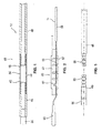
- FIGS. 1 to 3 show various components of the instrument in the disassembled state, which are in the context of the controlled from the handle 10 from bending the outer shaft 12 in the region of the shaft tip.
- Fig. 1 shows the outer shaft 12 of the instrument in the distal end portion 65 in the region of the tip without the provided in the assembled state in the outer shaft mounting parts.
- the outer shaft comprises, in the region of the tip, first and second rigid shank sections 48, 49 which are in Fig. 3 shown with further details. Between the two rigid shaft portions of the bendable portion 44 is arranged. In this case, a proximal end 45 of the region 44 is connected to the first, proximal shaft section 48 and a distal end 46 of the region 44 is connected to the second, distal shaft section 49.
- the bendable portion 44 acts as a hinge and has the function of allowing relative movement between the first and second shaft portions 48, 49 so that an angle between the first shaft portion 48 and the second shaft portion 49 can be adjusted.
- the bendable region has a tube 54 which connects the two rigid shaft sections 48, 49.
- the tube 54 is flexible.
- the tube 54 forms the outer wall of the outer shaft 12 in the region of the bendable region 44.
- the tube 54 is designed as a shrink tube, in particular as a silicone shrink tube, whereby the assembly facilitates and a gas-tight connection between the tube 54 and the two shaft portions 48, 49th is reached.
- Other mechanical connecting elements between the two shaft sections 48, 49 instead of the hose are possible.
- the proximal first shaft portion 48 is connected to the handle 10 (see Fig. 9 ).
- the first shaft portion 48 may have a profiled end 55 which is connected to the hose 54 ( Fig. 3 ).
- the second distally disposed shaft portion 49 also has a profiled end 55 for the tube 54 at the proximal end.
- a ceramic end sleeve 56 may be provided, in the region of which the ignition electrode, for example made of tungsten wire, is arranged.
- one-piece design of the two shaft portions 48, 49 may be formed in several parts and each having a support tube 50, 51, which are arranged between the tube 54 and a shaft tube.
- the support tubes 51, 50 or sleeves improve the stability of the outer shaft and are made of metal.
- the outer shaft tubes 52, 53 connected to the support tubes 51, 50 are made of plastic.
- the installation part is according to Fig. 2 in the region of the bendable area 44, as in FIG Fig. 4 shown.
- the fitting according to Fig. 2 includes the electrode 11 and a sleeve 47 surrounding the electrode.
- the sleeve 47 is made of a flexible material and has a plurality of transverse slots 57 which extend transversely to the longitudinal extent of the sleeve 47.
- the sleeve 47 may have a longitudinal slot (not shown) to further improve the flexibility and to receive the electrode in the angled state.
- the electrode 11 forms three sections.
- the first section 58 is rigid, for example, a steel wire with a diameter of about 1.5 mm. In the installed position, the first rigid portion 58 is proximal to the bendable portion 44. Distal to the rigid portion 58 is a second flexible portion 59 formed, for example, of spring steel wire having a diameter of about 0.5 mm. The second flexible portion 59 is in the installed position in the bendable portion of the shaft and allows by its flexibility a deflection of the bendable portion 44 upon actuation of the actuating mechanism on the handle 10th
- the electrode 11 is fixed.
- the fixation is achieved in that the electrode 11 is mechanically connected to the sleeve 47 and can transmit tensile and compressive forces.
- the connection of the electrode 11 with the sleeve 47 takes place at a fixing point 61 distally spaced from the proximal end 45 of the bendable portion 44.
- the fixing point 61 is in the installed position in the region of the distal end 46 of the bendable portion 44. This ensures that when moving the outer shaft, the entire length of the bendable portion 44 can be used for deflection. It is possible to displace the fixation site in the proximal or distal direction.
- connection in the region of the fixing point 61 can, as in Fig. 2 represented by a positive connection.
- Other connection types are possible.
- the electrode 11 is arcuately curved and engages in the sleeve 47 a.
- the electrode 11 forms a hook-shaped connection in the region of the fixing point 61, which is anchored to the sleeve 47. As a result, the transmission of forces is achieved safely.
- a third end portion 60 is provided, in the region of which the ignition electrode is arranged.
- This can be formed, for example, as tungsten wire with a diameter of about 0.5 mm.
- the electrode 11 is arranged axially at the proximal end or in the proximal area in a handle 10 and fixed in place.
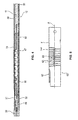
- FIG. 4 The installation condition is in Fig. 4 shown. It can be seen that the sleeve 47 is arranged in the region of the bendable region 44 and is surrounded radially on the outside by the hose 54. A difference to the example according to Fig. 2 is the formation of the fixation 61, which in Fig. 4 has a multiple curvature for better anchorage. In contrast to the prior art is in the embodiments FIGS. 1 to 5 a relative movement between the tip of the outer shaft and the electrode for exposing the electrode not possible. Thus, the instrument is suitable according to the FIGS. 1 to 5 primarily for coagulation.
- FIG. 5 shows a further embodiment in which the electrode 11 is formed as an inner shaft 11 and has a bendable portion 144 in a distal end portion 65.
- the bendable portion 144 is formed by slits 63 formed by laser cutting in the inner shaft 11, for example.
- the slots 63 are, for example, 0.2 mm apart, the slot width being between 0.1 and 1.0 mm.
- the slots 63 are arranged overlapping.
- This overlapping area 64 between the opposing slots 63 is, for example, 0.3 to 0.8 mm, particularly preferably 0.6 mm.
- a connecting element 62 is shown, wherein the connecting element 62 is formed as a flap integral with the inner shaft 11.
- the connecting element 62 is preferably formed by laser cutting, more preferably together with the slots 63. This allows a simple and cost-effective production.
- the connecting element 62 is mechanically connected to the inner shaft 11 in the bendable area 144 or distally of the bendable area 144.
- Fig. 6 shows the under reference to Fig. 5 described embodiment of the inner shaft 11, wherein the inner shaft 11 in Fig. 6 is represented by the connecting element 62 connected to the outer shaft 12.
- connection between the inner shaft 11 and the outer shaft 12 by the connecting element 62 is such that upon a relative movement of the outer shaft 12 relative to the inner shaft 11 via the connecting element 62 a force is exerted on the inner shaft 11 such that the inner shaft 11 in the angled portion 144th its orientation changes and is deflected.
- the angling of the inner shaft 11 is preferably perpendicular to a plane defined by the axial center A of the inner shaft 11 and the overlapping regions 64. A kinking of the inner shaft 11 in this plane is prevented by the arrangement of the slots 63.
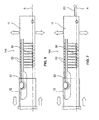
- Fig. 7 shows the case where an electrode 111 is provided in addition to the inner shaft 11. In this case, therefore, does not serve the inner shaft 11 as an electrode, as in the reference to the Fig. 5 and 6
- the inner shaft 11 encloses an electrode 111.
- the electrode 111 may be formed by various shapes. It may be in the form of a needle electrode, a spatula electrode or a sleeve, as an extension of the inner shaft 11, or another form.
- the inner shaft 11 may be formed as a contact means to the electrode. Alternatively, the electrode 111 may also extend through the entire inner shaft 11 into the handle 10 and be connected within the handle 10 to the electrical supply.
- FIG. 8 the connection of the actuating mechanism 13 with the rotary wheel 14 is shown.
- Fig. 8 and Fig. 4 belong together insofar as the continuation of the outer shaft 12 from Fig. 4 in the handle 10 according to Fig. 8 is shown.
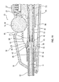
- the mechanism for converting the torque on the handle 10 in the translational movement of the outer shaft 12 is in the FIGS. 9 to 11 explained in more detail and is in connection with the embodiment according to FIGS. 1 to 4 and 8 discloses.
- the electrode 11 is fixedly mounted in the handle 10.
- the handle 10 has connections or supply lines for the electrode, which allow the power supply and possibly the gas supply of the electrode 11.
- one or more actuating means, such as push buttons 27 are provided on the handle.
- the electrode 11 is arranged in a displaceable outer shaft 12, which protrudes beyond the handle in the distal direction and is held in the housing 26 of the handle 10 (s. Fig. 9 ).
- the outer shaft 12 is made of an insulating material and surrounds the electrode 11 at least in the area outside the handle 10th
- the outer shaft 12 is displaceable relative to the electrode 11, so that by axial movement of the outer shaft 12, the alignment of the tip of the instrument can be adjusted.
- the instrument has a braking device which permanently loads the outer shaft 12 with a braking force and acts as a displacement safeguard.
- the braking force or even self-locking of the outer shaft 12 counteracts the resistance force during insertion of the instrument into a trocar and prevents the outer shaft 12 from being displaced unintentionally in the proximal direction.
- the advantage of the displacement protection of the outer shaft 12 also comes into play in other situations, for example in the preparation.
- the braking device has a force-locking clamping element, for example in the form of a clamping ring 33 ( FIG. 11 ).
- the clamping ring 33 may be an O-ring.
- Other passive braking means that counteract the resistance in the trocar are possible.
- the clamping ring 33 is at least indirectly connected to the outer shaft 12 and transmits the introduced into the outer shaft 12 axial forces in the handle 10, specifically in the housing 26 of the handle 10.
- the outer shaft 12 is connected to a sliding sleeve 25.
- the sliding sleeve 25 and the outer shaft 12 are arranged coaxially.
- the sliding sleeve 25 can be understood as an axial extension of the outer shaft 12 in the handle 10 into it.
- the clamping ring 33 is arranged in a matching groove such that the clamping ring 33 projects beyond the outer circumference of the sliding sleeve 25.
- the clamping ring 33 is supported in the handle 10 and generates a braking force, which counteracts a force acting on the outer shaft 12 in the longitudinal direction, for example, the resistance force in the trocar counteracts.
- the sliding sleeve 25 is arranged coaxially in an inner sleeve 29 which is fixedly connected to the housing 26, in particular by a retaining plate 21.
- the clamping ring 33 presses against the inner circumference of the inner sleeve 29 and thus generates an axially acting braking force.
- the inner sleeve 29 also forms the axial guidance of the sliding sleeve 25.
- the clamping ring 33 or generally the braking device can be arranged at a different location of the sliding sleeve 25. It is also possible to use more than one clamping ring 33, for example two clamping rings.
- the actuating mechanism 13 forms a transmission gear 15 which is connected to the outer shaft 12 for transmitting the thrust.
- the actuating mechanism 13 has a rotary wheel 14 which projects at least partially out of the housing 26 of the handle 10, so that a partial circumference of the rotary wheel 14 is accessible for actuation by a finger.
- the rotational movement of the rotary wheel 14 causes the axial displacement of the outer shaft 12.
- the function of the transmission gear 15 is to convert the introduced into the rotary wheel 14 torque so that the outer shaft is subjected to an increased thrust.
- the transmission gear 15 is adapted so that the finger force for actuating the rotary wheel 14 is smaller than the self-locking of the outer shaft 12.
- the transmission gear 15 comprises the rotary wheel 14, which in turn has a drive wheel 16 and at least one driven wheel 17 connected in a rotationally fixed manner to the drive wheel 16 ( FIG. 9 ).
- the output gear 17 is formed as a gear which is coaxially connected to the drive wheel 16.
- the drive wheel 16 may have for safe movement holding means, for example in the form of a corrugation on the outer circumference. As a result, the precise movement of the drive wheel 16 is ensured by means of a finger.
- the rotary wheel 14 may be formed as a stepped wheel, wherein the drive wheel 16 and the output gear 17 are formed integrally or integrally. Alternatively, the drive wheel 16 and the output gear 17 may be mechanically connected to each other.
- an extension can be provided as a finger lever.
- the diameter of the drive wheel 16 is greater than the diameter of the output gear 17.
- the outer diameter of the drive wheel 16 is approximately 2.8 times larger than the diameter of the output gear 17.
- the lever ratio is approximately 1: 2.8.
- the required finger power is thus about 2.8 times less than the self-locking of the outer shaft 12.
- the lever ratio can be in the range of 1: 2.6-3.0, in particular in the range 1: 2.7-2.9.
- Another advantage of the transmission gear is that the displacement or the radians traveled on the outer diameter of the drive wheel 16 is also 2.8 times or a multiple of the displacement of the outer shaft 12. This allows a particularly accurate adjustment of the shaft angle can be achieved.
- the outer diameter of the drive wheel 16 is approximately 12.5 mm.
- the required for the self-locking of the sliding outer shaft 12 braking force or clamping force is about 4 Newton.
- the conversion of the torque applied by the rotary wheel 14 in a translational thrust movement of the outer shaft 12 is achieved by a carriage 18 which is axially movable in the proximal and distal directions.
- the carriage 18 forms the connection between the outer shaft 12 and the transmission gear 15.
- the carriage 18, a first rack 19, which is arranged parallel to the thrust direction of the outer shaft 12.
- the first rack 19 is toothed with the output gear 17.
- the rack 19 is arranged outside.
- an internal rack may be provided which is formed on the inside of a longitudinal slot which extends parallel to the central axis of the electrode 11.
- the output gear 17 is then arranged in the longitudinal slot.
- Fig. 9 can be seen, the carriage 18 on a second rack 20, which is arranged parallel to the first rack 19.
- the drive wheel 16 is disposed between the two racks 19 and 20 and rotatably connected to a further output gear 17.
- the further driven gear 17 (not shown) meshes with the second rack 20.
- the symmetrical structure of the actuating mechanism 13 leads to a uniform force application and to an improved safety of the instrument.
- the two toothed racks 19, 20 form two arms which extend parallel to the longitudinal axis of the electrode 11 and / or the outer shaft 12.
- the two racks 19, 20 are arranged in a linear guide, which is formed by the holding plate 21.
- the holding plate 21 is firmly seated in the housing 26 and has two parallel openings 22 for the carriage 18 ( FIG. 10 ). Through the two openings 22, the racks 19, 20 are guided, so that a secure translational movement of the carriage 18 is possible.
- the rotary wheel 14 is disposed between the two racks 19, 20 in front of the holding plate 21, whereby a compact construction of the handle 10 is achieved.
- a further improvement in safety is achieved by a locking device on the carriage 18.
- the locking device is used to fix the outer shaft 12 in a predetermined position, in particular in the position in which the outer shaft 12 and the electrode in the longitudinal direction straight, are arranged stretched.
- the locking device may comprise means which ensure a self-locking of the movable outer shaft 12. Thus, it is possible to fix different angled positions of the distal end of the instrument.
- the braking device acts in any position of the carriage 18, so that a continuous adjustment of the outer shaft 12 is possible.
- the locking device on a first locking means 23, which is arranged at the proximal end of each of the first and second rack 19, 20.
- the first locking means 23 cooperates in the locking state with a second locking means 24, which is formed on the handle 10.
- the second latching means 24 is formed on the holding plate 21 in the form of a latching recess.
- the first locking means 23 may be a correspondingly formed locking lug, which is arranged laterally on the two toothed racks 19, 20.
- the locking device improves the overall safety of the instrument. It is also possible, the locking device regardless of the transmission gear and to use the braking device, for example, when the instrument is to be used exclusively with trocars with very high resistance, such as in reusable trocars with valve flap.
- the electrode 11 can be rotated in the circumferential direction, even if the outer shaft 12 is at least partially inserted in a trocar.
- the electrode 11 and the outer shaft 12 are each arranged rotatable relative to the handle 10 about its longitudinal axis.
- the sliding sleeve 25 is provided, through which the electrode 11 is guided.
- the sliding sleeve 25 connects the outer shaft 12 and the electrode 11. It is a non-rotatable and axially movable connection.
- the sliding sleeve 25 thus allows the transmission of torque from the outer shaft 12 to the electrode 11.
- the sliding sleeve 25 and thus the outer shaft 12 connected coaxially or flush with it can be displaced in the axial direction relative to the electrode 11, which causes the bending in the region 44 allows.
- This dual function (torque transmission and axial displaceability) is achieved in that the sliding sleeve 25 at least in sections has a profiling 37 on the inner circumference.
- the electrode 11 is correspondingly profiled in the area of the profiling 37 and is in positive engagement with the sliding sleeve 25 for transmitting the torque.
- the positive connection is designed so that the sliding sleeve 25 can be moved along the electrode 11 in both the distal and in the proximal direction.
- the sliding sleeve 25 at least three sections, namely a distal sleeve portion 30, a central sleeve portion 31 and a proximal sleeve portion 32.
- the profiling 37 is formed in the region of the proximal sleeve portion 32.
- the braking device, specifically the clamping ring 33 is arranged at the proximal end of the proximal sleeve section 32.
- the profiling 37 extends over a length which corresponds approximately to the length of the two toothed racks 19, 20. This ensures that the positive connection between the electrode 11 and the profiling 37 is maintained in each relative position of the sliding sleeve 25, so that the rotation function is independent of the respective position of the outer shaft 12.
- the profiling 37 is formed in the manner of a splined shaft profile. This increases the ease of assembly, since the correspondingly profiled electrode 11 can be inserted into the sliding sleeve substantially independent of their rotational position.
- the electrode 11 has a profile section 38 with a rectangular cross-section, as in FIG Fig. 10 shown.
- the proximal and distal ends of the profile section 38 of the electrode 11 are each tapered, as in FIG Fig. 11 shown.
- the electrode Distally and proximally from the profile section 38, the electrode has a substantially circular cross section in a conventional manner.
- the cross section can change into a non-rotationally symmetrical cross section.
- the electrode may, for example, be a spade electrode.
- the middle sleeve section 31 has a shoulder 42 in the distal and proximal directions. Between the two shoulders 42, a holding portion 43 is formed, which is rotatably connected to the carriage 18. The holding portion 43 forms a recess between the two shoulders 42. In this recess, a retaining ring 28 of the carriage 18 is arranged.
- the retaining ring 28 is partially open and surrounds the sliding sleeve only partially, so that the retaining ring 28 can be easily clipped onto the sliding sleeve 25 for mounting.
- the retaining ring 28 abuts against the two shoulders 42, so that axial forces or the thrust force in the proximal and distal directions for moving the outer shaft 12 can be transmitted.
- the middle sleeve portion 31 has an annular groove 35, in which a driver 36 of the retaining ring 28 is arranged.
- the driver 36 and the annular groove 35 are rotatable relative to each other, so that the sleeve 25 is freely rotatable in the retaining ring 28.
- the driver 36 also transmits the thrust in both axial directions.
- the retaining ring 28 is disposed between the two racks 19, 20 at its distal end. Specifically, a cross member 41 is provided, which connects the distal ends of the two racks 19, 20, as in Fig. 9 shown.
- the traverse 41 in turn is fixedly connected to the retaining ring 28 or integrally formed.
- the crossbar 41 and the retaining ring 28 can also be regarded as a traverse with two holding jaws arranged at the bottom, which surround the sliding sleeve 25 in part.
- the sliding sleeve 25 further includes a distal sleeve portion 30.
- the distal sleeve portion 30 is rotatably connected to the outer shaft 12.
- the connection can be made mechanically, for example by a fastening sleeve 34, which is arranged in the outer shaft 12 and crimped at the proximal end of the outer shaft 12 with the sliding sleeve 25.
- Other mounting options are conceivable.
- the distal sleeve portion 30 forms, together with the housing 26, an axial stop which determines the maximum extension position of the outer shaft 12.
- the inner sleeve 29 is coaxial with the electrode 11 and extends distally and proximally from the retaining plate 21, as in FIGS Figures 9 . 11 shown.
- the inner sleeve 29 forms a sleeve portion 39 with two guide webs 40, which extend parallel to the central axis of the inner sleeve 29.
- the guide webs 40 form bearing surfaces for the two racks 19, 20 and thus improve the stability of the linear guide.
- a portion of the peripheral wall of the inner sleeve 29 is removed in the region of the rotary wheel 14 to provide space for the rotary wheel 14, which is arranged in the housing 26 except for the required for the finger actuation circumferential segment without colliding with the inner sleeve 29. This contributes to a compact construction of the handle.
- the rotational function of the handle makes it suitable for the positioning of the angled electrode 11, so that the handle is not only particularly safe and inexpensive, but is easy to use.
- the instrument combines three functions:
- the stem tip and the third portion of the electrode is angled from the handle, so that the angle of the stem tip and the electrode can be changed in use.
- the outer shaft and thus the electrode are rotatable about their longitudinal axis, so that the electrode can be aligned, which is advantageous in non-rotationally symmetrical electrodes or to change the application position.
- the braking device prevents unwanted changes in position of the shaft tip, for example.
- the instrument according to the invention is additionally disclosed and claimed in connection with an electrosurgical unit, in particular for use on biological tissue, for example for argon plasma coagulation.
Landscapes
- Health & Medical Sciences (AREA)
- Surgery (AREA)
- Life Sciences & Earth Sciences (AREA)
- Engineering & Computer Science (AREA)
- Molecular Biology (AREA)
- Public Health (AREA)
- Heart & Thoracic Surgery (AREA)
- Medical Informatics (AREA)
- Nuclear Medicine, Radiotherapy & Molecular Imaging (AREA)
- Animal Behavior & Ethology (AREA)
- General Health & Medical Sciences (AREA)
- Biomedical Technology (AREA)
- Veterinary Medicine (AREA)
- Physics & Mathematics (AREA)
- Plasma & Fusion (AREA)
- Otolaryngology (AREA)
- Cardiology (AREA)
- Surgical Instruments (AREA)
Abstract
Description
- Die Erfindung bezieht sich auf ein elektrochirurgisches Instrument, insbesondere für die Argonplasma-Koagulation, mit den Merkmalen des Oberbegriffs des Anspruchs 1. Ein solches Instrument ist beispielsweise aus
US 2009/0125023 A1 bekannt. Die Erfindung betrifft ferner ein Gerät mit einem solchen Instrument. - Elektrochirurgische Instrumente der eingangs genannten Art werden zum Schneiden oder zum Koagulieren von Gewebe mit hochfrequentem Wechselstrom eingesetzt. Die Argonplasma-Koagulation ist eine spezielle Anwendungsform der Elektrochirurgie, bei der HF-Strom kontaktlos über ionisiertes Argongas übertragen wird.
- Die Wirkung des Energieeintrages erfolgt bei dem eingangs genannten bekannten Instrument dadurch, dass die exponierte Länge der Elektrode geändert wird. Dazu ist ein axial beweglicher Außenschaft vorgesehen, der die Elektrode isolierend umgibt und entlang der Elektrode verschoben werden kann, um diese je nach Bedarf zu exponieren.
- Eine zentrale Anforderung an derartige Instrumente ist die Möglichkeit der Ein-Hand-Bedienung. Dabei soll sich die Position des Instruments im OP-Feld möglichst nicht ändern. Dies bedeutet, dass die Griffhaltung bei der Bedienung des Instruments möglichst beibehalten werden soll, auch wenn der Außenschaft verschoben wird. Bei dem gattungsgemäßen Instrument wird dies durch ein Drehrad erreicht, das zentral im Handgriff des Instrumentes angeordnet ist und mit dem Zeigefinger betätigt werden kann. Das Drehrad treibt den Außenschaft an, der dadurch entlang der Elektrode axial verschoben werden kann.
- Der Außenschaft des bekannten Instrumentes ist starr und erstreckt sich gerade in distaler Richtung. In bestimmten Anwendungsfällen ist eine abgewinkelte Schaftstellung wünschenswert. Hierfür existieren zwar APC Applikatoren mit flexiblen Spitzen. Die Spitzen müssen aber vor der Anwendung manuell in die gewünschte Winkellage gebogen werden. Eine Änderung der Winkellage im Gebrauch ist nicht möglich.
- Der Erfindung liegt die Aufgabe zugrunde, das eingangs genannte elektrochirurgische Instrument dahingehend zu verbessern, dass eine Einstellung der Winkellage durch eine Betätigung im Bereich des Handgriffes, insbesondere auch während der Anwendung des Instrumentes möglich ist. Der Erfindung liegt ferner die Aufgabe zugrunde, ein Gerät mit einem solchen Instrument anzugeben.
- Erfindungsgemäß wird diese Aufgabe durch ein elektrochirurgisches Instrument mit den Merkmalen des Anspruchs 1 bzw. durch ein Gerät mit den Merkmalen des Anspruchs 16 gelöst.
- Die Erfindung umfasst demnach ein elektrochirurgisches Instrument, insbesondere für die Argonplasma-Koagulation, mit einem Handgriff, einem Außenschaft, der eine Elektrode und/oder einen Innenschaft umgibt und im Handgriff gehalten ist, und einem Betätigungsmechanismus am Handgriff zur Bewegung des Außenschafts in axialer Richtung relativ zur Elektrode/zum Innenschaft. Der Außenschaft ist mit dem Innenschaft/der Elektrode in einem distalen Endbereich des Außenschafts mechanisch verbunden. Der Innenschaft/Die Elektrode ist durch die Bewegung des Außenschafts relativ zum Innenschaft/zur Elektrode abwinkelbar.
- Das erfindungsgemäße Instrument hat einen einfachen Aufbau, da mit einer geringen Anzahl von Bauteilen die angestrebte Funktionalität, nämlich die Einstellung eines Winkels im Bereich der Schaftspitze durch eine Betätigung des Handgriffes erreicht wird. Daher eignet sich das erfindungsgemäße Instrument als kostengünstiges und damit wirtschaftliches Einwegprodukt.
- Vorzugsweise weist die Elektrode einen ersten, einen zweiten und einen dritten Abschnitt auf und erstreckt sich vom Handgriff aus durch den Außenschaft hindurch. Die Elektrode ist im zweiten Abschnitt flexibel ausgebildet. Der zweite Abschnitt der Elektrode ist bei dieser Ausführung über eine Hülse mit dem Außenschaft axial fixiert. Durch eine axiale Bewegung des Außenschafts wird dieser zusammen mit dem zweiten Abschnitt der Elektrode abgewinkelt und somit aus seiner Position quer zur Längsachse des Schafts ausgelenkt. Der erste Abschnitt der Elektrode ist proximal vom abwinkelbaren Bereich des Schafts angeordnet und ortsfest mit dem Handgriff verbunden und somit mit diesem fixiert. Der erste Abschnitt der Elektrode ist starr. Der dritte Abschnitt der Elektrode ist distal beabstandet vom proximalen Ende des abwinkelbaren Bereich des Schafts und somit distal vom zweiten Abschnitt der Elektrode angeordnet. Alle drei Abschnitte der Elektrode sind einstückig, nahtlos miteinander verbunden.
- Die vom Handgriff aus einstellbare Winkelposition des Außenschafts wird bei dieser Ausführungsform dadurch erreicht, dass die Elektrode mit dem Handgriff ortsfest verbunden und somit axial fixiert ist. Zusätzlich ist in einem Bereich, der distal vom proximalen Ende des abwinkelbaren Bereichs beabstandet ist ein erstes Ende der Hülse mit der Elektrode ortsfest verbunden und somit axial fixiert. Das zweite Ende der Hülse, welches proximal des abwinkelbaren Bereichs angeordnet ist, ist mit dem Außenschaft fixiert. Durch die Bewegung des Außenschafts wird der Abstand zwischen der Fixierstelle der Hülse mit der Elektrode und dem Handgriff, konkret dem distalen Ende des Handgriffes, verändert. Wird der Abstand verkürzt, wird der abwinkelbare Bereich des Außenschafts aus dem geraden Ruhezustand ausgelenkt und die Schaftspitze in die gewünschte Position bewegt. Dabei wird ein Winkel zwischen der Schaftspitze und der Längsachse des Handgriffes bzw. dem aus dem Handgriff ragenden Außenschaft eingestellt.
- Um die stauchende bzw. streckende Wirkung zu erreichen, ist die Fixierung der Elektrode distal vom proximalen Ende des abwinkelbaren Bereich beabstandet. Damit wird erreicht, dass der abwinkelbare Bereich im Bereich zwischen dem proximalen Ende und der Fixierstelle ausgelenkt wird. Je größer der Abstand zwischen dem proximalen Ende und der Fixierstelle ist, umso länger ist die für die Auslenkung wirksame Strecke. Besonders günstig ist die Fixierung der Elektrode im Bereich des distalen Endes des abwinkelbaren Bereichs, weil damit die gesamte Bereichslänge genutzt wird. Hierbei ist die Elektrode proximal vom abwinkelbaren Bereich starr und distal beabstandet von einem proximalen Ende des abwinkelbaren Bereichs am Außenschaft fixiert.
- Es versteht sich allgemein, dass die Elektrode zusätzlich zu der distalen Fixierung am Außenschaft mittels der Hülse auch proximal in Längsrichtung der Elektrode mit dem Handgriff fixiert ist, um die Kräfte abzustützen, die über die distale Fixierung der Elektrode eingeleitet werden.
- Unter dem abgewinkelten Zustand wird allgemein ein Zustand verstanden, bei dem der Außenschaft entlang seiner exponierten Gesamtlänge nicht geradlinig ist, so dass die Schaftspitze in eine Richtung weist, die von der Längsachse des aus dem Handgriff ragenden Außenschafts abweicht. Im abgewinkelten Zustand schließen das proximale Ende und das distale Ende des abwinkelbaren Bereichs einen Winkel ein. Im Bereich zwischen dem proximalen und distalen Ende kann der Bereich im abgewinkelten Zustand gekrümmt sein.
- Die Größe des Winkels hängt von dem Auslenkungsgrad des Außenschafts im Bereich des abwinkelbaren Bereichs ab, der wiederum durch die Axialbewegung des Außenschafts bestimmt wird.
- Durch Ausschieben des Außenschafts wird der Abstand zwischen der Fixierstelle der Hülse mit der Elektrode und dem Handgriff vergrößert, so dass der gekrümmte bzw. abgewinkelte Bereich gestreckt und der Winkel zwischen den beiden Schaftabschnitten verringert bzw. vollständig aufgehoben wird, so dass der Außenschaft in den geraden Ruhezustand zurückkehrt.
- Die Elektrode hat damit eine Doppelfunktion. Zum einen dient sie zur Leitung des elektrischen Stroms. Zum anderen hat die Elektrode eine mechanische Funktion, nämlich als Schub- bzw. Zugstange, die die vom Betätigungsmechanismus über den Außenschaft eingeleiteten Zug- bzw. Schubkräfte überträgt und damit die Auslenkung des abwinkelbaren Bereichs bewirkt. Zur sicheren Übertragung der Kräfte ist die Elektrode im Bereich proximal vom abwinkelbaren Bereich starr ausgebildet. Da die Elektrode im zweiten Abschnitt flexibel ist, folgt die Elektrode der Krümmung des abwinkelbaren Bereichs.
- Die Doppelfunktion der Elektrode hat den Vorteil, dass auf zusätzliche mechanische Bauteile, wie beispielsweise Zugseile verzichtet wird.
- Außerdem ermöglicht die Erfindung, die Einhandbedienung beizubehalten, so dass das Instrument ergonomisch günstig bedient werden kann.
- Weitere bevorzugte Ausführungsformen der Erfindung sind in den Unteransprüchen angegeben.
- Vorzugsweise ist die Elektrode am distalen Ende des abwinkelbaren Bereichs fixiert. Dies hat den Vorteil, dass die gesamte Länge des abwinkelbaren Bereichs für die Auslenkung genutzt wird.
- Der abwinkelbare Bereich weist vorzugsweise eine flexible, insbesondere längs- und/oder quergeschlitzte, Hülse auf, die die Elektrode umgibt. Die Hülse dient als Scharnier für den abwinkelbaren Bereich. Bei einer besonders bevorzugten Ausführung ist die Elektrode mit der Hülse zur Übertragung von Druck- und Zugkräften verbunden. Dabei werden die durch den Betätigungsmechanismus über den Außenschaft eingeleiteten Kräfte von der Elektrode auf die Hülse übertragen, die aufgrund ihrer flexiblen Eigenschaften im abwinkelbaren Bereich aus der geradlinigen Ruhelage ausgelenkt und gekrümmt wird.
- Ein proximales Ende der Hülse kann mit einem ersten starren Außenschaftabschnitt verbunden sein. Dadurch werden die über die Elektrode eingeleiteten Kräfte abgestützt, so dass die Hülse durch die Betätigung des Betätigungsmechanismus ausgelenkt wird.
- Vorzugsweise ist das distale Ende der Hülse mit einem zweiten starren Außenschaftabschnitt verbunden, der den dritten Abschnitt der Elektrode aufnimmt, der als Zündelektrode dient. Der abwinkelbare Bereich ist also zwischen den beiden starren Außenschaftabschnitten angeordnet.
- Zur Verbesserung der Stabilität des Außenschafts können der erste und/oder der zweite Außenschaftabschnitt jeweils ein Stützrohr aufweisen, das einerseits mit der Hülse und andererseits mit einem Außenschaftrohr aus Kunststoff verbunden ist.
- Bei dem Stützrohr kann es sich um ein metallisches Stützrohr handeln, das eine ausreichende Festigkeit zur Aufnahme der im Gebrauch auftretenden Kräfte aufweist. Das Stützrohr ist also einerseits mit der Hülse und andererseits mit einem Schaftrohr verbunden und kann aus Kunststoff sein. Das proximale Schaftrohr führt zum Handgriff. Das distale Schaftrohr bildet den zweiten starren Schaftabschnitt, der beispielsweise in einer keramischen Endhülse enden kann, die mit dem Schaftrohr verbunden ist.
- Vorzugsweise weist der abwinkelbare Bereich einen Schlauch, insbesondere einen Schrumpfschlauch auf, der die Außenschaftaußenwand im Bereich des abwinkelbaren Bereichs bildet. Dadurch wird eine gasdichte Ummantelung geschaffen, die zudem die Elektrode nach außen elektrisch isoliert. Der Schlauch ist flexibel, um das Abwinkeln des Bereichs zu ermöglichen.
- Bei einer weiteren Ausführungsform ist vorgesehen, dass der Innenschaft im distalen Endbereich einen abwinkelbaren Bereich aufweist und der Innenschaft in diesem Bereich flexibel ausgebildet ist, wobei der abwinkelbare Bereich des Innenschafts durch die Bewegung des Außenschafts relativ zum Innenschaft abwinkelbar ist.
- Die Zug- und Druckkräfte zur Abwinklung des Innenschafts werden durch die Relativbewegung zwischen dem Außen- und Innenschaft erzeugt. Der Innenschaft ist ortsfest mit dem Handgriff verbunden.
- Vorzugsweise ist der Innenschaft als Elektrode ausgebildet und dient als elektrischer Leiter beispielsweise eines Hochfrequenzstroms für monopolares Koangulieren.
- Hierdurch wird erreicht, dass ein abwinkelbarer Innenschaft zur Verfügung gestellt wird der über einen weiteren Freiheitsgrad verfügt und gleichzeitig auf einfache Weise als Elektrode genutzt werden kann, wodurch das separate Vorsehen einer Elektrode obsolet wird.
- Diese Ausführung hat den Vorteil, dass Einbauteile zur Verbindung der Elektrode mit dem Außenschaft entfallen. Das Lumen des Innenrohres steht für den Durchfluss von Medien, bspw. zum Absaugen, zur Verfügung.
- Andererseits ist denkbar, dass eine Elektrode innerhalb des Innenschafts angeordnet ist. Hierbei umgibt der Innenschaft die Elektrode. Die Elektrode wird beim Abwinkeln des Innenschafts zusammen mit dem Innenschaft mitbewegt. Der Innen- und Außenschaft sind voneinander elektrisch isoliert.
- Die Fixierung zwischen Innen- und Außenschaft, vorzugsweise im Bereich der Schaftspitze, kann durch ein Verbindungselement mechanisch vorgenommen werden. Das Verbindungselement ist vorzugsweise als Band, Stift, Lasche oder Steg ausgebildet. Das Verbindungselement ist vorzugsweise flexibel sowie vorzugsweise aus Metall ausgebildet.
- Das Verbindungselement ist einerseits mit dem Außenschaft und andererseits mit dem Innenschaft verbunden.
- Vorzugsweise ist das Verbindungselement im Bereich des abwinkelbaren Bereichs des Innenschafts und noch bevorzugter distal des abwinkelbaren Bereichs des Innenschafts angeordnet und überbrückt somit den abwinkelbaren Bereich des Innenschafts.
- Der abwinkelbare Bereich des Innenschafts kann in dem entsprechenden Wandabschnitt Schlitze aufweisen. Die besondere Anordnung der Schlitze ermöglicht, dass der Innenschaft in axialer Richtung Kräfte aufnimmt und sich quer zur Längsachse des Innenschafts biegen lässt.
- Andererseits kann der abwinkelbare Bereich des Innenschafts durch gegenüberliegende Schlitze ausgebildet sein. Diese Schlitze werden vorzugsweise durch ein Laserstrahlschneideverfahren ausgebildet.
- Die Schlitze reichen vorzugsweise jeweils über die Achsmitte des Innenschafts, sodass eine Art Knick-Strohhalm Effekt erreicht wird. Die gegenüberliegenden Schlitze sind in diesem Fall versetzt zueinander ausgebildet und überlappen sich im Bereich der jeweiligen Schlitzspitzen.
- Denkbar ist, dass sich die jeweiligen Schlitzspitzen nur geringfügig überlappen und daher ein geringer Überlappungsgrad vorliegt. Der Überlappungsgrad kann so gewählt werden, dass die Stabilität des Innenschafts sichergestellt ist und gleichzeitig ein ausreichender Abwinklungswinkel ermöglicht wird.
- Vorzugsweise sind die Schlitze in Längsrichtung des Innenschafts mit gleichen Abständen zueinander angeordnet, wodurch ein gleichmäßiges Abwinkeln des Innenschafts ermöglicht wird.
- Die Schlitze sind bevorzugt kammartig ausgebildet, wobei durch die Versetzung der Schlitze eine Art Ineinandergreifen der gegenüberliegenden Schlitze ermöglicht wird.
- Je größer die Überlappung im Überlappungsbereich ist, desto größer ist der Federweg eines Einzelelements. Größere Überlappung führt daher zu einer geringeren Rückstellkraft.
- Der Winkelbereich, in dem der Innenschaft im abwinkelbaren Bereich abwinkelbar ist, ist größer, je mehr Schlitze in das Rohr eingebracht werden. Außerdem vergrößert sich der Winkelbereich bei gleichbleibender Schlitzanzahl, je größer die Schlitzbreite ist.
- Der Bereich, indem die Schlitze überlappen, beschreibt eine Federgeometrie, wobei der Innenschaft nicht plastisch verformt wird, sondern die entstehenden Federelemente dafür sorgen, dass eine elastische Verformung des Innenschafts ermöglicht wird.
- Die Breite der Verbindungsstege darf nicht zu groß gewählt werden, da die elastische Verformung sonst in eine plastische Verformung übergeht und der Innenschaft zerstört werden kann.
- Das Verbindungselement ist vorzugsweise integral mit dem Innenschaft ausgebildet und außerhalb der Achsmitte angeordnet, sodass durch die mechanische Verbindung zwischen dem Außenschaft und dem Innenschaft durch die Relativbewegung zwischen dem Außenschaft und dem Innenschaft eine Kraft über das Verbindungselement übermittelbar ist. Die Kraft greift außerhalb der Achsmitte an. Durch die Kraft wird der Weg auf der Seite des Verbindungselements verkürzt und der Innenschaft knickt in Richtung des Verbindungselements ab.
- Der Handgriff weist in einer bevorzugten Ausführung eine Bremseinrichtung auf, die eine Bremskraft auf den Außenschaft ausübt. Der Betätigungsmechanismus bildet ein Drehrad mit einem Übersetzungsgetriebe, das mit dem Außenschaft zur Übertragung der Schubkraft verbunden ist.
- Die Sicherheit des Instruments gegen ungewolltes Bewegen der Schaftspitze beispielsweise bei der Verwendung zusammen mit einem Trokar wird durch die Bremseinrichtung verbessert. Die von der Bremseinrichtung auf den Außenschaft ausgeübte Bremskraft verhindert, dass dieser bei einer Anwendung, beispielsweise beim Einführen durch einen Trokar in proximaler Richtung verschoben wird. Die Bremskraft führt also zu einer Selbsthemmung des Außenschafts, die diesen gegen ungewolltes Verschieben sichert. Damit wird eine ungewollte Bewegung der Schaftspitze vermieden.
- Zur Änderung der Winkellage der Schaftspitze ist der Außenschaft durch Betätigen eines Drehrades mit einer Betätigungskraft beaufschlagbar. Diese Kraft wird üblicherweise durch den Finger des Anwenders aufgebracht. Der Widerstand des Drehrades liegt in einem als ergonomisch angenehm empfundenen Bereich. Dadurch kann das Instrument, insbesondere die Abwinkelung des Schafts, leicht und sicher vom Anwender erfolgen. Dazu weist das Instrument bei dieser Ausführung ein Übersetzungsgetriebe auf, das durch den Betätigungsmechanismus gebildet ist und mit dem Außenschaft zur Übertragung der Schubkraft verbunden ist. Das Übersetzungsgetriebe gleicht die von der Bremseinrichtung aufgebrachte Bremskraft aus, so dass das Drehrad bzw. allgemein der Betätigungsmechanismus leicht zu bedienen ist.
- Der Außenschaft kann drehfest oder drehbar im Handgriff gelagert sein. Wenn der Außenschaft in Umfangsrichtung drehbar im Handgriff gelagert ist, kann durch eine Drehung des Schafts die Position der abgewinkelten Schaftspitze verändert werden. Somit kann die Applikationsposition bei abgewinkeltem Außenschaft leicht verändert werden.
- Es versteht sich, dass das Drehrad in zwei Richtungen (Uhrzeigersinn / Gegenuhrzeigersinn) drehbar ist, sodass der Außenschaft in distaler Richtung und in proximaler Richtung bewegt werden kann.
- Zusammengefasst wird bei dieser Ausführung die Sicherheit des Instruments verbessert, weil der Außenschaft gegen ungewolltes Verschieben durch die Bremseinrichtung gesichert ist. Gleichzeitig wird eine leichtgängige Bedienung des Instruments beibehalten, da der Betätigungsmechanismus ein Übersetzungsgetriebe bildet, das die vom Anwender aufgebrachte Fingerkraft in die auf den Außenschaft wirkende Schubkraft umwandelt. Das Übersetzungsgetriebe wirkt dabei wie eine Hebelanordnung, die die Schubkraft im Vergleich zur Fingerkraft erhöht.
- Zur weiteren Erhöhung der Hebelkraft kann das Drehrad einen hebelartigen Vorsprung aufweisen, der sich radial ausgehend vom Außenumfang des Drehrades erstreckt und mit dem Finger betätigbar ist.
- Vorzugsweise umfasst das Drehrad ein Antriebsrad und wenigstens ein drehfest mit dem Antriebsrad verbundenes Abtriebsrad, das mit dem Außenschaft zur Übertragung der Schubkraft verbunden ist. Der Durchmesser des Abtriebsrades ist kleiner als der Durchmesser des Antriebsrades. Damit wird auf einfache Weise die für eine leichtgängige Betätigung des Außenschafts erforderliche Übersetzung erreicht. Ein weiterer Vorteil dieser Ausführungsform ist die kostengünstige und sichere Konstruktion, die diese Ausführungsform bietet.
- Der Betätigungsmechanismus kann einen in Schubrichtung axial beweglichen Schlitten umfassen, der einerseits mit dem Außenschaft und andererseits mit dem Übersetzungsgetriebe verbunden ist. Damit wird eine robuste und einfache Konstruktion geschaffen, die eine sichere Übertragung der vom Anwender aufgebrachten Antriebskraft auf den Außenschaft bewirkt.
- Der Schlitten kann wenigstens eine erste Zahnstange aufweisen, die parallel zur Schubrichtung angeordnet ist und mit dem Abtriebsrad kämmt. Diese Ausführung ermöglicht eine einfache und sichere Umwandlung der Drehbewegung des Drehrades in eine lineare Bewegung des Außenschafts.
- Für eine verbesserte Kraftübertragung kann der Schlitten eine zweite Zahnstange parallel zur ersten Zahnstange aufweisen, wobei das Antriebsrad zwischen den beiden Zahnstangen angeordnet und mit einem weiteren Abtriebsrad drehfest verbunden ist. Das weitere Abtriebsrad ist mit der zweiten Zahnstange verzahnt.
- Vorzugsweise weist der Handgriff eine Halteplatte mit einer Linearführung auf, in der der Schlitten axial beweglich angeordnet ist. Die Linearführung weist wenigstens einen Durchbruch, insbesondere zwei parallele Durchbrüche, für den Schlitten auf. Die Halteplatte ermöglicht einen kompakten Aufbau, der einen geringen Bauraum für die Lagerung des Schlittens erfordert.
- Der Bremsmechanismus kann ein Klemmelement, insbesondere einen Klemmring aufweisen, wobei das Klemmelement im Handgriff gehalten ist und den Außenschaft mit der Bremskraft beaufschlagt. Das Klemmelement bildet ein passives Bremsmittel, das einen einfachen und kostengünstigen Aufbau des Instrumentes ermöglicht.
- Bei einer bevorzugten Ausführungsform weist der Betätigungsmechanismus eine Arretiereinrichtung auf, mit der der Außenschaft in wenigstens einer Position, insbesondere in einer vollständig ausgefahrenen Position, fixierbar ist. Die Arretiereinrichtung ist besonders für Trokare geeignet, die einen besonders großen Widerstand beim Einführen des Instrumentes bewirken, wie beispielsweise wiederverwendbare Trokare mit Ventilklappe. Die Arretiereinrichtung dient dazu, den Außenschaft zusätzlich zum Bremsmechanismus zu fixieren, so dass größere Axialkräfte vom Außenschaft übertragen werden können, ohne dass dieser relativ zur Elektrode verschoben wird.
- Dabei kann die Arretiereinrichtung wenigstens ein erstes Rastmittel umfassen, das am Schlitten angeordnet ist. Ein zweites Rastmittel ist am Handgriff, insbesondere an der Halteplatte angeordnet, das mit dem ersten Rastmittel zur Fixierung des Außenschafts verbindbar ist. Die beiden Rastmittel haben den Vorteil, dass diese einfach herstellbar sind, beispielsweise durch ein Spritzgussverfahren, und gleichzeitig eine sichere Fixierung des Außenschafts ermöglichen.
- Bei einer besonders bevorzugten Ausführungsform sind die Elektrode und der Außenschaft relativ zum Handgriff jeweils um ihre Längsachse drehbar angeordnet. Die Elektrode ist durch eine Schiebehülse geführt, die den Außenschaft und die Elektrode drehfest und axial beweglich verbindet.
- Diese Ausführungsform ist für nicht-rotationssymmetrische Elektroden, wie beispielsweise Spatelelektroden geeignet oder kann dazu verwendet werden, bei abgewinkeltem Außenschaft die Applikationsposition durch eine Drehbewegung um die Schaftlängsachse zu verändern. Damit kann auf einfache Weise die Elektrode in Umfangsrichtung ausgerichtet werden. Diese Ausführungsform hat den Vorteil, dass die Drehung der Elektrode auch dann möglich ist, wenn sich das Instrument im Trokar befindet. Die Drehbewegung wird bei dieser Ausführungsform durch den Außenschaft eingeleitet, der über die Schiebehülse mit der Elektrode drehfest verbunden ist. Die Schiebehülse hat zudem die Funktion, die Relativbeweglichkeit zwischen dem Außenschaft und der Elektrode herzustellen. Dazu bildet die Schiebehülse eine drehfeste und axial bewegliche Verbindung zwischen dem Außenschaft und der Elektrode. Da der Außenschaft aus dem Handgriff hervorragt, sind keine zusätzlichen Bauteile erforderlich, um die Elektrode zu drehen. Der Anwender greift einfach den Außenschaft und dreht diesen zusammen mit der Elektrode.
- Dabei kann die Schiebhülse zumindest abschnittsweise eine Profilierung auf dem Innenumfang aufweisen, die mit der zumindest abschnittsweise entsprechend profilierten Elektrode zur Übertragung eines Drehmoments formschlüssig in Eingriff ist. Diese Ausführung ist kostengünstig und sicher, da eine entsprechend profilierte Schiebehülse einfach herstellbar ist und durch den Formschluss eine sichere Momentenübertragung erreicht wird.
- Ein kostengünstiger und einfacher Aufbau wird vorzugsweise dadurch erreicht, dass die Schiebehülse und der Schlitten drehbeweglich und in axialer Richtung der Schiebehülse zur Übertragung der Schubkraft fest verbunden sind. Der Schlitten weist einen Haltering auf, der die Schiebehülse zumindest teilumfänglich umgibt.
- Die Erfindung wird nachfolgend mit weiteren Einzelheiten und mit Bezug auf die beigefügten schematischen Figuren näher erläutert. Diese zeigen:
- Fig. 1
- einen Längsschnitt des Außenschafts nach einem erfindungsgemäßen Ausführungsbeispiel;
- Fig. 2
- einen Längsschnitt durch die Einbauteile des Außenschafts, insbesondere die Hülse und Elektrode;
- Fig. 3
- eine Seitenansicht der starren Schaftabschnitte;
- Fig. 4
- einen Längsschnitt durch den Außenschaft eines Instruments nach einem erfindungsgemäßen Ausführungsbeispiel im Bereich des abwinkelbaren Bereichs;
- Fig. 5
- eine Seitenansicht des Innenschafts des Instruments;
- Fig. 6
- eine perspektivische Seitenansicht des Innenschafts des Instruments nach
Figur 4 mit Außenschaft; - Fig. 7
- eine perspektivische Seitenansicht des Innenschafts des Instruments nach
Figur 5 mit Elektrode; - Fig. 8
- einen Längsschnitt durch den Handgriff des Instruments nach
Figur 4 ; - Fig. 9
- eine perspektivische Ansicht des Instrumentes nach einem erfindungsgemäßen Ausführungsbeispiel, bei dem das Gehäuse teilweise entfernt ist;
- Fig. 10
- einen Querschnitt des Instrumentes gemäß
Fig. 6 , wobei das Drehrad weggelassen ist, und - Fig. 11
- einen Längsschnitt des Instruments gemäß
Fig. 6 entlang der Mittelachse. - Das Ausführungsbeispiel gemäß den
Figuren 1 bis 8 zeigt ein elektrochirurgisches Instrument, das für die Bearbeitung von biologischem Gewebe beispielsweise zur Argonplasma-Koagulation einsetzbar ist. Die Erfindung ist nicht auf Instrumente für die Argonplasma-Koagulation eingeschränkt, sondern ist allgemein für Instrumente im Bereich der Elektrochirurgie einsetzbar, bei denen eine Schaftspitze aktiv, d.h. vom Handgriff aus, bewegt wird. - Bei der Elektrode 11 des Ausführungsbeispiels kann es sich bspw. um eine Hohlelektrode handeln, die einen Kanal für die Gaszuführung aufweist (APC-Elektrode). Andere Elektroden sind möglich.
-
Figuren 1 bis 3 zeigen verschiedene Komponenten des Instruments im demontierten Zustand, die im Zusammenhang mit der vom Handgriff 10 aus gesteuerten Abwinklung des Außenschafts 12 im Bereich der Schaftspitze stehen. -
Fig. 1 zeigt den Außenschaft 12 des Instruments im distalen Endbereich 65 im Bereich der Spitze ohne die im montierten Zustand im Außenschaft vorgesehenen Einbauteile. Der Außenschaft umfasst im Bereich der Spitze einen ersten und zweiten starren Schaftabschnitt 48, 49, der inFig. 3 mit weiteren Details gezeigt ist. Zwischen den beiden starren Schaftabschnitten ist der abwinkelbare Bereich 44 angeordnet. Dabei sind ein proximales Ende 45 des Bereichs 44 mit dem ersten, proximalen Schaftabschnitt 48 und ein distales Ende 46 des Bereichs 44 mit dem zweiten, distalen Schaftabschnitt 49 verbunden. - Der abwinkelbare Bereich 44 wirkt wie ein Gelenk und hat die Funktion, eine Relativbewegung zwischen dem ersten und zweiten Schaftabschnitt 48, 49 zu erlauben, so dass ein Winkel zwischen dem ersten Schaftabschnitt 48 und dem zweiten Schaftabschnitt 49 eingestellt werden kann.
- Dazu weist der abwinkelbare Bereich einen Schlauch 54 auf, der die beiden starren Schaftabschnitte 48, 49 verbindet. Der Schlauch 54 ist flexibel. Der Schlauch 54 bildet die Außenwand des Außenschafts 12 im Bereich des abwinkelbaren Bereichs 44. Vorteilhafterweise ist der Schlauch 54 als Schrumpfschlauch, insbesondere als Silikon-Schrumpfschlauch ausgeführt, wodurch die Montage erleichtert und eine gasdichte Verbindung zwischen dem Schlauch 54 und den beiden Schaftabschnitten 48, 49 erreicht wird. Andere mechanische Verbindungselemente zwischen den beiden Schaftabschnitten 48, 49 anstelle des Schlauches sind möglich.
- Der proximale erste Schaftabschnitt 48 ist mit dem Handgriff 10 verbunden (siehe
Fig. 9 ). - Zur Verbindung des distalen Endes des ersten Schaftabschnitts 48 mit dem Schlauch 45 kann der erste Schaftabschnitt 48 ein profiliertes Endstück 55 aufweisen, das mit dem Schlauch 54 verbunden ist (
Fig. 3 ). Der zweite distal angeordnete Schaftabschnitt 49 weist am proximalen Ende ebenfalls ein profiliertes Endstück 55 für den Schlauch 54 auf. Am distalen Ende des starren Schaftabschnitts 49 kann eine keramische Endhülse 56 vorgesehen sein, in deren Bereich die Zündelektrode, beispielsweise aus Wolframdraht angeordnet ist. - Anstelle der in
Fig. 1 dargestellten einteiligen Ausführung der beiden Schaftabschnitte 48, 49 können diese mehrteilig ausgebildet sein und jeweils ein Stützrohr 50, 51 aufweisen, die zwischen dem Schlauch 54 und einem Schaftrohr angeordnet sind. Die Stützrohre 51, 50 bzw. -hülsen verbessern die Stabilität des Außenschafts und sind aus Metall hergestellt. Die Außenschaftrohre 52, 53, die mit den Stützrohren 51, 50 verbunden sind, sind aus Kunststoff hergestellt. - Im montierten Zustand befindet sich das Einbauteil gemäß
Fig. 2 im Bereich des abwinkelbaren Bereichs 44, wie inFig. 4 dargestellt. Das Einbauteil gemäßFig. 2 umfasst die Elektrode 11 sowie eine Hülse 47, die die Elektrode umgibt. Die Hülse 47 ist aus einem flexiblen Material und weist mehrere Querschlitze 57 auf, die sich quer zur Längserstreckung der Hülse 47 erstrecken. Die Hülse 47 kann zur weiteren Verbesserung der Flexibilität und zur Aufnahme der Elektrode im abgewinkelten Zustand einen Längsschlitz aufweisen (nicht dargestellt). - Die Elektrode 11 bildet drei Abschnitte. Der erste Abschnitt 58 ist starr, beispielsweise aus einem Stahldraht mit einem Durchmesser von ca. 1,5 mm. In der eingebauten Lage befindet sich der erste starre Abschnitt 58 proximal vom abwinkelbaren Bereich 44. Distal des starren Abschnitts 58 ist ein zweiter flexibler Abschnitt 59 vorgesehen, der beispielsweise aus Federstahldraht mit einem Durchmesser von ca. 0,5 mm gebildet ist. Der zweite flexible Abschnitt 59 befindet sich in der Einbaulage im abwinkelbaren Bereich des Schafts und ermöglicht durch seine Flexibilität eine Auslenkung des abwinkelbaren Bereichs 44 bei Betätigung des Betätigungsmechanismus am Handgriff 10.
- Dazu ist die Elektrode 11 fixiert. Die Fixierung wird dadurch erreicht, dass die Elektrode 11 mit der Hülse 47 mechanisch verbunden ist und Zug- und Druckkräfte übertragen kann. Die Verbindung der Elektrode 11 mit der Hülse 47 erfolgt an einer Fixierstelle 61, die vom proximalen Ende 45 des abwinkelbaren Bereichs 44 distal beabstandet ist. Im Beispiel gemäß
Fig. 2 befindet sich die Fixierstelle 61 in der Einbaulage im Bereich des distalen Endes 46 des abwinkelbaren Bereichs 44. Dadurch wird erreicht, dass beim Verschieben des Außenschafts die gesamte Länge des abwinkelbaren Bereichs 44 zur Auslenkung genutzt werden kann. Es ist möglich, die Fixierstelle in proximaler oder distaler Richtung zu versetzen. - Die Verbindung im Bereich der Fixierstelle 61 kann, wie in
Fig. 2 dargestellt, durch eine formschlüssige Verbindung erfolgen. Andere Verbindungsarten sind möglich. Bei dem Beispiel gemäßFig. 2 ist die Elektrode 11 bogenförmig gekrümmt und greift in die Hülse 47 ein. Mit anderen Worten bildet die Elektrode 11 im Bereich der Fixierstelle 61 eine hakenförmige Verbindung, die mit der Hülse 47 verankert ist. Dadurch wird die Übertragung der Kräfte sicher erreicht. - Distal des zweiten flexiblen Abschnitts 59 der Elektrode 11 ist ein dritter Endabschnitt 60 vorgesehen, in dessen Bereich die Zündelektrode angeordnet ist. Diese kann beispielsweise als Wolframdraht mit einem Durchmesser von ca. 0,5 mm ausgebildet sein.
- Nicht dargestellt ist in
Fig. 2 , dass zusätzlich zur Fixierstelle 61 die Elektrode 11 am proximalen Ende bzw. im proximalen Bereich in einem Handgriff 10 axial angeordnet und ortsfest fixiert ist. - Der Einbauzustand ist in
Fig. 4 dargestellt. Darin ist zu sehen, dass die Hülse 47 im Bereich des abwinkelbaren Bereichs 44 angeordnet ist und radial außen vom Schlauch 54 umgeben wird. Ein Unterschied zu dem Beispiel gemäßFig. 2 ist die Ausbildung der Fixierstelle 61, die inFig. 4 eine Mehrfachkrümmung zur besseren Verankerung aufweist. Im Unterschied zu dem Stand der Technik ist bei den AusführungsbeispielenFiguren 1 bis 5 eine Relativbewegung zwischen der Spitze des Außenschafts und der Elektrode zum Exponieren der Elektrode nicht möglich. Damit eignet sich das Instrument gemäß denFiguren 1 bis 5 in erster Linie zum Koagulieren. -
Figur 5 zeigt eine weitere Ausführungsform, bei der die Elektrode 11 als Innenschaft 11 ausgebildet ist und in einem distalen Endbereich 65 einen abwinkelbaren Bereich 144 aufweist. - Der abwinkelbare Bereich 144 ist durch Schlitze 63 ausgebildet, die beispielsweise durch Laserschneiden in dem Innenschaft 11 ausgebildet werden. Die Schlitze 63 sind beispielsweise 0,2 mm voneinander beabstandet, wobei die Schlitzbreite zwischen 0,1 und 1,0 mm beträgt.
- In der Achsmitte A des Innenschafts 11 sind die Schlitze 63 überlappend angeordnet. Dieser Überlappungsbereich 64 zwischen den gegenüberliegenden Schlitzen 63 beträgt beispielsweise 0,3 bis 0,8 mm, besonders bevorzugt 0,6 mm.
- Weiterhin ist in
Fig. 5 im distalen Endbereich 65 des Innenschafts 11 ein Verbindungselement 62 abgebildet, wobei das Verbindungselement 62 als Lasche integral mit dem Innenschaft 11 ausgebildet ist. Das Verbindungselement 62 ist vorzugsweise durch Laserschneiden geformt, noch bevorzugter gemeinsam mit den Schlitzen 63. Hierdurch wird eine einfache und kostengünstige Fertigung ermöglicht. Das Verbindungselement 62 ist im abwinkelbaren Bereich 144 oder distal des abwinkelbaren Bereichs 144 mit dem Innenschaft 11 mechanisch verbunden. -
Fig. 6 zeigt die unter Bezug aufFig. 5 beschriebene Ausbildung des Innenschafts 11, wobei der Innenschaft 11 inFig. 6 durch das Verbindungselement 62 verbunden mit dem Außenschaft 12 abgebildet ist. - Die Verbindung zwischen dem Innenschaft 11 und dem Außenschaft 12 durch das Verbindungselement 62 ist dergestalt, das bei einer Relativbewegung des Außenschafts 12 gegenüber dem Innenschaft 11 über das Verbindungselement 62 eine Kraft auf den Innenschaft 11 ausgeübt wird derart, das der Innenschaft 11 im abwinkelbaren Bereich 144 seine Ausrichtung ändert und ausgelenkt wird.
- Die Abwinklung des Innenschafts 11 geschieht vorzugsweise Senkrecht zu einer Ebene, die durch die Achsmitte A des Innenschafts 11 und die Überlappungsbereiche 64 definiert wird. Ein Abknicken des Innenschafts 11 in dieser Ebene wird durch die Anordnung der Schlitze 63 verhindert.
-
Fig. 7 zeigt den Fall, in dem eine Elektrode 111 zusätzlich zum Innenschaft 11 vorgesehen ist. In diesem Fall dient also nicht der Innenschaft 11 als Elektrode, wie dies in den unter Bezug auf dieFig. 5 und6 beschriebenen Ausführungsformen der Fall ist, sondern der Innenschaft 11 umschließt eine Elektrode 111. Die Elektrode 111 kann durch verschiedene Formen gebildet sein. Sie kann in Form einer Nadelelektrode, eine Spatelelektrode oder einer Hülse, als Fortsatz des Innenschafts 11, oder einer anderen Form gebildet sein. Der Innenschaft 11 kann als Kontaktmittel zur Elektrode ausgebildet sein. Alternativ, kann die Elektrode 111 sich auch durch den gesamten Innenschaft 11 bis in den Handgriff 10 erstrecken und innerhalb des Handgriffs 10 mit der elektrischen Versorgung verbunden sein. - In
Figur 8 ist die Anbindung des Betätigungsmechanismus 13 mit dem Drehrad 14 gezeigt.Fig. 8 undFig. 4 gehören insofern zusammen, als die Weiterführung des Außenschafts 12 ausFig. 4 in den Handgriff 10 gemäßFig. 8 gezeigt ist. Die Mechanik zur Umwandlung des Drehmomentes am Handgriff 10 in die translatorische Bewegung des Außenschafts 12 ist in denFiguren 9 bis 11 näher erläutert und wird im Zusammenhang mit dem Ausführungsbeispiel gemäßFiguren 1 bis 4 und 8 offenbart. - Die Elektrode 11 ist im Handgriff 10 ortsfest gelagert. Der Handgriff 10 weist Anschlüsse oder Zuleitungen für die Elektrode auf, die die Stromversorgung und ggf. die Gaszufuhr der Elektrode 11 ermöglichen. Außerdem sind ein oder mehrere Betätigungsmittel, beispielsweise Druckknöpfe 27 am Handgriff vorgesehen. Die Elektrode 11 ist in einem verschiebbaren Außenschaft 12 angeordnet, der über den Handgriff in distaler Richtung vorsteht und im Gehäuse 26 des Handgriffs 10 gehalten ist (s.
Fig. 9 ). Der Außenschaft 12 ist aus einem isolierenden Material hergestellt und umgibt die Elektrode 11 zumindest im Bereich außerhalb des Handgriffes 10. - Der Außenschaft 12 ist relativ zur Elektrode 11 verschiebbar, so dass durch eine Axialbewegung des Außenschafts 12 die Ausrichtung der Spitze des Instruments eingestellt werden kann.
- Das Instrument weist eine Bremseinrichtung auf, die den Außenschaft 12 permanent mit einer Bremskraft beaufschlagt und als Verschiebesicherung wirkt. Die Bremskraft oder auch Selbsthemmung des Außenschafts 12 wirkt der Widerstandskraft beim Einführen des Instrumentes in einen Trokar entgegen und verhindert, dass der Außenschaft 12 ungewollt in proximaler Richtung verschoben wird. Der Vorteil der Verschiebesicherung des Außenschafts 12 kommt auch in anderen Situationen zum Tragen, bspw. bei der Präparation.
- Konkret weist die Bremseinrichtung ein kraftschlüssig wirkendes Klemmelement, beispielsweise in der Form eines Klemmrings 33 auf (
Figur 11 ). Der Klemmring 33 kann ein O-Ring sein. Andere passive Bremsmittel, die der Widerstandskraft im Trokar entgegenwirken, sind möglich. Der Klemmring 33 ist zumindest indirekt mit dem Außenschaft 12 verbunden und überträgt die in den Außenschaft 12 eingeleiteten Axialkräfte in den Handgriff 10, konkret in das Gehäuse 26 des Handgriffs 10. Dazu ist der Außenschaft 12 mit einer Schiebehülse 25 verbunden. Die Schiebehülse 25 und der Außenschaft 12 sind koaxial angeordnet. Die Schiebehülse 25 kann als eine axiale Verlängerung des Außenschafts 12 in den Handgriff 10 hinein verstanden werden. Am distalen Ende der Schiebhülse 25 ist der Klemmring 33 in einer passenden Nut angeordnet derart, dass der Klemmring 33 über den Außenumfang der Schiebehülse 25 vorsteht. Der Klemmring 33 ist im Handgriff 10 abgestützt und erzeugt eine Bremskraft, die einer Kraft, die in Längsrichtung auf den Außenschaft 12 wirkt, beispielsweise der Widerstandskraft im Trokar entgegen wirkt. - Konkret ist die Schiebehülse 25 koaxial in einer Innenhülse 29 angeordnet, die fest mit dem Gehäuse 26, insbesondere durch eine Halteplatte 21, verbunden ist. Der Klemmring 33 drückt gegen den Innenumfang der Innenhülse 29 und erzeugt so eine axial wirkende Bremskraft. Die Innenhülse 29 bildet zugleich die axiale Führung der Schiebehülse 25.
- Der Klemmring 33 bzw. allgemein die Bremseinrichtung kann an einer anderen Stelle der Schiebehülse 25 angeordnet sein. Es ist auch möglich, mehr als einen Klemmring 33, beispielsweise zwei Klemmringe zu verwenden.
- Um zu vermeiden, dass die Bremseinrichtung die Handhabung des Instrumentes erschwert, bildet der Betätigungsmechanismus 13 ein Übersetzungsgetriebe 15, das mit dem Außenschaft 12 zur Übertragung der Schubkraft verbunden ist.
- Der Betätigungsmechanismus 13 weist ein Drehrad 14 auf, das zumindest teilweise aus dem Gehäuse 26 des Handgriffes 10 vorsteht, so dass ein Teilumfang des Drehrades 14 für die Betätigung durch einen Finger zugänglich ist. Die Drehbewegung des Drehrades 14 bewirkt die axiale Verschiebung des Außenschafts 12. Durch Betätigung des Drehrades 14 im Uhrzeigersinn bzw. gegen den Uhrzeigersinn kann der Außenschaft in distaler Richtung vorgeschoben bzw. in proximaler Richtung zurückgezogen werden. Mit anderen Worten kann der Außenschaft 12 hin und her bewegt werden.
- Die Funktion des Übersetzungsgetriebes 15 besteht darin, das in das Drehrad 14 eingeleitete Drehmoment so zu wandeln, dass der Außenschaft mit einer erhöhten Schubkraft beaufschlagt wird. Das Übersetzungsgetriebe 15 ist so angepasst, dass die Fingerkraft zur Betätigung des Drehrades 14 kleiner als die Selbsthemmung des Außenschafts 12 ist.
- Das Übersetzungsgetriebe 15 umfasst das Drehrad 14, das wiederum ein Antriebsrad 16 und wenigstens ein drehfest mit dem Antriebsrat 16 verbundenes Abtriebsrad 17 aufweist (
Figur 9 ). Das Abtriebsrad 17 ist als Zahnrad ausgebildet, das koaxial mit dem Antriebsrad 16 verbunden ist. Das Antriebsrad 16 kann zur sicheren Bewegung Haltemittel beispielweise in Form einer Riffelung auf dem Außenumfang aufweisen. Dadurch ist das präzise Bewegen des Antriebsrads 16 mittels eines Fingers gewährleistet. Das Drehrad 14 kann als Stufenrad ausgebildet sein, wobei das Antriebsrad 16 und das Abtriebsrad 17 einstückig bzw. integral ausgebildet sind. Alternativ können das Antriebsrad 16 und das Abtriebsrad 17 mechanisch miteinander verbunden sein. - Am Drehrad kann einen Fortsatz als Fingerhebel vorgesehen sein.
- Wie in
Fig. 9 gut zu erkennen, ist der Durchmesser des Antriebsrades 16 größer als der Durchmesser des Abtriebsrades 17. Konkret ist der Außendurchmesser des Antriebrades 16 um das ca. 2,8-fache größer als der Durchmesser des Abtriebsrades 17. Somit beträgt das Hebelverhältnis ca. 1:2,8. Die erforderliche Fingerkraft ist damit um das 2,8-fache geringer als die Selbsthemmung des Außenschafts 12. Das Hebelverhältnis kann im Bereich von 1:2,6-3,0 liegen, insbesondere im Bereich 1:2,7-2,9. - Ein weiterer Vorteil des Übersetzungsgetriebes besteht darin, dass der Verschiebeweg bzw. das zurückgelegte Bogenmaß am Außendurchmesser des Antriebsrades 16 ebenfalls das 2,8-fache bzw. ein Vielfaches des Verschiebewegs des Außenschafts 12 beträgt. Damit kann eine besonders genaue Einstellung des Schaftwinkels erreicht werden.
- Im vorliegenden Ausführungsbeispiel beträgt der Außendurchmesser des Antriebsrades 16 ca. 12,5 mm. Die für die Selbsthemmung des verschiebbaren Außenschafts 12 erforderliche Bremskraft bzw. Klemmkraft beträgt ca. 4 Newton.
- Die Umwandlung des vom Drehrad 14 aufgebrachten Drehmomentes in eine translatorische Schubbewegung des Außenschafts 12 wird durch einen Schlitten 18 erreicht, der in proximaler und distaler Richtung axial beweglich ist. Der Schlitten 18 bildet die Verbindung zwischen dem Außenschaft 12 und dem Übersetzungsgetriebe 15. Dazu weist der Schlitten 18 eine erste Zahnstange 19 auf, die parallel zur Schubrichtung des Außenschafts 12 angeordnet ist. Die erste Zahnstange 19 ist mit dem Abtriebsrad 17 verzahnt. Andere Konstruktionen zur Umwandlung der Drehbewegung in eine translatorische Bewegung sind möglich. Im Beispiel gemäß
Fig. 9 ist die Zahnstange 19 außenliegend angeordnet. Alternativ kann eine innenliegende Zahnstange vorgesehen sein, die an der Innenseite eines Längsschlitzes ausgebildet ist, der sich parallel zur Mittelachse der Elektrode 11 erstreckt. Das Abtriebsrad 17 ist dann in dem Längsschlitz angeordnet. - Wie
Fig. 9 zu entnehmen, weist der Schlitten 18 eine zweite Zahnstange 20 auf, die parallel zur ersten Zahnstange 19 angeordnet ist. Das Antriebsrad 16 ist zwischen den beiden Zahnstangen 19 und 20 angeordnet und mit einem weiteren Abtriebsrad 17 drehfest verbunden. Das weitere Abtriebsrad 17 (nicht dargestellt) kämmt mit der zweiten Zahnstange 20. Der symmetrische Aufbau des Betätigungsmechanismus 13 führt zu einer gleichmäßigen Krafteinleitung sowie zu einer verbesserten Sicherheit des Instruments. - Die beiden Zahnstangen 19, 20 bilden zwei Arme, die sich parallel zur Längsachse der Elektrode 11 und / oder des Außenschafts 12 erstrecken. Die beiden Zahnstangen 19, 20 sind in einer Linearführung angeordnet, die durch die Halteplatte 21 gebildet ist. Die Halteplatte 21 sitzt fest im Gehäuse 26 und weist zwei parallele Durchbrüche 22 für den Schlitten 18 auf (
Figur 10 ). Durch die beiden Durchbrüche 22 sind die Zahnstangen 19, 20 geführt, so dass eine sichere translatorische Bewegung des Schlittens 18 möglich ist. Das Drehrad 14 ist zwischen den beiden Zahnstangen 19, 20 vor der Halteplatte 21 angeordnet, wodurch ein kompakter Aufbau des Handgriffs 10 erreicht wird. - Es ist auch möglich, eine einzige Zahnstange bspw. nur die erste Zahnstange 19 vorzusehen.
- Eine weitere Verbesserung der Sicherheit wird durch eine Arretiereinrichtung am Schlitten 18 erreicht. Die Arretiereinrichtung dient dazu, den Außenschaft 12 in einer vorgegebenen Position zu fixieren, insbesondere in der Position in der der Außenschaft 12 und die Elektrode in Längsrichtung gerade, gestreckt angeordnet sind. Die Arretiereinrichtung kann Mittel umfassen, die eine Selbsthemmung des beweglichen Außenschafts 12 sicherstellen. So ist es möglich verschiedene abgewinkelte Positionen des distalen Endes des Instruments zu fixieren.
- Im Unterschied zu der Arretiereinrichung, die den 18 Schlitten in einer bestimmten Position festlegt, wirkt die Bremseinrichtung in jeder Position des Schlittens 18, so dass eine stufenlose Verstellung des Außenschafts 12 möglich ist.
- Konkret weist die Arretiereinrichtung ein erstes Rastmittel 23 auf, das am proximalen Ende jeweils der ersten und zweiten Zahnstange 19, 20 angeordnet ist. Das erste Rastmittel 23 wirkt im Arretierzustand mit einem zweiten Rastmittel 24 zusammen, das am Handgriff 10 ausgebildet ist. Konkret ist das zweite Rastmittel 24 an der Halteplatte 21 in der Form einer Rastausnehmung ausgebildet. Das erste Rastmittel 23 kann eine entsprechend ausgebildete Rastnase sein, die seitlich an den beiden Zahnstangen 19, 20 angeordnet ist.
- Die Arretiereinrichtung verbessert die Gesamtsicherheit des Instruments. Es ist auch möglich, die Arretiereinrichtung unabhängig vom Übersetzungsgetriebe und der Bremseinrichtung zu verwenden, beispielsweise dann, wenn das Instrument ausschließlich mit Trokaren mit sehr hoher Widerstandskraft, wie bspw. bei wiederverwendbaren Trokaren mit Ventilklappe, verwendet werden soll.
- Ein weiterer Vorteil des Instruments besteht darin, dass die Elektrode 11 in Umfangsrichtung gedreht bzw. ausgerichtet werden kann, selbst dann, wenn der Außenschaft 12 zumindest teilweise in einem Trokar eingeführt ist. Dazu sind die Elektrode 11 und der Außenschaft 12 jeweils relativ zum Handgriff 10 um ihre Längsachse drehbar angeordnet. Mit anderen Worten können die Elektrode 11 und der Außenschaft 12 zusammen verdreht werden. Dazu ist die Schiebehülse 25 vorgesehen, durch die die Elektrode 11 geführt ist. Die Schiebehülse 25 verbindet den Außenschaft 12 und die Elektrode 11. Dabei handelt es sich um eine drehfeste und axial bewegliche Verbindung. Die Schiebehülse 25 ermöglicht also die Übertragung eines Drehmoments vom Außenschaft 12 auf die Elektrode 11. Gleichzeitig kann die Schiebehülse 25 und somit der mit dieser koaxial bzw. fluchtend verbundene Außenschaft 12 relativ zur Elektrode 11 in axialer Richtung verschoben werden, was die Abwinkelung im Bereich 44 ermöglicht.
- Diese Doppelfunktion (Drehmomentübertragung und axiale Verschiebbarkeit) wird dadurch erreicht, dass die Schiebehülse 25 zumindest abschnittsweise eine Profilierung 37 auf dem Innenumfang aufweist. Die Elektrode 11 ist im Bereich der Profilierung 37 entsprechend profiliert und steht zur Übertragung des Drehmoments formschlüssig mit der Schiebehülse 25 in Eingriff. Die formschlüssige Verbindung ist so gestaltet, dass die Schiebehülse 25 entlang der Elektrode 11 sowohl in distaler als auch in proximaler Richtung bewegt werden kann.
- Konkret weist die Schiebehülse 25 wenigstens drei Abschnitte auf, nämlich einen distalen Hülsenabschnitt 30, einen mittleren Hülsenabschnitt 31 und einen proximalen Hülsenabschnitt 32. Die Profilierung 37 ist im Bereich des proximalen Hülsenabschnitts 32 ausgebildet. Die Bremseinrichtung, konkret der Klemmring 33 ist am proximalen Ende des proximalen Hülsenabschnittes 32 angeordnet. Die Profilierung 37 erstreckt sich über eine Länge, die in etwa der Länge der beiden Zahnstangen 19, 20 entspricht. Damit wird erreicht, dass die formschlüssige Verbindung zwischen der Elektrode 11 und der Profilierung 37 in jeder Relativlage der Schiebehülse 25 beibehalten wird, so dass die Drehfunktion unabhängig von der jeweiligen Lage des Außenschafts 12 gegeben ist.
- Wie in
Fig. 10 dargestellt, ist die Profilierung 37 nach Art eines Keilwellenprofils ausgebildet. Dies erhöht die Montagefreundlichkeit, da die entsprechend profilierte Elektrode 11 in die Schiebehülse im Wesentlichen unabhängig von deren Drehposition eingeschoben werden kann. Die Elektrode 11 weist einen Profilabschnitt 38 mit einem rechteckigen Querschnitt auf, wie inFig. 10 dargestellt. Das proximale und distale Ende des Profilabschnitts 38 der Elektrode 11 verjüngt sich jeweils, wie inFig. 11 gezeigt. Distal und proximal vom Profilabschnitt 38 weist die Elektrode in herkömmlicher Weise einen im Wesentlichen kreisförmigen Querschnitt auf. Am distalen Ende der Elektrode kann der Querschnitt in einen nicht-rotationssymmetrischen Querschnitt übergehen. Die Elektrode kann bspw. eine Spatelektrode sein. - Der mittlere Hülsenabschnitt 31 weist in distaler und proximaler Richtung jeweils eine Schulter 42 auf. Zwischen den beiden Schultern 42 ist ein Haltebereich 43 ausgebildet, der drehbeweglich mit dem Schlitten 18 verbunden ist. Der Haltebereich 43 bildet eine Ausnehmung zwischen den beiden Schultern 42. In dieser Ausnehmung ist ein Haltering 28 des Schlittens 18 angeordnet. Der Haltering 28 ist teilweise geöffnet und umschließt die Schiebehülse nur teilumfänglich, so dass der Haltering 28 zur Montage einfach auf die Schiebehülse 25 aufgeclipst werden kann. Der Haltering 28 schlägt an den beiden Schulter 42 an, so dass Axialkräfte bzw. die Schubkraft in proximaler und distaler Richtung zum Bewegen des Außenschafts 12 übertragen werden können. Als weitere Sicherheit weist der mittlere Hülsenabschnitt 31 eine Ringnut 35 auf, in der ein Mitnehmer 36 des Halterings 28 angeordnet ist. Der Mitnehmer 36 und die Ringnut 35 sind relativ zueinander drehbeweglich, so dass die Hülse 25 im Haltering 28 frei drehbar ist. Der Mitnehmer 36 überträgt ebenfalls die Schubkraft in beiden axialen Richtungen.
- Der Haltering 28 ist zwischen den beiden Zahnstangen 19, 20 an deren distalen Ende angeordnet. Konkret ist eine Traverse 41 vorgesehen, die die distalen Enden der beiden Zahnstangen 19, 20 verbindet, wie in
Fig. 9 gezeigt. Die Traverse 41 wiederum ist mit dem Haltering 28 fest verbunden bzw. einstückig ausgebildet. Die Traverse 41 und der Haltering 28 können auch als eine Traverse mit zwei unten angeordneten Haltebacken angesehen werden, die die Schiebehülse 25 teilumfänglich umgeben. - Zwischen der Traverse 41 und der Halteplatte 21 ist ein ausreichender Abstand vorgesehen, so dass der Schlitten 18 am Drehrad 14 vorbei bewegt werden kann, ohne mit dem Drehrad 14 zu kollidieren.
- Die Schiebehülse 25 umfasst ferner einen distalen Hülsenabschnitt 30. Der distale Hülsenabschnitt 30 ist drehfest mit dem Außenschaft 12 verbunden. Die Verbindung kann mechanisch erfolgen, beispielsweise durch eine Befestigungshülse 34, die im Außenschaft 12 angeordnet und am proximalen Ende des Außenschafts 12 mit der Schiebehülse 25 vercrimpt ist. Andere Befestigungsmöglichkeiten sind denkbar. Der distale Hülsenabschnitt 30 bildet zusammen mit dem Gehäuse 26 einen axialen Anschlag, der die maximale Auszugsposition des Außenschafts 12 bestimmt.
- Zur Unterstützung der Linearführung des Schlittens 18 weist der Handgriff die vorstehend erwähnte Innenhülse 29 auf, die fest mit der Halteplatte 21 verbunden ist. Die Innenhülse 29 ist koaxial zur Elektrode 11 angeordnet und erstreckt sich distal und proximal von der Halteplatte 21, wie in den
Figuren 9 ,11 dargestellt. Auf der distalen Seite der Halteplatte 21 bildet die Innenhülse 29 einen Hülsenabschnitt 39 mit zwei Führungsstegen 40, die sich parallel zur Mittelachse der Innenhülse 29 erstrecken. Die Führungsstege 40 bilden Auflageflächen für die beiden Zahnstangen 19, 20 und verbessern so die Stabilität der Linearführung. - Wie in
Fig. 11 gezeigt, ist ein Teil der Umfangswand der Innenhülse 29 im Bereich des Drehrades 14 entfernt, um Raum für das Drehrad 14 zu schaffen, das bis auf das für die Fingerbetätigung erforderliche Umfangssegment im Gehäuse 26 angeordnet ist, ohne mit der Innenhülse 29 zu kollidieren. Dies trägt zu einem kompakten Aufbau des Handgriffs bei. - Die Drehfunktion des Handgriffes macht diesen für die Positionierung der abgewinkelten Elektrode 11 geeignet, so dass der Handgriff nicht nur besonders sicher und kostengünstig ist, sondern bedienungsfreundlich ist.
- Zusammengefasst kombiniert das Instrument drei Funktionen:
- Durch den Betätigungsmechanismus wird vom Handgriff aus die Schaftspitze und der dritte Abschnitt der Elektrode abgewinkelt, so dass der Winkel der Schaftspitze und der Elektrode im Gebrauch verändert werden kann. Der Außenschaft und damit die Elektrode sind um deren Längsachse drehbar, so dass die Elektrode ausgerichtet werden kann, was bei nicht-rotationssymmetrischen Elektroden bzw. zur Änderung der Applikationsposition vorteilhaft ist. Die Bremseinrichtung verhindert ungewollte Positionsänderungen der Schaftspitze, bspw. wenn der Außenschaft in einem Trokar bewegt wird.
- Das erfindungsgemäße Instrument wird zusätzlich auch im Zusammenhang mit einem Elektrochirurgiegerät, insbesondere für Anwendung am biologischen Gewebe, beispielsweise für die Argonplasma-Koagulation offenbart und beansprucht.
-
- 10
- Handgriff
- 11
- Elektrode, Innenschaft
- 12
- Außenschaft
- 13
- Betätigungsmechanismus
- 14
- Drehrad
- 15
- Übersetzungsgetriebe
- 16
- Antriebsrad
- 17
- Abtriebsrad
- 18
- Schlitten
- 19
- erste Zahnstange
- 20
- zweite Zahnstange
- 21
- Halteplatte
- 22
- Durchbruch
- 23
- erstes Rastmittel
- 24
- zweites Rastmittel
- 25
- Schiebehülse
- 26
- Gehäuse
- 27
- Druckknopf
- 28
- Haltering
- 29
- Innenhülse
- 30
- distaler Hülsenabschnitt
- 31
- mittlerer Hülsenabschnitt
- 32
- proximaler Hülsenabschnitts
- 33
- Klemmring
- 34
- Befestigungshülse
- 35
- Ringnut
- 36
- Mitnehmer
- 37
- Profilierung
- 38
- Profilabschnitt
- 39
- Hülsenabschnitt
- 40
- Führungssteg
- 41
- Traverse
- 42
- Schulter
- 43
- Haltebereich
- 44
- abwinkelbarer Bereich
- 45
- proximales Ende
- 46
- distales Ende
- 47
- Hülse
- 48
- erster Außenschaftabschnitt
- 49
- zweiter Außenschaftabschnitt
- 50
- Stützrohr
- 51
- Stützrohr
- 52
- Außenschaftrohr
- 53
- Außenschaftrohr
- 54
- Schlauch
- 55
- Endstück
- 56
- Endhülse
- 57
- Querschlitze
- 58
- erster Abschnitt der Elektrode
- 59
- zweiter Abschnitt der Elektrode
- 60
- dritter Abschnitt der Elektrode
- 61
- Fixierstelle
- 62
- Verbindungselement
- 63
- Schlitze
- 64
- Überlappungsbereich
- 65
- distaler Endbereich
- 111
- Elektrode
- 144
- abwinkelbarer Bereich
Claims (16)
- Elektrochirurgisches Instrument, für eine Anwendung am biologischen Gewebe, insbesondere für die Argonplasma-Koagulation, mit- einem Handgriff (10),- einem Außenschaft (12), der eine Elektrode und/oder einen Innenschaft (11, 111) umgibt und im Handgriff (10) gehalten ist, und- einem Betätigungsmechanismus (13) am Handgriff (10) zur Bewegung des Außenschafts (12) in axialer Richtung relativ zur Elektrode und/oder zum Innenschaft (11, 111),dadurch gekennzeichnet, dass
der Außenschaft (12) und der Innenschaft und/oder die Elektrode (11, 111) in einem distalen Endbereich (65) des Außenschafts (12) mechanisch miteinander verbunden sind derart, dass der Innenschaft und/oder die Elektrode (11, 111) durch die Bewegung des Außenschafts (12) relativ zum Innenschaft und/oder zur Elektrode (11, 111) abwinkelbar ist. - Instrument nach Anspruch 1,
dadurch gekennzeichnet, dass
der Außenschaft (12) im distalen Endbereich (65) einen abwinkelbaren Bereich (44) aufweist und die Elektrode (11) in diesem Bereich (44) flexibel ausgebildet ist, wobei der abwinkelbare Bereich (44) des Außenschafts (12) durch die Bewegung des Außenschafts (12) relativ zur Elektrode (11) abwinkelbar ist. - Instrument nach Anspruch 2,
dadurch gekennzeichnet, dass
die Elektrode (11) an einem distalen Ende (46) des abwinkelbaren Bereichs (44) fixiert ist. - Instrument nach einem der Ansprüche 2 bis 3,
dadurch gekennzeichnet, dass
der abwinkelbare Bereich (44) eine flexible, insbesondere längs- und/oder quergeschlitzte, Hülse (47) aufweist, die die Elektrode (11) umgibt, und vorzugsweise die Elektrode (11) mit der Hülse (47) zur Übertragung von Druck- und Zugkräften verbunden ist. - Instrument nach Anspruch 4,
dadurch gekennzeichnet, dass
ein proximales Ende (45) der Hülse (47) mit einem ersten starren Schaftabschnitt (48) verbunden ist, und vorzugsweise ein distales Ende (46) der Hülse (47) mit einem zweiten starren Schaftabschnitt (49) verbunden ist. - Instrument nach einem der vorhergehenden Ansprüche,
dadurch gekennzeichnet, dass
der abwinkelbare Bereich (44) einen Schlauch (54), insbesondere einen Schrumpfschlauch, aufweist, der die Schaftaußenwand im Bereich des abwinkelbaren Bereichs (44) bildet. - Instrument nach Anspruch 1,
dadurch gekennzeichnet, dass
der Innenschaft (11) im distalen Endbereich (65) einen abwinkelbaren Bereich (144) aufweist und der Innenschaft (11) in diesem Bereich (144) flexibel ausgebildet ist, wobei der abwinkelbare Bereich (144) des Innenschafts (11) durch die Bewegung des Außenschafts (12) relativ zum Innenschaft (11) abwinkelbar ist. - Instrument nach Anspruch 7,
dadurch gekennzeichnet, dass
der Innenschaft (11) als Elektrode ausgebildet ist oder die Elektrode (111) innerhalb des Innenschafts (11) angeordnet ist. - Instrument nach Anspruch 7 oder 8,
dadurch gekennzeichnet, dass
der Innenschaft (11) im distalen Endbereich (65) mit dem Außenschaft (12), vorzugsweise im Bereich der Schaftspitze, durch ein Verbindungselement (62) mechanisch verbunden ist, wobei das Verbindungselement (62) vorzugsweise als Band, Stift, Lasche oder Steg und flexibel sowie vorzugsweise aus Metall ausgebildet ist. - Instrument nach einem der Ansprüche 7 bis 9,
dadurch gekennzeichnet, dass
der abwinkelbare Bereich (144) des Innenschafts (11) durch gegenüberliegende Schlitze (63) ausgebildet ist, die vorzugsweise jeweils über die Achsmitte des Innenschafts (11) reichen, um einen Überlappungsbereich (64) auszubilden. - Instrument nach Anspruch 10,
dadurch gekennzeichnet, dass
die Schlitze (63) ungefähr 0,2 mm zueinander beabstandet sind, und die Überlappung der Schlitze (63) bezüglich der Achsmitte vorzugsweise ungefähr 0,6 mm beträgt. - Instrument nach Anspruch 10 oder 11,
dadurch gekennzeichnet, dass
die Schlitzbreite der Schlitze (63) 0,1 bis 1,0 mm beträgt. - Instrument nach einem der vorhergehenden Ansprüche,
dadurch gekennzeichnet, dass
der Handgriff (10) eine Bremseinrichtung aufweist, die eine permanente Bremskraft auf den Außenschaft (12) ausübt, und der Betätigungsmechanismus (13) ein Drehrad (14) mit einem Übersetzungsgetriebe (15) bildet, das mit dem Außenschaft (12) zur Übertragung der axialen Kraft verbunden ist - Instrument nach Anspruch 12,
dadurch gekennzeichnet, dass
das Drehrad (14) ein Antriebsrad (16) und wenigstens ein drehfest mit dem Antriebsrad (16) verbundenes Abtriebsrad (17) umfasst, das mit dem Außenschaft (12) zur Übertragung der Schubkraft verbunden ist, wobei der Durchmesser des Abtriebsrades (17) kleiner als der Durchmesser des Antriebsrades (16) ist und der Betätigungsmechanismus (13) vorzugsweise einen in Schubrichtung axial beweglichen Schlitten (18) umfasst, der einerseits mit dem Außenschaft (12) und andererseits mit dem Übersetzungsgetriebe (15) verbunden ist und der Schlitten (18) noch bevorzugter wenigstens eine erste Zahnstange (19) aufweist, die parallel zur Schubrichtung angeordnet ist und mit dem Abtriebsrad (17) kämmt. - Instrument nach einem der vorhergehenden Ansprüche,
dadurch gekennzeichnet, dass
die Elektrode (11, 111) und/oder der Innenschaft (11) und der Außenschaft (12) relativ zum Handgriff (10) jeweils um ihre Längsachse drehbar angeordnet sind, wobei die Elektrode (11, 111) und/oder der Innenschaft (11) durch eine Schiebehülse (25) geführt ist, die den Außenschaft (12) und die Elektrode (11, 111) und/oder den Innenschaft (11) drehfest und axial beweglich verbindet und die Schiebehülse (25) vorzugsweise zumindest abschnittsweise eine Profilierung auf dem Innenumfang aufweist, die mit der/dem zumindest abschnittsweise entsprechend profilierten Innenschaft/Elektrode (11, 111) zur Übertragung eines Drehmomentes formschlüssig in Eingriff ist und noch bevorzugter die Schiebehülse (25) und der Schlitten (18) drehbeweglich und in axialer Richtung der Schiebehülse (25) zur Übertragung der Schubkraft fest verbunden sind, wobei der Schlitten (18) einen Haltering (28) aufweist, der die Schiebehülse (25) zumindest teilumfänglich umgibt. - Elektrochirurgiegerät, für eine Anwendung am biologischen Gewebe, insbesondere für die Argonplasma-Koagulation, mit einem Instrument nach einem der Ansprüche 1 bis 15.
Priority Applications (8)
| Application Number | Priority Date | Filing Date | Title |
|---|---|---|---|
| PL15167061T PL3092966T3 (pl) | 2015-05-11 | 2015-05-11 | Instrument elektrochirurgiczny |
| EP15167061.9A EP3092966B1 (de) | 2015-05-11 | 2015-05-11 | Elektrochirurgisches instrument |
| BR102016009917-0A BR102016009917B1 (pt) | 2015-05-11 | 2016-05-03 | Instrumento eletrocirúrgico e equipamento eletrocirúrgico para uma utilização em tecido biológico |
| US15/147,587 US10751106B2 (en) | 2015-05-11 | 2016-05-05 | Electrosurgical instrument and device with such an instrument |
| KR1020160056195A KR102201450B1 (ko) | 2015-05-11 | 2016-05-09 | 전기 외과 도구 및 이러한 도구를 구비한 디바이스 |
| RU2016118137A RU2703501C2 (ru) | 2015-05-11 | 2016-05-10 | Электрохирургический инструмент и электрохирургический аппарат для применения на биологической ткани |
| JP2016095686A JP6684148B2 (ja) | 2015-05-11 | 2016-05-11 | 電気手術器具及びその器具を備える装置 |
| CN201610312082.2A CN106137383B (zh) | 2015-05-11 | 2016-05-11 | 电外科器械和具有这种器械的设备 |
Applications Claiming Priority (1)
| Application Number | Priority Date | Filing Date | Title |
|---|---|---|---|
| EP15167061.9A EP3092966B1 (de) | 2015-05-11 | 2015-05-11 | Elektrochirurgisches instrument |
Publications (2)
| Publication Number | Publication Date |
|---|---|
| EP3092966A1 true EP3092966A1 (de) | 2016-11-16 |
| EP3092966B1 EP3092966B1 (de) | 2021-01-20 |
Family
ID=53174844
Family Applications (1)
| Application Number | Title | Priority Date | Filing Date |
|---|---|---|---|
| EP15167061.9A Not-in-force EP3092966B1 (de) | 2015-05-11 | 2015-05-11 | Elektrochirurgisches instrument |
Country Status (8)
| Country | Link |
|---|---|
| US (1) | US10751106B2 (de) |
| EP (1) | EP3092966B1 (de) |
| JP (1) | JP6684148B2 (de) |
| KR (1) | KR102201450B1 (de) |
| CN (1) | CN106137383B (de) |
| BR (1) | BR102016009917B1 (de) |
| PL (1) | PL3092966T3 (de) |
| RU (1) | RU2703501C2 (de) |
Cited By (1)
| Publication number | Priority date | Publication date | Assignee | Title |
|---|---|---|---|---|
| CN110934638A (zh) * | 2019-11-20 | 2020-03-31 | 河北省胸科医院 | 一种可弯曲电刀手柄、电刀及可弯曲电刀手柄的调整方法 |
Families Citing this family (9)
| Publication number | Priority date | Publication date | Assignee | Title |
|---|---|---|---|---|
| US9060765B2 (en) | 2010-11-08 | 2015-06-23 | Bovie Medical Corporation | Electrosurgical apparatus with retractable blade |
| GB201621748D0 (en) * | 2016-12-20 | 2017-02-01 | Gyrus Medical Ltd | Electrosurgical apparatus |
| EP3573556B1 (de) | 2017-01-30 | 2023-06-28 | Apyx Medical Corporation | Elektrochirurgische vorrichtung mit flexiblem schaft |
| WO2018222562A1 (en) | 2017-05-30 | 2018-12-06 | Bovie Medical Corporation | Electrosurgical apparatus with robotic tip |
| JP7784730B2 (ja) | 2020-02-26 | 2025-12-12 | アピックス メディカル コーポレーション | 可撓性のシャフトを備えた電気外科装置 |
| CN111658130A (zh) * | 2020-07-09 | 2020-09-15 | 福建医科大学附属协和医院 | 一种电凝钩 |
| CN114001712B (zh) * | 2021-12-24 | 2022-03-22 | 四川公路工程咨询监理有限公司 | 危岩体变形监测装置及预警系统 |
| CN115363697B (zh) * | 2022-08-31 | 2025-09-19 | 精勤智造(苏州)医疗科技有限公司 | 一种微创手术钳 |
| CN120477929B (zh) * | 2025-06-17 | 2026-04-07 | 安徽贝科邦生物科技有限公司 | 带有液体通道的可弯曲电极及其系统 |
Citations (7)
| Publication number | Priority date | Publication date | Assignee | Title |
|---|---|---|---|---|
| DE4414810C1 (de) * | 1994-04-28 | 1995-08-10 | Ep Flex Feinwerktechnik Gmbh | Endoskoprohrsystem mit einem Zugfederband und einem Stabilisierungsfederband |
| US20080051802A1 (en) * | 2006-08-10 | 2008-02-28 | Novineon Healthcare Technology Partners Gmbh | Medical instrument |
| US20080200761A1 (en) * | 2005-09-20 | 2008-08-21 | Ai Medical Devices | Endotracheal intubation device |
| US20090125023A1 (en) | 2007-11-13 | 2009-05-14 | Cytyc Corporation | Electrosurgical Instrument |
| US20100211076A1 (en) * | 2008-10-13 | 2010-08-19 | Dfine, Inc. | Systems for treating a vertebral body |
| US20150073341A1 (en) * | 2009-06-24 | 2015-03-12 | Amr Salahieh | Steerable delivery sheaths |
| US20150119851A1 (en) * | 2013-10-30 | 2015-04-30 | Nordson Corporation | Instrument and method for delivery, deployment, and tamponade of hemostats and methods of assembling an instrument therefor |
Family Cites Families (12)
| Publication number | Priority date | Publication date | Assignee | Title |
|---|---|---|---|---|
| SU466022A1 (ru) | 1972-03-16 | 1975-04-05 | Научно-Исследовательский Институт Клинической И Экспериментальной Хирургии | Устройство дл внутриполостной коагул ции |
| US5295614A (en) * | 1992-12-22 | 1994-03-22 | Chang Peter J Y | Double reduction gear for dispensing gun |
| DE4323584A1 (de) | 1993-07-14 | 1995-01-19 | Delma Elektro Med App | Zerlegbares medizinisches Instrument |
| WO1998001075A1 (de) * | 1996-07-04 | 1998-01-15 | Erbe Elektromedizin Gmbh | Gas unterstützte axial verschiebbare chirurgische elektrode |
| EP2275050A1 (de) * | 2001-09-05 | 2011-01-19 | Salient Surgical Technologies, Inc. | Flüssigkeitsgestützte elektrochirurgische Vorrichtungen, Verfahren und Systeme |
| US7758625B2 (en) * | 2003-09-12 | 2010-07-20 | Abbott Vascular Solutions Inc. | Delivery system for medical devices |
| US8057508B2 (en) * | 2004-07-28 | 2011-11-15 | Ethicon Endo-Surgery, Inc. | Surgical instrument incorporating an electrically actuated articulation locking mechanism |
| RU2299036C2 (ru) | 2005-05-23 | 2007-05-20 | Северный государственный медицинский университет (СГМУ) | Эндохирургический инструмент с меняющейся осью |
| WO2007096476A2 (en) | 2006-02-23 | 2007-08-30 | Picodeon Ltd Oy | Coating on a medical substrate and a coated medical product |
| US8343035B2 (en) * | 2009-04-20 | 2013-01-01 | Spine View, Inc. | Dilator with direct visualization |
| US9402682B2 (en) | 2010-09-24 | 2016-08-02 | Ethicon Endo-Surgery, Llc | Articulation joint features for articulating surgical device |
| GB2508905A (en) * | 2012-12-14 | 2014-06-18 | Gyrus Medical Ltd | Endoscopic instrument with bypass lead |
-
2015
- 2015-05-11 PL PL15167061T patent/PL3092966T3/pl unknown
- 2015-05-11 EP EP15167061.9A patent/EP3092966B1/de not_active Not-in-force
-
2016
- 2016-05-03 BR BR102016009917-0A patent/BR102016009917B1/pt not_active IP Right Cessation
- 2016-05-05 US US15/147,587 patent/US10751106B2/en not_active Expired - Fee Related
- 2016-05-09 KR KR1020160056195A patent/KR102201450B1/ko not_active Expired - Fee Related
- 2016-05-10 RU RU2016118137A patent/RU2703501C2/ru active
- 2016-05-11 JP JP2016095686A patent/JP6684148B2/ja not_active Expired - Fee Related
- 2016-05-11 CN CN201610312082.2A patent/CN106137383B/zh not_active Expired - Fee Related
Patent Citations (7)
| Publication number | Priority date | Publication date | Assignee | Title |
|---|---|---|---|---|
| DE4414810C1 (de) * | 1994-04-28 | 1995-08-10 | Ep Flex Feinwerktechnik Gmbh | Endoskoprohrsystem mit einem Zugfederband und einem Stabilisierungsfederband |
| US20080200761A1 (en) * | 2005-09-20 | 2008-08-21 | Ai Medical Devices | Endotracheal intubation device |
| US20080051802A1 (en) * | 2006-08-10 | 2008-02-28 | Novineon Healthcare Technology Partners Gmbh | Medical instrument |
| US20090125023A1 (en) | 2007-11-13 | 2009-05-14 | Cytyc Corporation | Electrosurgical Instrument |
| US20100211076A1 (en) * | 2008-10-13 | 2010-08-19 | Dfine, Inc. | Systems for treating a vertebral body |
| US20150073341A1 (en) * | 2009-06-24 | 2015-03-12 | Amr Salahieh | Steerable delivery sheaths |
| US20150119851A1 (en) * | 2013-10-30 | 2015-04-30 | Nordson Corporation | Instrument and method for delivery, deployment, and tamponade of hemostats and methods of assembling an instrument therefor |
Cited By (1)
| Publication number | Priority date | Publication date | Assignee | Title |
|---|---|---|---|---|
| CN110934638A (zh) * | 2019-11-20 | 2020-03-31 | 河北省胸科医院 | 一种可弯曲电刀手柄、电刀及可弯曲电刀手柄的调整方法 |
Also Published As
| Publication number | Publication date |
|---|---|
| CN106137383B (zh) | 2021-09-07 |
| CN106137383A (zh) | 2016-11-23 |
| RU2016118137A (ru) | 2017-11-15 |
| PL3092966T3 (pl) | 2021-05-17 |
| JP2016209594A (ja) | 2016-12-15 |
| US20160331438A1 (en) | 2016-11-17 |
| JP6684148B2 (ja) | 2020-04-22 |
| RU2016118137A3 (de) | 2019-05-23 |
| EP3092966B1 (de) | 2021-01-20 |
| KR102201450B1 (ko) | 2021-01-13 |
| BR102016009917A2 (pt) | 2016-11-16 |
| KR20160132770A (ko) | 2016-11-21 |
| BR102016009917B1 (pt) | 2022-09-27 |
| RU2703501C2 (ru) | 2019-10-17 |
| US10751106B2 (en) | 2020-08-25 |
Similar Documents
| Publication | Publication Date | Title |
|---|---|---|
| EP3092966B1 (de) | Elektrochirurgisches instrument | |
| EP2510887B1 (de) | Werkzeug für ein mikroinvasives-chirurgisches Instrument | |
| DE102017100409B4 (de) | Elektrochirurgische vorrichtung | |
| EP1151723B1 (de) | Chirurgisches Instrument, insbesondere Pinzette oder Zange | |
| EP2696741B1 (de) | Steuerungsvorrichtung | |
| EP2014246B1 (de) | Medizinisches Instrument | |
| EP2653120B1 (de) | Handhabungseinrichtung für ein medizinisches Instrument | |
| DE10031773A1 (de) | Chirurgisches Instrument,insbesondere Pinzette oder Zange | |
| DE69024219T2 (de) | Anordnung zum greifen oder schneiden eines gegenstandes | |
| EP2904983B1 (de) | Elektrochirurgisches Instrument mit einem Drehrad als Betätigungselement und mit einer Brems- oder Arretiereinrichtung | |
| DE4341735C1 (de) | Chirurgisches Rohrschaftinstrument | |
| EP2489315A1 (de) | Medizinisches Instrument | |
| EP2653118B1 (de) | Mikroinvasives medizinisches Instrument | |
| WO2011079897A1 (de) | Steuerung eines rohrförmigen schafts eines chirurgischen instruments | |
| EP2653119B1 (de) | Medizinisches Instrument und Verfahren zum Zusammensetzen eines medizinischen Instruments | |
| EP2653123A1 (de) | Werkzeug für ein medizinisches Instrument | |
| EP2464302A1 (de) | Elektrochirurgisches instrument | |
| WO2003013378A1 (de) | Elektrode für urologische resektoskope | |
| EP3179931B1 (de) | Medizinisches instrument für endoskope chirurgie | |
| EP3448293B1 (de) | Kupplung eines endoskopischen hf-chirurgischen instruments und hf-chirurgisches instrument mit einer solchen kupplung | |
| DE10328515B4 (de) | Chirurgisches Instrument | |
| EP3747377A1 (de) | Chirurgisches instrument zur minimalinvasiven chirurgie | |
| DE20309776U1 (de) | Chirurgisches Instrument | |
| EP1788960B1 (de) | Medizinisches schneid-und/oder halteinstrument | |
| EP1635716B1 (de) | Chirurgisches instrument |
Legal Events
| Date | Code | Title | Description |
|---|---|---|---|
| PUAI | Public reference made under article 153(3) epc to a published international application that has entered the european phase |
Free format text: ORIGINAL CODE: 0009012 |
|
| 17P | Request for examination filed |
Effective date: 20150511 |
|
| AK | Designated contracting states |
Kind code of ref document: A1 Designated state(s): AL AT BE BG CH CY CZ DE DK EE ES FI FR GB GR HR HU IE IS IT LI LT LU LV MC MK MT NL NO PL PT RO RS SE SI SK SM TR |
|
| AX | Request for extension of the european patent |
Extension state: BA ME |
|
| RAP1 | Party data changed (applicant data changed or rights of an application transferred) |
Owner name: ERBE ELEKTROMEDIZIN GMBH |
|
| STAA | Information on the status of an ep patent application or granted ep patent |
Free format text: STATUS: EXAMINATION IS IN PROGRESS |
|
| 17Q | First examination report despatched |
Effective date: 20190509 |
|
| GRAP | Despatch of communication of intention to grant a patent |
Free format text: ORIGINAL CODE: EPIDOSNIGR1 |
|
| STAA | Information on the status of an ep patent application or granted ep patent |
Free format text: STATUS: GRANT OF PATENT IS INTENDED |
|
| INTG | Intention to grant announced |
Effective date: 20200225 |
|
| GRAJ | Information related to disapproval of communication of intention to grant by the applicant or resumption of examination proceedings by the epo deleted |
Free format text: ORIGINAL CODE: EPIDOSDIGR1 |
|
| STAA | Information on the status of an ep patent application or granted ep patent |
Free format text: STATUS: EXAMINATION IS IN PROGRESS |
|
| GRAP | Despatch of communication of intention to grant a patent |
Free format text: ORIGINAL CODE: EPIDOSNIGR1 |
|
| STAA | Information on the status of an ep patent application or granted ep patent |
Free format text: STATUS: GRANT OF PATENT IS INTENDED |
|
| INTC | Intention to grant announced (deleted) | ||
| INTG | Intention to grant announced |
Effective date: 20200617 |
|
| GRAJ | Information related to disapproval of communication of intention to grant by the applicant or resumption of examination proceedings by the epo deleted |
Free format text: ORIGINAL CODE: EPIDOSDIGR1 |
|
| GRAP | Despatch of communication of intention to grant a patent |
Free format text: ORIGINAL CODE: EPIDOSNIGR1 |
|
| INTG | Intention to grant announced |
Effective date: 20200730 |
|
| GRAS | Grant fee paid |
Free format text: ORIGINAL CODE: EPIDOSNIGR3 |
|
| GRAA | (expected) grant |
Free format text: ORIGINAL CODE: 0009210 |
|
| STAA | Information on the status of an ep patent application or granted ep patent |
Free format text: STATUS: THE PATENT HAS BEEN GRANTED |
|
| AK | Designated contracting states |
Kind code of ref document: B1 Designated state(s): AL AT BE BG CH CY CZ DE DK EE ES FI FR GB GR HR HU IE IS IT LI LT LU LV MC MK MT NL NO PL PT RO RS SE SI SK SM TR |
|
| REG | Reference to a national code |
Ref country code: GB Ref legal event code: FG4D Free format text: NOT ENGLISH |
|
| REG | Reference to a national code |
Ref country code: CH Ref legal event code: EP |
|
| REG | Reference to a national code |
Ref country code: DE Ref legal event code: R096 Ref document number: 502015014167 Country of ref document: DE |
|
| REG | Reference to a national code |
Ref country code: AT Ref legal event code: REF Ref document number: 1355677 Country of ref document: AT Kind code of ref document: T Effective date: 20210215 |
|
| REG | Reference to a national code |
Ref country code: IE Ref legal event code: FG4D Free format text: LANGUAGE OF EP DOCUMENT: GERMAN |
|
| REG | Reference to a national code |
Ref country code: NL Ref legal event code: MP Effective date: 20210120 |
|
| REG | Reference to a national code |
Ref country code: LT Ref legal event code: MG9D |
|
| PG25 | Lapsed in a contracting state [announced via postgrant information from national office to epo] |
Ref country code: HR Free format text: LAPSE BECAUSE OF FAILURE TO SUBMIT A TRANSLATION OF THE DESCRIPTION OR TO PAY THE FEE WITHIN THE PRESCRIBED TIME-LIMIT Effective date: 20210120 Ref country code: FI Free format text: LAPSE BECAUSE OF FAILURE TO SUBMIT A TRANSLATION OF THE DESCRIPTION OR TO PAY THE FEE WITHIN THE PRESCRIBED TIME-LIMIT Effective date: 20210120 Ref country code: GR Free format text: LAPSE BECAUSE OF FAILURE TO SUBMIT A TRANSLATION OF THE DESCRIPTION OR TO PAY THE FEE WITHIN THE PRESCRIBED TIME-LIMIT Effective date: 20210421 Ref country code: PT Free format text: LAPSE BECAUSE OF FAILURE TO SUBMIT A TRANSLATION OF THE DESCRIPTION OR TO PAY THE FEE WITHIN THE PRESCRIBED TIME-LIMIT Effective date: 20210520 Ref country code: LT Free format text: LAPSE BECAUSE OF FAILURE TO SUBMIT A TRANSLATION OF THE DESCRIPTION OR TO PAY THE FEE WITHIN THE PRESCRIBED TIME-LIMIT Effective date: 20210120 Ref country code: BG Free format text: LAPSE BECAUSE OF FAILURE TO SUBMIT A TRANSLATION OF THE DESCRIPTION OR TO PAY THE FEE WITHIN THE PRESCRIBED TIME-LIMIT Effective date: 20210420 Ref country code: NO Free format text: LAPSE BECAUSE OF FAILURE TO SUBMIT A TRANSLATION OF THE DESCRIPTION OR TO PAY THE FEE WITHIN THE PRESCRIBED TIME-LIMIT Effective date: 20210420 Ref country code: NL Free format text: LAPSE BECAUSE OF FAILURE TO SUBMIT A TRANSLATION OF THE DESCRIPTION OR TO PAY THE FEE WITHIN THE PRESCRIBED TIME-LIMIT Effective date: 20210120 |
|
| PG25 | Lapsed in a contracting state [announced via postgrant information from national office to epo] |
Ref country code: LV Free format text: LAPSE BECAUSE OF FAILURE TO SUBMIT A TRANSLATION OF THE DESCRIPTION OR TO PAY THE FEE WITHIN THE PRESCRIBED TIME-LIMIT Effective date: 20210120 Ref country code: RS Free format text: LAPSE BECAUSE OF FAILURE TO SUBMIT A TRANSLATION OF THE DESCRIPTION OR TO PAY THE FEE WITHIN THE PRESCRIBED TIME-LIMIT Effective date: 20210120 Ref country code: SE Free format text: LAPSE BECAUSE OF FAILURE TO SUBMIT A TRANSLATION OF THE DESCRIPTION OR TO PAY THE FEE WITHIN THE PRESCRIBED TIME-LIMIT Effective date: 20210120 |
|
| PG25 | Lapsed in a contracting state [announced via postgrant information from national office to epo] |
Ref country code: IS Free format text: LAPSE BECAUSE OF FAILURE TO SUBMIT A TRANSLATION OF THE DESCRIPTION OR TO PAY THE FEE WITHIN THE PRESCRIBED TIME-LIMIT Effective date: 20210520 |
|
| REG | Reference to a national code |
Ref country code: DE Ref legal event code: R097 Ref document number: 502015014167 Country of ref document: DE |
|
| PG25 | Lapsed in a contracting state [announced via postgrant information from national office to epo] |
Ref country code: CZ Free format text: LAPSE BECAUSE OF FAILURE TO SUBMIT A TRANSLATION OF THE DESCRIPTION OR TO PAY THE FEE WITHIN THE PRESCRIBED TIME-LIMIT Effective date: 20210120 Ref country code: EE Free format text: LAPSE BECAUSE OF FAILURE TO SUBMIT A TRANSLATION OF THE DESCRIPTION OR TO PAY THE FEE WITHIN THE PRESCRIBED TIME-LIMIT Effective date: 20210120 Ref country code: SM Free format text: LAPSE BECAUSE OF FAILURE TO SUBMIT A TRANSLATION OF THE DESCRIPTION OR TO PAY THE FEE WITHIN THE PRESCRIBED TIME-LIMIT Effective date: 20210120 |
|
| PLBE | No opposition filed within time limit |
Free format text: ORIGINAL CODE: 0009261 |
|
| STAA | Information on the status of an ep patent application or granted ep patent |
Free format text: STATUS: NO OPPOSITION FILED WITHIN TIME LIMIT |
|
| PG25 | Lapsed in a contracting state [announced via postgrant information from national office to epo] |
Ref country code: DK Free format text: LAPSE BECAUSE OF FAILURE TO SUBMIT A TRANSLATION OF THE DESCRIPTION OR TO PAY THE FEE WITHIN THE PRESCRIBED TIME-LIMIT Effective date: 20210120 Ref country code: ES Free format text: LAPSE BECAUSE OF FAILURE TO SUBMIT A TRANSLATION OF THE DESCRIPTION OR TO PAY THE FEE WITHIN THE PRESCRIBED TIME-LIMIT Effective date: 20210120 Ref country code: SK Free format text: LAPSE BECAUSE OF FAILURE TO SUBMIT A TRANSLATION OF THE DESCRIPTION OR TO PAY THE FEE WITHIN THE PRESCRIBED TIME-LIMIT Effective date: 20210120 Ref country code: RO Free format text: LAPSE BECAUSE OF FAILURE TO SUBMIT A TRANSLATION OF THE DESCRIPTION OR TO PAY THE FEE WITHIN THE PRESCRIBED TIME-LIMIT Effective date: 20210120 |
|
| 26N | No opposition filed |
Effective date: 20211021 |
|
| REG | Reference to a national code |
Ref country code: CH Ref legal event code: PL |
|
| PG25 | Lapsed in a contracting state [announced via postgrant information from national office to epo] |
Ref country code: CH Free format text: LAPSE BECAUSE OF NON-PAYMENT OF DUE FEES Effective date: 20210531 Ref country code: AL Free format text: LAPSE BECAUSE OF FAILURE TO SUBMIT A TRANSLATION OF THE DESCRIPTION OR TO PAY THE FEE WITHIN THE PRESCRIBED TIME-LIMIT Effective date: 20210120 Ref country code: MC Free format text: LAPSE BECAUSE OF FAILURE TO SUBMIT A TRANSLATION OF THE DESCRIPTION OR TO PAY THE FEE WITHIN THE PRESCRIBED TIME-LIMIT Effective date: 20210120 Ref country code: LI Free format text: LAPSE BECAUSE OF NON-PAYMENT OF DUE FEES Effective date: 20210531 Ref country code: LU Free format text: LAPSE BECAUSE OF NON-PAYMENT OF DUE FEES Effective date: 20210511 |
|
| REG | Reference to a national code |
Ref country code: BE Ref legal event code: MM Effective date: 20210531 |
|
| PG25 | Lapsed in a contracting state [announced via postgrant information from national office to epo] |
Ref country code: SI Free format text: LAPSE BECAUSE OF FAILURE TO SUBMIT A TRANSLATION OF THE DESCRIPTION OR TO PAY THE FEE WITHIN THE PRESCRIBED TIME-LIMIT Effective date: 20210120 |
|
| PG25 | Lapsed in a contracting state [announced via postgrant information from national office to epo] |
Ref country code: IE Free format text: LAPSE BECAUSE OF NON-PAYMENT OF DUE FEES Effective date: 20210511 |
|
| PG25 | Lapsed in a contracting state [announced via postgrant information from national office to epo] |
Ref country code: IS Free format text: LAPSE BECAUSE OF FAILURE TO SUBMIT A TRANSLATION OF THE DESCRIPTION OR TO PAY THE FEE WITHIN THE PRESCRIBED TIME-LIMIT Effective date: 20210520 |
|
| REG | Reference to a national code |
Ref country code: AT Ref legal event code: MM01 Ref document number: 1355677 Country of ref document: AT Kind code of ref document: T Effective date: 20210511 |
|
| PG25 | Lapsed in a contracting state [announced via postgrant information from national office to epo] |
Ref country code: BE Free format text: LAPSE BECAUSE OF NON-PAYMENT OF DUE FEES Effective date: 20210531 |
|
| PGFP | Annual fee paid to national office [announced via postgrant information from national office to epo] |
Ref country code: IT Payment date: 20220519 Year of fee payment: 8 Ref country code: GB Payment date: 20220524 Year of fee payment: 8 Ref country code: FR Payment date: 20220526 Year of fee payment: 8 Ref country code: DE Payment date: 20220527 Year of fee payment: 8 |
|
| PG25 | Lapsed in a contracting state [announced via postgrant information from national office to epo] |
Ref country code: AT Free format text: LAPSE BECAUSE OF NON-PAYMENT OF DUE FEES Effective date: 20210511 |
|
| PGFP | Annual fee paid to national office [announced via postgrant information from national office to epo] |
Ref country code: PL Payment date: 20220415 Year of fee payment: 8 |
|
| PG25 | Lapsed in a contracting state [announced via postgrant information from national office to epo] |
Ref country code: HU Free format text: LAPSE BECAUSE OF FAILURE TO SUBMIT A TRANSLATION OF THE DESCRIPTION OR TO PAY THE FEE WITHIN THE PRESCRIBED TIME-LIMIT; INVALID AB INITIO Effective date: 20150511 |
|
| PG25 | Lapsed in a contracting state [announced via postgrant information from national office to epo] |
Ref country code: CY Free format text: LAPSE BECAUSE OF FAILURE TO SUBMIT A TRANSLATION OF THE DESCRIPTION OR TO PAY THE FEE WITHIN THE PRESCRIBED TIME-LIMIT Effective date: 20210120 |
|
| REG | Reference to a national code |
Ref country code: DE Ref legal event code: R119 Ref document number: 502015014167 Country of ref document: DE |
|
| GBPC | Gb: european patent ceased through non-payment of renewal fee |
Effective date: 20230511 |
|
| PG25 | Lapsed in a contracting state [announced via postgrant information from national office to epo] |
Ref country code: MK Free format text: LAPSE BECAUSE OF FAILURE TO SUBMIT A TRANSLATION OF THE DESCRIPTION OR TO PAY THE FEE WITHIN THE PRESCRIBED TIME-LIMIT Effective date: 20210120 Ref country code: IT Free format text: LAPSE BECAUSE OF NON-PAYMENT OF DUE FEES Effective date: 20230511 Ref country code: DE Free format text: LAPSE BECAUSE OF NON-PAYMENT OF DUE FEES Effective date: 20231201 Ref country code: GB Free format text: LAPSE BECAUSE OF NON-PAYMENT OF DUE FEES Effective date: 20230511 |
|
| PG25 | Lapsed in a contracting state [announced via postgrant information from national office to epo] |
Ref country code: FR Free format text: LAPSE BECAUSE OF NON-PAYMENT OF DUE FEES Effective date: 20230531 |
|
| PG25 | Lapsed in a contracting state [announced via postgrant information from national office to epo] |
Ref country code: MT Free format text: LAPSE BECAUSE OF FAILURE TO SUBMIT A TRANSLATION OF THE DESCRIPTION OR TO PAY THE FEE WITHIN THE PRESCRIBED TIME-LIMIT Effective date: 20210120 |
|
| PG25 | Lapsed in a contracting state [announced via postgrant information from national office to epo] |
Ref country code: PL Free format text: LAPSE BECAUSE OF NON-PAYMENT OF DUE FEES Effective date: 20230511 |
|
| PG25 | Lapsed in a contracting state [announced via postgrant information from national office to epo] |
Ref country code: PL Free format text: LAPSE BECAUSE OF NON-PAYMENT OF DUE FEES Effective date: 20230511 |
|
| PG25 | Lapsed in a contracting state [announced via postgrant information from national office to epo] |
Ref country code: TR Free format text: LAPSE BECAUSE OF FAILURE TO SUBMIT A TRANSLATION OF THE DESCRIPTION OR TO PAY THE FEE WITHIN THE PRESCRIBED TIME-LIMIT Effective date: 20210120 |