EP3092966A1 - Instrument électrochirurgical - Google Patents
Instrument électrochirurgical Download PDFInfo
- Publication number
- EP3092966A1 EP3092966A1 EP15167061.9A EP15167061A EP3092966A1 EP 3092966 A1 EP3092966 A1 EP 3092966A1 EP 15167061 A EP15167061 A EP 15167061A EP 3092966 A1 EP3092966 A1 EP 3092966A1
- Authority
- EP
- European Patent Office
- Prior art keywords
- electrode
- shaft
- outer shaft
- inner shaft
- region
- Prior art date
- Legal status (The legal status is an assumption and is not a legal conclusion. Google has not performed a legal analysis and makes no representation as to the accuracy of the status listed.)
- Granted
Links
Images


Classifications
-
- A—HUMAN NECESSITIES
- A61—MEDICAL OR VETERINARY SCIENCE; HYGIENE
- A61B—DIAGNOSIS; SURGERY; IDENTIFICATION
- A61B18/00—Surgical instruments, devices or methods for transferring non-mechanical forms of energy to or from the body
- A61B18/04—Surgical instruments, devices or methods for transferring non-mechanical forms of energy to or from the body by heating
- A61B18/12—Surgical instruments, devices or methods for transferring non-mechanical forms of energy to or from the body by heating by passing a current through the tissue to be heated, e.g. high-frequency current
- A61B18/1206—Generators therefor
-
- A—HUMAN NECESSITIES
- A61—MEDICAL OR VETERINARY SCIENCE; HYGIENE
- A61B—DIAGNOSIS; SURGERY; IDENTIFICATION
- A61B18/00—Surgical instruments, devices or methods for transferring non-mechanical forms of energy to or from the body
- A61B18/04—Surgical instruments, devices or methods for transferring non-mechanical forms of energy to or from the body by heating
- A61B18/042—Surgical instruments, devices or methods for transferring non-mechanical forms of energy to or from the body by heating using additional gas becoming plasma
-
- A—HUMAN NECESSITIES
- A61—MEDICAL OR VETERINARY SCIENCE; HYGIENE
- A61B—DIAGNOSIS; SURGERY; IDENTIFICATION
- A61B17/00—Surgical instruments, devices or methods
-
- A—HUMAN NECESSITIES
- A61—MEDICAL OR VETERINARY SCIENCE; HYGIENE
- A61B—DIAGNOSIS; SURGERY; IDENTIFICATION
- A61B18/00—Surgical instruments, devices or methods for transferring non-mechanical forms of energy to or from the body
- A61B18/04—Surgical instruments, devices or methods for transferring non-mechanical forms of energy to or from the body by heating
- A61B18/12—Surgical instruments, devices or methods for transferring non-mechanical forms of energy to or from the body by heating by passing a current through the tissue to be heated, e.g. high-frequency current
- A61B18/14—Probes or electrodes therefor
- A61B18/1402—Probes for open surgery
-
- A—HUMAN NECESSITIES
- A61—MEDICAL OR VETERINARY SCIENCE; HYGIENE
- A61B—DIAGNOSIS; SURGERY; IDENTIFICATION
- A61B18/00—Surgical instruments, devices or methods for transferring non-mechanical forms of energy to or from the body
- A61B18/04—Surgical instruments, devices or methods for transferring non-mechanical forms of energy to or from the body by heating
- A61B18/12—Surgical instruments, devices or methods for transferring non-mechanical forms of energy to or from the body by heating by passing a current through the tissue to be heated, e.g. high-frequency current
- A61B18/14—Probes or electrodes therefor
- A61B18/1442—Probes having pivoting end effectors, e.g. forceps
-
- A—HUMAN NECESSITIES
- A61—MEDICAL OR VETERINARY SCIENCE; HYGIENE
- A61B—DIAGNOSIS; SURGERY; IDENTIFICATION
- A61B18/00—Surgical instruments, devices or methods for transferring non-mechanical forms of energy to or from the body
- A61B18/04—Surgical instruments, devices or methods for transferring non-mechanical forms of energy to or from the body by heating
- A61B18/12—Surgical instruments, devices or methods for transferring non-mechanical forms of energy to or from the body by heating by passing a current through the tissue to be heated, e.g. high-frequency current
- A61B18/14—Probes or electrodes therefor
- A61B18/1492—Probes or electrodes therefor having a flexible, catheter-like structure, e.g. for heart ablation
-
- A—HUMAN NECESSITIES
- A61—MEDICAL OR VETERINARY SCIENCE; HYGIENE
- A61B—DIAGNOSIS; SURGERY; IDENTIFICATION
- A61B17/00—Surgical instruments, devices or methods
- A61B17/00234—Surgical instruments, devices or methods for minimally invasive surgery
- A61B2017/00292—Surgical instruments, devices or methods for minimally invasive surgery mounted on or guided by flexible, e.g. catheter-like, means
- A61B2017/003—Steerable
- A61B2017/00305—Constructional details of the flexible means
- A61B2017/00309—Cut-outs or slits
-
- A—HUMAN NECESSITIES
- A61—MEDICAL OR VETERINARY SCIENCE; HYGIENE
- A61B—DIAGNOSIS; SURGERY; IDENTIFICATION
- A61B17/00—Surgical instruments, devices or methods
- A61B2017/0042—Surgical instruments, devices or methods with special provisions for gripping
- A61B2017/00424—Surgical instruments, devices or methods with special provisions for gripping ergonomic, e.g. fitting in fist
-
- A—HUMAN NECESSITIES
- A61—MEDICAL OR VETERINARY SCIENCE; HYGIENE
- A61B—DIAGNOSIS; SURGERY; IDENTIFICATION
- A61B18/00—Surgical instruments, devices or methods for transferring non-mechanical forms of energy to or from the body
- A61B2018/00053—Mechanical features of the instrument of device
- A61B2018/00184—Moving parts
- A61B2018/00196—Moving parts reciprocating lengthwise
-
- A—HUMAN NECESSITIES
- A61—MEDICAL OR VETERINARY SCIENCE; HYGIENE
- A61B—DIAGNOSIS; SURGERY; IDENTIFICATION
- A61B18/00—Surgical instruments, devices or methods for transferring non-mechanical forms of energy to or from the body
- A61B2018/00571—Surgical instruments, devices or methods for transferring non-mechanical forms of energy to or from the body for achieving a particular surgical effect
- A61B2018/00589—Coagulation
-
- A—HUMAN NECESSITIES
- A61—MEDICAL OR VETERINARY SCIENCE; HYGIENE
- A61B—DIAGNOSIS; SURGERY; IDENTIFICATION
- A61B18/00—Surgical instruments, devices or methods for transferring non-mechanical forms of energy to or from the body
- A61B2018/00571—Surgical instruments, devices or methods for transferring non-mechanical forms of energy to or from the body for achieving a particular surgical effect
- A61B2018/00607—Coagulation and cutting with the same instrument
-
- A—HUMAN NECESSITIES
- A61—MEDICAL OR VETERINARY SCIENCE; HYGIENE
- A61B—DIAGNOSIS; SURGERY; IDENTIFICATION
- A61B18/00—Surgical instruments, devices or methods for transferring non-mechanical forms of energy to or from the body
- A61B2018/0091—Handpieces of the surgical instrument or device
-
- A—HUMAN NECESSITIES
- A61—MEDICAL OR VETERINARY SCIENCE; HYGIENE
- A61B—DIAGNOSIS; SURGERY; IDENTIFICATION
- A61B18/00—Surgical instruments, devices or methods for transferring non-mechanical forms of energy to or from the body
- A61B2018/0091—Handpieces of the surgical instrument or device
- A61B2018/00916—Handpieces of the surgical instrument or device with means for switching or controlling the main function of the instrument or device
- A61B2018/0094—Types of switches or controllers
- A61B2018/00952—Types of switches or controllers rotatable
-
- A—HUMAN NECESSITIES
- A61—MEDICAL OR VETERINARY SCIENCE; HYGIENE
- A61B—DIAGNOSIS; SURGERY; IDENTIFICATION
- A61B18/00—Surgical instruments, devices or methods for transferring non-mechanical forms of energy to or from the body
- A61B18/04—Surgical instruments, devices or methods for transferring non-mechanical forms of energy to or from the body by heating
- A61B18/12—Surgical instruments, devices or methods for transferring non-mechanical forms of energy to or from the body by heating by passing a current through the tissue to be heated, e.g. high-frequency current
- A61B18/14—Probes or electrodes therefor
- A61B2018/1465—Deformable electrodes
-
- A—HUMAN NECESSITIES
- A61—MEDICAL OR VETERINARY SCIENCE; HYGIENE
- A61B—DIAGNOSIS; SURGERY; IDENTIFICATION
- A61B90/00—Instruments, implements or accessories specially adapted for surgery or diagnosis and not covered by any of the groups A61B1/00 - A61B50/00, e.g. for luxation treatment or for protecting wound edges
- A61B90/03—Automatic limiting or abutting means, e.g. for safety
- A61B2090/033—Abutting means, stops, e.g. abutting on tissue or skin
- A61B2090/034—Abutting means, stops, e.g. abutting on tissue or skin abutting on parts of the device itself
-
- A—HUMAN NECESSITIES
- A61—MEDICAL OR VETERINARY SCIENCE; HYGIENE
- A61B—DIAGNOSIS; SURGERY; IDENTIFICATION
- A61B2560/00—Constructional details of operational features of apparatus; Accessories for medical measuring apparatus
- A61B2560/02—Operational features
Definitions
- the invention relates to an electrosurgical instrument, in particular for argon plasma coagulation, having the features of the preamble of claim 1.
- an electrosurgical instrument in particular for argon plasma coagulation, having the features of the preamble of claim 1.
- Such an instrument is for example made US 2009/0125023 A1 known.
- the invention further relates to a device with such an instrument.
- Electrosurgical instruments of the type mentioned above are used for cutting or coagulating tissue with high-frequency alternating current.
- Argon plasma coagulation is a special form of electrosurgery in which HF current is transferred contactlessly via ionized argon gas.
- an axially movable outer shaft is provided, which surrounds the electrode insulating and can be moved along the electrode to expose them as needed.
- a central requirement for such instruments is the possibility of one-hand operation.
- the position of the instrument in the operating field should not change as much as possible. This means that the grip is to be maintained when operating the instrument as possible, even if the outer shaft is moved.
- this is achieved by a rotary knob, which is arranged centrally in the handle of the instrument and with the Forefinger can be operated.
- the rotary wheel drives the outer shaft, which can thereby be axially displaced along the electrode.
- the outer shaft of the known instrument is rigid and extends straight in the distal direction. In certain applications, an angled shaft position is desirable.
- APC applicators with flexible tips for this purpose. However, the tips must be bent manually before use in the desired angular position. A change of the angular position in use is not possible.
- the invention has for its object to improve the above-mentioned electrosurgical instrument to the effect that an adjustment of the angular position by an operation in the region of the handle, in particular during the application of the instrument is possible.
- the invention is also based on the object of specifying a device with such an instrument.
- the invention accordingly comprises an electrosurgical instrument, in particular for argon plasma coagulation, with a handle, an outer shaft surrounding an electrode and / or an inner shaft and held in the handle, and an actuating mechanism on the handle for moving the outer shaft in the axial direction relative to the electrode / inner shaft.
- the outer shaft is mechanically connected to the inner shaft / electrode in a distal end portion of the outer shaft.
- the inner shaft / electrode is angled by the movement of the outer shaft relative to the inner shaft / to the electrode.
- the instrument according to the invention has a simple structure, since with a small number of components, the desired functionality, namely the setting of an angle in the region of the shaft tip is achieved by an actuation of the handle. Therefore, the instrument of the invention is suitable as a cost-effective and therefore economical disposable product.
- the electrode has first, second and third portions and extends from the handle through the outer shaft.
- the electrode is flexible in the second section.
- the second portion of the electrode is axially fixed in this embodiment via a sleeve with the outer shaft. By an axial movement of the outer shaft of this is angled together with the second portion of the electrode and thus deflected from its position transverse to the longitudinal axis of the shaft.
- the first portion of the electrode is disposed proximally of the bendable portion of the shaft and fixedly connected to the handle and thus fixed thereto.
- the first section of the electrode is rigid.
- the third portion of the electrode is distally spaced from the proximal end of the angled portion of the shaft and thus distal to the second portion of the electrode. All three sections of the electrode are integral, seamlessly interconnected.
- the adjustable from the handle angular position of the outer shaft is achieved in this embodiment in that the electrode is fixedly connected to the handle and thus axially fixed.
- a first end of the sleeve is fixedly connected to the electrode and thus axially fixed.
- the second end of the sleeve which is disposed proximally of the bendable portion, is fixed to the outer shaft.
- the movement of the outer shaft changes the distance between the fixing point of the sleeve with the electrode and the handle, specifically the distal end of the handle. If the distance is shortened, the bendable portion of the outer shaft is deflected from the straight resting state and moves the shaft tip in the desired position. In this case, an angle between the shaft tip and the longitudinal axis of the handle or projecting from the handle outer shaft is adjusted.
- the fixation of the electrode is spaced distally from the proximal end of the angled region. This ensures that the bendable region is deflected in the region between the proximal end and the fixing point. The greater the distance between the proximal end and the fixing point, the longer is the distance effective for the deflection.
- the fixation of the electrode in the region of the distal end of the bendable region is particularly favorable because it makes use of the entire region length.
- the electrode is proximal to the bendable Fixed rigidly and distally spaced from a proximal end of the bendable portion of the outer shaft.
- the electrode in addition to the distal fixation on the outer shaft, the electrode is also fixed proximally in the longitudinal direction of the electrode with the handle by means of the sleeve, in order to support the forces which are introduced via the distal fixation of the electrode.
- the angled condition is generally understood to mean a condition in which the outer shaft is not rectilinear along its exposed overall length so that the shaft tip faces in a direction that deviates from the longitudinal axis of the outer shaft projecting from the handle.
- the proximal end and the distal end of the angled region enclose an angle.
- the region can be curved in the angled state.
- the size of the angle depends on the degree of deflection of the outer shaft in the region of the bendable area, which in turn is determined by the axial movement of the outer shaft.
- the distance between the fixing of the sleeve with the electrode and the handle is increased, so that the curved or angled portion is stretched and the angle between the two shaft portions is reduced or completely canceled, so that the outer shaft in the straight Hibernation returns.
- the electrode thus has a double function.
- the electrode serves to conduct the electrical current.
- the electrode has a mechanical function, namely as a push or pull rod which transmits the tensile or shear forces introduced by the actuating mechanism via the outer shaft and thus causes the deflection of the bendable region.
- the electrode is rigidly formed in the area proximal to the bendable area. Since the electrode is flexible in the second section, the electrode follows the curvature of the bendable area.
- the dual function of the electrode has the advantage that is dispensed with additional mechanical components, such as traction cables.
- the invention allows to maintain one-handed operation, so that the instrument can be operated ergonomically favorable.
- the electrode is fixed at the distal end of the bendable region. This has the advantage that the entire length of the bendable area is used for the deflection.
- the bendable region preferably has a flexible, in particular longitudinal and / or transverse slotted, sleeve which surrounds the electrode.
- the sleeve serves as a hinge for the bendable area.
- the electrode is connected to the sleeve for the transmission of compressive and tensile forces. In this case, the forces introduced by the actuating mechanism via the outer shaft are transmitted from the electrode to the sleeve, which is deflected and curved out of the rectilinear rest position due to its flexible properties in the bendable region.
- a proximal end of the sleeve may be connected to a first rigid outer shaft portion. Thereby, the forces introduced via the electrode are supported, so that the sleeve is deflected by the actuation of the actuating mechanism.
- the distal end of the sleeve is connected to a second rigid outer shaft portion which receives the third portion of the electrode serving as the ignition electrode.
- the bendable region is thus arranged between the two rigid outer shaft sections.
- the first and / or the second outer shaft section can each have a support tube, which is connected on the one hand to the sleeve and on the other hand to an outer shaft tube made of plastic.
- the support tube may be a metallic support tube having sufficient strength to accommodate the forces encountered in use.
- the support tube is thus connected on the one hand to the sleeve and on the other hand to a shaft tube and may be made of plastic.
- the proximal shaft tube leads to the handle.
- the distal shaft tube forms the second rigid shaft portion, which may end, for example, in a ceramic end sleeve, which is connected to the shaft tube.
- the bendable region preferably has a hose, in particular a shrink hose, which forms the outer shaft outer wall in the region of the bendable region.
- a gas-tight casing is created, which also electrically isolates the electrode to the outside.
- the hose is flexible to allow the angling of the area.
- the inner shaft has a bendable region in the distal end region and the inner shaft is flexible in this region, wherein the bendable region of the inner shaft can be bent relative to the inner shaft by the movement of the outer shaft.
- the tensile and compressive forces for bending the inner shaft are generated by the relative movement between the outer and inner shank.
- the inner shaft is fixedly connected to the handle.
- the inner shaft is formed as an electrode and serves as an electrical conductor, for example, a high-frequency current for monopolar Koangul Schl.
- This embodiment has the advantage that built-in parts for connecting the electrode to the outer shaft are eliminated.
- the lumen of the inner tube is available for the flow of media, eg. For suction, available.
- an electrode is disposed within the inner shaft.
- the inner shaft surrounds the electrode.
- the electrode is moved along with the inner shaft when the inner shaft is bent.
- the inner and outer shafts are electrically insulated from each other.
- the fixation between inner and outer shank, preferably in the region of the shaft tip, can be performed mechanically by a connecting element.
- the connecting element is preferably designed as a band, pin, tab or web.
- the connecting element is preferably flexible and preferably formed of metal.
- the connecting element is connected on the one hand to the outer shaft and on the other hand to the inner shaft.
- the connecting element is arranged in the region of the bendable region of the inner shaft and more preferably distally of the bendable region of the inner shaft and thus bridges the bendable region of the inner shaft.
- the bendable portion of the inner shaft may have slots in the corresponding wall portion.
- the special arrangement of the slots allows the inner shaft in the axial direction receives forces and can be bent transversely to the longitudinal axis of the inner shaft.
- the bendable portion of the inner shaft may be formed by opposing slots. These slots are preferably formed by a laser beam cutting method.
- the slots are preferably each over the center of the inner shaft, so that a kind of kink-straw effect is achieved.
- the opposite slots are in this case offset from each other and overlap in the region of the respective slot tips.
- the slots are arranged in the longitudinal direction of the inner shaft at equal distances from each other, whereby a uniform bending of the inner shaft is made possible.
- the slots are preferably formed comb-like, wherein the displacement of the slots, a kind of engagement of the opposite slots is made possible.
- the angular range in which the inner shaft is bendable in the bendable area is greater, the more slots are introduced into the tube.
- the angular range increases with a constant number of slots, the larger the slot width.
- the area where the slots overlap describes a spring geometry, wherein the inner shaft is not plastically deformed, but the resulting spring elements ensure that an elastic deformation of the inner shaft is made possible.
- the width of the connecting webs must not be too large, since the elastic deformation otherwise passes into a plastic deformation and the inner shaft can be destroyed.
- the connecting element is preferably formed integrally with the inner shaft and arranged outside the center of the axle, so that by the mechanical connection between the outer shaft and the inner shaft by the relative movement between the outer shaft and the inner shaft, a force on the connecting element is transferable.
- the force acts outside the center of the axle. The force shortens the path on the side of the connecting element and the inner shaft bends in the direction of the connecting element.
- the handle has, in a preferred embodiment, a braking device which exerts a braking force on the outer shaft.
- the actuating mechanism forms a rotary wheel with a transmission gear, which is connected to the outer shaft for transmitting the thrust.
- the safety of the instrument against accidental movement of the stem tip, for example when used in conjunction with a trocar, is improved by the braking device.
- the braking force exerted by the braking device on the outer shaft prevents it from being displaced in the proximal direction during use, for example during insertion through a trocar.
- the braking force thus leads to a self-locking of the outer shaft, which secures them against accidental displacement. This avoids unwanted movement of the shaft tip.
- a transmission gear which is formed by the actuating mechanism and is connected to the outer shaft for transmitting the thrust. The transmission gear balances the braking force applied by the brake device, so that the rotary wheel or generally the actuating mechanism is easy to operate.
- the outer shaft may be rotatably or rotatably mounted in the handle.
- the position of the angled shaft tip can be changed by a rotation of the shaft.
- the application position can be easily changed at angled outer shaft.
- the rotary wheel is rotatable in two directions (clockwise / anticlockwise), so that the outer shaft can be moved in the distal direction and in the proximal direction.
- the safety of the instrument is improved because the outer shaft is secured against accidental displacement by the braking device.
- the actuating mechanism forms a transmission gear, which converts the user applied finger force into the force acting on the outer shaft thrust.
- the transmission gear acts like a lever assembly that increases the thrust compared to finger power.
- the rotary knob may have a lever-like projection extending radially from the outer periphery of the rotary knob and operable with the finger.
- the rotary wheel comprises a drive wheel and at least one output gear rotatably connected to the drive wheel, which is connected to the outer shaft for transmitting the thrust.
- the diameter of the output gear is smaller than the diameter of the drive wheel.
- the actuating mechanism may comprise an axially movable in the thrust direction slide, which is connected on the one hand with the outer shaft and on the other hand with the transmission gear.
- the carriage may have at least one first rack, which is arranged parallel to the thrust direction and meshes with the output gear. This design allows a simple and safe conversion of the rotational movement of the rotary wheel in a linear movement of the outer shaft.
- For improved power transmission of the carriage may have a second rack parallel to the first rack, wherein the drive wheel between the two racks is arranged and rotatably connected to a further output gear.
- the additional output gear is meshed with the second rack.
- the handle has a holding plate with a linear guide, in which the carriage is arranged axially movable.
- the linear guide has at least one opening, in particular two parallel openings, for the slide.
- the holding plate allows a compact structure, which requires a small space for the storage of the carriage.
- the brake mechanism may comprise a clamping element, in particular a clamping ring, wherein the clamping element is held in the handle and acts on the outer shaft with the braking force.
- the clamping element forms a passive braking means, which allows a simple and inexpensive construction of the instrument.
- the actuating mechanism has a locking device, with which the outer shaft in at least one position, in particular in a fully extended position, can be fixed.
- the locking device is particularly suitable for trocars, which cause a particularly large resistance during insertion of the instrument, such as reusable trocars with valve flap.
- the locking device serves to fix the outer shaft in addition to the brake mechanism, so that larger axial forces can be transmitted from the outer shaft, without this being displaced relative to the electrode.
- the locking device may comprise at least a first locking means which is arranged on the carriage.
- a second latching means is arranged on the handle, in particular on the holding plate, which is connectable to the first latching means for fixing the outer shaft.
- the two locking means have the advantage that they are easy to produce, for example, by an injection molding process, while allowing a secure fixation of the outer shaft.
- the electrode and the outer shaft are arranged rotatable relative to the handle in each case about its longitudinal axis.
- the electrode is guided through a sliding sleeve which connects the outer shaft and the electrode in a rotationally fixed and axially movable manner.
- This embodiment is suitable for non-rotationally symmetrical electrodes, such as spatula electrodes or can be used to change the application position by a rotational movement about the shaft longitudinal axis in an angled outer shaft.
- the electrode can be aligned in the circumferential direction in a simple manner.
- This embodiment has the advantage that the rotation of the electrode is possible even when the instrument is in the trocar.
- the rotational movement is initiated in this embodiment by the outer shaft, which is rotatably connected via the sliding sleeve with the electrode.
- the sliding sleeve also has the function of producing the relative mobility between the outer shaft and the electrode.
- the sliding sleeve forms a non-rotatable and axially movable connection between the outer shaft and the electrode. Since the outer shaft protrudes from the handle, no additional components are required to rotate the electrode. The user simply grips the outer shaft and turns it together with the electrode.
- the sliding sleeve may have, at least in sections, a profiling on the inner circumference, which is in positive engagement with the at least sectionally correspondingly profiled electrode for transmitting a torque.
- This design is inexpensive and safe, since a correspondingly profiled sliding sleeve is easy to manufacture and secure fit is achieved by the positive connection.
- a cost-effective and simple construction is preferably achieved in that the sliding sleeve and the carriage are fixedly connected in rotation and in the axial direction of the sliding sleeve for transmitting the thrust.
- the carriage has a retaining ring which surrounds the sliding sleeve at least partially.
- the embodiment according to the FIGS. 1 to 8 shows an electrosurgical instrument that can be used for the processing of biological tissue, for example, argon plasma coagulation.
- the invention is not limited to instruments for argon plasma coagulation but is generic to instruments can be used in the field of electrosurgery, in which a shaft tip active, that is from the handle, is moved.
- the electrode 11 of the exemplary embodiment may, for example, be a hollow electrode having a channel for the gas supply (APC electrode). Other electrodes are possible.
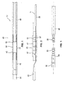
- FIGS. 1 to 3 show various components of the instrument in the disassembled state, which are in the context of the controlled from the handle 10 from bending the outer shaft 12 in the region of the shaft tip.
- Fig. 1 shows the outer shaft 12 of the instrument in the distal end portion 65 in the region of the tip without the provided in the assembled state in the outer shaft mounting parts.
- the outer shaft comprises, in the region of the tip, first and second rigid shank sections 48, 49 which are in Fig. 3 shown with further details. Between the two rigid shaft portions of the bendable portion 44 is arranged. In this case, a proximal end 45 of the region 44 is connected to the first, proximal shaft section 48 and a distal end 46 of the region 44 is connected to the second, distal shaft section 49.
- the bendable portion 44 acts as a hinge and has the function of allowing relative movement between the first and second shaft portions 48, 49 so that an angle between the first shaft portion 48 and the second shaft portion 49 can be adjusted.
- the bendable region has a tube 54 which connects the two rigid shaft sections 48, 49.
- the tube 54 is flexible.
- the tube 54 forms the outer wall of the outer shaft 12 in the region of the bendable region 44.
- the tube 54 is designed as a shrink tube, in particular as a silicone shrink tube, whereby the assembly facilitates and a gas-tight connection between the tube 54 and the two shaft portions 48, 49th is reached.
- Other mechanical connecting elements between the two shaft sections 48, 49 instead of the hose are possible.
- the proximal first shaft portion 48 is connected to the handle 10 (see Fig. 9 ).
- the first shaft portion 48 may have a profiled end 55 which is connected to the hose 54 ( Fig. 3 ).
- the second distally disposed shaft portion 49 also has a profiled end 55 for the tube 54 at the proximal end.
- a ceramic end sleeve 56 may be provided, in the region of which the ignition electrode, for example made of tungsten wire, is arranged.
- one-piece design of the two shaft portions 48, 49 may be formed in several parts and each having a support tube 50, 51, which are arranged between the tube 54 and a shaft tube.
- the support tubes 51, 50 or sleeves improve the stability of the outer shaft and are made of metal.
- the outer shaft tubes 52, 53 connected to the support tubes 51, 50 are made of plastic.
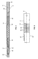
- the installation part is according to Fig. 2 in the region of the bendable area 44, as in FIG Fig. 4 shown.
- the fitting according to Fig. 2 includes the electrode 11 and a sleeve 47 surrounding the electrode.
- the sleeve 47 is made of a flexible material and has a plurality of transverse slots 57 which extend transversely to the longitudinal extent of the sleeve 47.
- the sleeve 47 may have a longitudinal slot (not shown) to further improve the flexibility and to receive the electrode in the angled state.
- the electrode 11 forms three sections.
- the first section 58 is rigid, for example, a steel wire with a diameter of about 1.5 mm. In the installed position, the first rigid portion 58 is proximal to the bendable portion 44. Distal to the rigid portion 58 is a second flexible portion 59 formed, for example, of spring steel wire having a diameter of about 0.5 mm. The second flexible portion 59 is in the installed position in the bendable portion of the shaft and allows by its flexibility a deflection of the bendable portion 44 upon actuation of the actuating mechanism on the handle 10th
- the electrode 11 is fixed.
- the fixation is achieved in that the electrode 11 is mechanically connected to the sleeve 47 and can transmit tensile and compressive forces.
- the connection of the electrode 11 with the sleeve 47 takes place at a fixing point 61 distally spaced from the proximal end 45 of the bendable portion 44.
- the fixing point 61 is in the installed position in the region of the distal end 46 of the bendable portion 44. This ensures that when moving the outer shaft, the entire length of the bendable portion 44 can be used for deflection. It is possible to displace the fixation site in the proximal or distal direction.
- connection in the region of the fixing point 61 can, as in Fig. 2 represented by a positive connection.
- Other connection types are possible.
- the electrode 11 is arcuately curved and engages in the sleeve 47 a.
- the electrode 11 forms a hook-shaped connection in the region of the fixing point 61, which is anchored to the sleeve 47. As a result, the transmission of forces is achieved safely.
- a third end portion 60 is provided, in the region of which the ignition electrode is arranged.
- This can be formed, for example, as tungsten wire with a diameter of about 0.5 mm.
- the electrode 11 is arranged axially at the proximal end or in the proximal area in a handle 10 and fixed in place.
- FIG. 4 The installation condition is in Fig. 4 shown. It can be seen that the sleeve 47 is arranged in the region of the bendable region 44 and is surrounded radially on the outside by the hose 54. A difference to the example according to Fig. 2 is the formation of the fixation 61, which in Fig. 4 has a multiple curvature for better anchorage. In contrast to the prior art is in the embodiments FIGS. 1 to 5 a relative movement between the tip of the outer shaft and the electrode for exposing the electrode not possible. Thus, the instrument is suitable according to the FIGS. 1 to 5 primarily for coagulation.
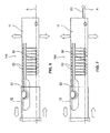
- FIG. 5 shows a further embodiment in which the electrode 11 is formed as an inner shaft 11 and has a bendable portion 144 in a distal end portion 65.
- the bendable portion 144 is formed by slits 63 formed by laser cutting in the inner shaft 11, for example.
- the slots 63 are, for example, 0.2 mm apart, the slot width being between 0.1 and 1.0 mm.
- the slots 63 are arranged overlapping.
- This overlapping area 64 between the opposing slots 63 is, for example, 0.3 to 0.8 mm, particularly preferably 0.6 mm.
- a connecting element 62 is shown, wherein the connecting element 62 is formed as a flap integral with the inner shaft 11.
- the connecting element 62 is preferably formed by laser cutting, more preferably together with the slots 63. This allows a simple and cost-effective production.
- the connecting element 62 is mechanically connected to the inner shaft 11 in the bendable area 144 or distally of the bendable area 144.
- Fig. 6 shows the under reference to Fig. 5 described embodiment of the inner shaft 11, wherein the inner shaft 11 in Fig. 6 is represented by the connecting element 62 connected to the outer shaft 12.
- connection between the inner shaft 11 and the outer shaft 12 by the connecting element 62 is such that upon a relative movement of the outer shaft 12 relative to the inner shaft 11 via the connecting element 62 a force is exerted on the inner shaft 11 such that the inner shaft 11 in the angled portion 144th its orientation changes and is deflected.
- the angling of the inner shaft 11 is preferably perpendicular to a plane defined by the axial center A of the inner shaft 11 and the overlapping regions 64. A kinking of the inner shaft 11 in this plane is prevented by the arrangement of the slots 63.
- Fig. 7 shows the case where an electrode 111 is provided in addition to the inner shaft 11. In this case, therefore, does not serve the inner shaft 11 as an electrode, as in the reference to the Fig. 5 and 6
- the inner shaft 11 encloses an electrode 111.
- the electrode 111 may be formed by various shapes. It may be in the form of a needle electrode, a spatula electrode or a sleeve, as an extension of the inner shaft 11, or another form.
- the inner shaft 11 may be formed as a contact means to the electrode. Alternatively, the electrode 111 may also extend through the entire inner shaft 11 into the handle 10 and be connected within the handle 10 to the electrical supply.
- FIG. 8 the connection of the actuating mechanism 13 with the rotary wheel 14 is shown.
- Fig. 8 and Fig. 4 belong together insofar as the continuation of the outer shaft 12 from Fig. 4 in the handle 10 according to Fig. 8 is shown.
- the mechanism for converting the torque on the handle 10 in the translational movement of the outer shaft 12 is in the FIGS. 9 to 11 explained in more detail and is in connection with the embodiment according to FIGS. 1 to 4 and 8 discloses.
- the electrode 11 is fixedly mounted in the handle 10.
- the handle 10 has connections or supply lines for the electrode, which allow the power supply and possibly the gas supply of the electrode 11.
- one or more actuating means, such as push buttons 27 are provided on the handle.
- the electrode 11 is arranged in a displaceable outer shaft 12, which protrudes beyond the handle in the distal direction and is held in the housing 26 of the handle 10 (s. Fig. 9 ).
- the outer shaft 12 is made of an insulating material and surrounds the electrode 11 at least in the area outside the handle 10th
- the outer shaft 12 is displaceable relative to the electrode 11, so that by axial movement of the outer shaft 12, the alignment of the tip of the instrument can be adjusted.
- the instrument has a braking device which permanently loads the outer shaft 12 with a braking force and acts as a displacement safeguard.
- the braking force or even self-locking of the outer shaft 12 counteracts the resistance force during insertion of the instrument into a trocar and prevents the outer shaft 12 from being displaced unintentionally in the proximal direction.
- the advantage of the displacement protection of the outer shaft 12 also comes into play in other situations, for example in the preparation.
- the braking device has a force-locking clamping element, for example in the form of a clamping ring 33 ( FIG. 11 ).
- the clamping ring 33 may be an O-ring.
- Other passive braking means that counteract the resistance in the trocar are possible.
- the clamping ring 33 is at least indirectly connected to the outer shaft 12 and transmits the introduced into the outer shaft 12 axial forces in the handle 10, specifically in the housing 26 of the handle 10.
- the outer shaft 12 is connected to a sliding sleeve 25.
- the sliding sleeve 25 and the outer shaft 12 are arranged coaxially.
- the sliding sleeve 25 can be understood as an axial extension of the outer shaft 12 in the handle 10 into it.
- the clamping ring 33 is arranged in a matching groove such that the clamping ring 33 projects beyond the outer circumference of the sliding sleeve 25.
- the clamping ring 33 is supported in the handle 10 and generates a braking force, which counteracts a force acting on the outer shaft 12 in the longitudinal direction, for example, the resistance force in the trocar counteracts.
- the sliding sleeve 25 is arranged coaxially in an inner sleeve 29 which is fixedly connected to the housing 26, in particular by a retaining plate 21.
- the clamping ring 33 presses against the inner circumference of the inner sleeve 29 and thus generates an axially acting braking force.
- the inner sleeve 29 also forms the axial guidance of the sliding sleeve 25.
- the clamping ring 33 or generally the braking device can be arranged at a different location of the sliding sleeve 25. It is also possible to use more than one clamping ring 33, for example two clamping rings.
- the actuating mechanism 13 forms a transmission gear 15 which is connected to the outer shaft 12 for transmitting the thrust.
- the actuating mechanism 13 has a rotary wheel 14 which projects at least partially out of the housing 26 of the handle 10, so that a partial circumference of the rotary wheel 14 is accessible for actuation by a finger.
- the rotational movement of the rotary wheel 14 causes the axial displacement of the outer shaft 12.
- the function of the transmission gear 15 is to convert the introduced into the rotary wheel 14 torque so that the outer shaft is subjected to an increased thrust.
- the transmission gear 15 is adapted so that the finger force for actuating the rotary wheel 14 is smaller than the self-locking of the outer shaft 12.
- the transmission gear 15 comprises the rotary wheel 14, which in turn has a drive wheel 16 and at least one driven wheel 17 connected in a rotationally fixed manner to the drive wheel 16 ( FIG. 9 ).
- the output gear 17 is formed as a gear which is coaxially connected to the drive wheel 16.
- the drive wheel 16 may have for safe movement holding means, for example in the form of a corrugation on the outer circumference. As a result, the precise movement of the drive wheel 16 is ensured by means of a finger.
- the rotary wheel 14 may be formed as a stepped wheel, wherein the drive wheel 16 and the output gear 17 are formed integrally or integrally. Alternatively, the drive wheel 16 and the output gear 17 may be mechanically connected to each other.
- an extension can be provided as a finger lever.
- the diameter of the drive wheel 16 is greater than the diameter of the output gear 17.
- the outer diameter of the drive wheel 16 is approximately 2.8 times larger than the diameter of the output gear 17.
- the lever ratio is approximately 1: 2.8.
- the required finger power is thus about 2.8 times less than the self-locking of the outer shaft 12.
- the lever ratio can be in the range of 1: 2.6-3.0, in particular in the range 1: 2.7-2.9.
- Another advantage of the transmission gear is that the displacement or the radians traveled on the outer diameter of the drive wheel 16 is also 2.8 times or a multiple of the displacement of the outer shaft 12. This allows a particularly accurate adjustment of the shaft angle can be achieved.
- the outer diameter of the drive wheel 16 is approximately 12.5 mm.
- the required for the self-locking of the sliding outer shaft 12 braking force or clamping force is about 4 Newton.
- the conversion of the torque applied by the rotary wheel 14 in a translational thrust movement of the outer shaft 12 is achieved by a carriage 18 which is axially movable in the proximal and distal directions.
- the carriage 18 forms the connection between the outer shaft 12 and the transmission gear 15.
- the carriage 18, a first rack 19, which is arranged parallel to the thrust direction of the outer shaft 12.
- the first rack 19 is toothed with the output gear 17.
- the rack 19 is arranged outside.
- an internal rack may be provided which is formed on the inside of a longitudinal slot which extends parallel to the central axis of the electrode 11.
- the output gear 17 is then arranged in the longitudinal slot.
- Fig. 9 can be seen, the carriage 18 on a second rack 20, which is arranged parallel to the first rack 19.
- the drive wheel 16 is disposed between the two racks 19 and 20 and rotatably connected to a further output gear 17.
- the further driven gear 17 (not shown) meshes with the second rack 20.
- the symmetrical structure of the actuating mechanism 13 leads to a uniform force application and to an improved safety of the instrument.
- the two toothed racks 19, 20 form two arms which extend parallel to the longitudinal axis of the electrode 11 and / or the outer shaft 12.
- the two racks 19, 20 are arranged in a linear guide, which is formed by the holding plate 21.
- the holding plate 21 is firmly seated in the housing 26 and has two parallel openings 22 for the carriage 18 ( FIG. 10 ). Through the two openings 22, the racks 19, 20 are guided, so that a secure translational movement of the carriage 18 is possible.
- the rotary wheel 14 is disposed between the two racks 19, 20 in front of the holding plate 21, whereby a compact construction of the handle 10 is achieved.
- a further improvement in safety is achieved by a locking device on the carriage 18.
- the locking device is used to fix the outer shaft 12 in a predetermined position, in particular in the position in which the outer shaft 12 and the electrode in the longitudinal direction straight, are arranged stretched.
- the locking device may comprise means which ensure a self-locking of the movable outer shaft 12. Thus, it is possible to fix different angled positions of the distal end of the instrument.
- the braking device acts in any position of the carriage 18, so that a continuous adjustment of the outer shaft 12 is possible.
- the locking device on a first locking means 23, which is arranged at the proximal end of each of the first and second rack 19, 20.
- the first locking means 23 cooperates in the locking state with a second locking means 24, which is formed on the handle 10.
- the second latching means 24 is formed on the holding plate 21 in the form of a latching recess.
- the first locking means 23 may be a correspondingly formed locking lug, which is arranged laterally on the two toothed racks 19, 20.
- the locking device improves the overall safety of the instrument. It is also possible, the locking device regardless of the transmission gear and to use the braking device, for example, when the instrument is to be used exclusively with trocars with very high resistance, such as in reusable trocars with valve flap.
- the electrode 11 can be rotated in the circumferential direction, even if the outer shaft 12 is at least partially inserted in a trocar.
- the electrode 11 and the outer shaft 12 are each arranged rotatable relative to the handle 10 about its longitudinal axis.
- the sliding sleeve 25 is provided, through which the electrode 11 is guided.
- the sliding sleeve 25 connects the outer shaft 12 and the electrode 11. It is a non-rotatable and axially movable connection.
- the sliding sleeve 25 thus allows the transmission of torque from the outer shaft 12 to the electrode 11.
- the sliding sleeve 25 and thus the outer shaft 12 connected coaxially or flush with it can be displaced in the axial direction relative to the electrode 11, which causes the bending in the region 44 allows.
- This dual function (torque transmission and axial displaceability) is achieved in that the sliding sleeve 25 at least in sections has a profiling 37 on the inner circumference.
- the electrode 11 is correspondingly profiled in the area of the profiling 37 and is in positive engagement with the sliding sleeve 25 for transmitting the torque.
- the positive connection is designed so that the sliding sleeve 25 can be moved along the electrode 11 in both the distal and in the proximal direction.
- the sliding sleeve 25 at least three sections, namely a distal sleeve portion 30, a central sleeve portion 31 and a proximal sleeve portion 32.
- the profiling 37 is formed in the region of the proximal sleeve portion 32.
- the braking device, specifically the clamping ring 33 is arranged at the proximal end of the proximal sleeve section 32.
- the profiling 37 extends over a length which corresponds approximately to the length of the two toothed racks 19, 20. This ensures that the positive connection between the electrode 11 and the profiling 37 is maintained in each relative position of the sliding sleeve 25, so that the rotation function is independent of the respective position of the outer shaft 12.
- the profiling 37 is formed in the manner of a splined shaft profile. This increases the ease of assembly, since the correspondingly profiled electrode 11 can be inserted into the sliding sleeve substantially independent of their rotational position.
- the electrode 11 has a profile section 38 with a rectangular cross-section, as in FIG Fig. 10 shown.
- the proximal and distal ends of the profile section 38 of the electrode 11 are each tapered, as in FIG Fig. 11 shown.
- the electrode Distally and proximally from the profile section 38, the electrode has a substantially circular cross section in a conventional manner.
- the cross section can change into a non-rotationally symmetrical cross section.
- the electrode may, for example, be a spade electrode.
- the middle sleeve section 31 has a shoulder 42 in the distal and proximal directions. Between the two shoulders 42, a holding portion 43 is formed, which is rotatably connected to the carriage 18. The holding portion 43 forms a recess between the two shoulders 42. In this recess, a retaining ring 28 of the carriage 18 is arranged.
- the retaining ring 28 is partially open and surrounds the sliding sleeve only partially, so that the retaining ring 28 can be easily clipped onto the sliding sleeve 25 for mounting.
- the retaining ring 28 abuts against the two shoulders 42, so that axial forces or the thrust force in the proximal and distal directions for moving the outer shaft 12 can be transmitted.
- the middle sleeve portion 31 has an annular groove 35, in which a driver 36 of the retaining ring 28 is arranged.
- the driver 36 and the annular groove 35 are rotatable relative to each other, so that the sleeve 25 is freely rotatable in the retaining ring 28.
- the driver 36 also transmits the thrust in both axial directions.
- the retaining ring 28 is disposed between the two racks 19, 20 at its distal end. Specifically, a cross member 41 is provided, which connects the distal ends of the two racks 19, 20, as in Fig. 9 shown.
- the traverse 41 in turn is fixedly connected to the retaining ring 28 or integrally formed.
- the crossbar 41 and the retaining ring 28 can also be regarded as a traverse with two holding jaws arranged at the bottom, which surround the sliding sleeve 25 in part.
- the sliding sleeve 25 further includes a distal sleeve portion 30.
- the distal sleeve portion 30 is rotatably connected to the outer shaft 12.
- the connection can be made mechanically, for example by a fastening sleeve 34, which is arranged in the outer shaft 12 and crimped at the proximal end of the outer shaft 12 with the sliding sleeve 25.
- Other mounting options are conceivable.
- the distal sleeve portion 30 forms, together with the housing 26, an axial stop which determines the maximum extension position of the outer shaft 12.
- the inner sleeve 29 is coaxial with the electrode 11 and extends distally and proximally from the retaining plate 21, as in FIGS Figures 9 . 11 shown.
- the inner sleeve 29 forms a sleeve portion 39 with two guide webs 40, which extend parallel to the central axis of the inner sleeve 29.
- the guide webs 40 form bearing surfaces for the two racks 19, 20 and thus improve the stability of the linear guide.
- a portion of the peripheral wall of the inner sleeve 29 is removed in the region of the rotary wheel 14 to provide space for the rotary wheel 14, which is arranged in the housing 26 except for the required for the finger actuation circumferential segment without colliding with the inner sleeve 29. This contributes to a compact construction of the handle.
- the rotational function of the handle makes it suitable for the positioning of the angled electrode 11, so that the handle is not only particularly safe and inexpensive, but is easy to use.
- the instrument combines three functions:
- the stem tip and the third portion of the electrode is angled from the handle, so that the angle of the stem tip and the electrode can be changed in use.
- the outer shaft and thus the electrode are rotatable about their longitudinal axis, so that the electrode can be aligned, which is advantageous in non-rotationally symmetrical electrodes or to change the application position.
- the braking device prevents unwanted changes in position of the shaft tip, for example.
- the instrument according to the invention is additionally disclosed and claimed in connection with an electrosurgical unit, in particular for use on biological tissue, for example for argon plasma coagulation.
Landscapes
- Health & Medical Sciences (AREA)
- Surgery (AREA)
- Life Sciences & Earth Sciences (AREA)
- Engineering & Computer Science (AREA)
- Molecular Biology (AREA)
- Public Health (AREA)
- Heart & Thoracic Surgery (AREA)
- Medical Informatics (AREA)
- Nuclear Medicine, Radiotherapy & Molecular Imaging (AREA)
- Animal Behavior & Ethology (AREA)
- General Health & Medical Sciences (AREA)
- Biomedical Technology (AREA)
- Veterinary Medicine (AREA)
- Physics & Mathematics (AREA)
- Plasma & Fusion (AREA)
- Otolaryngology (AREA)
- Cardiology (AREA)
- Surgical Instruments (AREA)
Priority Applications (8)
| Application Number | Priority Date | Filing Date | Title |
|---|---|---|---|
| PL15167061T PL3092966T3 (pl) | 2015-05-11 | 2015-05-11 | Instrument elektrochirurgiczny |
| EP15167061.9A EP3092966B1 (fr) | 2015-05-11 | 2015-05-11 | Instrument électrochirurgical |
| BR102016009917-0A BR102016009917B1 (pt) | 2015-05-11 | 2016-05-03 | Instrumento eletrocirúrgico e equipamento eletrocirúrgico para uma utilização em tecido biológico |
| US15/147,587 US10751106B2 (en) | 2015-05-11 | 2016-05-05 | Electrosurgical instrument and device with such an instrument |
| KR1020160056195A KR102201450B1 (ko) | 2015-05-11 | 2016-05-09 | 전기 외과 도구 및 이러한 도구를 구비한 디바이스 |
| RU2016118137A RU2703501C2 (ru) | 2015-05-11 | 2016-05-10 | Электрохирургический инструмент и электрохирургический аппарат для применения на биологической ткани |
| CN201610312082.2A CN106137383B (zh) | 2015-05-11 | 2016-05-11 | 电外科器械和具有这种器械的设备 |
| JP2016095686A JP6684148B2 (ja) | 2015-05-11 | 2016-05-11 | 電気手術器具及びその器具を備える装置 |
Applications Claiming Priority (1)
| Application Number | Priority Date | Filing Date | Title |
|---|---|---|---|
| EP15167061.9A EP3092966B1 (fr) | 2015-05-11 | 2015-05-11 | Instrument électrochirurgical |
Publications (2)
| Publication Number | Publication Date |
|---|---|
| EP3092966A1 true EP3092966A1 (fr) | 2016-11-16 |
| EP3092966B1 EP3092966B1 (fr) | 2021-01-20 |
Family
ID=53174844
Family Applications (1)
| Application Number | Title | Priority Date | Filing Date |
|---|---|---|---|
| EP15167061.9A Not-in-force EP3092966B1 (fr) | 2015-05-11 | 2015-05-11 | Instrument électrochirurgical |
Country Status (8)
| Country | Link |
|---|---|
| US (1) | US10751106B2 (fr) |
| EP (1) | EP3092966B1 (fr) |
| JP (1) | JP6684148B2 (fr) |
| KR (1) | KR102201450B1 (fr) |
| CN (1) | CN106137383B (fr) |
| BR (1) | BR102016009917B1 (fr) |
| PL (1) | PL3092966T3 (fr) |
| RU (1) | RU2703501C2 (fr) |
Cited By (1)
| Publication number | Priority date | Publication date | Assignee | Title |
|---|---|---|---|---|
| CN110934638A (zh) * | 2019-11-20 | 2020-03-31 | 河北省胸科医院 | 一种可弯曲电刀手柄、电刀及可弯曲电刀手柄的调整方法 |
Families Citing this family (9)
| Publication number | Priority date | Publication date | Assignee | Title |
|---|---|---|---|---|
| US9060765B2 (en) | 2010-11-08 | 2015-06-23 | Bovie Medical Corporation | Electrosurgical apparatus with retractable blade |
| GB201621748D0 (en) * | 2016-12-20 | 2017-02-01 | Gyrus Medical Ltd | Electrosurgical apparatus |
| BR112019015648A2 (pt) | 2017-01-30 | 2020-03-31 | Apyx Medical Corporation | Aparelho eletrocirúrgico com eixo flexível |
| EP3629968B1 (fr) | 2017-05-30 | 2024-11-20 | Apyx Medical Corporation | Appareil électrochirurgical avec pointe robotisée |
| BR112022017043A2 (pt) | 2020-02-26 | 2022-11-16 | Apyx Medical Corp | Aparelho eletrocirúrgico com haste flexível |
| CN111658130A (zh) * | 2020-07-09 | 2020-09-15 | 福建医科大学附属协和医院 | 一种电凝钩 |
| CN114001712B (zh) * | 2021-12-24 | 2022-03-22 | 四川公路工程咨询监理有限公司 | 危岩体变形监测装置及预警系统 |
| CN115363697B (zh) * | 2022-08-31 | 2025-09-19 | 精勤智造(苏州)医疗科技有限公司 | 一种微创手术钳 |
| CN120477929B (zh) * | 2025-06-17 | 2026-04-07 | 安徽贝科邦生物科技有限公司 | 带有液体通道的可弯曲电极及其系统 |
Citations (7)
| Publication number | Priority date | Publication date | Assignee | Title |
|---|---|---|---|---|
| DE4414810C1 (de) * | 1994-04-28 | 1995-08-10 | Ep Flex Feinwerktechnik Gmbh | Endoskoprohrsystem mit einem Zugfederband und einem Stabilisierungsfederband |
| US20080051802A1 (en) * | 2006-08-10 | 2008-02-28 | Novineon Healthcare Technology Partners Gmbh | Medical instrument |
| US20080200761A1 (en) * | 2005-09-20 | 2008-08-21 | Ai Medical Devices | Endotracheal intubation device |
| US20090125023A1 (en) | 2007-11-13 | 2009-05-14 | Cytyc Corporation | Electrosurgical Instrument |
| US20100211076A1 (en) * | 2008-10-13 | 2010-08-19 | Dfine, Inc. | Systems for treating a vertebral body |
| US20150073341A1 (en) * | 2009-06-24 | 2015-03-12 | Amr Salahieh | Steerable delivery sheaths |
| US20150119851A1 (en) * | 2013-10-30 | 2015-04-30 | Nordson Corporation | Instrument and method for delivery, deployment, and tamponade of hemostats and methods of assembling an instrument therefor |
Family Cites Families (12)
| Publication number | Priority date | Publication date | Assignee | Title |
|---|---|---|---|---|
| SU466022A1 (ru) | 1972-03-16 | 1975-04-05 | Научно-Исследовательский Институт Клинической И Экспериментальной Хирургии | Устройство дл внутриполостной коагул ции |
| US5295614A (en) * | 1992-12-22 | 1994-03-22 | Chang Peter J Y | Double reduction gear for dispensing gun |
| DE4323584A1 (de) * | 1993-07-14 | 1995-01-19 | Delma Elektro Med App | Zerlegbares medizinisches Instrument |
| EP0915682B1 (fr) * | 1996-07-04 | 2003-10-01 | Erbe Elektromedizin GmbH | Electrode chirurgicale deplacable axialement, assistee par un gaz |
| EP1435867B1 (fr) * | 2001-09-05 | 2010-11-17 | Salient Surgical Technologies, Inc. | Dispositifs et systemes medicaux utilisant un liquide |
| US7758625B2 (en) | 2003-09-12 | 2010-07-20 | Abbott Vascular Solutions Inc. | Delivery system for medical devices |
| US8057508B2 (en) * | 2004-07-28 | 2011-11-15 | Ethicon Endo-Surgery, Inc. | Surgical instrument incorporating an electrically actuated articulation locking mechanism |
| RU2299036C2 (ru) | 2005-05-23 | 2007-05-20 | Северный государственный медицинский университет (СГМУ) | Эндохирургический инструмент с меняющейся осью |
| US20080311345A1 (en) | 2006-02-23 | 2008-12-18 | Picodeon Ltd Oy | Coating With Carbon Nitride and Carbon Nitride Coated Product |
| US8343035B2 (en) * | 2009-04-20 | 2013-01-01 | Spine View, Inc. | Dilator with direct visualization |
| US9402682B2 (en) | 2010-09-24 | 2016-08-02 | Ethicon Endo-Surgery, Llc | Articulation joint features for articulating surgical device |
| GB2508905A (en) * | 2012-12-14 | 2014-06-18 | Gyrus Medical Ltd | Endoscopic instrument with bypass lead |
-
2015
- 2015-05-11 EP EP15167061.9A patent/EP3092966B1/fr not_active Not-in-force
- 2015-05-11 PL PL15167061T patent/PL3092966T3/pl unknown
-
2016
- 2016-05-03 BR BR102016009917-0A patent/BR102016009917B1/pt not_active IP Right Cessation
- 2016-05-05 US US15/147,587 patent/US10751106B2/en not_active Expired - Fee Related
- 2016-05-09 KR KR1020160056195A patent/KR102201450B1/ko not_active Expired - Fee Related
- 2016-05-10 RU RU2016118137A patent/RU2703501C2/ru active
- 2016-05-11 JP JP2016095686A patent/JP6684148B2/ja not_active Expired - Fee Related
- 2016-05-11 CN CN201610312082.2A patent/CN106137383B/zh not_active Expired - Fee Related
Patent Citations (7)
| Publication number | Priority date | Publication date | Assignee | Title |
|---|---|---|---|---|
| DE4414810C1 (de) * | 1994-04-28 | 1995-08-10 | Ep Flex Feinwerktechnik Gmbh | Endoskoprohrsystem mit einem Zugfederband und einem Stabilisierungsfederband |
| US20080200761A1 (en) * | 2005-09-20 | 2008-08-21 | Ai Medical Devices | Endotracheal intubation device |
| US20080051802A1 (en) * | 2006-08-10 | 2008-02-28 | Novineon Healthcare Technology Partners Gmbh | Medical instrument |
| US20090125023A1 (en) | 2007-11-13 | 2009-05-14 | Cytyc Corporation | Electrosurgical Instrument |
| US20100211076A1 (en) * | 2008-10-13 | 2010-08-19 | Dfine, Inc. | Systems for treating a vertebral body |
| US20150073341A1 (en) * | 2009-06-24 | 2015-03-12 | Amr Salahieh | Steerable delivery sheaths |
| US20150119851A1 (en) * | 2013-10-30 | 2015-04-30 | Nordson Corporation | Instrument and method for delivery, deployment, and tamponade of hemostats and methods of assembling an instrument therefor |
Cited By (1)
| Publication number | Priority date | Publication date | Assignee | Title |
|---|---|---|---|---|
| CN110934638A (zh) * | 2019-11-20 | 2020-03-31 | 河北省胸科医院 | 一种可弯曲电刀手柄、电刀及可弯曲电刀手柄的调整方法 |
Also Published As
| Publication number | Publication date |
|---|---|
| US10751106B2 (en) | 2020-08-25 |
| RU2016118137A (ru) | 2017-11-15 |
| RU2703501C2 (ru) | 2019-10-17 |
| BR102016009917A2 (pt) | 2016-11-16 |
| CN106137383B (zh) | 2021-09-07 |
| PL3092966T3 (pl) | 2021-05-17 |
| JP2016209594A (ja) | 2016-12-15 |
| US20160331438A1 (en) | 2016-11-17 |
| EP3092966B1 (fr) | 2021-01-20 |
| JP6684148B2 (ja) | 2020-04-22 |
| RU2016118137A3 (fr) | 2019-05-23 |
| CN106137383A (zh) | 2016-11-23 |
| BR102016009917B1 (pt) | 2022-09-27 |
| KR102201450B1 (ko) | 2021-01-13 |
| KR20160132770A (ko) | 2016-11-21 |
Similar Documents
| Publication | Publication Date | Title |
|---|---|---|
| EP3092966B1 (fr) | Instrument électrochirurgical | |
| EP2510887B1 (fr) | Outil pour un instrument de chirurgie micro-invasive | |
| EP1151723B1 (fr) | Dispositif chirurgical, notamment du type pince ou du type pincette | |
| EP2696741B1 (fr) | Dispositif de commande | |
| EP2653120B1 (fr) | Dispositif de manipulation pour un instrument médical | |
| DE102017100294A1 (de) | Elektrochirurgische Vorrichtung | |
| EP2014246B1 (fr) | Instrument médical | |
| DE10031773A1 (de) | Chirurgisches Instrument,insbesondere Pinzette oder Zange | |
| EP2904983B1 (fr) | Instrument électrochirurgical avec un actionneur rotatif et avec un dispositif de freinage or de blocage | |
| DE4341735C1 (de) | Chirurgisches Rohrschaftinstrument | |
| EP2489315A1 (fr) | Instrument médical | |
| WO2011079897A1 (fr) | Commande d'une tige tubulaire d'un instrument chirurgical | |
| EP2653118A1 (fr) | Instrument médical micro-invasif | |
| EP2653119B1 (fr) | Instrument médical et procédé d'assemblage d'un instrument médical | |
| EP2653123A1 (fr) | Outil pour un instrument médical | |
| EP2464302A1 (fr) | Instrument électrochirurgical | |
| WO2003013378A1 (fr) | Electrode pour resectoscopes urologiques | |
| EP3179931B1 (fr) | Instrument medical pour la chirurgie endoscopique | |
| EP3448293B1 (fr) | Accouplement d'un instrument chirurgical hf endoscopique et instrument chirurgical hf muni d'un tel accouplement | |
| DE10328515B4 (de) | Chirurgisches Instrument | |
| EP3747377A1 (fr) | Instrument chirurgical destiné à la chirurgie mini-invasive | |
| DE20309776U1 (de) | Chirurgisches Instrument | |
| EP1788960B1 (fr) | Instrument medical de coupe et/ou de maintien | |
| EP1635716B1 (fr) | Instrument chirurgical | |
| WO2016124318A1 (fr) | Pince chirurgicale comprenant une partie formant mâchoire réalisée en deux parties |
Legal Events
| Date | Code | Title | Description |
|---|---|---|---|
| PUAI | Public reference made under article 153(3) epc to a published international application that has entered the european phase |
Free format text: ORIGINAL CODE: 0009012 |
|
| 17P | Request for examination filed |
Effective date: 20150511 |
|
| AK | Designated contracting states |
Kind code of ref document: A1 Designated state(s): AL AT BE BG CH CY CZ DE DK EE ES FI FR GB GR HR HU IE IS IT LI LT LU LV MC MK MT NL NO PL PT RO RS SE SI SK SM TR |
|
| AX | Request for extension of the european patent |
Extension state: BA ME |
|
| RAP1 | Party data changed (applicant data changed or rights of an application transferred) |
Owner name: ERBE ELEKTROMEDIZIN GMBH |
|
| STAA | Information on the status of an ep patent application or granted ep patent |
Free format text: STATUS: EXAMINATION IS IN PROGRESS |
|
| 17Q | First examination report despatched |
Effective date: 20190509 |
|
| GRAP | Despatch of communication of intention to grant a patent |
Free format text: ORIGINAL CODE: EPIDOSNIGR1 |
|
| STAA | Information on the status of an ep patent application or granted ep patent |
Free format text: STATUS: GRANT OF PATENT IS INTENDED |
|
| INTG | Intention to grant announced |
Effective date: 20200225 |
|
| GRAJ | Information related to disapproval of communication of intention to grant by the applicant or resumption of examination proceedings by the epo deleted |
Free format text: ORIGINAL CODE: EPIDOSDIGR1 |
|
| STAA | Information on the status of an ep patent application or granted ep patent |
Free format text: STATUS: EXAMINATION IS IN PROGRESS |
|
| GRAP | Despatch of communication of intention to grant a patent |
Free format text: ORIGINAL CODE: EPIDOSNIGR1 |
|
| STAA | Information on the status of an ep patent application or granted ep patent |
Free format text: STATUS: GRANT OF PATENT IS INTENDED |
|
| INTC | Intention to grant announced (deleted) | ||
| INTG | Intention to grant announced |
Effective date: 20200617 |
|
| GRAJ | Information related to disapproval of communication of intention to grant by the applicant or resumption of examination proceedings by the epo deleted |
Free format text: ORIGINAL CODE: EPIDOSDIGR1 |
|
| GRAP | Despatch of communication of intention to grant a patent |
Free format text: ORIGINAL CODE: EPIDOSNIGR1 |
|
| INTG | Intention to grant announced |
Effective date: 20200730 |
|
| GRAS | Grant fee paid |
Free format text: ORIGINAL CODE: EPIDOSNIGR3 |
|
| GRAA | (expected) grant |
Free format text: ORIGINAL CODE: 0009210 |
|
| STAA | Information on the status of an ep patent application or granted ep patent |
Free format text: STATUS: THE PATENT HAS BEEN GRANTED |
|
| AK | Designated contracting states |
Kind code of ref document: B1 Designated state(s): AL AT BE BG CH CY CZ DE DK EE ES FI FR GB GR HR HU IE IS IT LI LT LU LV MC MK MT NL NO PL PT RO RS SE SI SK SM TR |
|
| REG | Reference to a national code |
Ref country code: GB Ref legal event code: FG4D Free format text: NOT ENGLISH |
|
| REG | Reference to a national code |
Ref country code: CH Ref legal event code: EP |
|
| REG | Reference to a national code |
Ref country code: DE Ref legal event code: R096 Ref document number: 502015014167 Country of ref document: DE |
|
| REG | Reference to a national code |
Ref country code: AT Ref legal event code: REF Ref document number: 1355677 Country of ref document: AT Kind code of ref document: T Effective date: 20210215 |
|
| REG | Reference to a national code |
Ref country code: IE Ref legal event code: FG4D Free format text: LANGUAGE OF EP DOCUMENT: GERMAN |
|
| REG | Reference to a national code |
Ref country code: NL Ref legal event code: MP Effective date: 20210120 |
|
| REG | Reference to a national code |
Ref country code: LT Ref legal event code: MG9D |
|
| PG25 | Lapsed in a contracting state [announced via postgrant information from national office to epo] |
Ref country code: HR Free format text: LAPSE BECAUSE OF FAILURE TO SUBMIT A TRANSLATION OF THE DESCRIPTION OR TO PAY THE FEE WITHIN THE PRESCRIBED TIME-LIMIT Effective date: 20210120 Ref country code: FI Free format text: LAPSE BECAUSE OF FAILURE TO SUBMIT A TRANSLATION OF THE DESCRIPTION OR TO PAY THE FEE WITHIN THE PRESCRIBED TIME-LIMIT Effective date: 20210120 Ref country code: GR Free format text: LAPSE BECAUSE OF FAILURE TO SUBMIT A TRANSLATION OF THE DESCRIPTION OR TO PAY THE FEE WITHIN THE PRESCRIBED TIME-LIMIT Effective date: 20210421 Ref country code: PT Free format text: LAPSE BECAUSE OF FAILURE TO SUBMIT A TRANSLATION OF THE DESCRIPTION OR TO PAY THE FEE WITHIN THE PRESCRIBED TIME-LIMIT Effective date: 20210520 Ref country code: LT Free format text: LAPSE BECAUSE OF FAILURE TO SUBMIT A TRANSLATION OF THE DESCRIPTION OR TO PAY THE FEE WITHIN THE PRESCRIBED TIME-LIMIT Effective date: 20210120 Ref country code: BG Free format text: LAPSE BECAUSE OF FAILURE TO SUBMIT A TRANSLATION OF THE DESCRIPTION OR TO PAY THE FEE WITHIN THE PRESCRIBED TIME-LIMIT Effective date: 20210420 Ref country code: NO Free format text: LAPSE BECAUSE OF FAILURE TO SUBMIT A TRANSLATION OF THE DESCRIPTION OR TO PAY THE FEE WITHIN THE PRESCRIBED TIME-LIMIT Effective date: 20210420 Ref country code: NL Free format text: LAPSE BECAUSE OF FAILURE TO SUBMIT A TRANSLATION OF THE DESCRIPTION OR TO PAY THE FEE WITHIN THE PRESCRIBED TIME-LIMIT Effective date: 20210120 |
|
| PG25 | Lapsed in a contracting state [announced via postgrant information from national office to epo] |
Ref country code: LV Free format text: LAPSE BECAUSE OF FAILURE TO SUBMIT A TRANSLATION OF THE DESCRIPTION OR TO PAY THE FEE WITHIN THE PRESCRIBED TIME-LIMIT Effective date: 20210120 Ref country code: RS Free format text: LAPSE BECAUSE OF FAILURE TO SUBMIT A TRANSLATION OF THE DESCRIPTION OR TO PAY THE FEE WITHIN THE PRESCRIBED TIME-LIMIT Effective date: 20210120 Ref country code: SE Free format text: LAPSE BECAUSE OF FAILURE TO SUBMIT A TRANSLATION OF THE DESCRIPTION OR TO PAY THE FEE WITHIN THE PRESCRIBED TIME-LIMIT Effective date: 20210120 |
|
| PG25 | Lapsed in a contracting state [announced via postgrant information from national office to epo] |
Ref country code: IS Free format text: LAPSE BECAUSE OF FAILURE TO SUBMIT A TRANSLATION OF THE DESCRIPTION OR TO PAY THE FEE WITHIN THE PRESCRIBED TIME-LIMIT Effective date: 20210520 |
|
| REG | Reference to a national code |
Ref country code: DE Ref legal event code: R097 Ref document number: 502015014167 Country of ref document: DE |
|
| PG25 | Lapsed in a contracting state [announced via postgrant information from national office to epo] |
Ref country code: CZ Free format text: LAPSE BECAUSE OF FAILURE TO SUBMIT A TRANSLATION OF THE DESCRIPTION OR TO PAY THE FEE WITHIN THE PRESCRIBED TIME-LIMIT Effective date: 20210120 Ref country code: EE Free format text: LAPSE BECAUSE OF FAILURE TO SUBMIT A TRANSLATION OF THE DESCRIPTION OR TO PAY THE FEE WITHIN THE PRESCRIBED TIME-LIMIT Effective date: 20210120 Ref country code: SM Free format text: LAPSE BECAUSE OF FAILURE TO SUBMIT A TRANSLATION OF THE DESCRIPTION OR TO PAY THE FEE WITHIN THE PRESCRIBED TIME-LIMIT Effective date: 20210120 |
|
| PLBE | No opposition filed within time limit |
Free format text: ORIGINAL CODE: 0009261 |
|
| STAA | Information on the status of an ep patent application or granted ep patent |
Free format text: STATUS: NO OPPOSITION FILED WITHIN TIME LIMIT |
|
| PG25 | Lapsed in a contracting state [announced via postgrant information from national office to epo] |
Ref country code: DK Free format text: LAPSE BECAUSE OF FAILURE TO SUBMIT A TRANSLATION OF THE DESCRIPTION OR TO PAY THE FEE WITHIN THE PRESCRIBED TIME-LIMIT Effective date: 20210120 Ref country code: ES Free format text: LAPSE BECAUSE OF FAILURE TO SUBMIT A TRANSLATION OF THE DESCRIPTION OR TO PAY THE FEE WITHIN THE PRESCRIBED TIME-LIMIT Effective date: 20210120 Ref country code: SK Free format text: LAPSE BECAUSE OF FAILURE TO SUBMIT A TRANSLATION OF THE DESCRIPTION OR TO PAY THE FEE WITHIN THE PRESCRIBED TIME-LIMIT Effective date: 20210120 Ref country code: RO Free format text: LAPSE BECAUSE OF FAILURE TO SUBMIT A TRANSLATION OF THE DESCRIPTION OR TO PAY THE FEE WITHIN THE PRESCRIBED TIME-LIMIT Effective date: 20210120 |
|
| 26N | No opposition filed |
Effective date: 20211021 |
|
| REG | Reference to a national code |
Ref country code: CH Ref legal event code: PL |
|
| PG25 | Lapsed in a contracting state [announced via postgrant information from national office to epo] |
Ref country code: CH Free format text: LAPSE BECAUSE OF NON-PAYMENT OF DUE FEES Effective date: 20210531 Ref country code: AL Free format text: LAPSE BECAUSE OF FAILURE TO SUBMIT A TRANSLATION OF THE DESCRIPTION OR TO PAY THE FEE WITHIN THE PRESCRIBED TIME-LIMIT Effective date: 20210120 Ref country code: MC Free format text: LAPSE BECAUSE OF FAILURE TO SUBMIT A TRANSLATION OF THE DESCRIPTION OR TO PAY THE FEE WITHIN THE PRESCRIBED TIME-LIMIT Effective date: 20210120 Ref country code: LI Free format text: LAPSE BECAUSE OF NON-PAYMENT OF DUE FEES Effective date: 20210531 Ref country code: LU Free format text: LAPSE BECAUSE OF NON-PAYMENT OF DUE FEES Effective date: 20210511 |
|
| REG | Reference to a national code |
Ref country code: BE Ref legal event code: MM Effective date: 20210531 |
|
| PG25 | Lapsed in a contracting state [announced via postgrant information from national office to epo] |
Ref country code: SI Free format text: LAPSE BECAUSE OF FAILURE TO SUBMIT A TRANSLATION OF THE DESCRIPTION OR TO PAY THE FEE WITHIN THE PRESCRIBED TIME-LIMIT Effective date: 20210120 |
|
| PG25 | Lapsed in a contracting state [announced via postgrant information from national office to epo] |
Ref country code: IE Free format text: LAPSE BECAUSE OF NON-PAYMENT OF DUE FEES Effective date: 20210511 |
|
| PG25 | Lapsed in a contracting state [announced via postgrant information from national office to epo] |
Ref country code: IS Free format text: LAPSE BECAUSE OF FAILURE TO SUBMIT A TRANSLATION OF THE DESCRIPTION OR TO PAY THE FEE WITHIN THE PRESCRIBED TIME-LIMIT Effective date: 20210520 |
|
| REG | Reference to a national code |
Ref country code: AT Ref legal event code: MM01 Ref document number: 1355677 Country of ref document: AT Kind code of ref document: T Effective date: 20210511 |
|
| PG25 | Lapsed in a contracting state [announced via postgrant information from national office to epo] |
Ref country code: BE Free format text: LAPSE BECAUSE OF NON-PAYMENT OF DUE FEES Effective date: 20210531 |
|
| PGFP | Annual fee paid to national office [announced via postgrant information from national office to epo] |
Ref country code: IT Payment date: 20220519 Year of fee payment: 8 Ref country code: GB Payment date: 20220524 Year of fee payment: 8 Ref country code: FR Payment date: 20220526 Year of fee payment: 8 Ref country code: DE Payment date: 20220527 Year of fee payment: 8 |
|
| PG25 | Lapsed in a contracting state [announced via postgrant information from national office to epo] |
Ref country code: AT Free format text: LAPSE BECAUSE OF NON-PAYMENT OF DUE FEES Effective date: 20210511 |
|
| PGFP | Annual fee paid to national office [announced via postgrant information from national office to epo] |
Ref country code: PL Payment date: 20220415 Year of fee payment: 8 |
|
| PG25 | Lapsed in a contracting state [announced via postgrant information from national office to epo] |
Ref country code: HU Free format text: LAPSE BECAUSE OF FAILURE TO SUBMIT A TRANSLATION OF THE DESCRIPTION OR TO PAY THE FEE WITHIN THE PRESCRIBED TIME-LIMIT; INVALID AB INITIO Effective date: 20150511 |
|
| PG25 | Lapsed in a contracting state [announced via postgrant information from national office to epo] |
Ref country code: CY Free format text: LAPSE BECAUSE OF FAILURE TO SUBMIT A TRANSLATION OF THE DESCRIPTION OR TO PAY THE FEE WITHIN THE PRESCRIBED TIME-LIMIT Effective date: 20210120 |
|
| REG | Reference to a national code |
Ref country code: DE Ref legal event code: R119 Ref document number: 502015014167 Country of ref document: DE |
|
| GBPC | Gb: european patent ceased through non-payment of renewal fee |
Effective date: 20230511 |
|
| PG25 | Lapsed in a contracting state [announced via postgrant information from national office to epo] |
Ref country code: MK Free format text: LAPSE BECAUSE OF FAILURE TO SUBMIT A TRANSLATION OF THE DESCRIPTION OR TO PAY THE FEE WITHIN THE PRESCRIBED TIME-LIMIT Effective date: 20210120 Ref country code: IT Free format text: LAPSE BECAUSE OF NON-PAYMENT OF DUE FEES Effective date: 20230511 Ref country code: DE Free format text: LAPSE BECAUSE OF NON-PAYMENT OF DUE FEES Effective date: 20231201 Ref country code: GB Free format text: LAPSE BECAUSE OF NON-PAYMENT OF DUE FEES Effective date: 20230511 |
|
| PG25 | Lapsed in a contracting state [announced via postgrant information from national office to epo] |
Ref country code: FR Free format text: LAPSE BECAUSE OF NON-PAYMENT OF DUE FEES Effective date: 20230531 |
|
| PG25 | Lapsed in a contracting state [announced via postgrant information from national office to epo] |
Ref country code: MT Free format text: LAPSE BECAUSE OF FAILURE TO SUBMIT A TRANSLATION OF THE DESCRIPTION OR TO PAY THE FEE WITHIN THE PRESCRIBED TIME-LIMIT Effective date: 20210120 |
|
| PG25 | Lapsed in a contracting state [announced via postgrant information from national office to epo] |
Ref country code: PL Free format text: LAPSE BECAUSE OF NON-PAYMENT OF DUE FEES Effective date: 20230511 |
|
| PG25 | Lapsed in a contracting state [announced via postgrant information from national office to epo] |
Ref country code: PL Free format text: LAPSE BECAUSE OF NON-PAYMENT OF DUE FEES Effective date: 20230511 |
|
| PG25 | Lapsed in a contracting state [announced via postgrant information from national office to epo] |
Ref country code: TR Free format text: LAPSE BECAUSE OF FAILURE TO SUBMIT A TRANSLATION OF THE DESCRIPTION OR TO PAY THE FEE WITHIN THE PRESCRIBED TIME-LIMIT Effective date: 20210120 |