EP3094896B1 - Ensemble vanne - Google Patents
Ensemble vanne Download PDFInfo
- Publication number
- EP3094896B1 EP3094896B1 EP15702827.5A EP15702827A EP3094896B1 EP 3094896 B1 EP3094896 B1 EP 3094896B1 EP 15702827 A EP15702827 A EP 15702827A EP 3094896 B1 EP3094896 B1 EP 3094896B1
- Authority
- EP
- European Patent Office
- Prior art keywords
- valve
- chamber
- valve chamber
- seal member
- fuel cartridge
- Prior art date
- Legal status (The legal status is an assumption and is not a legal conclusion. Google has not performed a legal analysis and makes no representation as to the accuracy of the status listed.)
- Not-in-force
Links
- 239000000446 fuel Substances 0.000 claims description 34
- UFHFLCQGNIYNRP-UHFFFAOYSA-N Hydrogen Chemical compound [H][H] UFHFLCQGNIYNRP-UHFFFAOYSA-N 0.000 claims description 21
- 239000001257 hydrogen Substances 0.000 claims description 19
- 229910052739 hydrogen Inorganic materials 0.000 claims description 19
- 230000000712 assembly Effects 0.000 claims description 12
- 238000000429 assembly Methods 0.000 claims description 12
- 239000012530 fluid Substances 0.000 claims description 10
- 230000007704 transition Effects 0.000 claims description 10
- 230000003247 decreasing effect Effects 0.000 claims description 3
- 238000009434 installation Methods 0.000 claims description 2
- 238000007789 sealing Methods 0.000 description 11
- 230000006835 compression Effects 0.000 description 3
- 238000007906 compression Methods 0.000 description 3
- 238000006073 displacement reaction Methods 0.000 description 2
- 238000005553 drilling Methods 0.000 description 2
- 238000004519 manufacturing process Methods 0.000 description 2
- 238000003825 pressing Methods 0.000 description 2
- 238000005520 cutting process Methods 0.000 description 1
- 238000003780 insertion Methods 0.000 description 1
- 230000037431 insertion Effects 0.000 description 1
- 238000003754 machining Methods 0.000 description 1
- 230000014759 maintenance of location Effects 0.000 description 1
- 230000002028 premature Effects 0.000 description 1
- 150000003384 small molecules Chemical class 0.000 description 1
- 238000003860 storage Methods 0.000 description 1
Images



Classifications
-
- F—MECHANICAL ENGINEERING; LIGHTING; HEATING; WEAPONS; BLASTING
- F16—ENGINEERING ELEMENTS AND UNITS; GENERAL MEASURES FOR PRODUCING AND MAINTAINING EFFECTIVE FUNCTIONING OF MACHINES OR INSTALLATIONS; THERMAL INSULATION IN GENERAL
- F16K—VALVES; TAPS; COCKS; ACTUATING-FLOATS; DEVICES FOR VENTING OR AERATING
- F16K1/00—Lift valves or globe valves, i.e. cut-off apparatus with closure members having at least a component of their opening and closing motion perpendicular to the closing faces
- F16K1/32—Details
- F16K1/34—Cutting-off parts, e.g. valve members, seats
- F16K1/36—Valve members
-
- F—MECHANICAL ENGINEERING; LIGHTING; HEATING; WEAPONS; BLASTING
- F16—ENGINEERING ELEMENTS AND UNITS; GENERAL MEASURES FOR PRODUCING AND MAINTAINING EFFECTIVE FUNCTIONING OF MACHINES OR INSTALLATIONS; THERMAL INSULATION IN GENERAL
- F16K—VALVES; TAPS; COCKS; ACTUATING-FLOATS; DEVICES FOR VENTING OR AERATING
- F16K1/00—Lift valves or globe valves, i.e. cut-off apparatus with closure members having at least a component of their opening and closing motion perpendicular to the closing faces
- F16K1/12—Lift valves or globe valves, i.e. cut-off apparatus with closure members having at least a component of their opening and closing motion perpendicular to the closing faces with streamlined valve member around which the fluid flows when the valve is opened
-
- F—MECHANICAL ENGINEERING; LIGHTING; HEATING; WEAPONS; BLASTING
- F16—ENGINEERING ELEMENTS AND UNITS; GENERAL MEASURES FOR PRODUCING AND MAINTAINING EFFECTIVE FUNCTIONING OF MACHINES OR INSTALLATIONS; THERMAL INSULATION IN GENERAL
- F16K—VALVES; TAPS; COCKS; ACTUATING-FLOATS; DEVICES FOR VENTING OR AERATING
- F16K1/00—Lift valves or globe valves, i.e. cut-off apparatus with closure members having at least a component of their opening and closing motion perpendicular to the closing faces
- F16K1/32—Details
- F16K1/34—Cutting-off parts, e.g. valve members, seats
- F16K1/46—Attachment of sealing rings
-
- F—MECHANICAL ENGINEERING; LIGHTING; HEATING; WEAPONS; BLASTING
- F17—STORING OR DISTRIBUTING GASES OR LIQUIDS
- F17C—VESSELS FOR CONTAINING OR STORING COMPRESSED, LIQUEFIED OR SOLIDIFIED GASES; FIXED-CAPACITY GAS-HOLDERS; FILLING VESSELS WITH, OR DISCHARGING FROM VESSELS, COMPRESSED, LIQUEFIED, OR SOLIDIFIED GASES
- F17C13/00—Details of vessels or of the filling or discharging of vessels
- F17C13/04—Arrangement or mounting of valves
-
- F—MECHANICAL ENGINEERING; LIGHTING; HEATING; WEAPONS; BLASTING
- F17—STORING OR DISTRIBUTING GASES OR LIQUIDS
- F17C—VESSELS FOR CONTAINING OR STORING COMPRESSED, LIQUEFIED OR SOLIDIFIED GASES; FIXED-CAPACITY GAS-HOLDERS; FILLING VESSELS WITH, OR DISCHARGING FROM VESSELS, COMPRESSED, LIQUEFIED, OR SOLIDIFIED GASES
- F17C7/00—Methods or apparatus for discharging liquefied, solidified, or compressed gases from pressure vessels, not covered by another subclass
Definitions
- the present invention relates to valve assemblies and in particular, though not exclusively, to poppet valves useful for the control of fluids passing through a valve chamber.
- valve stem may be axially displaceable within a valve chamber in order to open and close the valve.
- a particular valve assembly may also be configured to have a cross-bore traversing the valve chamber. At the point where the cross-bore breaks through or opens into the valve chamber, it may be found that sharp edges, burrs or other unwanted cutting / drilling / machining artefacts may remain present at the interface between the valve chamber and the cross-bore.
- Such artefacts (hereinafter generally referred to as "sharp edges”) can be problematic, particularly during assembly of a valve. They may cause damage to softer parts of the valve assembly such as resilient (e.g. elastomeric) seals which traverse the cross-bore chamber during assembly or more generally during use. Such damage can be responsible for subsequent leaks in the valves, high re-work rates in assembly, or premature failure of the valve seals.
- GB 2156213 describes an automatically and manually operable portable fire extinguisher having a head assembly with a central bore stepped several times in diameter in which resides a valve tappet with a valve plate and a valve spring.
- the spring resides in a valve ante-chamber and urges the valve plate against the valve seat.
- a guide pin passes through a flow deflection space via the valve seat and is guided in the upper part of the head in a valve tappet bore coaxial with the central bore so as to provide leaf proof closure with an o-ring.
- the valve assembly according to GB 2156213 has the structural technical features of the first valve assembly which the hydrogen fuel cartridge according to claim 1 comprises.
- the invention provides a hydrogen fuel cartridge comprising:
- the third portion of the valve chamber may have a minimum diameter equal to or larger than the uncompressed diameter of the proximal seal member.
- the first portion of the valve chamber may have a diameter smaller than an uncompressed diameter of the proximal seal member.
- the third portion of the valve chamber may entirely encompass the opening of the cross-bore chamber into the valve chamber.
- the second portion may define a valve seat for the distal seal member.
- the valve assembly may include a tapered edge between the first portion of the valve chamber and the third portion of the valve chamber.
- the valve assembly may include a transition portion of the valve chamber extending between the first portion and the third portion, the transition portion comprising a portion of decreasing diameter from the diameter of the third portion down to the diameter of the first portion.
- the proximal seal member may comprise an O-ring disposed around the valve stem.
- the proximal seal member may comprise two O-rings disposed around the valve stem, the O-rings being separated from one another along the valve stem.
- the valve stem may have a circumferential recess in which an O-ring is confined, the O-ring having an uncompressed outside diameter equal to or less than the diameter of the third portion of the valve chamber during installation of the valve stem into the valve chamber, the O-ring being compressed into the first portion of the valve chamber by the transition portion as the valve stem moves towards the first portion of the valve chamber.
- the valve seat may comprise a tapered section of the second portion of the valve chamber.
- the distal seal member may comprise an O-ring disposed around the valve stem and configured to seal against the tapered portion of the valve chamber when the valve stem is biased towards a proximal position.
- the valve seat may comprise a resilient seal member and the distal seal member of the valve stem may comprise a radially extending surface configured to engage with the resilient seal.
- the cross-bore chamber may traverse the valve chamber in the third portion.
- a fuel cartridge 1 has a canister 2 defining a fuel reservoir 3 which is coupled to a head assembly 4.
- the head assembly 4 includes a fuel outlet 5 and a pair of valve assemblies 6, 7 disposed within a fluid path 8a, 8b, 8c extending from the reservoir 3 to the outlet 5.
- First valve assembly 6 comprises a valve stem 21 which extends from an actuation end 22 to a head end 23.
- the actuation end 22 may be regarded as a proximal end and the head end 23 may be regarded as a distal end, but this nomenclature is used for convenience and could be reversed.
- the valve stem 21 includes a proximal portion 24 towards the proximal end 22, the proximal portion 24 having a resilient proximal seal 25.
- the proximal seal 25 may include one or more O-rings 25a, 25b each residing in a respective recess 26a, 26b.
- the recess(es) 26a, 26b may comprise any suitable retention feature such as a circumferential groove or channel in the valve stem 21, or spaces between upstanding features on the valve stem, which is / are capable of resisting displacement of the O-ring(s) axially along the valve stem.
- the valve stem 21 further includes a distal portion 27 towards the distal (head) end 23, the distal portion having a distal seal member 28.
- the distal seal may include an O-ring around the valve stem which resides against a shoulder 29 to prevent axial displacement of the O-ring in the distal direction. It can be seen that the proximal and distal seals 25, 28 are axially separated from one another along the valve stem.
- the valve stem 21 is biased towards the proximal end 22 by a spring 30 held in place by a retaining head 31.
- the valve stem 21 can be axially displaced, against the spring bias, towards the distal end 23 by pressing downwards on the actuation end 22 where it emerges from the housing 10 of the head assembly 4.
- the valve stem 21 resides in, and is axially displaceable within, the housing 10 which defines a valve chamber 11.
- the valve chamber 11 includes a radially-extending sealing surface 14 against which the distal seal member 28 can be biased.
- the radially-extending sealing surface 14 is oblique to the valve axis, e.g. provided as a tapered portion of the valve chamber 11.
- the radially extending sealing surface could also or alternatively comprise a step, e.g. a sealing surface orthogonal to the valve axis in the valve chamber wall. Either arrangement can serve as a valve seat.
- the housing 10 also defines a cross-bore chamber 12 which traverses the valve chamber 11 at a position which is intermediate to the proximal and distal seals 25, 28.
- the cross-bore chamber 12 thereby defines two galleries communicating with and extending laterally from the valve chamber.
- valve assembly 6 Further features of the valve assembly 6 will be discussed in connection with figures 3 and 4 . It will be evident from a study of the second valve assembly 7 also shown in figures 1 and 2 that the second valve assembly 7 has very similar corresponding functional features to those described in connection with valve assembly 6 and is disposed longitudinally offset from the valve assembly 6 (e.g. higher, in figures 1 and 2 ) so that it can serve as a second valve assembly in series with the first valve assembly by way of the cross-bore chamber 12 (flow path 8b).
- valve assembly 7 includes an extended retaining head 31a.
- Valve assembly 7 has its own cross-bore chamber 15 forming flow path section 8a.
- the valve arrangement of figures 3 and 4 is relevant to the layout of both valve assembly 6 and valve assembly 7 but with corresponding features described in connection with the valve assembly 6.
- valve chamber 11 in the housing 10 of head assembly 4 is shown schematically in greater detail.
- the valve chamber 11 has a first portion 41 in which the proximal seal 25 will reside when the valve stem 21 is inserted and a second portion 42 in which the distal seal 28 will reside when the valve stem 21 is inserted.
- the cross-bore 12 traverses the valve chamber 11 in a third portion 43 between the first portion 41 and the second portion 42.
- the cross-sectional diameter d 1 of the first portion 41 is sized to provide a sliding seal during axial motion of the valve stem 21 within the valve chamber 11 by sufficient compression of the proximal O-ring 25 to create the seal.
- the uncompressed resilient O-ring 25 extends radially outward from the circumferential surface of the valve stem 21 by a small amount d c , giving a total uncompressed diameter of the O-ring 25 of d 1 + d c .
- the minimum cross-sectional diameter d 2 of the second portion 42 is sized to provide a sealing surface 14 for the distal O-ring 28 when it is biased in the axial direction towards the proximal end 22.
- the remaining parts of the second portion 42 may have a cross-sectional diameter d 3 at least large enough to receive the distal O-ring seal 28 but without effecting a full sealing engagement therewith.
- diameter d 3 is preferably larger than the uncompressed diameter of the distal O-ring seal 28.
- the cross-sectional diameter of the valve chamber 11 at the third portion 43, where the cross-bore 12 intersects the valve chamber 11, should have a minimum cross-sectional diameter d 2 which is greater than the cross-sectional diameter d 1 of the first portion, and most preferably equal to or larger than the cross-sectional diameter of the uncompressed O-ring 25, i.e. greater than or equal to d 1 +d c .
- transition region 48 there may be a short transition region 48 between the first portion 41 of diameter d 1 and the third portion 43 of diameter d 2 .
- This transition region 48 may be a simple bevel, chamfer or countersink, all of which may generally be encompassed by the expression a "tapered profile". These may be effected by the end profile of the drill bit which drills the third portion of the valve chamber 11 during manufacture of the head assembly 4.
- the tapered profile more generally provides an axial portion of the valve chamber 11 which has decreasing diameter from the diameter d 2 of the third portion 43 down to the diameter d 1 of the first portion, preferably with a smooth transition.
- the improvement in performance of the O-ring seals 25 when they are not slid past the cross-bore 11 while under compression can generally improve the performance of a hydrogen fuel cartridge 1. This is particularly the case since such cartridges 1 are preferably required to be as small as possible with limited capacity and maximising hydrogen storage in the smallest possible volume for portability is important.
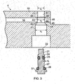
- Figure 4 shows the valve assembly 6, 7 with the valve stem 21 inserted in position within the valve chamber 11.
- the O-ring seal 25 has been compressed to diameter d 1 by passage through the transition region 48 and has had no, or negligible, contact with sharp edges 45 where the cross-bore 12 opens into the valve chamber 11.
- the increased diameter d 2 of the third portion 43 extends at least as far as the extremes of the opening or openings of the cross-bore 12 into the valve chamber 11, along the valve axis.
- the third portion of the valve chamber entirely encompasses the opening of the cross-bore chamber into the valve chamber.
- FIG. 1 shows the cross-bore chamber 12 as traversing the valve chamber 11, this may be for manufacturing convenience (e.g. so that the fluid path 8b or 8a can be drilled from an external surface of the head assembly, and plugged at the outside ends with seals 49, 50 ( figures 1 and 2 ).
- the cross-bore chamber 12 need not traverse the valve chamber - it may merely open into one side of the valve chamber 11, i.e. defining only a single gallery communicating with and extending laterally from the valve chamber 11.
- the described advantages of the increased diameter of the third portion 43 still apply.
- the cross-bore 12 is shown as orthogonal to the valve chamber 11, the cross-bore could more generally be oblique or transverse to the valve chamber, and benefits of the increased diameter of the third portion 43 can still be realised.
- valve assembly 6, 7 of figures 1 to 4 provides the distal seal 28 by way of an O-ring 28 mounted on the valve stem 21 which compresses against the radial sealing surface 14.
- the valve stem 21 carries a non-compressible, radially-extending sealing surface (e.g. bevelled surface 51) and a compressible sealing surface (such as an O-ring) can be provided within the valve chamber 11.
- the valve seat may comprise a resilient seal member and the distal seal member of the valve stem 21 may comprise a radially-extending surface which is configured to engage with the resilient seal.
- the fuel cartridge 1 provides a multi-valve arrangement for safe operation. Hydrogen gas can be released from the reservoir 3 by actuation of the valve stems 21 on both valve assemblies 6 and 7.
- valve stem 21 of valve assembly 6 When valve stem 21 of valve assembly 6 is actuated by pressing on the actuation end 22 against the bias of spring 30, the O-ring 28 is displaced downward away from the radial sealing surface 14 thereby allowing fluid to flow from the valve cavity 19a and into the cross-bore 12. Fluid flows to the second valve assembly 7 via the cross-bore 12 / flow path 8b to valve cavity 19b.
- Valve assembly 7 operates in a similar way by actuation of the valve stem 21 from the actuation end 22, allowing fluid to pass the distal seal and into cross-bore 15 / fluid path 8a, and from there to outlet 5.
- the valve assemblies 6, 7 have been described in relation to cross-sectional diameters of the first and third portions 41, 43 of the valve chamber 11.
- the cross-sectional diameter of the third portion 43 will be understood to refer to the diameter of the valve chamber as defined at positions other than the exact locations where the cross-bore 12 opens into the valve chamber 11, i.e. where the wall of the valve chamber is locally removed by the presence of the cross-bore.
- the opening of the cross-bore 12 into the valve chamber 11 will generally describe a somewhat elliptical aperture, i.e. a circular aperture that is curved out of the plane of the circle by intersection of the circular chamber of cross-bore 12 with a wall of chamber 11 that is itself curved.
- the third portion 43 of the valve chamber 11 provides a stepped bore for the valve chamber at the point of cross-drilling of the cross-bore 12 through the valve chamber, to provide a clearance fit for passage of the proximal valve seal 25 along the valve chamber 11 past the cross-bore.
- valve assembly has been described above specifically in the context of a fuel cartridge, the valve assembly described and claimed can be deployed in many other applications other than as a control valve in a fuel cartridge.
Landscapes
- Engineering & Computer Science (AREA)
- General Engineering & Computer Science (AREA)
- Mechanical Engineering (AREA)
- Physics & Mathematics (AREA)
- Fluid Mechanics (AREA)
- Lift Valve (AREA)
Claims (14)
- Cartouche de combustible à hydrogène (1) comprenant :une chambre à combustible (3) ;une sortie (5) ;un premier ensemble vanne (6) disposé entre la chambre à combustible et la sortie, le premier ensemble vanne comprenant :un deuxième ensemble vanne (7) comprenant une tige de vanne (21) pour actionnement, et disposé entre la chambre de vanne (3) et la sortie (5) ;une tige de vanne (21) ayant un élément d'étanchéité proximal résistant (25) disposé autour de la tige et un élément d'étanchéité distal (28) disposé autour de la tige, les éléments d'étanchéité proximal et distal étant séparés axialement l'un de l'autre le long de la tige de vanne ;un logement (10) délimitant une chambre de vanne (11) dans lequel la tige de vanne (21) est confinée de manière à pouvoir être déplacée axialement à l'intérieur de la chambre de vanne, le logement délimitant une première partie (41) de la chambre de vanne dans laquelle l'élément d'étanchéité proximal (25) se trouve et une deuxième partie (42) de la chambre de vanne dans laquelle l'élément d'étanchéité distal (28) se trouve, et délimitant en outre une chambre d'alésage transversal (12) qui s'ouvre dans la chambre de vanne dans une troisième partie (43) entre les première et deuxième parties ;dans lequel la troisième partie (43) présente un diamètre de section transversale minimum supérieur au diamètre de section transversale de la première partie ;
une chambre d'alésage transversal (12) s'étendant entre le premier ensemble vanne et le deuxième ensemble vanne, les ensembles vannes étant conçus ensemble pour permettre la libération de fluide depuis la chambre à combustible vers la sortie via les premier et deuxième ensembles vannes et la chambre d'alésage transversal lors de l'actionnement des tiges de vannes des premier et deuxième ensembles vannes. - Cartouche de combustible à hydrogène selon la revendication 1 dans laquelle la troisième partie (43) de la chambre de vanne (11) présente un diamètre minimum (d2) supérieur ou égal au diamètre non compressé de l'élément d'étanchéité proximal (25).
- Cartouche de combustible à hydrogène selon la revendication 1 dans laquelle la première partie (41) de la chambre de vanne (11) présente un diamètre (d1) inférieur à un diamètre non compressé de l'élément d'étanchéité proximal (25).
- Cartouche de combustible à hydrogène selon la revendication 1 dans laquelle la troisième partie (43) de la chambre de vanne (11) couvre entièrement l'ouverture de la chambre d'alésage transversal (12) dans la chambre de vanne (11).
- Cartouche de combustible à hydrogène selon la revendication 1 dans laquelle la deuxième partie (42) délimite un siège de vanne (14) de l'élément d'étanchéité distal (28).
- Cartouche de combustible à hydrogène selon la revendication 1 comprenant en outre un bord effilé (48) entre la première partie (41) de la chambre de vanne et la troisième partie (43) de la chambre de vanne (11).
- Cartouche de combustible à hydrogène selon la revendication 1 comprenant en outre une partie de transition (48) de la chambre de vanne (11) s'étendant entre la première partie (41) et la troisième partie (43), la partie de transition comprenant une partie de diamètre diminuant du diamètre (d2) de la troisième partie (43) au diamètre (d1) de la première partie (41).
- Cartouche de combustible à hydrogène selon la revendication 1 dans laquelle l'élément d'étanchéité proximal (25) comprend un joint torique autour de la tige de vanne (21).
- Cartouche de combustible à hydrogène selon la revendication 8 dans laquelle l'élément d'étanchéité proximal (25) comprend deux joints toriques (25a, 25b) disposés autour de la tige de vanne (21), les joints toriques étant séparés l'un de l'autre le long de la tige de vanne.
- Cartouche de combustible à hydrogène selon la revendication 7 dans laquelle la tige de vanne (21) présente un évidement circonférentiel (26) dans lequel un joint torique est confiné, le joint torique (25) présentant un diamètre extérieur non compressé inférieur ou égal au diamètre (d2) de la troisième partie (43) de la chambre de vanne (11) pendant l'installation de la tige de vanne dans la chambre de vanne, le joint torique étant compressé dans la première partie (41) de la chambre de vanne (11) par la partie de transition tandis que la tige de vanne se déplace vers la première partie de la chambre de vanne.
- Cartouche de combustible à hydrogène selon la revendication 5 dans laquelle le siège de vanne (14) comprend une section effilée de la deuxième partie (42) de la chambre de vanne (11).
- Cartouche de combustible à hydrogène selon la revendication 11 dans laquelle l'élément d'étanchéité distal (28) comprend un joint torique disposé autour de la tige de vanne (21) et conçu pour assurer l'étanchéité contre la partie effilée (14) de la chambre de vanne (11) lorsque la tige de vanne est sollicitée vers une position proximale.
- Cartouche de combustible à hydrogène selon la revendication 5 dans laquelle le siège de vanne (14) comprend un élément d'étanchéité résistant et l'élément d'étanchéité distal de la tige de vanne comprend une surface s'étendant radialement (51) conçue pour venir en prise avec le joint résistant.
- Cartouche de combustible à hydrogène selon la revendication 1 dans laquelle la chambre d'alésage transversal (12) traverse la chambre de vanne dans la troisième partie (43).
Applications Claiming Priority (2)
| Application Number | Priority Date | Filing Date | Title |
|---|---|---|---|
| GB1400210.9A GB2521868A (en) | 2014-01-07 | 2014-01-07 | Valve assembly |
| PCT/GB2015/050010 WO2015104536A1 (fr) | 2014-01-07 | 2015-01-06 | Ensemble vanne |
Publications (2)
| Publication Number | Publication Date |
|---|---|
| EP3094896A1 EP3094896A1 (fr) | 2016-11-23 |
| EP3094896B1 true EP3094896B1 (fr) | 2018-09-19 |
Family
ID=50190996
Family Applications (1)
| Application Number | Title | Priority Date | Filing Date |
|---|---|---|---|
| EP15702827.5A Not-in-force EP3094896B1 (fr) | 2014-01-07 | 2015-01-06 | Ensemble vanne |
Country Status (4)
| Country | Link |
|---|---|
| US (1) | US10145477B2 (fr) |
| EP (1) | EP3094896B1 (fr) |
| GB (1) | GB2521868A (fr) |
| WO (1) | WO2015104536A1 (fr) |
Families Citing this family (5)
| Publication number | Priority date | Publication date | Assignee | Title |
|---|---|---|---|---|
| US10612670B2 (en) * | 2015-10-23 | 2020-04-07 | Culligan International Company | Control valve for fluid treatment apparatus |
| US11242673B2 (en) * | 2017-01-18 | 2022-02-08 | Aquor Water Systems, Incorporated | Anti-freezing water valve with optional anti-siphon assembly and water-valve accessories |
| US11186970B2 (en) | 2017-03-29 | 2021-11-30 | Aquor Water Systems, Incorporated | Anti-freezing water valve configured for underground (buried) use and with optional anti-siphon assembly, and water-valve accessories |
| WO2018183758A1 (fr) | 2017-03-29 | 2018-10-04 | Aquor Water Systems, Incorporated | Tête d'extincteur d'incendie amovible comprenant une soupape d'admission d'eau |
| US12485216B2 (en) * | 2019-03-29 | 2025-12-02 | Carmo Holding Aps | Cross valve |
Family Cites Families (10)
| Publication number | Priority date | Publication date | Assignee | Title |
|---|---|---|---|---|
| US4316600A (en) * | 1980-06-04 | 1982-02-23 | Parise & Sons, Inc. | Fast acting, nonrepairable plastic on/off valve |
| CH662950A5 (de) | 1984-03-30 | 1987-11-13 | Johann Georg Mohler | Automatisch und von hand ausloesbares tragbares feuerloeschgeraet. |
| JP3762809B2 (ja) | 1996-05-01 | 2006-04-05 | 株式会社不二工機 | 電動弁 |
| US6244572B1 (en) * | 1998-10-05 | 2001-06-12 | Robert Delsole | Carburetor float bowl drain screw and recovery system |
| US6367499B2 (en) * | 2000-03-02 | 2002-04-09 | Hamai Industries Limited | Safety valve |
| DE10021997B4 (de) | 2000-05-05 | 2004-08-12 | Feuerschutz Emil Jockel | Dauerdruck-Handfeuerlöscher |
| IT1317563B1 (it) * | 2000-05-24 | 2003-07-09 | Flii Guerra & Figli S R L | Valvola a sfera bidirezionale utilizzabile particolarmente per gasfrigorigeni ecologici |
| DE10134972A1 (de) * | 2001-07-24 | 2003-02-20 | Demag Cranes & Components Gmbh | Durchlassventil für Strömungsmedium, insbesondere ein pneumatisches Drosselventil |
| EP2195566B1 (fr) * | 2007-08-23 | 2012-01-25 | Norgren Limited | Isolateur de clapet à bille |
| US7967039B2 (en) | 2007-12-06 | 2011-06-28 | Ausco Inc. | Seal assembly for a source of pressurized fluid |
-
2014
- 2014-01-07 GB GB1400210.9A patent/GB2521868A/en not_active Withdrawn
-
2015
- 2015-01-06 EP EP15702827.5A patent/EP3094896B1/fr not_active Not-in-force
- 2015-01-06 US US15/109,792 patent/US10145477B2/en not_active Expired - Fee Related
- 2015-01-06 WO PCT/GB2015/050010 patent/WO2015104536A1/fr not_active Ceased
Also Published As
| Publication number | Publication date |
|---|---|
| US10145477B2 (en) | 2018-12-04 |
| WO2015104536A1 (fr) | 2015-07-16 |
| EP3094896A1 (fr) | 2016-11-23 |
| GB201400210D0 (en) | 2014-02-26 |
| US20160327164A1 (en) | 2016-11-10 |
| GB2521868A (en) | 2015-07-08 |
Similar Documents
| Publication | Publication Date | Title |
|---|---|---|
| EP3094896B1 (fr) | Ensemble vanne | |
| US10584561B2 (en) | Dirty fluid pressure regulator and control valve | |
| US4121619A (en) | Tapered valves with conical seats | |
| BR112015015799B1 (pt) | Válvula de gaveta | |
| KR102342755B1 (ko) | 밸브 장치 | |
| EP3011129B1 (fr) | Dispositif pour assurer une circulation continue dans un forage de puits | |
| US8668015B2 (en) | Dual check valve | |
| JP7145884B2 (ja) | 残圧機能を有するコンパクトなガスボンベ弁 | |
| US20070193633A1 (en) | Self-contained check valve module | |
| US9617812B2 (en) | Drillstring valve | |
| US10133282B2 (en) | Shuttle valve with durable soft seal | |
| US12044327B2 (en) | Multi-function subplate mounted valve | |
| CN112412916B (zh) | 一种基于顺序减压溢流功能的液压复合阀 | |
| GB2443920A (en) | Relief gate valve | |
| US12222040B2 (en) | Sliding spool valves, and methods therefor | |
| CA2968380C (fr) | Ensembles soupapes d'extraction au gaz et procedes d'assemblage de ceux-ci | |
| US6792965B2 (en) | Shuttle valve assembly | |
| RU2455546C1 (ru) | Обратный клапан | |
| US20180073643A1 (en) | Improved shear seal assembly | |
| KR20210073576A (ko) | 보지밸브 부착 공기압 실린더 장치 | |
| CN219529431U (zh) | 一种溢流阀 | |
| JP4976175B2 (ja) | ガス供給接続具 | |
| CN121576449A (zh) | 一种闭式系统超调压力切断阀及使用方法 | |
| CN121897280A (zh) | 一种具有多重密封机构的裸眼多通道封隔器 |
Legal Events
| Date | Code | Title | Description |
|---|---|---|---|
| PUAI | Public reference made under article 153(3) epc to a published international application that has entered the european phase |
Free format text: ORIGINAL CODE: 0009012 |
|
| 17P | Request for examination filed |
Effective date: 20160802 |
|
| AK | Designated contracting states |
Kind code of ref document: A1 Designated state(s): AL AT BE BG CH CY CZ DE DK EE ES FI FR GB GR HR HU IE IS IT LI LT LU LV MC MK MT NL NO PL PT RO RS SE SI SK SM TR |
|
| AX | Request for extension of the european patent |
Extension state: BA ME |
|
| DAX | Request for extension of the european patent (deleted) | ||
| GRAP | Despatch of communication of intention to grant a patent |
Free format text: ORIGINAL CODE: EPIDOSNIGR1 |
|
| STAA | Information on the status of an ep patent application or granted ep patent |
Free format text: STATUS: GRANT OF PATENT IS INTENDED |
|
| INTG | Intention to grant announced |
Effective date: 20180403 |
|
| GRAS | Grant fee paid |
Free format text: ORIGINAL CODE: EPIDOSNIGR3 |
|
| GRAA | (expected) grant |
Free format text: ORIGINAL CODE: 0009210 |
|
| STAA | Information on the status of an ep patent application or granted ep patent |
Free format text: STATUS: THE PATENT HAS BEEN GRANTED |
|
| AK | Designated contracting states |
Kind code of ref document: B1 Designated state(s): AL AT BE BG CH CY CZ DE DK EE ES FI FR GB GR HR HU IE IS IT LI LT LU LV MC MK MT NL NO PL PT RO RS SE SI SK SM TR |
|
| REG | Reference to a national code |
Ref country code: GB Ref legal event code: FG4D |
|
| REG | Reference to a national code |
Ref country code: CH Ref legal event code: EP |
|
| REG | Reference to a national code |
Ref country code: DE Ref legal event code: R096 Ref document number: 602015016598 Country of ref document: DE |
|
| REG | Reference to a national code |
Ref country code: AT Ref legal event code: REF Ref document number: 1043622 Country of ref document: AT Kind code of ref document: T Effective date: 20181015 |
|
| REG | Reference to a national code |
Ref country code: IE Ref legal event code: FG4D |
|
| REG | Reference to a national code |
Ref country code: NL Ref legal event code: MP Effective date: 20180919 |
|
| PG25 | Lapsed in a contracting state [announced via postgrant information from national office to epo] |
Ref country code: SE Free format text: LAPSE BECAUSE OF FAILURE TO SUBMIT A TRANSLATION OF THE DESCRIPTION OR TO PAY THE FEE WITHIN THE PRESCRIBED TIME-LIMIT Effective date: 20180919 Ref country code: RS Free format text: LAPSE BECAUSE OF FAILURE TO SUBMIT A TRANSLATION OF THE DESCRIPTION OR TO PAY THE FEE WITHIN THE PRESCRIBED TIME-LIMIT Effective date: 20180919 Ref country code: NO Free format text: LAPSE BECAUSE OF FAILURE TO SUBMIT A TRANSLATION OF THE DESCRIPTION OR TO PAY THE FEE WITHIN THE PRESCRIBED TIME-LIMIT Effective date: 20181219 Ref country code: BG Free format text: LAPSE BECAUSE OF FAILURE TO SUBMIT A TRANSLATION OF THE DESCRIPTION OR TO PAY THE FEE WITHIN THE PRESCRIBED TIME-LIMIT Effective date: 20181219 Ref country code: LT Free format text: LAPSE BECAUSE OF FAILURE TO SUBMIT A TRANSLATION OF THE DESCRIPTION OR TO PAY THE FEE WITHIN THE PRESCRIBED TIME-LIMIT Effective date: 20180919 Ref country code: FI Free format text: LAPSE BECAUSE OF FAILURE TO SUBMIT A TRANSLATION OF THE DESCRIPTION OR TO PAY THE FEE WITHIN THE PRESCRIBED TIME-LIMIT Effective date: 20180919 Ref country code: GR Free format text: LAPSE BECAUSE OF FAILURE TO SUBMIT A TRANSLATION OF THE DESCRIPTION OR TO PAY THE FEE WITHIN THE PRESCRIBED TIME-LIMIT Effective date: 20181220 |
|
| REG | Reference to a national code |
Ref country code: LT Ref legal event code: MG4D |
|
| PG25 | Lapsed in a contracting state [announced via postgrant information from national office to epo] |
Ref country code: HR Free format text: LAPSE BECAUSE OF FAILURE TO SUBMIT A TRANSLATION OF THE DESCRIPTION OR TO PAY THE FEE WITHIN THE PRESCRIBED TIME-LIMIT Effective date: 20180919 Ref country code: LV Free format text: LAPSE BECAUSE OF FAILURE TO SUBMIT A TRANSLATION OF THE DESCRIPTION OR TO PAY THE FEE WITHIN THE PRESCRIBED TIME-LIMIT Effective date: 20180919 Ref country code: AL Free format text: LAPSE BECAUSE OF FAILURE TO SUBMIT A TRANSLATION OF THE DESCRIPTION OR TO PAY THE FEE WITHIN THE PRESCRIBED TIME-LIMIT Effective date: 20180919 |
|
| PGFP | Annual fee paid to national office [announced via postgrant information from national office to epo] |
Ref country code: FR Payment date: 20181218 Year of fee payment: 5 |
|
| REG | Reference to a national code |
Ref country code: AT Ref legal event code: MK05 Ref document number: 1043622 Country of ref document: AT Kind code of ref document: T Effective date: 20180919 |
|
| PG25 | Lapsed in a contracting state [announced via postgrant information from national office to epo] |
Ref country code: ES Free format text: LAPSE BECAUSE OF FAILURE TO SUBMIT A TRANSLATION OF THE DESCRIPTION OR TO PAY THE FEE WITHIN THE PRESCRIBED TIME-LIMIT Effective date: 20180919 Ref country code: NL Free format text: LAPSE BECAUSE OF FAILURE TO SUBMIT A TRANSLATION OF THE DESCRIPTION OR TO PAY THE FEE WITHIN THE PRESCRIBED TIME-LIMIT Effective date: 20180919 Ref country code: CZ Free format text: LAPSE BECAUSE OF FAILURE TO SUBMIT A TRANSLATION OF THE DESCRIPTION OR TO PAY THE FEE WITHIN THE PRESCRIBED TIME-LIMIT Effective date: 20180919 Ref country code: RO Free format text: LAPSE BECAUSE OF FAILURE TO SUBMIT A TRANSLATION OF THE DESCRIPTION OR TO PAY THE FEE WITHIN THE PRESCRIBED TIME-LIMIT Effective date: 20180919 Ref country code: AT Free format text: LAPSE BECAUSE OF FAILURE TO SUBMIT A TRANSLATION OF THE DESCRIPTION OR TO PAY THE FEE WITHIN THE PRESCRIBED TIME-LIMIT Effective date: 20180919 Ref country code: EE Free format text: LAPSE BECAUSE OF FAILURE TO SUBMIT A TRANSLATION OF THE DESCRIPTION OR TO PAY THE FEE WITHIN THE PRESCRIBED TIME-LIMIT Effective date: 20180919 Ref country code: IS Free format text: LAPSE BECAUSE OF FAILURE TO SUBMIT A TRANSLATION OF THE DESCRIPTION OR TO PAY THE FEE WITHIN THE PRESCRIBED TIME-LIMIT Effective date: 20190119 Ref country code: PL Free format text: LAPSE BECAUSE OF FAILURE TO SUBMIT A TRANSLATION OF THE DESCRIPTION OR TO PAY THE FEE WITHIN THE PRESCRIBED TIME-LIMIT Effective date: 20180919 Ref country code: IT Free format text: LAPSE BECAUSE OF FAILURE TO SUBMIT A TRANSLATION OF THE DESCRIPTION OR TO PAY THE FEE WITHIN THE PRESCRIBED TIME-LIMIT Effective date: 20180919 |
|
| PG25 | Lapsed in a contracting state [announced via postgrant information from national office to epo] |
Ref country code: PT Free format text: LAPSE BECAUSE OF FAILURE TO SUBMIT A TRANSLATION OF THE DESCRIPTION OR TO PAY THE FEE WITHIN THE PRESCRIBED TIME-LIMIT Effective date: 20190119 Ref country code: SM Free format text: LAPSE BECAUSE OF FAILURE TO SUBMIT A TRANSLATION OF THE DESCRIPTION OR TO PAY THE FEE WITHIN THE PRESCRIBED TIME-LIMIT Effective date: 20180919 Ref country code: SK Free format text: LAPSE BECAUSE OF FAILURE TO SUBMIT A TRANSLATION OF THE DESCRIPTION OR TO PAY THE FEE WITHIN THE PRESCRIBED TIME-LIMIT Effective date: 20180919 |
|
| REG | Reference to a national code |
Ref country code: DE Ref legal event code: R097 Ref document number: 602015016598 Country of ref document: DE |
|
| PLBE | No opposition filed within time limit |
Free format text: ORIGINAL CODE: 0009261 |
|
| STAA | Information on the status of an ep patent application or granted ep patent |
Free format text: STATUS: NO OPPOSITION FILED WITHIN TIME LIMIT |
|
| PG25 | Lapsed in a contracting state [announced via postgrant information from national office to epo] |
Ref country code: DK Free format text: LAPSE BECAUSE OF FAILURE TO SUBMIT A TRANSLATION OF THE DESCRIPTION OR TO PAY THE FEE WITHIN THE PRESCRIBED TIME-LIMIT Effective date: 20180919 |
|
| 26N | No opposition filed |
Effective date: 20190620 |
|
| PG25 | Lapsed in a contracting state [announced via postgrant information from national office to epo] |
Ref country code: MC Free format text: LAPSE BECAUSE OF FAILURE TO SUBMIT A TRANSLATION OF THE DESCRIPTION OR TO PAY THE FEE WITHIN THE PRESCRIBED TIME-LIMIT Effective date: 20180919 |
|
| REG | Reference to a national code |
Ref country code: CH Ref legal event code: PL |
|
| PG25 | Lapsed in a contracting state [announced via postgrant information from national office to epo] |
Ref country code: LU Free format text: LAPSE BECAUSE OF NON-PAYMENT OF DUE FEES Effective date: 20190106 |
|
| REG | Reference to a national code |
Ref country code: BE Ref legal event code: MM Effective date: 20190131 |
|
| REG | Reference to a national code |
Ref country code: IE Ref legal event code: MM4A |
|
| PG25 | Lapsed in a contracting state [announced via postgrant information from national office to epo] |
Ref country code: SI Free format text: LAPSE BECAUSE OF FAILURE TO SUBMIT A TRANSLATION OF THE DESCRIPTION OR TO PAY THE FEE WITHIN THE PRESCRIBED TIME-LIMIT Effective date: 20180919 |
|
| PG25 | Lapsed in a contracting state [announced via postgrant information from national office to epo] |
Ref country code: BE Free format text: LAPSE BECAUSE OF NON-PAYMENT OF DUE FEES Effective date: 20190131 |
|
| PG25 | Lapsed in a contracting state [announced via postgrant information from national office to epo] |
Ref country code: CH Free format text: LAPSE BECAUSE OF NON-PAYMENT OF DUE FEES Effective date: 20190131 Ref country code: LI Free format text: LAPSE BECAUSE OF NON-PAYMENT OF DUE FEES Effective date: 20190131 |
|
| PG25 | Lapsed in a contracting state [announced via postgrant information from national office to epo] |
Ref country code: IE Free format text: LAPSE BECAUSE OF NON-PAYMENT OF DUE FEES Effective date: 20190106 |
|
| PG25 | Lapsed in a contracting state [announced via postgrant information from national office to epo] |
Ref country code: TR Free format text: LAPSE BECAUSE OF FAILURE TO SUBMIT A TRANSLATION OF THE DESCRIPTION OR TO PAY THE FEE WITHIN THE PRESCRIBED TIME-LIMIT Effective date: 20180919 |
|
| PGFP | Annual fee paid to national office [announced via postgrant information from national office to epo] |
Ref country code: DE Payment date: 20200129 Year of fee payment: 6 Ref country code: GB Payment date: 20200127 Year of fee payment: 6 |
|
| PG25 | Lapsed in a contracting state [announced via postgrant information from national office to epo] |
Ref country code: MT Free format text: LAPSE BECAUSE OF NON-PAYMENT OF DUE FEES Effective date: 20190106 |
|
| PG25 | Lapsed in a contracting state [announced via postgrant information from national office to epo] |
Ref country code: CY Free format text: LAPSE BECAUSE OF FAILURE TO SUBMIT A TRANSLATION OF THE DESCRIPTION OR TO PAY THE FEE WITHIN THE PRESCRIBED TIME-LIMIT Effective date: 20180919 |
|
| PG25 | Lapsed in a contracting state [announced via postgrant information from national office to epo] |
Ref country code: FR Free format text: LAPSE BECAUSE OF NON-PAYMENT OF DUE FEES Effective date: 20200131 Ref country code: HU Free format text: LAPSE BECAUSE OF FAILURE TO SUBMIT A TRANSLATION OF THE DESCRIPTION OR TO PAY THE FEE WITHIN THE PRESCRIBED TIME-LIMIT; INVALID AB INITIO Effective date: 20150106 |
|
| REG | Reference to a national code |
Ref country code: DE Ref legal event code: R119 Ref document number: 602015016598 Country of ref document: DE |
|
| GBPC | Gb: european patent ceased through non-payment of renewal fee |
Effective date: 20210106 |
|
| PG25 | Lapsed in a contracting state [announced via postgrant information from national office to epo] |
Ref country code: GB Free format text: LAPSE BECAUSE OF NON-PAYMENT OF DUE FEES Effective date: 20210106 Ref country code: DE Free format text: LAPSE BECAUSE OF NON-PAYMENT OF DUE FEES Effective date: 20210803 |
|
| PG25 | Lapsed in a contracting state [announced via postgrant information from national office to epo] |
Ref country code: MK Free format text: LAPSE BECAUSE OF FAILURE TO SUBMIT A TRANSLATION OF THE DESCRIPTION OR TO PAY THE FEE WITHIN THE PRESCRIBED TIME-LIMIT Effective date: 20180919 |