EP3095499A1 - Dispositif de filtre - Google Patents
Dispositif de filtre Download PDFInfo
- Publication number
- EP3095499A1 EP3095499A1 EP16167079.9A EP16167079A EP3095499A1 EP 3095499 A1 EP3095499 A1 EP 3095499A1 EP 16167079 A EP16167079 A EP 16167079A EP 3095499 A1 EP3095499 A1 EP 3095499A1
- Authority
- EP
- European Patent Office
- Prior art keywords
- filter
- pressure
- pressure vessel
- filter plate
- filter device
- Prior art date
- Legal status (The legal status is an assumption and is not a legal conclusion. Google has not performed a legal analysis and makes no representation as to the accuracy of the status listed.)
- Withdrawn
Links
Images


Classifications
-
- B—PERFORMING OPERATIONS; TRANSPORTING
- B01—PHYSICAL OR CHEMICAL PROCESSES OR APPARATUS IN GENERAL
- B01D—SEPARATION
- B01D33/00—Filters with filtering elements which move during the filtering operation
- B01D33/15—Filters with filtering elements which move during the filtering operation with rotary plane filtering surfaces
- B01D33/17—Filters with filtering elements which move during the filtering operation with rotary plane filtering surfaces with rotary filtering tables
-
- B—PERFORMING OPERATIONS; TRANSPORTING
- B01—PHYSICAL OR CHEMICAL PROCESSES OR APPARATUS IN GENERAL
- B01D—SEPARATION
- B01D33/00—Filters with filtering elements which move during the filtering operation
- B01D33/58—Handling the filter cake in the filter for purposes other than for regenerating the filter cake remaining on the filtering element
- B01D33/60—Handling the filter cake in the filter for purposes other than for regenerating the filter cake remaining on the filtering element for washing
-
- B—PERFORMING OPERATIONS; TRANSPORTING
- B01—PHYSICAL OR CHEMICAL PROCESSES OR APPARATUS IN GENERAL
- B01D—SEPARATION
- B01D33/00—Filters with filtering elements which move during the filtering operation
- B01D33/58—Handling the filter cake in the filter for purposes other than for regenerating the filter cake remaining on the filtering element
- B01D33/62—Handling the filter cake in the filter for purposes other than for regenerating the filter cake remaining on the filtering element for drying
- B01D33/66—Handling the filter cake in the filter for purposes other than for regenerating the filter cake remaining on the filtering element for drying by gases or by heating
- B01D33/663—Handling the filter cake in the filter for purposes other than for regenerating the filter cake remaining on the filtering element for drying by gases or by heating by direct contact with a fluid
-
- B—PERFORMING OPERATIONS; TRANSPORTING
- B01—PHYSICAL OR CHEMICAL PROCESSES OR APPARATUS IN GENERAL
- B01D—SEPARATION
- B01D33/00—Filters with filtering elements which move during the filtering operation
- B01D33/80—Accessories
- B01D33/82—Means for pressure distribution
Definitions
- the invention relates to a filter device for separating solids from a suspension containing the solids and a suspension liquid.
- plate filters which rotate in operation about a vertical axis, so that they can fully exploit gravity.
- the cake formation and the filtration can be supported by a negative pressure applied on the back.
- pressure rotary filters In comparison with pressure rotary filters, however, the limited by the physics limitation of useful for cake formation and filtration pressure difference is disadvantageous.
- disk filters In contrast to disk filters, disk filters are arranged rotating about a horizontal axis and only partially submerge in the suspension to be filtered. They also use hydrostatic and hydrodynamic effects for cake formation and filtration. Similar to the pressure rotary filters can cake formation and Filtration also with this type of filter can not be fully supported by gravity.
- a filter device comprising a pressure vessel with a supply for pressure medium, by means of which the interior of the pressure vessel can be brought to an increased compared to the ambient pressure outside the pressure vessel pressure, at least one recorded in the pressure vessel to a substantially vertical extending rotational axis rotatably mounted filter plate, which has a plurality of filter cells, each filter cell is associated with a filter medium whose one side, the high pressure side, facing the interior of the pressure vessel, while the side facing away from the interior of the pressure vessel side, the low pressure side, with a connected to the filter plate
- Ab2020 effete is connected, in turn, via a rotary joint assembly downstream of a stationary Ab2020 Gustavssystem, a stationary Zu200 Gustavssystem for supplying suspension to be filtered and for supplying at least one treatment medium for treating the filter cake formed by the solids in the filter cells on the filter medium, and a pressure lock for discharging the solids.
- the filter device combines the advantages of pressure rotary filters and plate filters, without at the same time having their disadvantages. Due to the use of at least one filter plate on the surface of the filter cake is formed, the gravity at all points of the filter medium can be fully used for cake formation or filtration. In addition, the high pressure side of the filter medium is the interior facing the pressure vessel, so that the suspension liquid or the treatment medium is pressed with an overpressure lying above the atmospheric pressure through the filter medium. The addition of gravity and compressive force improves filtration efficiency compared to the known types of filters.
- the filter medium can be made for example of metal, plastic, textile or composite material.
- a metal filter medium may be welded to the filter cell, while a filter medium of plastic, textile or composite will advantageously be clamped to the filter cell, e.g. by means of a fastening cord, a mounting plate or the like.
- the pressure vessel may comprise a pot-shaped lower container part and a lid-like upper reservoir part.
- the pressure vessel comprises at least two pressure chambers, namely a pressure chamber arranged above the filter plate and a pressure chamber arranged below the filter plate, which are preferably in pressure equalization connection with each other, so that the pressure prevailing in the pressure vessel does not affect the filter plate only from its top side applied where it is used for filtration, but also from the bottom.
- the filter plate can be arranged pressure-balanced in the pressure vessel, which on the one hand the formation of the filter plate with a stiffening in view of the pressure forces acting on its upper side stiffening construction and on the other hand, the provision of sealing means that it at its outer edge to the pressure vessel seal off, make unnecessary.
- the lid-like upper container part is designed so that it is free of functional elements of the filter device, it can be removed, for example, for maintenance work, without a great disassembly effort from the pot-like lower container part.
- This division of the pressure vessel is also during the factory installation of the filter device of great advantage, in particular in terms of time and cost savings.
- the upper edge of the pot-like lower container part can be arranged above the filter plate in order to facilitate the supply of the feed lines for suspension to be filtered and / or treatment medium to the top of the filter plate.
- the pressure in the pressure vessel may be, for example, about 6 bar.
- the filter device has a plurality of working zones which follow one another in the circumferential direction.
- a first working zone can be designed as an application work zone.
- the suspension to be filtered fed via a first supply line of the stationary supply line system can be applied to the filter medium of the filter cell (s) currently in the application work zone.
- the pressure medium for example a gas, such as air, pushes the suspension liquid through the filter medium, so that the solids remain as filter cake on the filter medium.
- At least one treatment working zone can be provided, which can be supplied via a further supply line of the stationary feed line system at least one treatment medium for treating the solids.
- the treatment work zone or at least one of the treatment work zones can be designed as a wash zone in which applied via a feed line of the stationary feed line system washing liquid applied to the filter cake and is forced through the pressure medium through the filter cake.
- at least one of the treatment work zones may be formed as a dehumidification zone, in which the filter cake at least a portion of the existing moisture in it is withdrawn. Usually, the dehumidification takes place by displacing the moisture present in the pores of the filter cake by means of a dehumidifying medium.
- the pressure medium As a dehumidifying medium can be used, for example, the pressure medium.
- the filter cake using superheated steam, in which case not only the displacement dehumidification but also a thermal dehumidification by evaporation of the moisture present in the pores of the filter cake can play a role.
- dehumidifying in connection with the present invention does not necessarily mean the complete removal of moisture. This is also true, although the dehumidifying zone is often called “drying zone” in the general language of the art. It is essential that the filter cake in the dehumidifying zone is not left to itself, whereby it can come to a certain loss of moisture by evaporation, but that is actively acted upon for dehumidification on the filter cake.
- a discharge working zone can be provided, in which the optionally washed and / or dehumidified solids are discharged from the filter device.
- a filter medium preparation working zone may also be provided, in which the filter medium is prepared for the next filtration cycle.
- the residual layer of solids which is still on the filter medium after the discharge for example, irradiated with water and / or exposed from the back of the filter medium forth a pressure surge and thereby broken.
- clogging of the filter medium can be prevented.
- each feed line of the stationary feed line system is assigned at least one discharge line of the stationary discharge line system.
- the filter plate may have an upwardly projecting edge on its outer circumference and / or on its inner circumference. Such an edge facilitates cake formation because it prevents the suspension from flowing away, thus ensuring that the solids settle on the filter media as the slurry liquid passes through the filter media.
- the edge could also be formed on the pressure vessel or formed by the pressure vessel.
- a peripheral edge of the filter plate avoids sealing problems.
- each filter cell is assigned a separate discharge line of the circulating discharge line system, this has the advantage that the filtrates of the individual filter cells can be discharged separately from one another. Due to the interaction of the discharge lines of the circulating Ab classroom Anlagenssystems and the stationary Ab2020 Anlagenssystems via the rotary joint assembly thus supplied in a particular work zone media can also be removed via the this working zone associated discharge line of the stationary Ab2020 effetssystems.
- the working-zone-wise supply and removal of the treatment media can be further assisted by the number of filter cells being greater than the number of working zones.
- the separation of the work zones from each other can be improved. In other words, this can reduce the fraction of the medium supplied in a certain working zone, which is not dissipated via the discharge line of the stationary discharge line system assigned to this working zone.
- the filter cells are designed in such a way that the medium supplied to a filter cell in a working zone is completely immersed in this Working zone associated discharge line of the stationary Abmonirieltungssystems has been removed before the corresponding filter cell leaves the working zone or the filter cell associated discharge line of the circulating AbDOM effetes is no longer fluidly connected to the work zone associated discharge line of the stationary Abdies effetssystems.
- the working zone-wise feeding and discharging of the treatment media it is for example possible to provide a plurality of washing zones, and perform in these a multi-stage countercurrent washing of the solids.
- the circumferential angle over which each of the filter cell-associated discharge lines of the recirculating purge line system in the rotary joint assembly is smaller than the circumferential angular distance the two circumferentially successive discharge lines of the stationary one Abvant effetssystems in the rotary joint assembly from each other.
- the filter cells can be separated from each other formed elements. This allows improved ease of maintenance, since in case of need not the entire filter plate needs to be replaced, but individual filter cells can be replaced.
- the filter plate is supported at its radially outer edge on the pressure vessel.
- the diameter of a filter plate of the Filter device according to the invention may for example be between about 3.0 m and about 3.5 m.
- a support of the filter plate or the filter cells only at the radially inner edge or by using additional elements, such as diagonal supports, is basically conceivable.
- an additional support of the filter plate or the filter cells on the radially outer edge simplify the structural design of the support.
- At least one of the supply lines for supplying suspension to be filtered and / or treatment medium can be connected to an overflow unit with an overflow edge or a trickle or nozzle unit with outlet openings.
- the overflow edge or the size and the distribution of the outlet openings can be designed such that over the entire radius of the filter plate per unit time and unit area of the filter plate, the same amount of suspension or treatment medium is delivered.
- the length of a radially inner circular arc section which passes through a feed unit during a predetermined time unit is shorter than the length of a circular arc section of equal width located radially outwardly, which passes through the feed unit during the same predetermined time unit.
- the discharge amount per radial length portion and time unit in the radial direction of the filter plate must increase to the outside. This can be achieved, for example, via a recessed overflow edge, wherein the recess surfaces thereof vary over the length of the overflow unit, ie in the radial direction.
- the discharge amount can be controlled by the number or / and the diameter of the outlet openings.
- the supply line is connected adjacent to the overflow unit or the trickle or nozzle unit whose respective quantity center.
- the "volume center" of the overflow unit is understood to mean that radial position of the overflow unit, radially within which as much suspension or treatment medium is discharged onto the filter plate as radially outside. With suitable positioning of the connection of the supply line can be dispensed with elaborate distribution devices between the supply and the overflow unit or the trickle or nozzle unit.
- the sealing arrangement may, for example, comprise at least one sealing lip which is in contact with the surface of the filter cake and which, for example, rests on it, which at least hampers, if not completely prevents, a return flow of suspension liquid or treatment medium into an adjacent working zone.
- a steam hood is arranged in the pressure vessel.
- the steam in the interior of the steam hood can be present at a pressure which is substantially equal to the pressure in the remaining pressure vessel.
- the vapor remains on the one hand in the steam hood and can not be reflected on cool surface portions of the pressure vessel.
- no cool gas can penetrate from the remaining pressure vessel into the steam hood and lead there to a cooling of the steam. by virtue of of the increased pressure in the steam hood, the steam is forced through the filter cake and dehumidifies it.
- the filter cell rotates about an axis deviating from the longitudinal axis and / or is foldable in itself.
- a discharge working zone of the filter device is associated with a screw conveyor with at least one discharge screw.
- the radially outer end of the discharge screw may be disposed radially inward of the edge thereof. The discharge screw then throws the solids only over the edge from where they pass through the post-pumped solids displaced and thus can be further promoted.
- the discharge screw comprises a disposed within the outer edge of the filter plate length portion and a disposed outside the outer edge of the filter plate length portion which are connected to each other via a common, extending above the edge drive shaft. In this way, the solids thrown over the edge by the inner length section can be conveyed from the outer longitudinal section further to the discharge opening.
- the discharge screw has a conical envelope surface whose lower peripheral portion is substantially parallel to the surface of the filter plate.
- envelope surface of the discharge screw is understood to mean that surface which is formed by the outer boundary line of the conveyor screw during its rotation.
- the discharge screw may be advantageous to increase the Austrags binelles when the direction of rotation of the drive shaft of the discharge screw is selected such that the respective closest to the filter plate portion of the envelope surface of the discharge screw moves against the direction of movement of the filter plate.
- the discharge screw is associated with a lifting device which temporarily lifts it as the edge advances between two successive filter cells.
- the discharge screw is partially enveloped, in particular such that only the contact area between the discharge screw and solid layer is not enveloped.
- the discharge screw can either be mounted on one side, i. be supported only on the housing of the pressure vessel or in the vicinity of the pressure vessel housing and project freely into the pressure vessel, or be stored on both sides, i. in addition also have a storage in the interior of the pressure vessel, for example, at least one extending transversely through the pressure vessel strut or at one of the lid-like upper container part of the pressure vessel outgoing carrier.
- a motor for example an electric motor, may be provided outside the pressure vessel, which may be connected directly or via a transmission to the drive shaft of the discharge screw.
- the solids discharged from the discharge screw can be conveyed, preferably under gravity, to a section provided with the pressure lock, at which the solids can be discharged from the filter device.
- the pressure lock may comprise, for example, a rotary valve or a flap lock.
- the pressure lock can be provided at the portion where the solids are removed from the filter device to reduce the pressure loss due to the solids from the Filter device escaping gas is formed.
- the rotary valve promotes solids continuously or clocked, the flap lock only clocked.
- An inlet end and an outlet end of the pressure lock are separated from each other pressure-tight. In this way, the amount of gas exiting the pressure vessel can be reduced, which in turn has the consequence that the pressure vessel to maintain a substantially constant pressure correspondingly less gas must be supplied.
- the discharge lines of the circulating discharge line system could be guided radially outward by the filter cells. According to the invention, however, it is proposed that the discharge lines of the circulating Abdies effets are guided radially inward and extend through the interior of a fixedly connected to the filter plate, the axis of rotation substantially concentric rotor shaft, as this allows a spatially compact design of the rotary joint assembly, which has a seal arrangement between the circulating evacuation conduit system and the stationary evacuation conduit system.
- the rotary joint assembly which is also called “control head”
- control head can with a rotation axis orthogonal to the contact surface, as a so-called plan control head, or with a circumferential direction be running around the axis of rotation contact surface, designed as a so-called neck control head.
- the discharge lines of the circulating Abdies can be performed.
- the outflow of the filtrate can take place with gravity support.
- the filtrate after passing through the filter medium, can flow directly to the rotor shaft. But it can also be provided below the filter medium, a gutter and / or a collection point, via which or the filtrate can reach the filter cell associated discharge line of the circulating AbDOM effetussystems.
- At least two rotor shaft bearings can be provided.
- the rotor shaft may extend from the underside of the pressure vessel into the pressure vessel, through the filter plate, and further up to the upper vessel portion of the pressure vessel housing.
- the rotor shaft may in this case on the one hand at the point where it passes through the housing of the pressure vessel, and on the other hand at the location of the inside of the lid-like upper pressure vessel part, to which it extends, be stored.
- the rotor shaft on the one hand as in the first embodiment, be stored at the point where it passes through the housing of the pressure vessel, and on the other hand in a region adjacent to the underside of the filter plate.
- the filter plate adjacent Storage may be supported, for example, via at least one transverse web which extends through the pressure vessel.
- the rotor shaft may be supported at two locations adjacent to the filter plate above and below the filter plate. Similar to the known from the second embodiment of the filter plate adjacent storage, and the two bearings of the third embodiment may each be supported on at least one transverse web.
- a fourth embodiment of the rotor shaft bearing combination combines the above the filter plate arranged storage of the third embodiment with the known from the first and second embodiments storage at the housing passage point of the rotor shaft.
- the rotor shaft is on the one hand, as known from the first, second and fourth embodiments, mounted on the housing passage and on the other hand in a region adjacent to the top of the filter plate, wherein the rotor shaft bearing, which is arranged above the filter plate, not, as known from the third and fourth embodiments, is supported via a crosspiece, but, as known from the first embodiment, via a device which is connected to the upper container part of the pressure vessel housing.
- a sixth embodiment of the rotor bearing is substantially analogous to the second embodiment, with the difference that the bearing arranged adjacent to the underside of the filter plate does not support the rotor shaft itself, but there a corresponding attached to the filter plate portion of the rotor shaft operatively connected to the filter plate stored is.
- the second and the sixth embodiment are advantageous because both the upper container part of the Pressure housing easily disassembled and a possible impairment of the above the filter plate arranged functional elements can be avoided.
- the passage of the rotor shaft through the housing for example by means of a stuffing box, a shaft seal, a PS seal ® or a mechanical seal, be sealed.
- the rotor shaft is connected to the end of the rotor shaft opposite the filter plate with a drive unit, for example an electric motor or a hydraulic drive.
- a drive unit for example an electric motor or a hydraulic drive.
- the drive unit either directly or via an intermediate unit, such as a gear transmission, a belt drive or chain drive, be connected to the rotor shaft.
- the drive unit can also be arranged above or even inside the pressure vessel.
- the filter device according to the invention can operate completely continuously. In principle, however, it is also conceivable to operate them clocked continuously, ie to continue rotating them by a predetermined number of filter cells, for example a filter cell, in a given time cycle. Even with the clocked continuous mode of operation, a quantity of suspension introduced into a filter cell of the filter plate passes successively through the various working zones, while further quantities of suspension are supplied to other filter cells of the filter plate.
- the pulsed continuous mode of operation thus differs from the batch mode in which a predetermined amount of suspension is always subjected to all treatment steps before fresh suspension is supplied again.
- the filter device according to the invention can be operated with a plurality of filter plates arranged one above the other.
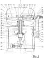
- FIG. 1 is an embodiment of the filter device according to the invention generally designated 10.
- the filter device 10 comprises a pressure housing 12, which is subdivided into a cover-like upper component 14 (hereinafter also referred to as “container cover 14") and a cup-shaped lower container part 16 (hereinafter also referred to as “container lower part 16").
- a filter medium 20 is arranged and which has an inner edge 22 and an outer edge 24.
- the outer edge 24 is the outer edge 24 on a projection 26 of the container base 16 of the pressure housing 12 supported.
- the filter plate 18 is operatively connected to a rotor shaft 28, which extends from the filter plate 18, starting in a substantially vertical direction through the container base 16 of the pressure housing 12 down through.
- a stuffing box 30 which also includes a lower bearing 32 and an upper bearing 34 for the rotor shaft 28 for rotatably supporting the rotor shaft 28.
- each filter cell 19 and its associated filter medium 20 a gap 36 is formed, which drops to a connection point 38 out.
- the intermediate space 36 is connected to a discharge line 39 of a discharge line system 40 formed by a plurality of similar discharge lines.
- each filter cell 19 is associated with a discharge line 39 of the circulating AbDOM Kochssystems 40.
- the discharge conduits 39 of the circulating discharge line system 40 which preferably have substantially identical dimensions, lead into and through the interior of the rotor shaft 28 to a rotary connection assembly 42 located outside the pressure vessel 12.
- a stationary Abgar Gustavssystems 44 arranged at the rotary union assembly 42 .
- the discharge lines 43 of the stationary Abgar Gustavssystems 44 are arranged distributed in the circumferential direction U about the rotation axis A and lead radially away from the rotary joint assembly 42. That the rotary joint assembly 42 is formed as a "shark control head".
- the rotor shaft 28 and with this the filter plate 18 is driven via an outside of the pressure vessel 12 arranged electric motor 46, which is connected in the illustrated embodiment with the rotor shaft 28 via a gear transmission 48.
- the rotor shaft 28, the rotary connection assembly 42, the electric motor 46 and the transmission 48 are supported via a support device 50, which in turn is attached to a frame 52 of the filter device 10.
- the pressure vessel 12 is supported directly and / or via intermediate elements on the frame 52.
- the filter device 10 further comprises various feed lines 84, 86, 88, 90, 92, 94 and 96 leading through the periphery of the lower container part 16 of the pressure vessel 12 into the pressure vessel 12, which will be described below with reference to FIG FIG. 2 will be described in detail, which is a top view of the filter device 10 in the direction of the arrow II in FIG. 1 with removed housing cover 14 shows.
- the region of the filter device 10 located above the filter plate 18 or the filter cells 19 can essentially be subdivided into eight work zones Z 1 to Z 8 , wherein each of the work zones is one of the feed lines 84, 86, 88, 90, 92, 94, 96 resp .,
- the discharge screw 56 is assigned.
- the stationary supply line 84 to be filtered suspension is applied to the filter medium 20 of the filter cells 19.
- the application of suspension to the filter medium 20 is likewise carried out continuously or clocked accordingly.
- the application of suspension to the filter medium 20 of the filter cell 19 is designed such that despite the substantially circular sector-shaped design of the filter cells 19 per unit time to each unit area of the present in this working zone filter cell (s) 19, the same amount of suspension is applied.
- the suspension liquid of the applied suspension is pressed by the pressure prevailing in the interior of the pressure vessel 12 through the filter medium 20, so that the solids contained in the suspension precipitate as filter cake on the filter medium 20, while the suspension liquid be derived by the circulating Abdiestechnischungssystem 40 and the stationary Abdiestechnischssystem 44.
- a treatment medium for example a washing liquid
- a treatment medium for example a washing liquid
- the feed lines 88, 90, 92 are also each used to supply treatment medium, in particular washing liquid for a second, third and fourth washing of the filter cake.
- the treatment media supplied by the stationary supply lines 86, 88, 90, 92 may be identical and / or different from each other.
- it is possible to carry out a countercurrent washing in the four working zones Z 2 to Z 5 in which the fifth working zone Z 5 is supplied with clean scrubbing liquid via the supply line 92 in order to make the filter cake already pre-scrubbed three times in the work zones Z 2 to Z 4 one last Time to wash with clean washing liquid.
- the washing liquid discharged from the fifth working zone Z 5 is then introduced via the supply line 90 into the fourth working zone Z 4 , etc., until finally the washing liquid discharged from the second working zone Z 2 or first washing zone is completely discharged from the filter device 10.
- the sixth working zone Z 6 is used for dehumidifying the filter cake. Therefore, this working zone is supplied via the stationary supply line 94, a dehumidifying medium.
- a gas is used as a dehumidifying medium and this used simultaneously as a pressurized gas. Thus, no separate compressed gas supply line needs to be provided.
- superheated steam can be used as a dehumidifying medium.
- a steam hood (not shown) open towards the filter cake into which the superheated steam is introduced.
- the pressure prevailing in the steam hood is advantageously set to a somewhat lower value than the pressure in the pressure container 12.
- the dehumidifying working zone Z 6 is followed by a discharge working zone Z 7 in which the filter cake is transported away from the filter plate 18 radially outwards by means of a discharge screw 56 to be described in detail below.
- any remaining solid residues are broken up on the filter medium 20 so that they no longer clog the filter medium 20.
- a treatment medium such as for example water
- a pressure recoil can be exerted on the filter cake from the rear side of the filter medium 20 in order to detach the filter cake from the filter medium 20.
- working zones Z 1 to Z 8 can be separated from each other by sealing arrangements (not shown), whereby it can be avoided or at least reduced that the treatment media of one working zone mix with those of another working zone.
- a discharge screw 56 is provided in the discharge zone Z 7 , which for removing the remaining after filtration on the filter medium 20 solids from the filter device 10th serves.
- the discharge screw 56 is subdivided into a longitudinal section 58 arranged within the outer edge 24 and a longitudinal section 60 arranged outside the outer edge 24. Both length sections 58 and 60 are driven via the same drive shaft 62, which in turn is driven directly or via a transmission by an electric motor 64.
- the solids resting on the filter medium 20 are conveyed radially outward from the longitudinal section 58 of the discharge screw 56 on the filter plate 18 and there via the outer edge 24 of the filter plate 18.
- the outer longitudinal section 60 of the discharge screw 56 transports the solids from there to a discharge chute 66, in which they fall down to a rotary valve 68.
- the rotary valve 68 comprises a cellular wheel 70, which has a plurality of cells 72.
- the cells 72 of the cellular wheel 70 are filled with the solids falling from above.
- the cellular wheel 70 rotates in a continuous or clocked manner about a substantially horizontal axis B.
- the cellular wheel 70 of the rotary valve 68 is driven by an electric motor 76 either directly or via a transmission.
- the electric motor 76, the rotary valve 68 and the discharge shaft 66 are connected via a holding device 78 to the frame 52.
- the discharge screw 56 is on the one hand at its point of passage through the pressure vessel 12 and on the other held on a transverse to the container base 16 of the pressure vessel 12 extending strut 80 by means of a (not shown) holder.
- the discharge screw 56 is further surrounded by a housing 82, which on the one hand prevents solids from being ejected from the discharge screw 56 and, on the other hand, provides storage for the drive shaft 62 of the discharge screw 56 at the two axial ends of the housing 82. Outside the pressure vessel 12, the housing 82 also serves to seal the pressure and hold the electric motor 64.
- FIG. 3 shows a sectional view through the rotary joint assembly 42 along the line III-III of FIG. 1 ,
- the discharge lines 39 of the circulating discharge line system 40 which extend horizontally within the rotor shaft 28 in this region, can be seen, which are open toward the outside of the rotor shaft 28.
- discharge lines 98, 102, 106, 110, 114, 118 of the stationary discharge line system 44 can be seen.
- one of the discharge lines 98, 102, 106, 110, 114, 118 of the stationary discharge line system 44 is associated with a receiving area 100, 104, 108, 112, 116, 120, which are separated from one another by sealing elements 122.
- the width of each sealing element 122 is greater than the maximum width of an opening of a discharge line of the circulating Ab classroomtechnischssystems 40 to the outside of the rotor shaft 28 out.
- the treatment medium supplied to a filter cell is fed after filtration to the filter cell 19 associated discharge line 39 of the circulating AbDOM effetes 40. Subsequently, the filtrate enters the Receiving area, with which the corresponding discharge line 39 of the circulating AbDOM effetes 40 is currently in communication, from where it is transported over the this receiving area associated discharge line of the stationary Ab gleich effetssystems 44 from the filter device 10.
- the discharge lines 98, 102, 106, 110, 114, 118 or the receiving areas 100, 104, 108, 112, 116, 120 of the discharge lines of the stationary discharge line system 44 are designed such that the respective width, i. the circumferential angle of a receiving area with the width, i. the circumferential angle, a working zone associated with the receiving area. Accordingly, in the case of a rotating filter plate 18, a discharge line 39 of the circulating discharge line system 40 communicates with a receiving region assigned to a working zone, such as the filter cell, which is associated with this discharge line 39 of the circulating discharge line system 40, is in communication with this working zone. As a result, the treatment medium supplied in the respective working zone can be removed separately from the filter device 10 after the filtration.
- the dehumidifying medium discharged from the dehumidifying working zone in the receiving region 120 is removed from the filter device 10.
- the filter plate 18 is provided with a plurality of oblique supports 54 for its stabilization. These need in the illustrated embodiment, but only the weight of the filter plate 18 together with the resting thereon filter cake and the respective treatment media to wear.
- the inner space 12a of the pressure vessel has a region 12a1 arranged above the filter plate 18 and a region 12a2 arranged below the filter plate 18 which communicate with one another via the gap between the pressure vessel 12 and the outer edge of the filter plate 18 are in pressure equalization connection.
- the same pressure prevails in both regions 12a1 and 12a2, so that the upper side and the lower side of the filter plate 18 are subjected to the same pressure and thus exert net pressure force on the filter plate 18.
Landscapes
- Chemical & Material Sciences (AREA)
- Chemical Kinetics & Catalysis (AREA)
- Filtration Of Liquid (AREA)
Applications Claiming Priority (1)
| Application Number | Priority Date | Filing Date | Title |
|---|---|---|---|
| DE102015209094.9A DE102015209094A1 (de) | 2015-05-19 | 2015-05-19 | Filtervorrichtung |
Publications (1)
| Publication Number | Publication Date |
|---|---|
| EP3095499A1 true EP3095499A1 (fr) | 2016-11-23 |
Family
ID=55854640
Family Applications (1)
| Application Number | Title | Priority Date | Filing Date |
|---|---|---|---|
| EP16167079.9A Withdrawn EP3095499A1 (fr) | 2015-05-19 | 2016-04-26 | Dispositif de filtre |
Country Status (2)
| Country | Link |
|---|---|
| EP (1) | EP3095499A1 (fr) |
| DE (1) | DE102015209094A1 (fr) |
Cited By (1)
| Publication number | Priority date | Publication date | Assignee | Title |
|---|---|---|---|---|
| CN120242590A (zh) * | 2025-06-09 | 2025-07-04 | 昆明然涛金属材料有限公司 | 一种分离纯化设备以及用于水解制氢的纯化方法 |
Citations (3)
| Publication number | Priority date | Publication date | Assignee | Title |
|---|---|---|---|---|
| FR1034697A (fr) * | 1950-12-19 | 1953-07-29 | Oliver United Filters | Vanne automatique perfectionnée |
| BE695472A (fr) * | 1967-03-14 | 1967-08-14 | ||
| WO2007096910A1 (fr) * | 2006-02-22 | 2007-08-30 | Comber S.R.L. | Secheur et filtre / secheur |
Family Cites Families (3)
| Publication number | Priority date | Publication date | Assignee | Title |
|---|---|---|---|---|
| DE1102105B (de) * | 1958-11-28 | 1961-03-16 | Dorr Oliver Inc | Drehbares Tischfilter |
| DE2015089A1 (en) * | 1970-03-28 | 1971-10-21 | Maschinenfabrik Buckau R. WoIfAG, 4048 Grevenbroich | Pressure-tight planar cell rotary filter |
| EP2926879B1 (fr) * | 2014-04-03 | 2017-09-27 | BOKELA Ingenieurgesellschaft für Mechanische Verfahrenstechnik mbH | Dispositif de filtre et procédé de filtration |
-
2015
- 2015-05-19 DE DE102015209094.9A patent/DE102015209094A1/de not_active Withdrawn
-
2016
- 2016-04-26 EP EP16167079.9A patent/EP3095499A1/fr not_active Withdrawn
Patent Citations (3)
| Publication number | Priority date | Publication date | Assignee | Title |
|---|---|---|---|---|
| FR1034697A (fr) * | 1950-12-19 | 1953-07-29 | Oliver United Filters | Vanne automatique perfectionnée |
| BE695472A (fr) * | 1967-03-14 | 1967-08-14 | ||
| WO2007096910A1 (fr) * | 2006-02-22 | 2007-08-30 | Comber S.R.L. | Secheur et filtre / secheur |
Cited By (1)
| Publication number | Priority date | Publication date | Assignee | Title |
|---|---|---|---|---|
| CN120242590A (zh) * | 2025-06-09 | 2025-07-04 | 昆明然涛金属材料有限公司 | 一种分离纯化设备以及用于水解制氢的纯化方法 |
Also Published As
| Publication number | Publication date |
|---|---|
| DE102015209094A1 (de) | 2016-11-24 |
Similar Documents
| Publication | Publication Date | Title |
|---|---|---|
| EP3733316B1 (fr) | Appareil de lavage et / ou de nettoyage | |
| DE102004001506B4 (de) | Tertiärfilter | |
| EP0040425B1 (fr) | Dispositif pour évacuer des matériaux flottants et débris d'un égout, notamment d'une installation d'épuration | |
| DE3136773A1 (de) | Filter- und trocknungseinrichtung | |
| EP1194383B1 (fr) | Dispositif de deshydratation des boues | |
| EP0086770B1 (fr) | Dispositif de filtration, spéciallement adapté pour la fitration de boissons | |
| EP0710504A1 (fr) | Centrifugeuse à poussoir | |
| CH688988A5 (de) | Filterzentrifuge. | |
| EP2729228B1 (fr) | Procédé de separation de particules et liquides d'une suspension | |
| EP3095499A1 (fr) | Dispositif de filtre | |
| DE69705615T2 (de) | Nassmahlverfahren und mühle zur durchführung des verfahrens | |
| WO2018172346A1 (fr) | Séparateur à approvisionnement par poutre de levage | |
| CH705773A2 (de) | Schubzentrifuge und Verfahren zum Betreiben einer Schubzentrifuge. | |
| DE102005048423B4 (de) | Vorrichtung zum Trennen von Feststoffen aus flüssigen Medien | |
| EP4460399A1 (fr) | Broyeur à billes à agitateur avec séparation externe de milieux de broyage | |
| EP4180108B1 (fr) | Procédé et dispositif de filtrage d'une suspension | |
| EP0986520B1 (fr) | Silo a boues | |
| AT508753B1 (de) | Drehfilter | |
| DE2054272A1 (de) | Umlaufender Trommelfilter | |
| DE2337917C2 (de) | Lösungsmittel-Extraktionsvorrichtung zur Extraktion einer Flüssigkeit aus einem Flüssigkeit/Festkörperteilchen-Gemisch | |
| WO1995032159A1 (fr) | Installation de filtrage, utilisee notamment pour reduire la teneur en eau de boues | |
| DE3318313A1 (de) | Verfahren zum trocknen pulverfoermiger materialien sowie vorrichtung zur ausfuehrung des verfahrens | |
| DE2337916C2 (de) | Lösungsmittel-Extraktionsapparat zur Extraktion einer Flüssigkeit aus einem Flüssigkeit-Festkörperteilchen-Gemisch | |
| EP3801814A1 (fr) | Filtre à disques | |
| DE3020733A1 (de) | Trockenvorrichtung |
Legal Events
| Date | Code | Title | Description |
|---|---|---|---|
| PUAI | Public reference made under article 153(3) epc to a published international application that has entered the european phase |
Free format text: ORIGINAL CODE: 0009012 |
|
| 17P | Request for examination filed |
Effective date: 20160426 |
|
| AK | Designated contracting states |
Kind code of ref document: A1 Designated state(s): AL AT BE BG CH CY CZ DE DK EE ES FI FR GB GR HR HU IE IS IT LI LT LU LV MC MK MT NL NO PL PT RO RS SE SI SK SM TR |
|
| AX | Request for extension of the european patent |
Extension state: BA ME |
|
| STAA | Information on the status of an ep patent application or granted ep patent |
Free format text: STATUS: THE APPLICATION IS DEEMED TO BE WITHDRAWN |
|
| 18D | Application deemed to be withdrawn |
Effective date: 20170524 |