EP3095548A1 - Procédé de soudage au laser et jonction soudée - Google Patents
Procédé de soudage au laser et jonction soudée Download PDFInfo
- Publication number
- EP3095548A1 EP3095548A1 EP14879130.4A EP14879130A EP3095548A1 EP 3095548 A1 EP3095548 A1 EP 3095548A1 EP 14879130 A EP14879130 A EP 14879130A EP 3095548 A1 EP3095548 A1 EP 3095548A1
- Authority
- EP
- European Patent Office
- Prior art keywords
- weld bead
- keyhole
- laser beam
- welding
- laser
- Prior art date
- Legal status (The legal status is an assumption and is not a legal conclusion. Google has not performed a legal analysis and makes no representation as to the accuracy of the status listed.)
- Withdrawn
Links
Images


Classifications
-
- B—PERFORMING OPERATIONS; TRANSPORTING
- B23—MACHINE TOOLS; METAL-WORKING NOT OTHERWISE PROVIDED FOR
- B23K—SOLDERING OR UNSOLDERING; WELDING; CLADDING OR PLATING BY SOLDERING OR WELDING; CUTTING BY APPLYING HEAT LOCALLY, e.g. FLAME CUTTING; WORKING BY LASER BEAM
- B23K26/00—Working by laser beam, e.g. welding, cutting or boring
- B23K26/08—Devices involving relative movement between laser beam and workpiece
- B23K26/082—Scanning systems, i.e. devices involving movement of the laser beam relative to the laser head
-
- B—PERFORMING OPERATIONS; TRANSPORTING
- B23—MACHINE TOOLS; METAL-WORKING NOT OTHERWISE PROVIDED FOR
- B23K—SOLDERING OR UNSOLDERING; WELDING; CLADDING OR PLATING BY SOLDERING OR WELDING; CUTTING BY APPLYING HEAT LOCALLY, e.g. FLAME CUTTING; WORKING BY LASER BEAM
- B23K26/00—Working by laser beam, e.g. welding, cutting or boring
- B23K26/02—Positioning or observing the workpiece, e.g. with respect to the point of impact; Aligning, aiming or focusing the laser beam
- B23K26/06—Shaping the laser beam, e.g. by masks or multi-focusing
- B23K26/062—Shaping the laser beam, e.g. by masks or multi-focusing by direct control of the laser beam
- B23K26/0622—Shaping the laser beam, e.g. by masks or multi-focusing by direct control of the laser beam by shaping pulses
-
- B—PERFORMING OPERATIONS; TRANSPORTING
- B23—MACHINE TOOLS; METAL-WORKING NOT OTHERWISE PROVIDED FOR
- B23K—SOLDERING OR UNSOLDERING; WELDING; CLADDING OR PLATING BY SOLDERING OR WELDING; CUTTING BY APPLYING HEAT LOCALLY, e.g. FLAME CUTTING; WORKING BY LASER BEAM
- B23K26/00—Working by laser beam, e.g. welding, cutting or boring
- B23K26/12—Working by laser beam, e.g. welding, cutting or boring in a special environment or atmosphere, e.g. in an enclosure
- B23K26/123—Working by laser beam, e.g. welding, cutting or boring in a special environment or atmosphere, e.g. in an enclosure in an atmosphere of particular gases
-
- B—PERFORMING OPERATIONS; TRANSPORTING
- B23—MACHINE TOOLS; METAL-WORKING NOT OTHERWISE PROVIDED FOR
- B23K—SOLDERING OR UNSOLDERING; WELDING; CLADDING OR PLATING BY SOLDERING OR WELDING; CUTTING BY APPLYING HEAT LOCALLY, e.g. FLAME CUTTING; WORKING BY LASER BEAM
- B23K26/00—Working by laser beam, e.g. welding, cutting or boring
- B23K26/14—Working by laser beam, e.g. welding, cutting or boring using a fluid stream, e.g. a jet of gas, in conjunction with the laser beam; Nozzles therefor
-
- B—PERFORMING OPERATIONS; TRANSPORTING
- B23—MACHINE TOOLS; METAL-WORKING NOT OTHERWISE PROVIDED FOR
- B23K—SOLDERING OR UNSOLDERING; WELDING; CLADDING OR PLATING BY SOLDERING OR WELDING; CUTTING BY APPLYING HEAT LOCALLY, e.g. FLAME CUTTING; WORKING BY LASER BEAM
- B23K26/00—Working by laser beam, e.g. welding, cutting or boring
- B23K26/20—Bonding
- B23K26/21—Bonding by welding
-
- B—PERFORMING OPERATIONS; TRANSPORTING
- B23—MACHINE TOOLS; METAL-WORKING NOT OTHERWISE PROVIDED FOR
- B23K—SOLDERING OR UNSOLDERING; WELDING; CLADDING OR PLATING BY SOLDERING OR WELDING; CUTTING BY APPLYING HEAT LOCALLY, e.g. FLAME CUTTING; WORKING BY LASER BEAM
- B23K26/00—Working by laser beam, e.g. welding, cutting or boring
- B23K26/20—Bonding
- B23K26/21—Bonding by welding
- B23K26/24—Seam welding
- B23K26/244—Overlap seam welding
-
- B—PERFORMING OPERATIONS; TRANSPORTING
- B23—MACHINE TOOLS; METAL-WORKING NOT OTHERWISE PROVIDED FOR
- B23K—SOLDERING OR UNSOLDERING; WELDING; CLADDING OR PLATING BY SOLDERING OR WELDING; CUTTING BY APPLYING HEAT LOCALLY, e.g. FLAME CUTTING; WORKING BY LASER BEAM
- B23K26/00—Working by laser beam, e.g. welding, cutting or boring
- B23K26/20—Bonding
- B23K26/32—Bonding taking account of the properties of the material involved
-
- B—PERFORMING OPERATIONS; TRANSPORTING
- B23—MACHINE TOOLS; METAL-WORKING NOT OTHERWISE PROVIDED FOR
- B23K—SOLDERING OR UNSOLDERING; WELDING; CLADDING OR PLATING BY SOLDERING OR WELDING; CUTTING BY APPLYING HEAT LOCALLY, e.g. FLAME CUTTING; WORKING BY LASER BEAM
- B23K2103/00—Materials to be soldered, welded or cut
- B23K2103/02—Iron or ferrous alloys
- B23K2103/04—Steel or steel alloys
- B23K2103/05—Stainless steel
-
- B—PERFORMING OPERATIONS; TRANSPORTING
- B23—MACHINE TOOLS; METAL-WORKING NOT OTHERWISE PROVIDED FOR
- B23K—SOLDERING OR UNSOLDERING; WELDING; CLADDING OR PLATING BY SOLDERING OR WELDING; CUTTING BY APPLYING HEAT LOCALLY, e.g. FLAME CUTTING; WORKING BY LASER BEAM
- B23K2103/00—Materials to be soldered, welded or cut
- B23K2103/50—Inorganic materials other than metals or composite materials
Definitions
- the present invention relates to a laser welding method and a welded joint.
- Laser welding is used in various fields, because energy density of a laser beam as a heat source is high so as to obtain a welded joint of low distortion, high speed and high precision.
- a plurality of workpieces are welded by overlapping or butting them with steel materials such as stainless steels and carbon steels, or metal materials such as aluminum alloys and nickel alloys.
- a welding process using a continuous wave or pulsed wave laser beam is used for producing, for example, a vehicle body, a fuel pump and an injector (a fuel injection valve).
- a joining device or process for joining a resin material by a laser beam has been developed and used to produce products such as stress/strain sensors and air flow sensors using a non-metallic material such as a resin.
- the laser welding generally uses a deep penetration type (keyhole mode) welding method.
- power density (laser power per unit area) of the laser beam irradiated to a surface of the workpiece is equal to 10 6 W/cm 2 or more
- temperature of a surface of the metal is equal to or higher than a boiling point of the metal
- the surface of the molten metal is recessed by reaction force of the metal vapor
- the laser beam enters the metal while repeating reflection in a recessed portion, to perform deep narrow keyhole mode welding.
- FIG. 3 shows a cross-sectional view of the molten pool and the laser keyhole in the laser welding.
- Reference sign 1 is the workpiece
- reference sign 2 is the laser beam.
- a surface of a molten pool 5 generally flows outwardly from the keyhole 4.
- the flow momentarily goes in a reverse direction (the molten metal flows toward the keyhole) in some cases.
- the keyhole exists mainly in front of the molten pool with respect to the welding direction, and the molten metal in front of the keyhole is very small, hydrostatic pressure and surface tension of the molten pool behind the keyhole is power to close the keyhole.
- the wine-cup shaped weld bead in which the penetration width "b" inside the bead is narrow and about half of the surface width "a”, is obtained after welding.
- the keyhole itself formed by laser beam irradiation repeats expansion and contraction, and is very unstable.
- the metal vapor is filled inside the keyhole, however, air or shielding gas used to prevent oxidation of the molten metal is sometimes involved therein.
- the air or shielding gas involved in the metal vapor forms a bubble in the molten pool, and is trapped by a solidification wall, resulting in porosity.
- Patent Document 1 discloses a device and a method for adjusting laser beam spot diameter, which can adjust the laser beam spot diameter, in particular, can enlarge the diameter by using a scanner of the laser beam.
- the device and the method for adjusting the laser beam spot diameter described in Patent Document 1 has a problem that since the laser beam spot diameter is enlarged, an evaporation area of the molten metal is increased at a moment when the laser beam is irradiated to the surface of the molten pool, and a size of the spatter is increased.
- An object of the present invention is to reduce spatter generation caused by instability of the keyhole.
- a welding method of the present embodiment is as follows.
- a welded joint produced by the welding method of the present embodiment is, for example, a lap joint of stainless steel having a thickness of 1.0 mm.
- FIG. 5 shows a schematic view of laser welding using the beam scanner.
- a laser beam 3 is irradiated to a workpiece 1 while being rotated using the beam scanner.
- a laser welding head including the beam scanner is advanced in a welding direction, to generate an irradiation trajectory such as shown in FIG. 5 .
- the laser beam may be continuously irradiated instead of being pulsed. The point is that instead of simply tracing connection portions of a plurality of workpieces, the laser beam only have to trace the connection portions of the workpieces while being rotated so as to draw circles on the connection portions with a laser beam tip.
- deep penetration type laser welding of the present embodiment can use nitrogen as a shielding gas.
- the shielding gas is not limited to nitrogen, and Ar (argon), He (helium) or a mixture thereof may be used.
- laser power is 200 W to 1000 W
- beam spot diameter is 0.04 mm to 0.2 mm
- number of repetitions of beam rotation 60 Hz to 500 Hz is 3.0 mm or less.
- it can be appropriately set such that welding speed is 10 mm/s to 100 mm/s, and flow rate of shielding gas is 5.0 l/min to 30.0 l/min.
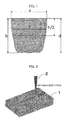
- FIG. 1 is a view showing a cross-sectional shape of a weld bead as viewed from the welding direction.
- a surface width of the weld bead (molten pool) is a
- a penetration depth at a central portion of the weld bead is d
- a maximum penetration depth of the weld bead is h
- a penetration width at a position where the penetration depth is h/2 is b.
- Both a depth of the keyhole and the maximum penetration depth of the weld bead are the depth from a surface of the workpiece 1.
- the same reference numerals show the same positions also in the following figures.
- FIG. 6 shows a cross-sectional shape of the keyhole and molten pool in a process of advancing the laser beam in the welding direction while rotating the beam at a high speed. Since a tip of a laser beam 2 draws a circle, the keyhole is also formed outside a center of the beam, and thus it is possible to form the molten pool having a surface width "a" larger than that of a conventional welding method in which the beam is not rotated.
- FIG. 7 shows a cross-sectional shape of the keyhole and molten pool as viewed from the welding direction.
- the depth of a keyhole 4 is the same as the maximum penetration depth h of the molten pool. That is, the depth of the keyhole 4 is equal to the maximum penetration depth of the molten pool. Since the laser beam 3 is advanced in the welding direction while being rotated at the high speed, a rotation diameter (distance between the keyholes) of the keyhole is equal to a beam rotation diameter e, and a position where the molten pool is deepest is a position shifted by e/2 outwardly from a center of the molten pool.
- the beam rotation speed is very high, for example, the beam rotation diameter is 2.0 mm, rotation frequency is 100 Hz, and a scanner speed of the beam is 600 mm/s or more, the beam rotation speed is twelve times forward speed (welding speed) of the laser beam in the welding direction.
- the cross-sectional shape of the molten pool taken along a direction perpendicular to the welding direction is convex downward at two positions spaced outwardly from a center of a bottom of the molten pool.
- the rotation speed of the laser beam is much faster than the forward speed in the welding direction, it is possible to reduce an amount of the molten pool in front of the keyhole with respect to a direction (spiral direction of a combination of a linear welding direction and a rotation direction) of movement of the laser beam, and thus the surface width "a" of the molten pool is not much wider than the rotation diameter of the keyhole. That is, width variation from the surface to the bottom of the molten pool is smaller than that of the conventional welding method.
- the rotation speed of the laser beam is very high, a time that the molten pool behind the keyhole flows back to an opening of the keyhole is short, and the opening is hardly closed.
- the keyhole does not move linearly but moves rotationally with respect to a traveling direction of the laser beam, the molten pool also flows in accordance with a rotation direction of the keyhole. However, a flow of the molten pool stays for a certain time due to its inertia, and receives stirring effect of the keyhole formed by irradiation with the laser beam.
- a concave is formed in the opening of the keyhole in a rearward direction of movement of the keyhole, and it is possible to avoid direct irradiation of the laser beam to a surface of the molten pool and to directly irradiate the laser beam to a lower portion of the keyhole, thereby preventing intense vaporization of the molten metal around the opening of the keyhole, and thereby preventing spatter generation.
- shape of the weld bead welded under the welding conditions of the present embodiment is such that (i) when the maximum penetration depth of the weld bead cross section is h, a relationship between the surface width "a" of the weld bead and the penetration width "b" at the position where the penetration depth is h/2 is b/a > 0.6, (ii) a relationship between the maximum penetration depth h and the penetration depth d at a center position of the weld bead is h/d > 1.0, and (iii) a relationship between the bead surface width "a" and the maximum penetration depth h of the weld bead cross section is h/a ⁇ 3.0.
- the laser power is 200 W to 1000 W
- the beam spot diameter is 0.04 mm to 0.2 mm
- the welding speed is 10 mm/s to 100 mm/s
- the flow rate of the shielding gas is 5.0 l/min to 30.0 l/min.
- FIG. 4 An example of a cross-sectional shape of the bead welded under the welding conditions described above is shown in FIG. 4 .
- the weld bead shape is such that the surface width "a" is at least twice the penetration width "b", a position where the penetration depth is deepest is the central portion of the weld bead, and the weld bead has a wine cup shape. Further, a large amount of spatter is generated in a welding process.
- a lap welded joint according to the present embodiment is, for example, a butt joint (not shown) of copper plate having a thickness of 1.0 mm.
- a visible light and near-infrared laser having a wavelength of 500 nm to 880 nm can be used, but a laser beam of another wavelength may also be used.
- the laser beam is generated from the laser oscillator (not shown), and is condensed by the beam scanner and the condenser lens (not shown) through the transport channel, to be irradiated to a surface of the butt joint of copper plate described above.
- the welding is performed by advancing the laser welding head including the beam scanner in the welding direction.
- Ar argon
- the shielding gas is not limited to Ar, and He (helium) or a mixture thereof may be used.
- the laser power is 200 W to 800 W
- the beam spot diameter is 0.04 mm to 0.2 mm
- the number of repetitions of beam rotation is 300 Hz to 1000 Hz
- the beam rotation diameter is 0.2 mm to 3.0 mm.
- the welding speed is 10 mm/s to 100 mm/s
- the flow rate of the shielding gas is 5.0 l/min to 30.0 l/min.
- FIG. 8 shows a cross-sectional shape of the bead welded under the welding conditions described above.
- the relationship between the bead surface width "a" and the maximum penetration depth h of the weld bead cross section is h/a ⁇ 3.0.
- FIG. 9 shows a relationship between the number of repetitions (frequency) of beam rotation and the number of spatter generations.
- FIG. 10 shows a relationship between the beam rotation diameter and the number of spatter generations. From the figures, when the frequency of beam rotation is 60Hz to 900Hz, and the beam rotation diameter is 0.2 mm to 2.6mm, it is found that it is possible to halve the number of spatters than that of the conventional method.
Landscapes
- Physics & Mathematics (AREA)
- Optics & Photonics (AREA)
- Engineering & Computer Science (AREA)
- Plasma & Fusion (AREA)
- Mechanical Engineering (AREA)
- Laser Beam Processing (AREA)
Applications Claiming Priority (1)
| Application Number | Priority Date | Filing Date | Title |
|---|---|---|---|
| PCT/JP2014/050731 WO2015107664A1 (fr) | 2014-01-17 | 2014-01-17 | Procédé de soudage au laser et jonction soudée |
Publications (2)
| Publication Number | Publication Date |
|---|---|
| EP3095548A1 true EP3095548A1 (fr) | 2016-11-23 |
| EP3095548A4 EP3095548A4 (fr) | 2017-09-27 |
Family
ID=53542583
Family Applications (1)
| Application Number | Title | Priority Date | Filing Date |
|---|---|---|---|
| EP14879130.4A Withdrawn EP3095548A4 (fr) | 2014-01-17 | 2014-01-17 | Procédé de soudage au laser et jonction soudée |
Country Status (5)
| Country | Link |
|---|---|
| US (1) | US20160325377A1 (fr) |
| EP (1) | EP3095548A4 (fr) |
| JP (1) | JP6158356B2 (fr) |
| CN (1) | CN105916627B (fr) |
| WO (1) | WO2015107664A1 (fr) |
Cited By (1)
| Publication number | Priority date | Publication date | Assignee | Title |
|---|---|---|---|---|
| WO2018144524A1 (fr) | 2017-01-31 | 2018-08-09 | Nuburu Inc. | Procédés et systèmes de soudage de cuivre à l'aide de laser bleu |
Families Citing this family (11)
| Publication number | Priority date | Publication date | Assignee | Title |
|---|---|---|---|---|
| JP6725351B2 (ja) * | 2016-07-14 | 2020-07-15 | 株式会社Gsユアサ | 蓄電素子及び蓄電素子の製造方法 |
| JP6777023B2 (ja) * | 2017-06-20 | 2020-10-28 | トヨタ自動車株式会社 | 積層金属箔の溶接方法 |
| DE102017120051B4 (de) * | 2017-08-31 | 2023-01-12 | Baosteel Tailored Blanks Gmbh | Verfahren zum Laserstrahlschweißen eines oder mehrerer Stahlbleche aus presshärtbarem Mangan-Borstahl |
| JP7165073B2 (ja) * | 2019-02-20 | 2022-11-02 | 株式会社東芝 | ダイカスト部材のレーザ溶接方法及びダイカスト製品の製造方法 |
| CN109708783B (zh) * | 2019-02-22 | 2023-09-01 | 无锡昆仑富士仪表有限公司 | 一种耐腐蚀金属薄膜片组件的激光焊接方法 |
| DE102019131906A1 (de) * | 2019-11-26 | 2021-05-27 | Voestalpine Automotive Components Linz Gmbh | Verfahren zum Verschweißen beschichteter Stahlbleche |
| FR3109192B1 (fr) * | 2020-04-09 | 2022-03-18 | Valeo Emrayages | Système d’accouplement pour un engin de mobilité |
| CN111843204A (zh) * | 2020-06-22 | 2020-10-30 | 河海大学常州校区 | 一种基于细化焊缝晶粒的Ti2AlNb基合金激光焊接方法 |
| JP7609652B2 (ja) * | 2021-02-19 | 2025-01-07 | 株式会社神戸製鋼所 | 銅合金板の接合方法及び銅合金板の接合体 |
| CN114523203B (zh) * | 2022-03-13 | 2022-11-29 | 扬州沃盛车业制造有限公司 | 一种激光智能焊接方法及系统 |
| CN119407323A (zh) * | 2024-11-13 | 2025-02-11 | 北京工业大学 | 外层激光束围绕型旋转辅助高功率激光的复合焊接方法 |
Family Cites Families (34)
| Publication number | Priority date | Publication date | Assignee | Title |
|---|---|---|---|---|
| US3688080A (en) * | 1969-09-08 | 1972-08-29 | Andrew John Cartwright | Welding |
| US4000392A (en) * | 1974-07-01 | 1976-12-28 | United Technologies Corporation | Fusion zone purification by controlled laser welding |
| US4019018A (en) * | 1974-09-30 | 1977-04-19 | Kobe Steel Ltd. | Process for narrow gap welding of aluminum alloy thick plates |
| US4163869A (en) * | 1977-11-02 | 1979-08-07 | Westinghouse Electric Corp. | Electrical connection between aluminum conductors |
| IT1179064B (it) * | 1984-08-20 | 1987-09-16 | Fiat Auto Spa | Procedimento di saldatura di lamiere |
| US4782206A (en) * | 1987-01-27 | 1988-11-01 | The Babcock & Wilcox Company | Method and apparatus for controlling weld bead shape to eliminate microfissure defects when shape melting austenitic materials |
| JPS6422488A (en) * | 1987-07-20 | 1989-01-25 | Toshiba Corp | Laser beam welding method |
| JPH11156579A (ja) * | 1996-11-15 | 1999-06-15 | Amada Co Ltd | レーザー切断方法、レーザーピアス方法、レーザー溶接方法、およびレーザー加飾方法並びに前記各方法に使用するレーザー加工ヘッド |
| US20010047988A1 (en) * | 1997-10-20 | 2001-12-06 | Kazuo Hiraoka | Welding method and welded joint structure |
| JP2001030089A (ja) * | 1999-07-19 | 2001-02-06 | Sumitomo Electric Ind Ltd | レーザ溶接方法 |
| US6521861B2 (en) * | 2000-02-07 | 2003-02-18 | General Electric Company | Method and apparatus for increasing welding rate for high aspect ratio welds |
| JP4150907B2 (ja) * | 2001-02-19 | 2008-09-17 | トヨタ自動車株式会社 | レーザ加工装置およびその加工方法 |
| US6740845B2 (en) * | 2002-05-24 | 2004-05-25 | Alcoa Inc. | Laser welding with beam oscillation |
| US6828526B1 (en) * | 2003-05-15 | 2004-12-07 | Alcoa Inc. | Gas metal buried arc welding of lap-penetration joints |
| JP2004340874A (ja) * | 2003-05-19 | 2004-12-02 | Hitachi Ltd | 中性子吸収棒及び端栓溶接方法並びに溶接装置 |
| US7154064B2 (en) * | 2003-12-08 | 2006-12-26 | General Motors Corporation | Method of improving weld quality |
| US20060011592A1 (en) * | 2004-07-14 | 2006-01-19 | Pei-Chung Wang | Laser welding control |
| JP2006075853A (ja) * | 2004-09-08 | 2006-03-23 | Sumitomo Metal Ind Ltd | オーステナイト系合金鋼のレーザ溶接継手およびその製造方法 |
| JP2007319878A (ja) * | 2006-05-31 | 2007-12-13 | Mitsubishi Heavy Ind Ltd | レーザ加工装置及びレーザ加工方法 |
| JP5061670B2 (ja) * | 2007-03-15 | 2012-10-31 | Jfeスチール株式会社 | レーザ溶接方法 |
| DE102007038502B4 (de) * | 2007-08-14 | 2013-01-03 | Fraunhofer-Gesellschaft zur Förderung der angewandten Forschung e.V. | Verfahren zum Fügen von mindestens zwei Werkstücken mittels eines Laserstrahls |
| US20090314757A1 (en) * | 2008-06-18 | 2009-12-24 | Caterpillar Inc. | Thick gage welding |
| WO2010137186A1 (fr) * | 2009-05-27 | 2010-12-02 | Jfeスチール株式会社 | Procédé de soudage sous flux en poudre pour plaque en acier |
| DK2508290T3 (en) * | 2009-12-04 | 2017-04-10 | Nippon Steel & Sumitomo Metal Corp | STUFF WASTE COLLECTION AND PROCEDURE FOR PREPARING THIS |
| RU2518654C2 (ru) * | 2010-01-20 | 2014-06-10 | Кабусики Кайся Тосиба | Труба с двойными стенками, способ изготовления трубы с двойными стенками и парогенератор |
| JP5827454B2 (ja) * | 2010-03-08 | 2015-12-02 | 株式会社神戸製鋼所 | レーザー・アーク複合溶接方法及び該溶接方法による溶接部材の製造方法 |
| JP4903918B1 (ja) * | 2010-06-07 | 2012-03-28 | 新日本製鐵株式会社 | 超高強度溶接継手およびその製造方法 |
| JP5609632B2 (ja) * | 2010-12-27 | 2014-10-22 | スズキ株式会社 | レーザ重ね溶接方法 |
| EP2478990B1 (fr) | 2011-01-21 | 2019-04-17 | Leister Technologies AG | Procédé de réglage d'un spot de lumière laser pour le traitement laser de pièces et dispositif destiné à l'exécution du procédé |
| US20130000121A1 (en) * | 2011-06-30 | 2013-01-03 | Gregory Mark Burgess | Spherical cutter and method for machining a curved slot |
| EP2594357A1 (fr) * | 2011-11-16 | 2013-05-22 | Optec S.p.A. | Dispositif et procédé pour souder au laser avec une unité de calibration avec des éléments réfractants |
| EP2925481B1 (fr) * | 2012-11-30 | 2016-09-21 | DirectPhotonics Industries GmbH | Procédé et dispositif de traitement de matériau par rayons laser |
| KR102049445B1 (ko) * | 2013-05-31 | 2019-11-28 | 삼성디스플레이 주식회사 | 레이저 빔 조사 장치 및 이를 이용한 유기 발광 디스플레이 장치의 제조 방법 |
| US9381292B2 (en) * | 2014-07-24 | 2016-07-05 | Kamal Ahmed ALJOHANI | Diabetes regulator |
-
2014
- 2014-01-17 WO PCT/JP2014/050731 patent/WO2015107664A1/fr not_active Ceased
- 2014-01-17 US US15/110,250 patent/US20160325377A1/en not_active Abandoned
- 2014-01-17 EP EP14879130.4A patent/EP3095548A4/fr not_active Withdrawn
- 2014-01-17 JP JP2015557643A patent/JP6158356B2/ja not_active Expired - Fee Related
- 2014-01-17 CN CN201480073272.2A patent/CN105916627B/zh not_active Expired - Fee Related
Cited By (2)
| Publication number | Priority date | Publication date | Assignee | Title |
|---|---|---|---|---|
| WO2018144524A1 (fr) | 2017-01-31 | 2018-08-09 | Nuburu Inc. | Procédés et systèmes de soudage de cuivre à l'aide de laser bleu |
| EP3576899A4 (fr) * | 2017-01-31 | 2021-02-24 | Nuburu, Inc. | Procédés et systèmes de soudage de cuivre à l'aide de laser bleu |
Also Published As
| Publication number | Publication date |
|---|---|
| US20160325377A1 (en) | 2016-11-10 |
| JPWO2015107664A1 (ja) | 2017-03-23 |
| WO2015107664A1 (fr) | 2015-07-23 |
| EP3095548A4 (fr) | 2017-09-27 |
| CN105916627A (zh) | 2016-08-31 |
| JP6158356B2 (ja) | 2017-07-05 |
| CN105916627B (zh) | 2017-09-05 |
Similar Documents
| Publication | Publication Date | Title |
|---|---|---|
| EP3095548A1 (fr) | Procédé de soudage au laser et jonction soudée | |
| Xie | Dual beam laser welding | |
| Węglowski et al. | Electron beam welding–Techniques and trends–Review | |
| Zhang et al. | Optimization of deep penetration laser welding of thick stainless steel with a 10 kW fiber laser | |
| Kaplan et al. | Spatter in laser welding | |
| KR101436705B1 (ko) | 레이저·아크 복합 용접 방법 및 상기 용접 방법에 의한 용접 부재의 제조 방법 | |
| Horník et al. | Laser beam oscillation strategy for weld geometry variation | |
| US10328513B2 (en) | Welding process, welding system, and welded article | |
| US20120325786A1 (en) | Welding process and a welding arrangement | |
| Yang et al. | Influence of alternating magnetic field on microstructure and mechanical properties of laser-MIG hybrid welded HG785D steel joint | |
| WO2015189883A1 (fr) | Procédé de soudage au laser | |
| Cavilha Neto et al. | Assessment of power modulation formats on penetration depth for laser welding | |
| Naito et al. | Effect of oxygen in ambient atmosphere on penetration characteristics in single yttrium–aluminum–garnet laser and hybrid welding | |
| AU2005201860A1 (en) | Laser or laser/arc hybrid welding process with formation of a plasma on the backside | |
| Gao et al. | Weld microstructure and shape of laser–arc hybrid welding | |
| Naito et al. | Observation of keyhole behavior and melt flows during laser-arc hybrid welding | |
| Lienert et al. | Weld bead center line shift during laser welding of austenitic stainless steels with different sulfur content | |
| Zhao et al. | The energy synergistic mechanism of coaxial heterogeneous-wavelength hybrid laser beam and its effect on welding molten pool dynamics for aluminum alloy | |
| Bushma | State-of-the-art of hybrid laser-plasma welding | |
| JP2020015053A (ja) | 溶接方法、溶接装置、および溶接鋼板 | |
| Li et al. | Laser-Arc Hybrid Welding | |
| Wu et al. | Narrow groove laser-arc hybrid welding of thick-sectioned HSLA steel using laser beam oscillation | |
| Bunaziv | Optimization of parameters for fiber laser-MAG hybrid welding in shipbuilding applications | |
| Narikiyo et al. | Optimisation of welding using two Nd–YAG laser beams combined at workpiece surface | |
| Amiaga et al. | Development of a fast method for forming Braille on the surface of steels with IR nanosecond pulsed 50 W fiber laser |
Legal Events
| Date | Code | Title | Description |
|---|---|---|---|
| PUAI | Public reference made under article 153(3) epc to a published international application that has entered the european phase |
Free format text: ORIGINAL CODE: 0009012 |
|
| 17P | Request for examination filed |
Effective date: 20160817 |
|
| AK | Designated contracting states |
Kind code of ref document: A1 Designated state(s): AL AT BE BG CH CY CZ DE DK EE ES FI FR GB GR HR HU IE IS IT LI LT LU LV MC MK MT NL NO PL PT RO RS SE SI SK SM TR |
|
| AX | Request for extension of the european patent |
Extension state: BA ME |
|
| DAX | Request for extension of the european patent (deleted) | ||
| A4 | Supplementary search report drawn up and despatched |
Effective date: 20170828 |
|
| RIC1 | Information provided on ipc code assigned before grant |
Ipc: B23K 26/21 20140101AFI20170822BHEP Ipc: B23K 26/14 20140101ALI20170822BHEP Ipc: B23K 26/244 20140101ALI20170822BHEP Ipc: B23K 26/082 20140101ALI20170822BHEP Ipc: B23K 26/12 20140101ALI20170822BHEP Ipc: B23K 26/0622 20140101ALI20170822BHEP Ipc: B23K 103/04 20060101ALI20170822BHEP Ipc: B23K 26/32 20140101ALI20170822BHEP Ipc: B23K 103/00 20060101ALI20170822BHEP |
|
| STAA | Information on the status of an ep patent application or granted ep patent |
Free format text: STATUS: EXAMINATION IS IN PROGRESS |
|
| 17Q | First examination report despatched |
Effective date: 20201126 |
|
| STAA | Information on the status of an ep patent application or granted ep patent |
Free format text: STATUS: THE APPLICATION HAS BEEN WITHDRAWN |
|
| 18W | Application withdrawn |
Effective date: 20201229 |