EP3095937A1 - Raccordement de vantail de porte mobile - Google Patents
Raccordement de vantail de porte mobile Download PDFInfo
- Publication number
- EP3095937A1 EP3095937A1 EP16174395.0A EP16174395A EP3095937A1 EP 3095937 A1 EP3095937 A1 EP 3095937A1 EP 16174395 A EP16174395 A EP 16174395A EP 3095937 A1 EP3095937 A1 EP 3095937A1
- Authority
- EP
- European Patent Office
- Prior art keywords
- connection
- door leaf
- drive means
- movement point
- pendulum arm
- Prior art date
- Legal status (The legal status is an assumption and is not a legal conclusion. Google has not performed a legal analysis and makes no representation as to the accuracy of the status listed.)
- Granted
Links
Images


Classifications
-
- E—FIXED CONSTRUCTIONS
- E05—LOCKS; KEYS; WINDOW OR DOOR FITTINGS; SAFES
- E05D—HINGES OR SUSPENSION DEVICES FOR DOORS, WINDOWS OR WINGS
- E05D15/00—Suspension arrangements for wings
- E05D15/16—Suspension arrangements for wings for wings sliding vertically more or less in their own plane
- E05D15/24—Suspension arrangements for wings for wings sliding vertically more or less in their own plane consisting of parts connected at their edges
-
- E—FIXED CONSTRUCTIONS
- E05—LOCKS; KEYS; WINDOW OR DOOR FITTINGS; SAFES
- E05D—HINGES OR SUSPENSION DEVICES FOR DOORS, WINDOWS OR WINGS
- E05D15/00—Suspension arrangements for wings
- E05D15/16—Suspension arrangements for wings for wings sliding vertically more or less in their own plane
- E05D15/165—Details, e.g. sliding or rolling guides
-
- E—FIXED CONSTRUCTIONS
- E05—LOCKS; KEYS; WINDOW OR DOOR FITTINGS; SAFES
- E05F—DEVICES FOR MOVING WINGS INTO OPEN OR CLOSED POSITION; CHECKS FOR WINGS; WING FITTINGS NOT OTHERWISE PROVIDED FOR, CONCERNED WITH THE FUNCTIONING OF THE WING
- E05F15/00—Power-operated mechanisms for wings
- E05F15/60—Power-operated mechanisms for wings using electrical actuators
- E05F15/603—Power-operated mechanisms for wings using electrical actuators using rotary electromotors
- E05F15/665—Power-operated mechanisms for wings using electrical actuators using rotary electromotors for vertically-sliding wings
- E05F15/668—Power-operated mechanisms for wings using electrical actuators using rotary electromotors for vertically-sliding wings for overhead wings
- E05F15/681—Power-operated mechanisms for wings using electrical actuators using rotary electromotors for vertically-sliding wings for overhead wings operated by flexible elongated pulling elements, e.g. belts
-
- E—FIXED CONSTRUCTIONS
- E05—LOCKS; KEYS; WINDOW OR DOOR FITTINGS; SAFES
- E05Y—INDEXING SCHEME ASSOCIATED WITH SUBCLASSES E05D AND E05F, RELATING TO CONSTRUCTION ELEMENTS, ELECTRIC CONTROL, POWER SUPPLY, POWER SIGNAL OR TRANSMISSION, USER INTERFACES, MOUNTING OR COUPLING, DETAILS, ACCESSORIES, AUXILIARY OPERATIONS NOT OTHERWISE PROVIDED FOR, APPLICATION THEREOF
- E05Y2201/00—Constructional elements; Accessories therefor
- E05Y2201/60—Suspension or transmission members; Accessories therefor
- E05Y2201/622—Suspension or transmission members elements
- E05Y2201/686—Rods, links
-
- E—FIXED CONSTRUCTIONS
- E05—LOCKS; KEYS; WINDOW OR DOOR FITTINGS; SAFES
- E05Y—INDEXING SCHEME ASSOCIATED WITH SUBCLASSES E05D AND E05F, RELATING TO CONSTRUCTION ELEMENTS, ELECTRIC CONTROL, POWER SUPPLY, POWER SIGNAL OR TRANSMISSION, USER INTERFACES, MOUNTING OR COUPLING, DETAILS, ACCESSORIES, AUXILIARY OPERATIONS NOT OTHERWISE PROVIDED FOR, APPLICATION THEREOF
- E05Y2600/00—Mounting or coupling arrangements for elements provided for in this subclass
- E05Y2600/10—Adjustable
- E05Y2600/12—Adjustable by manual operation
-
- E—FIXED CONSTRUCTIONS
- E05—LOCKS; KEYS; WINDOW OR DOOR FITTINGS; SAFES
- E05Y—INDEXING SCHEME ASSOCIATED WITH SUBCLASSES E05D AND E05F, RELATING TO CONSTRUCTION ELEMENTS, ELECTRIC CONTROL, POWER SUPPLY, POWER SIGNAL OR TRANSMISSION, USER INTERFACES, MOUNTING OR COUPLING, DETAILS, ACCESSORIES, AUXILIARY OPERATIONS NOT OTHERWISE PROVIDED FOR, APPLICATION THEREOF
- E05Y2900/00—Application of doors, windows, wings or fittings thereof
- E05Y2900/10—Application of doors, windows, wings or fittings thereof for buildings or parts thereof
- E05Y2900/106—Application of doors, windows, wings or fittings thereof for buildings or parts thereof for garages
Definitions
- the invention relates to a connection for a portable door leaf, which is guided in lateral rails by means of rollers and is connected by connecting lever with a strand-shaped drive means.
- a sectional door for example, in the DE 10 2005 023 384 B3 described.
- This sectional door has a frame with guide rails and a Se Erasmusaltorblatt of individual, articulated interconnected sections, which are guided by rollers in lateral guide rails.
- Another sectional door which is guided in lateral guide rails and has lateral drive means in the form of chains, shows the EP 2 806 095 A1 ,
- the object of the invention is to carry out a connection of a guided in side rails locally variable door leaf so that easy adjustability during assembly for proper completion in the bottom area is taken care of. This adjustability should also be practicable in the installed state of the door leaf.
- bifilar refers to two, substantially flat pendulum arms, which are mounted between lateral drive means and the door leaf.
- a bifilar connection has the advantage that it has a statically determined position for the door leaf and yet contains in itself a sufficient mobility, which can also be referred to as a floating connection.
- the pendulum arms which are arranged on both sides in the lower region of the door leaf, essentially have two movement points.
- Such trained movement points are mobile and can in conjunction with rigid pendulum arms simplify the connection of a substantially vertically variable door leaf and also make it adjustable to a lower solid floor or the like.
- a movement point can be executed as a fulcrum, which allows a change in the pendulum arm at a connection, which is carried out at the lower end of the door leaf, more or less in the vertical direction.
- the free end of this pendulum arm is designed so that over a movement point a variable mounting with multiple degrees of freedom is performed on the laterally arranged, movable drive means.
- Such an all-round movable movement point can be installed directly in the pendulum arm, or be performed by an additional connecting element in conjunction with the pendulum.
- the door leaf can be adjusted via the pendulum arms and the pivot points in horizontal alignment. In this case, the lower end of the door leaf always remains after its adjustment in a same horizontal plane and does not change the distance to the stationary floor or a lower spar of a frame.
- the lower attachment of the pendulum arm also includes a movable attachment as the upper attachment in several degrees of freedom.
- This connection allows an even better adjustability and balancing of the door leaf. While the lower attachment can move in several degrees of freedom, this is not adjustable by itself.
- the upper attachment through the movement point is variable due to an adjustment. Due to the upper connections with the movement points, it is possible to adjust the position of the movement points continuously and steplessly vertically by means of the adjusting device.
- Such an adjusting device makes it possible to that during assembly an absolute parallelism of the lower portion of the door leaf to the floor can be produced. This guarantees in any case a good closed position of the door leaf in its closed position. This closing position is always maintained, even if the door leaf is lifted by the lateral drive means and then lowered again.
- the suspension points of the connection which can be moved in several degrees of freedom, can also include a ball joint connection.
- a bifilar connection is particularly suitable for sectional doors or overhead doors that are operated without weight compensation device.
- the installation of the door is much easier and shortens the assembly times. If readjustments are necessary during operation, they can be carried out quickly without dismantling the door leaf.
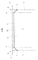
- FIG. 1 is reproduced in a schematic diagram of the lower part of a door leaf 1.
- the door leaf 1 is suspended on each side via pendulum arms 9.
- Such a pendulum arm 9 has an upper movement point 3 and a lower connection 4, which are referred to collectively as connection 6.
- the connection 4 may be a pure fulcrum or an attachment with multiple degrees of freedom.
- a mobility of the pendulum arm 9 to the door leaf 1 is given only in one direction of movement.
- the movement point 3 is designed so that it is always formed in several directions of movement.
- the bifilar attachment 6 may be considered part of a substantially gimbal in one plane. In this case, a lower termination 26 of the door leaf 1 always maintains its parallelism to a bottom 5 after the adjustment.
- the movement point 3 is secured by means of drivers 13 to a strand-shaped drive means, not shown, which is variable within rails 2 or in separate rails in the vertical direction.
- a strand-shaped drive means not shown, which is variable within rails 2 or in separate rails in the vertical direction.
- the rails 2 have been shown in connection with drive rails 18, wherein between the vertical edges of the door leaf 1 and the drive rails 18, the connection 6 is arranged on each side.
- the drivers 13 are changed on each side of the door leaf by strand-shaped drive means in position, wherein the drive means are driven by a common drive.
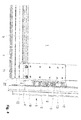
- connection 6 The placement of the bifilar connection 6 on both sides in the lower end of the door panel 1, the FIG. 3 be taken in a perspective view.
- a seal 7 for sealing against the bottom 5 is present at the lower end 26.
- the connections 6 In the area of the closure 26, the connections 6 have been arranged on each side.
- the connection 6 may also at the same time a holder for a lower roller 14, which guarantees a proper guidance of the door leaf 1 in the rails 2, have.
- the roller 14 is mounted via a roller axle 10 within a roller bearing 11.
- connection 6 is arranged with the pendulum arm 9 between the vertical edge of the door leaf 1 and a panel 8 and the running rail 2.
- the pendulum arm 9 is connected at its upper free end with the movement point 3, which is movably mounted within or on the driver 13.
- a base 12 is provided, via which the connection to the panel 8 is ensured by screw connections, not shown.
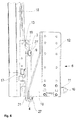
- connection 6 By the individual representation of the connection 6 after FIG. 5 It is clear that, following the base 12 angled sideways side 16 is present. Within the side part 16, in a preferred embodiment, the compound 4 is included as a rotary connection with a screw, which in particular also the FIG. 6 can be removed.
- the movement point 3 at the upper end of the pendulum arm 9 is formed by a connecting element 19, which allows a mobility of the pendulum arm 9 in several degrees of freedom or at least in two planes.
- roller bearing 11 can be removed, which is penetrated by the roller shaft 10 and is changeable in the axial direction within the roller bearing 11 and can thus adjust in the running rail 2 whose course.
- the roller bearing 11 is fastened via fasteners 20 to the base 12.
- FIG. 7 This arrangement can also be shown FIG. 7 be removed.
- the connecting element 19 after FIG. 8 is fixed end in the pendulum arm 9 opposite a projecting collar 25, wherein within the connecting element 19, a thread 24 is present.
- the central region of the connecting element 19 is characterized by a round or convex projection 22.
- in the Connection thereto is at the end a collar 21, which causes a captive from the driver 13 by a fixing 15 after insertion into the driver 13. Due to the design of the projection 22, the pendulum arm 9 can thus move in several directions and thus make the entire door leaf 1 adjustable.
- an adjusting device 17 is disposed within or on the driver 13.
- FIG. 9 The location of the pendulum arm 9 between the right-side design of the driver 13 and the left-hand boundary through the base 12 can be very clear FIG. 9 be removed.
- the movement point 3 has been performed with the connecting element 19 on the driver 13, wherein the outer end forms a screw 27.
- the connecting element 19 in the connection 4 has also been carried out at the lower end of the pendulum arm 9. This shows that the collar 21 rests against the outer surface on the left side of the pendulum arm 9.
- the fixing of the connecting element 19 relative to the side part 16 is also achieved here by a screw 27.
- the base 12 with the door leaf 1, not shown here is designed as a floating suspension by the bifilar connection 6 in relation to the left side with the driver 13 and on the right side.
- the closure 26 can be accurately adjusted by means of the floating bearing.
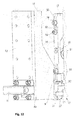
- the driver 13 In a single presentation after FIG. 10 the driver 13 is shown.
- the driver 13 essentially consists of a base body 37, which has long holes 30 in the upper part for fastening.
- a spreading arm 40 on the base body 37 a receptacle 29 for the connecting element 19 is created.
- This receptacle 29 is open, so that there the movement point 3 can be used in its execution with the connecting element 19.
- the collar 21 bears against a surface of the main body 37.
- a safety device 28 is present in order for the pendulum arm 9, which is inserted into the receptacle 29 via the connecting element 19, to maintain its position.
- This fuse 28 can be realized by a screw.
- the adjusting device 17 has a holding piece 35 which does not have a mounting surface 41 at a shown roller carriage or the like for the strand-shaped drive means with screws 36 can be attached.
- a recess 34 which is designed so that the head of a nut 32 is secured against rotation.
- the holding piece 35 is thereby penetrated by an adjusting element 31, wherein the adjusting element 31 starts with its end after penetration by a nut 32 against a contact surface 33 of the driver 13.
- By rotational movements of the actuating element 13 thus the driver 13 in its position and thus simultaneously the associated pendulum 9 are changed.
- the driver 13 is fixed via screw 39 through the slots 30.
- a fuse 42 the nut 32 is also set against unintentional release.
- the fuse 42 may for example also consist of a lock nut.
- connection 19 is a connection which can be moved in several degrees of freedom, by means of which, in interaction with the connection 4, the end 26 can execute a precise balancing with respect to the floor 5. This is achieved in that a floating, but static stable attachment of the door leaf 1 is achieved by the two-sided versions of the connection 6.
- FIG. 12 can be clarified in a rear view again an insight of the interaction of the driver 13 and the adjusting device 17.
- the actuator 31 presses against the Anstell Structure 33 of the driver 13 and thus 31, a lower end 43 of the base 12 can be changed in its relative position with a change in position of the actuating element. After the adjustment is achieved via the engaging in the slots 30 screw 39 fixing the driver 13.
- the door leaf 1 may be part of a sectional door or a spiral door or a high-speed door or a tipping door.
Landscapes
- Engineering & Computer Science (AREA)
- Mechanical Engineering (AREA)
- Power-Operated Mechanisms For Wings (AREA)
Priority Applications (1)
| Application Number | Priority Date | Filing Date | Title |
|---|---|---|---|
| PL16174395T PL3095937T3 (pl) | 2015-01-16 | 2016-01-15 | Przyłącze dla skrzydła bramy o zmiennym położeniu |
Applications Claiming Priority (2)
| Application Number | Priority Date | Filing Date | Title |
|---|---|---|---|
| DE102015100619.7A DE102015100619A1 (de) | 2015-01-16 | 2015-01-16 | Anbindung |
| EP16151472.4 | 2016-01-15 |
Related Parent Applications (1)
| Application Number | Title | Priority Date | Filing Date |
|---|---|---|---|
| EP16151472.4 Division | 2015-01-16 | 2016-01-15 |
Publications (2)
| Publication Number | Publication Date |
|---|---|
| EP3095937A1 true EP3095937A1 (fr) | 2016-11-23 |
| EP3095937B1 EP3095937B1 (fr) | 2020-03-04 |
Family
ID=55168188
Family Applications (1)
| Application Number | Title | Priority Date | Filing Date |
|---|---|---|---|
| EP16174395.0A Active EP3095937B1 (fr) | 2015-01-16 | 2016-01-15 | Raccordement de vantail de porte mobile |
Country Status (5)
| Country | Link |
|---|---|
| EP (1) | EP3095937B1 (fr) |
| DE (1) | DE102015100619A1 (fr) |
| DK (1) | DK3095937T3 (fr) |
| ES (1) | ES2788729T3 (fr) |
| PL (1) | PL3095937T3 (fr) |
Cited By (1)
| Publication number | Priority date | Publication date | Assignee | Title |
|---|---|---|---|---|
| CN108798341A (zh) * | 2018-05-25 | 2018-11-13 | 深圳市鑫成泰科技有限公司 | 一种密封门启合机构 |
Citations (4)
| Publication number | Priority date | Publication date | Assignee | Title |
|---|---|---|---|---|
| DE102005023384A1 (de) | 2005-05-17 | 2006-11-23 | Emitec Gesellschaft Für Emissionstechnologie Mbh | Verfahren und Vorrichtung zum Verschweißen metallischer Fasern zu einem Vließ |
| DE202012012514U1 (de) | 2012-02-22 | 2013-04-15 | Alpha Deuren International Bv | Spiraltor |
| US20140231030A1 (en) * | 2011-08-03 | 2014-08-21 | Daylee Pty Ltd. | Garage door drive apparatus |
| EP2806095A1 (fr) | 2013-05-24 | 2014-11-26 | Tseng, Li-Yu | Volant roulant de protection contre les inondations à détection automatique avec colonne renforcée à localisation automatique |
-
2015
- 2015-01-16 DE DE102015100619.7A patent/DE102015100619A1/de not_active Ceased
-
2016
- 2016-01-15 ES ES16174395T patent/ES2788729T3/es active Active
- 2016-01-15 DK DK16174395.0T patent/DK3095937T3/da active
- 2016-01-15 EP EP16174395.0A patent/EP3095937B1/fr active Active
- 2016-01-15 PL PL16174395T patent/PL3095937T3/pl unknown
Patent Citations (4)
| Publication number | Priority date | Publication date | Assignee | Title |
|---|---|---|---|---|
| DE102005023384A1 (de) | 2005-05-17 | 2006-11-23 | Emitec Gesellschaft Für Emissionstechnologie Mbh | Verfahren und Vorrichtung zum Verschweißen metallischer Fasern zu einem Vließ |
| US20140231030A1 (en) * | 2011-08-03 | 2014-08-21 | Daylee Pty Ltd. | Garage door drive apparatus |
| DE202012012514U1 (de) | 2012-02-22 | 2013-04-15 | Alpha Deuren International Bv | Spiraltor |
| EP2806095A1 (fr) | 2013-05-24 | 2014-11-26 | Tseng, Li-Yu | Volant roulant de protection contre les inondations à détection automatique avec colonne renforcée à localisation automatique |
Cited By (1)
| Publication number | Priority date | Publication date | Assignee | Title |
|---|---|---|---|---|
| CN108798341A (zh) * | 2018-05-25 | 2018-11-13 | 深圳市鑫成泰科技有限公司 | 一种密封门启合机构 |
Also Published As
| Publication number | Publication date |
|---|---|
| DK3095937T3 (da) | 2020-06-02 |
| DE102015100619A1 (de) | 2016-07-21 |
| PL3095937T3 (pl) | 2020-08-24 |
| ES2788729T3 (es) | 2020-10-22 |
| EP3095937B1 (fr) | 2020-03-04 |
Similar Documents
| Publication | Publication Date | Title |
|---|---|---|
| AT519903B1 (de) | Schiene zur Führung eines Schlittens einer Möbeltüre | |
| WO1998030776A1 (fr) | Porte articulee au plafond pour hauteurs de chute particulierement faibles | |
| EP2754813B1 (fr) | Charnière, notamment pour portes et fenêtres en plastique | |
| EP3175068B1 (fr) | Système de ferrure | |
| DE3904210C2 (fr) | ||
| EP3670805B1 (fr) | Ferrures de terminaison pour chaîne de poussée | |
| EP3095937A1 (fr) | Raccordement de vantail de porte mobile | |
| EP3577295B1 (fr) | Mécanisme d'entrainement pour meuble servant à déplacer une partie de meuble montée mobile | |
| DE102008006800B4 (de) | Führungsvorrichtung für einen Schiebeflügel | |
| EP2740872B1 (fr) | Palier d'angle prévu pour l'agencement recouvert | |
| EP0531626A1 (fr) | Ferrure, en particulier pour des battants étant basculés et déplacés d'un plan vers un deuxième plan parallèle | |
| CH649341A5 (en) | Corner joint on a turn-and-tilt window or on a turn-and-tilt door | |
| DE8800862U1 (de) | Schiebetür | |
| DE102008028598A1 (de) | Insektenschutztür | |
| DE7520486U (de) | Ausstellvorrichtung für aus Metalloder Kunststoffprofilen zusammengesetzte Fenster und Türen o.dgl | |
| EP3301249B1 (fr) | Dispositif d'étanchéité doté d'une barre d'étanchéité mobile | |
| EP3168399B1 (fr) | Armoire comprenant des profilés de cadre | |
| DE29600891U1 (de) | Sicherungseinrichtung | |
| DE8111079U1 (de) | Ecklager fuer fluegel von fenstern, tueren od. dgl. | |
| DE3416035C2 (fr) | ||
| DE2064047A1 (de) | Vorrichtung zur Feineinstellung von Dreh Kipp Fenstern | |
| DE10306921B3 (de) | Duschtürbeschlag | |
| EP1106763A1 (fr) | Penture pour portes, fenêtres ou telles | |
| EP1245177A2 (fr) | Montage pivotant d'une porte | |
| EP3379013A1 (fr) | Dispositif de guidage réglable pour un élément coulissant |
Legal Events
| Date | Code | Title | Description |
|---|---|---|---|
| PUAI | Public reference made under article 153(3) epc to a published international application that has entered the european phase |
Free format text: ORIGINAL CODE: 0009012 |
|
| AK | Designated contracting states |
Kind code of ref document: A1 Designated state(s): AL AT BE BG CH CY CZ DE DK EE ES FI FR GB GR HR HU IE IS IT LI LT LU LV MC MK MT NL NO PL PT RO RS SE SI SK SM TR |
|
| AX | Request for extension of the european patent |
Extension state: BA ME |
|
| STAA | Information on the status of an ep patent application or granted ep patent |
Free format text: STATUS: REQUEST FOR EXAMINATION WAS MADE |
|
| 17P | Request for examination filed |
Effective date: 20170523 |
|
| RBV | Designated contracting states (corrected) |
Designated state(s): AL AT BE BG CH CY CZ DE DK EE ES FI FR GB GR HR HU IE IS IT LI LT LU LV MC MK MT NL NO PL PT RO RS SE SI SK SM TR |
|
| STAA | Information on the status of an ep patent application or granted ep patent |
Free format text: STATUS: EXAMINATION IS IN PROGRESS |
|
| 17Q | First examination report despatched |
Effective date: 20171124 |
|
| APBK | Appeal reference recorded |
Free format text: ORIGINAL CODE: EPIDOSNREFNE |
|
| APBN | Date of receipt of notice of appeal recorded |
Free format text: ORIGINAL CODE: EPIDOSNNOA2E |
|
| APBR | Date of receipt of statement of grounds of appeal recorded |
Free format text: ORIGINAL CODE: EPIDOSNNOA3E |
|
| APBV | Interlocutory revision of appeal recorded |
Free format text: ORIGINAL CODE: EPIDOSNIRAPE |
|
| GRAP | Despatch of communication of intention to grant a patent |
Free format text: ORIGINAL CODE: EPIDOSNIGR1 |
|
| STAA | Information on the status of an ep patent application or granted ep patent |
Free format text: STATUS: GRANT OF PATENT IS INTENDED |
|
| INTG | Intention to grant announced |
Effective date: 20191001 |
|
| GRAS | Grant fee paid |
Free format text: ORIGINAL CODE: EPIDOSNIGR3 |
|
| GRAA | (expected) grant |
Free format text: ORIGINAL CODE: 0009210 |
|
| STAA | Information on the status of an ep patent application or granted ep patent |
Free format text: STATUS: THE PATENT HAS BEEN GRANTED |
|
| AK | Designated contracting states |
Kind code of ref document: B1 Designated state(s): AL AT BE BG CH CY CZ DE DK EE ES FI FR GB GR HR HU IE IS IT LI LT LU LV MC MK MT NL NO PL PT RO RS SE SI SK SM TR |
|
| REG | Reference to a national code |
Ref country code: GB Ref legal event code: FG4D Free format text: NOT ENGLISH |
|
| REG | Reference to a national code |
Ref country code: FI Ref legal event code: FGE |
|
| REG | Reference to a national code |
Ref country code: CH Ref legal event code: EP |
|
| REG | Reference to a national code |
Ref country code: AT Ref legal event code: REF Ref document number: 1240535 Country of ref document: AT Kind code of ref document: T Effective date: 20200315 |
|
| REG | Reference to a national code |
Ref country code: DE Ref legal event code: R096 Ref document number: 502016008993 Country of ref document: DE |
|
| REG | Reference to a national code |
Ref country code: IE Ref legal event code: FG4D Free format text: LANGUAGE OF EP DOCUMENT: GERMAN |
|
| REG | Reference to a national code |
Ref country code: SE Ref legal event code: TRGR |
|
| REG | Reference to a national code |
Ref country code: DK Ref legal event code: T3 Effective date: 20200528 |
|
| REG | Reference to a national code |
Ref country code: NL Ref legal event code: FP |
|
| REG | Reference to a national code |
Ref country code: CH Ref legal event code: NV Representative=s name: AMMANN PATENTANWAELTE AG BERN, CH |
|
| REG | Reference to a national code |
Ref country code: NO Ref legal event code: T2 Effective date: 20200304 |
|
| PG25 | Lapsed in a contracting state [announced via postgrant information from national office to epo] |
Ref country code: RS Free format text: LAPSE BECAUSE OF FAILURE TO SUBMIT A TRANSLATION OF THE DESCRIPTION OR TO PAY THE FEE WITHIN THE PRESCRIBED TIME-LIMIT Effective date: 20200304 |
|
| PG25 | Lapsed in a contracting state [announced via postgrant information from national office to epo] |
Ref country code: LV Free format text: LAPSE BECAUSE OF FAILURE TO SUBMIT A TRANSLATION OF THE DESCRIPTION OR TO PAY THE FEE WITHIN THE PRESCRIBED TIME-LIMIT Effective date: 20200304 Ref country code: HR Free format text: LAPSE BECAUSE OF FAILURE TO SUBMIT A TRANSLATION OF THE DESCRIPTION OR TO PAY THE FEE WITHIN THE PRESCRIBED TIME-LIMIT Effective date: 20200304 Ref country code: BG Free format text: LAPSE BECAUSE OF FAILURE TO SUBMIT A TRANSLATION OF THE DESCRIPTION OR TO PAY THE FEE WITHIN THE PRESCRIBED TIME-LIMIT Effective date: 20200604 |
|
| REG | Reference to a national code |
Ref country code: LT Ref legal event code: MG4D |
|
| REG | Reference to a national code |
Ref country code: ES Ref legal event code: FG2A Ref document number: 2788729 Country of ref document: ES Kind code of ref document: T3 Effective date: 20201022 |
|
| PG25 | Lapsed in a contracting state [announced via postgrant information from national office to epo] |
Ref country code: LT Free format text: LAPSE BECAUSE OF FAILURE TO SUBMIT A TRANSLATION OF THE DESCRIPTION OR TO PAY THE FEE WITHIN THE PRESCRIBED TIME-LIMIT Effective date: 20200304 Ref country code: PT Free format text: LAPSE BECAUSE OF FAILURE TO SUBMIT A TRANSLATION OF THE DESCRIPTION OR TO PAY THE FEE WITHIN THE PRESCRIBED TIME-LIMIT Effective date: 20200729 Ref country code: EE Free format text: LAPSE BECAUSE OF FAILURE TO SUBMIT A TRANSLATION OF THE DESCRIPTION OR TO PAY THE FEE WITHIN THE PRESCRIBED TIME-LIMIT Effective date: 20200304 Ref country code: SM Free format text: LAPSE BECAUSE OF FAILURE TO SUBMIT A TRANSLATION OF THE DESCRIPTION OR TO PAY THE FEE WITHIN THE PRESCRIBED TIME-LIMIT Effective date: 20200304 Ref country code: RO Free format text: LAPSE BECAUSE OF FAILURE TO SUBMIT A TRANSLATION OF THE DESCRIPTION OR TO PAY THE FEE WITHIN THE PRESCRIBED TIME-LIMIT Effective date: 20200304 Ref country code: IS Free format text: LAPSE BECAUSE OF FAILURE TO SUBMIT A TRANSLATION OF THE DESCRIPTION OR TO PAY THE FEE WITHIN THE PRESCRIBED TIME-LIMIT Effective date: 20200704 Ref country code: SK Free format text: LAPSE BECAUSE OF FAILURE TO SUBMIT A TRANSLATION OF THE DESCRIPTION OR TO PAY THE FEE WITHIN THE PRESCRIBED TIME-LIMIT Effective date: 20200304 |
|
| REG | Reference to a national code |
Ref country code: DE Ref legal event code: R097 Ref document number: 502016008993 Country of ref document: DE |
|
| PLBE | No opposition filed within time limit |
Free format text: ORIGINAL CODE: 0009261 |
|
| STAA | Information on the status of an ep patent application or granted ep patent |
Free format text: STATUS: NO OPPOSITION FILED WITHIN TIME LIMIT |
|
| PG25 | Lapsed in a contracting state [announced via postgrant information from national office to epo] |
Ref country code: IT Free format text: LAPSE BECAUSE OF FAILURE TO SUBMIT A TRANSLATION OF THE DESCRIPTION OR TO PAY THE FEE WITHIN THE PRESCRIBED TIME-LIMIT Effective date: 20200304 |
|
| 26N | No opposition filed |
Effective date: 20201207 |
|
| PG25 | Lapsed in a contracting state [announced via postgrant information from national office to epo] |
Ref country code: SI Free format text: LAPSE BECAUSE OF FAILURE TO SUBMIT A TRANSLATION OF THE DESCRIPTION OR TO PAY THE FEE WITHIN THE PRESCRIBED TIME-LIMIT Effective date: 20200304 |
|
| PG25 | Lapsed in a contracting state [announced via postgrant information from national office to epo] |
Ref country code: MC Free format text: LAPSE BECAUSE OF FAILURE TO SUBMIT A TRANSLATION OF THE DESCRIPTION OR TO PAY THE FEE WITHIN THE PRESCRIBED TIME-LIMIT Effective date: 20200304 |
|
| PG25 | Lapsed in a contracting state [announced via postgrant information from national office to epo] |
Ref country code: LU Free format text: LAPSE BECAUSE OF NON-PAYMENT OF DUE FEES Effective date: 20210115 |
|
| PG25 | Lapsed in a contracting state [announced via postgrant information from national office to epo] |
Ref country code: IE Free format text: LAPSE BECAUSE OF NON-PAYMENT OF DUE FEES Effective date: 20210115 |
|
| PG25 | Lapsed in a contracting state [announced via postgrant information from national office to epo] |
Ref country code: HU Free format text: LAPSE BECAUSE OF FAILURE TO SUBMIT A TRANSLATION OF THE DESCRIPTION OR TO PAY THE FEE WITHIN THE PRESCRIBED TIME-LIMIT; INVALID AB INITIO Effective date: 20160115 |
|
| PG25 | Lapsed in a contracting state [announced via postgrant information from national office to epo] |
Ref country code: CY Free format text: LAPSE BECAUSE OF FAILURE TO SUBMIT A TRANSLATION OF THE DESCRIPTION OR TO PAY THE FEE WITHIN THE PRESCRIBED TIME-LIMIT Effective date: 20200304 |
|
| PG25 | Lapsed in a contracting state [announced via postgrant information from national office to epo] |
Ref country code: GR Free format text: LAPSE BECAUSE OF FAILURE TO SUBMIT A TRANSLATION OF THE DESCRIPTION OR TO PAY THE FEE WITHIN THE PRESCRIBED TIME-LIMIT Effective date: 20200304 |
|
| PG25 | Lapsed in a contracting state [announced via postgrant information from national office to epo] |
Ref country code: MK Free format text: LAPSE BECAUSE OF FAILURE TO SUBMIT A TRANSLATION OF THE DESCRIPTION OR TO PAY THE FEE WITHIN THE PRESCRIBED TIME-LIMIT Effective date: 20200304 |
|
| PG25 | Lapsed in a contracting state [announced via postgrant information from national office to epo] |
Ref country code: MT Free format text: LAPSE BECAUSE OF FAILURE TO SUBMIT A TRANSLATION OF THE DESCRIPTION OR TO PAY THE FEE WITHIN THE PRESCRIBED TIME-LIMIT Effective date: 20200304 |
|
| PGFP | Annual fee paid to national office [announced via postgrant information from national office to epo] |
Ref country code: NL Payment date: 20250121 Year of fee payment: 10 |
|
| PGFP | Annual fee paid to national office [announced via postgrant information from national office to epo] |
Ref country code: DE Payment date: 20250121 Year of fee payment: 10 |
|
| PGFP | Annual fee paid to national office [announced via postgrant information from national office to epo] |
Ref country code: DK Payment date: 20250124 Year of fee payment: 10 Ref country code: FI Payment date: 20250124 Year of fee payment: 10 |
|
| PGFP | Annual fee paid to national office [announced via postgrant information from national office to epo] |
Ref country code: ES Payment date: 20250226 Year of fee payment: 10 |
|
| PGFP | Annual fee paid to national office [announced via postgrant information from national office to epo] |
Ref country code: SE Payment date: 20250121 Year of fee payment: 10 |
|
| PGFP | Annual fee paid to national office [announced via postgrant information from national office to epo] |
Ref country code: NO Payment date: 20250124 Year of fee payment: 10 |
|
| PGFP | Annual fee paid to national office [announced via postgrant information from national office to epo] |
Ref country code: BE Payment date: 20250121 Year of fee payment: 10 Ref country code: AT Payment date: 20250122 Year of fee payment: 10 Ref country code: CH Payment date: 20250201 Year of fee payment: 10 |
|
| PGFP | Annual fee paid to national office [announced via postgrant information from national office to epo] |
Ref country code: PL Payment date: 20250103 Year of fee payment: 10 Ref country code: FR Payment date: 20250127 Year of fee payment: 10 Ref country code: CZ Payment date: 20250109 Year of fee payment: 10 |
|
| PGFP | Annual fee paid to national office [announced via postgrant information from national office to epo] |
Ref country code: GB Payment date: 20250128 Year of fee payment: 10 |
|
| PG25 | Lapsed in a contracting state [announced via postgrant information from national office to epo] |
Ref country code: TR Free format text: LAPSE BECAUSE OF FAILURE TO SUBMIT A TRANSLATION OF THE DESCRIPTION OR TO PAY THE FEE WITHIN THE PRESCRIBED TIME-LIMIT Effective date: 20200304 |