EP3577295B1 - Mécanisme d'entrainement pour meuble servant à déplacer une partie de meuble montée mobile - Google Patents
Mécanisme d'entrainement pour meuble servant à déplacer une partie de meuble montée mobile Download PDFInfo
- Publication number
- EP3577295B1 EP3577295B1 EP18707221.0A EP18707221A EP3577295B1 EP 3577295 B1 EP3577295 B1 EP 3577295B1 EP 18707221 A EP18707221 A EP 18707221A EP 3577295 B1 EP3577295 B1 EP 3577295B1
- Authority
- EP
- European Patent Office
- Prior art keywords
- furniture
- drive unit
- mounting
- drive
- abutment
- Prior art date
- Legal status (The legal status is an assumption and is not a legal conclusion. Google has not performed a legal analysis and makes no representation as to the accuracy of the status listed.)
- Active
Links
Images


Classifications
-
- E—FIXED CONSTRUCTIONS
- E05—LOCKS; KEYS; WINDOW OR DOOR FITTINGS; SAFES
- E05F—DEVICES FOR MOVING WINGS INTO OPEN OR CLOSED POSITION; CHECKS FOR WINGS; WING FITTINGS NOT OTHERWISE PROVIDED FOR, CONCERNED WITH THE FUNCTIONING OF THE WING
- E05F1/00—Closers or openers for wings, not otherwise provided for in this subclass
- E05F1/08—Closers or openers for wings, not otherwise provided for in this subclass spring-actuated, e.g. for horizontally sliding wings
- E05F1/10—Closers or openers for wings, not otherwise provided for in this subclass spring-actuated, e.g. for horizontally sliding wings for swinging wings, e.g. counterbalance
- E05F1/12—Mechanisms in the shape of hinges or pivots, operated by springs
- E05F1/1246—Mechanisms in the shape of hinges or pivots, operated by springs with a coil spring perpendicular to the pivot axis
- E05F1/1253—Mechanisms in the shape of hinges or pivots, operated by springs with a coil spring perpendicular to the pivot axis with a compression spring
- E05F1/1261—Mechanisms in the shape of hinges or pivots, operated by springs with a coil spring perpendicular to the pivot axis with a compression spring for counterbalancing
-
- E—FIXED CONSTRUCTIONS
- E05—LOCKS; KEYS; WINDOW OR DOOR FITTINGS; SAFES
- E05F—DEVICES FOR MOVING WINGS INTO OPEN OR CLOSED POSITION; CHECKS FOR WINGS; WING FITTINGS NOT OTHERWISE PROVIDED FOR, CONCERNED WITH THE FUNCTIONING OF THE WING
- E05F1/00—Closers or openers for wings, not otherwise provided for in this subclass
- E05F1/08—Closers or openers for wings, not otherwise provided for in this subclass spring-actuated, e.g. for horizontally sliding wings
- E05F1/10—Closers or openers for wings, not otherwise provided for in this subclass spring-actuated, e.g. for horizontally sliding wings for swinging wings, e.g. counterbalance
- E05F1/1041—Closers or openers for wings, not otherwise provided for in this subclass spring-actuated, e.g. for horizontally sliding wings for swinging wings, e.g. counterbalance with a coil spring perpendicular to the pivot axis
-
- E—FIXED CONSTRUCTIONS
- E05—LOCKS; KEYS; WINDOW OR DOOR FITTINGS; SAFES
- E05D—HINGES OR SUSPENSION DEVICES FOR DOORS, WINDOWS OR WINGS
- E05D15/00—Suspension arrangements for wings
- E05D15/40—Suspension arrangements for wings supported on arms movable in vertical planes
- E05D15/46—Suspension arrangements for wings supported on arms movable in vertical planes with two pairs of pivoted arms
-
- E—FIXED CONSTRUCTIONS
- E05—LOCKS; KEYS; WINDOW OR DOOR FITTINGS; SAFES
- E05Y—INDEXING SCHEME ASSOCIATED WITH SUBCLASSES E05D AND E05F, RELATING TO CONSTRUCTION ELEMENTS, ELECTRIC CONTROL, POWER SUPPLY, POWER SIGNAL OR TRANSMISSION, USER INTERFACES, MOUNTING OR COUPLING, DETAILS, ACCESSORIES, AUXILIARY OPERATIONS NOT OTHERWISE PROVIDED FOR, APPLICATION THEREOF
- E05Y2201/00—Constructional elements; Accessories therefor
- E05Y2201/20—Brakes; Disengaging means; Holders; Stops; Valves; Accessories therefor
- E05Y2201/224—Stops
-
- E—FIXED CONSTRUCTIONS
- E05—LOCKS; KEYS; WINDOW OR DOOR FITTINGS; SAFES
- E05Y—INDEXING SCHEME ASSOCIATED WITH SUBCLASSES E05D AND E05F, RELATING TO CONSTRUCTION ELEMENTS, ELECTRIC CONTROL, POWER SUPPLY, POWER SIGNAL OR TRANSMISSION, USER INTERFACES, MOUNTING OR COUPLING, DETAILS, ACCESSORIES, AUXILIARY OPERATIONS NOT OTHERWISE PROVIDED FOR, APPLICATION THEREOF
- E05Y2600/00—Mounting or coupling arrangements for elements provided for in this subclass
- E05Y2600/50—Mounting methods; Positioning
- E05Y2600/56—Positioning, e.g. re-positioning, or pre-mounting
-
- E—FIXED CONSTRUCTIONS
- E05—LOCKS; KEYS; WINDOW OR DOOR FITTINGS; SAFES
- E05Y—INDEXING SCHEME ASSOCIATED WITH SUBCLASSES E05D AND E05F, RELATING TO CONSTRUCTION ELEMENTS, ELECTRIC CONTROL, POWER SUPPLY, POWER SIGNAL OR TRANSMISSION, USER INTERFACES, MOUNTING OR COUPLING, DETAILS, ACCESSORIES, AUXILIARY OPERATIONS NOT OTHERWISE PROVIDED FOR, APPLICATION THEREOF
- E05Y2600/00—Mounting or coupling arrangements for elements provided for in this subclass
- E05Y2600/60—Mounting or coupling members; Accessories therefor
- E05Y2600/622—Dowels; Pins
-
- E—FIXED CONSTRUCTIONS
- E05—LOCKS; KEYS; WINDOW OR DOOR FITTINGS; SAFES
- E05Y—INDEXING SCHEME ASSOCIATED WITH SUBCLASSES E05D AND E05F, RELATING TO CONSTRUCTION ELEMENTS, ELECTRIC CONTROL, POWER SUPPLY, POWER SIGNAL OR TRANSMISSION, USER INTERFACES, MOUNTING OR COUPLING, DETAILS, ACCESSORIES, AUXILIARY OPERATIONS NOT OTHERWISE PROVIDED FOR, APPLICATION THEREOF
- E05Y2600/00—Mounting or coupling arrangements for elements provided for in this subclass
- E05Y2600/60—Mounting or coupling members; Accessories therefor
- E05Y2600/626—Plates or brackets
-
- E—FIXED CONSTRUCTIONS
- E05—LOCKS; KEYS; WINDOW OR DOOR FITTINGS; SAFES
- E05Y—INDEXING SCHEME ASSOCIATED WITH SUBCLASSES E05D AND E05F, RELATING TO CONSTRUCTION ELEMENTS, ELECTRIC CONTROL, POWER SUPPLY, POWER SIGNAL OR TRANSMISSION, USER INTERFACES, MOUNTING OR COUPLING, DETAILS, ACCESSORIES, AUXILIARY OPERATIONS NOT OTHERWISE PROVIDED FOR, APPLICATION THEREOF
- E05Y2800/00—Details, accessories and auxiliary operations not otherwise provided for
- E05Y2800/69—Permanence of use
- E05Y2800/692—Temporary use, e.g. removable tools
-
- E—FIXED CONSTRUCTIONS
- E05—LOCKS; KEYS; WINDOW OR DOOR FITTINGS; SAFES
- E05Y—INDEXING SCHEME ASSOCIATED WITH SUBCLASSES E05D AND E05F, RELATING TO CONSTRUCTION ELEMENTS, ELECTRIC CONTROL, POWER SUPPLY, POWER SIGNAL OR TRANSMISSION, USER INTERFACES, MOUNTING OR COUPLING, DETAILS, ACCESSORIES, AUXILIARY OPERATIONS NOT OTHERWISE PROVIDED FOR, APPLICATION THEREOF
- E05Y2800/00—Details, accessories and auxiliary operations not otherwise provided for
- E05Y2800/74—Specific positions
- E05Y2800/742—Specific positions abnormal
-
- E—FIXED CONSTRUCTIONS
- E05—LOCKS; KEYS; WINDOW OR DOOR FITTINGS; SAFES
- E05Y—INDEXING SCHEME ASSOCIATED WITH SUBCLASSES E05D AND E05F, RELATING TO CONSTRUCTION ELEMENTS, ELECTRIC CONTROL, POWER SUPPLY, POWER SIGNAL OR TRANSMISSION, USER INTERFACES, MOUNTING OR COUPLING, DETAILS, ACCESSORIES, AUXILIARY OPERATIONS NOT OTHERWISE PROVIDED FOR, APPLICATION THEREOF
- E05Y2900/00—Application of doors, windows, wings or fittings thereof
- E05Y2900/20—Application of doors, windows, wings or fittings thereof for furniture, e.g. cabinets
Definitions
- the invention also relates to furniture with at least one such furniture drive.
- the invention relates to a method for mounting a furniture drive on or in a furniture body.
- the DE 20 2013 007 519 U1 shows, for example, a mounting plate which is designed for the attachment of two or more actuators with housings of different designs.
- the object of the invention is to avoid at least one of the disadvantages described above and to provide a furniture drive which is improved over the prior art and an improved piece of furniture with at least one furniture drive so that a simplified installation of the furniture drive on or in a furniture body is made possible.
- Another object of the invention is to provide an improved method for mounting a furniture drive on or in a furniture body, in turn to ensure a simplified, in particular standardized, assembly.
- An essential idea with regard to the furniture drive according to the invention is that at least one assembly stop that can be placed against the furniture body is provided on the drive unit, with one assembly stop being preassembled on the drive unit and the assembly stop being pivotable and / or displaceable on the drive unit in the preassembled state relative to the drive unit Drive unit is stored.
- the furniture drive can be positioned at a predetermined mounting position on or in a furniture body.
- the furniture drive has at least one assembly stop that can be placed against an end face of the furniture carcass, the drive unit being able to be positioned at a predetermined assembly position on or in the furniture carcass by the installation of the assembly stop against the end face of the furniture carcass.
- the furniture body can have at least one vertically extending side wall, the end face of the furniture body preferably being formed by a vertically extending narrow side of this side wall.
- the end face is formed by a horizontally extending narrow side of a cover wall of the furniture body.
- the drive unit has a housing and / or a mounting plate and that the mounting stop is a component that is separate from the housing and / or from the mounting plate is executed. This means that a damaged assembly stop can be easily replaced.
- the assembly stop can be mounted movably relative to the drive unit. It is preferably provided that the assembly stop is mounted so that it can pivot and / or move relative to the drive unit between a first position and a second position.
- a cover cap can be provided, the cover cap at least partially covering the assembly stop in the first position and / or a lateral viewing area of the furniture drive in the assembled state.
- the cover cap can preferably have a curved section which is designed to cover the assembly stop in its first position.
- the piece of furniture has a furniture body and a furniture part that can be moved upward relative to the furniture body - preferably a flap - the furniture part being movably supported by the furniture drive between a closed position and a position raised relative to the furniture body.
- the movement of the furniture part relative to the furniture body is thus supported by the furniture drive, for example by a spring device and / or by an electric drive.
- Figure 1a shows a piece of furniture 16 which has a furniture body 3 and a furniture part 2 that can be moved upward relative to the furniture body 3.
- the movable furniture part 2 is designed as a furniture flap in this figure.
- a furniture drive 1 is arranged on each of the two side walls 9a, 9b, the furniture drives 1 each having a drive unit 4 and at least one movably mounted control part 5.
- the furniture part 2 can be moved by the control parts 5 between a closed position and a position raised relative to the furniture body 3.
- the furniture part 2 is in Figure 1 shown in a raised position.
- the actuating parts 5 can also have a multi-part structure.
- the furniture drive 1 arranged on the side wall 9b has, for example, three adjusting arms 5a, 5b, 5c which are articulated to one another.
- the actuating parts 5 do not have to be directly connected to the furniture part 2.
- An indirect connection via further levers and / or fittings can also be provided.
- Figure 1b shows a wall 9 and a section of a top wall 15 of a furniture body 3.
- the furniture drive 1 is not yet positioned at a predetermined assembly position.
- the furniture drive 1 has a drive unit 4, a movably mounted control part 5, an essentially T-shaped assembly stop 6 and two stops 6a.
- the assembly stop 6 is mounted so as to be movable relative to the drive unit 4.
- the two stops 6a serve to position the drive unit 4 in terms of height in the furniture body 3.
- the top wall 15 has an underside 14, the stops 6a being able to be placed against this underside 14 of the top wall 15.
- Figure 2a shows a wall 9 and a section of a top wall 15 of a furniture body 3.
- the top wall 15 has an underside 14, and the two stops 6a can be placed against this underside 14.
- the furniture drive 1 again has a drive unit 4, an actuating part 5 mounted pivotably relative to the drive unit 4, an assembly stop 6 and the two aforementioned stops 6a.
- the essentially T-shaped assembly stop 6 is used to rest against the end face 8 of the wall 9.
- FIG Figure 1b If the stop 6a shown on the left is already placed on the underside 14 of the top wall 15 and the drive unit 4 is thus pre-positioned in terms of height in the furniture body 3, the stop 6a shown on the right is then to be placed on the bottom 14 of the top wall 15.
- FIG 2b shows the wall 9 and a section of the top wall 15 of the furniture carcass 3.
- the illustrated furniture drive 1 is now positioned at a predetermined mounting position on the wall 9 in the furniture carcass 3.
- the two stops 6 a which serve to position the drive unit 4 in terms of height, lie against the underside 14 of the top wall 15.
- the assembly stop 6 is placed on the end face 8 of the wall 9 so that the drive unit 4 is positioned in the furniture body 3 in terms of depth.
- the drive unit 4 is therefore in all directions in the furniture body 3 at a predetermined position Installation position determined.
- the assembly stop 6 is shown in a pivoted and displaced position so that the assembly stop 6 can be placed against the end face 8.
- Figure 2c shows the in Figure 2b circled area in an enlarged view.
- the assembly stop 6 has an axis of symmetry S, the assembly stop 6 being constructed mirror-symmetrically with respect to the axis of symmetry S, so that the assembly stop 6, by moving to the left or right, optionally on two different end faces 8, 8a of two opposing side walls 9a, 9b of the furniture body 3 can be applied.
- the furniture drive 1 shown can thus be positioned on both the left and right side walls 9 a, 9 b of a furniture body 3.
- the assembly stop 6 has the two stop surfaces 12, 12a arranged symmetrically to the axis of symmetry S. In Figure 2c the stop surface 12 is placed on the end face 8.
- Figure 3a shows a perspective view of the furniture drive 1, the drive unit 4 comprising an assembly stop 6 which is movably supported via a bolt 10.
- the drive unit 4 has a mounting plate 7 which is used to fasten the drive unit 4 to a wall 9.
- a spring device 13 is provided for applying force to the actuating part 5.
- Figure 3b shows the in Figure 3a circled area in an enlarged view.
- the two stop surfaces 12, 12a of the assembly stop 6 can be seen, these two stop surfaces 12, 12a serving to rest against the end faces 8, 8a of two opposing side walls 9a, 9b.
- the axis A can be seen, about which the assembly stop 6 is pivotably mounted.
- the drive unit 4 has a recess 20 for receiving the Mounting stop 6 on.
- the assembly stop 6 has a first web 18 and a second web 19. The width of the first web 18 is less than the width of the recess 20 and the width of the second web 19 corresponds approximately to the width of the recess 20.
- a displacement of the assembly stop 6 along the bolt 10 or along the axis A in the direction R is first possible after an at least partial pivoting movement of the assembly stop 6 relative to the drive unit 4.
- the actuating part 5 (not visible in this figure) is mounted pivotably about the axis of rotation D relative to the drive unit 4, the axis of rotation D and the axis A running essentially parallel to one another.
- the direction R, in which the assembly stop 6 can be displaced, also runs parallel to the axis of rotation D.
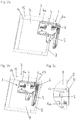
- Figure 4a shows the furniture drive 1 in a perspective view.
- the assembly stop 6 is shown in a pivoted position.
- the mounting plate 7 can be seen, which is suitable for fastening the drive unit 4 to a wall 9 by means of screws or dowels (not shown).
- Figure 4b shows a detailed representation of the Figure 4a .
- the axis of rotation D of the actuating part 5 and the direction R refer to the description of FIG Figure 3b referenced.
- the recess 11 of the drive unit 4 can be seen, in which the assembly stop 6 in its first position according to FIG Figure 3a is at least partially absorbable.
- Figure 5a shows the furniture drive 1 according to Figure 4a with a further position of the assembly stop 6, which in addition to the pivoted position of Figure 4a is still shifted along the bolt 10 to the left.
- Figure 5b shows the circled area of the Figure 5a in a different perspective view. So that the assembly stop 6 is held in a predetermined position in the second position, the assembly stop 6 a flattened area 21. Another flattened area 21 is also formed symmetrically to the axis of symmetry S on the other side. As a result, the assembly stop 6 is also held in a predetermined position in the position shifted to the right along the bolt 10. In the position shifted to the left or to the right, the assembly stop 6 does not fall down under its own weight.
- the information "above” and “below” each refer to the usual mounting position of the furniture drive 1.
- Figure 5c shows the detail area according to Figure 5b in another perspective view.
- the recess 11 can be seen, which is provided for at least partially receiving the assembly stop 6 in its first position.
- Figure 6a shows a sectional view of the assembly stop 6 along the axis of symmetry S of the assembly stop 6.
- the assembly stop 6 is movably supported relative to the drive unit 4 via the bolt 10 and is in the first position in this figure.
- the axis A can be seen, about which the assembly stop 6 is pivotably mounted and can be displaced along this axis A.
- Figure 6b shows the assembly stop 6 in contrast to Figure 6a in a position pivoted about the bolt 10.
- Figure 6c and Figure 6d show the assembly stop 6 in a position displaced along the bolt 10. This position corresponds to the second position of the assembly stop 6. Furthermore, this position corresponds to the assembly state of the furniture drive 1, the drive unit 4 of the furniture drive 1 being positionable in this position both in terms of height and depth on or in the furniture body.
- Figure 5b The illustrated flattened area 21 of the assembly stop 6 in the second position on the drive unit 4 at least rests in areas and thus a fall of the assembly stop 6 is prevented by its own weight.
Landscapes
- Engineering & Computer Science (AREA)
- Mechanical Engineering (AREA)
- Hinges (AREA)
- Cabinets, Racks, Or The Like Of Rigid Construction (AREA)
- Power-Operated Mechanisms For Wings (AREA)
- Closing And Opening Devices For Wings, And Checks For Wings (AREA)
- Legs For Furniture In General (AREA)
Claims (15)
- Entraînement pour meuble (1) pour le déplacement d'une partie de meuble (2) logée de façon mobile par rapport à un corps de meuble (3), comprenant :- une unité d'entraînement (4) pour montage sur ou dans le corps de meuble (3),- au moins un organe de commande (5) logé de façon mobile visant à déplacer la partie de meuble mobile (2),
caractérisé en ce que sur l'unité d'entraînement (4) est prévue au moins une butée de montage (6) pouvant être appliquée sur le corps de meuble (3), où la butée de montage (6) est prémontée sur l'unité d'entraînement (4), la butée de montage (6) est disposée à l'état prémonté par rapport à l'unité d'entraînement (4) de façon pivotante et / ou coulissante sur cette unité d'entraînement (4). - Entraînement pour meuble selon la revendication 1, dans lequel l'unité d'entraînement (4) présente un boîtier et / ou une plaque de montage (7) et en ce que la butée de montage (6) est réalisée comme un composant distinct du boîtier et / ou de la plaque de montage (7).
- Entraînement pour meuble selon l'une des revendications 1 ou 2, dans lequel la butée de montage (6) pour le positionnement sur ou dans le corps de meuble (3) peut être appliquée sur un côté frontal (8) d'une paroi (9) - de préférence, paroi latérale (9a) - du corps de meuble (3), dans lequel l'unité d'entraînement (4) peut être positionnée, par le placement de la butée de montage (6) sur le côté frontal (8) de la paroi (9), à une position de montage prédéfinie sur ou dans le corps de meuble (3).
- Entraînement pour meuble selon l'une des revendications 1 à 3, dans lequel la butée de montage (6) est coulissante par rapport à l'unité d'entrainement (4) uniquement après un mouvement pivotant au moins partiellement réalisé.
- Entraînement pour meuble selon l'une des revendications 1 à 4, dans lequel la butée de montage (6) est logée de façon mobile et limitée entre une première position et une deuxième position, dans lequel la butée de montage (6) est logée au moins partiellement dans la première position dans un évidement (11) de l'entraînement pour meuble (1) et, dans la deuxième position, dépasse transversalement de l'unité d'entraînement (4) de sorte que la butée de montage (6) peut être appliquée sur un côté frontal (8) du corps de meuble (3).
- Entraînement pour meuble selon la revendication 5, dans lequel la butée de montage (6) présente au moins une surface de butée (12) pour placement sur le côté frontal (8) du corps de meuble (3).
- Entraînement pour meuble selon la revendication 6, dans lequel la butée de montage (6) présente au moins deux surfaces de butée (12, 12a), lesquelles peuvent être appliquées facultativement à deux côtés frontaux différents (8, 8a) de deux parois latérales opposées (9a, 9b) du corps de meuble (3).
- Entraînement pour meuble selon l'une des revendications 1 à 7, dans lequel la butée de montage (6) est conçue essentiellement en forme de T.
- Meuble avec au moins un entraînement pour meuble selon l'une des revendications 1 à 8.
- Meuble selon la revendication 9, dans lequel le meuble (16) présente un corps de meuble (3) et une partie de meuble (2) - de préférence un abattant- mobile en hauteur par rapport au corps de meuble (3), dans lequel la partie de meuble (2) est logée de façon mobile par l'entraînement de meuble (1) entre une position fermée et une position relevée par rapport au corps de meuble (3).
- Procédé de montage d'un entraînement pour meuble, plus particulièrement selon l'une des revendications 1 à 8, sur ou dans un corps de meuble, caractérisé par les étapes suivantes :- déplacement d'une unité d'entraînement (4) dans une position jusqu'à ce qu'une butée de montage (6) bute sur un côté frontal (8) d'une paroi (9) - de préférence paroi latérale (9a) - du corps de meuble (3), de sorte que l'unité d'entraînement (4) est positionnée en profondeur à une position de montage prédéfinie sur ou dans le corps de meuble (3),- fixation de l'unité d'entraînement (4) à la position de montage prédéfinie sur ou dans le corps de meuble (3), de préférence au moyen de vis ou de chevilles.
- Procédé selon la revendication 11, caractérisé par l'étape suivante avant le déplacement de l'unité d'entraînement (4) :- pivotement et / ou déplacement de la butée de montage (6) par rapport à l'unité d'entraînement (4) dans une deuxième position, dans laquelle la butée de montage (6) dépasse transversalement de l'unité d'entraînement (4), de sorte que la butée de montage (6) peut être appliquée à un côté frontal (8) du corps de meuble (3).
- Procédé selon la revendication 11 ou 12, caractérisé par l'étape suivante avant ou après la fixation de l'unité d'entraînement (4) :- pivotement et / ou déplacement de la butée de montage (6) par rapport à l'unité d'entraînement (4) dans une première position, dans laquelle la butée de montage (6) est logée au moins partiellement dans un évidement (11) de l'entraînement de meuble (1).
- Procédé selon l'une des revendications 11 à 13, caractérisé par l'étape suivante avant la fixation de l'unité d'entraînement (4) :- déplacement de l'unité d'entraînement (4) dans une position jusqu'à ce qu'une butée (6a), séparée de préférence de la butée de montage (6), de l'unité d'entraînement (4) bute sur un côté inférieur (14) d'une paroi de plafond (15) du corps de meuble (3), de sorte que l'unité d'entraînement (4) est positionnée en hauteur à une position de montage prédéfinie (3) sur ou dans le corps de meuble.
- Procédé selon l'une des revendications 11 à 14, dans lequel l'unité d'entraînement (4), pendant le déplacement menant au positionnement, est adjacente à une paroi (9) - de préférence paroi latérale (9a) - du corps de meuble (3) et est déplacée le long de cette paroi (9).
Priority Applications (1)
| Application Number | Priority Date | Filing Date | Title |
|---|---|---|---|
| EP20203361.9A EP3786405B1 (fr) | 2017-01-31 | 2018-01-18 | Entraînement de meuble permettant de déplacer un élément de meuble monté mobile |
Applications Claiming Priority (2)
| Application Number | Priority Date | Filing Date | Title |
|---|---|---|---|
| ATA50068/2017A AT519632B1 (de) | 2017-01-31 | 2017-01-31 | Möbelantrieb zum Bewegen eines bewegbar gelagerten Möbelteiles |
| PCT/AT2018/060015 WO2018140991A1 (fr) | 2017-01-31 | 2018-01-18 | Mécanisme d'entrainement pour meuble servant à déplacer une partie de meuble montée mobile |
Related Child Applications (1)
| Application Number | Title | Priority Date | Filing Date |
|---|---|---|---|
| EP20203361.9A Division EP3786405B1 (fr) | 2017-01-31 | 2018-01-18 | Entraînement de meuble permettant de déplacer un élément de meuble monté mobile |
Publications (2)
| Publication Number | Publication Date |
|---|---|
| EP3577295A1 EP3577295A1 (fr) | 2019-12-11 |
| EP3577295B1 true EP3577295B1 (fr) | 2020-10-28 |
Family
ID=61282925
Family Applications (2)
| Application Number | Title | Priority Date | Filing Date |
|---|---|---|---|
| EP18707221.0A Active EP3577295B1 (fr) | 2017-01-31 | 2018-01-18 | Mécanisme d'entrainement pour meuble servant à déplacer une partie de meuble montée mobile |
| EP20203361.9A Active EP3786405B1 (fr) | 2017-01-31 | 2018-01-18 | Entraînement de meuble permettant de déplacer un élément de meuble monté mobile |
Family Applications After (1)
| Application Number | Title | Priority Date | Filing Date |
|---|---|---|---|
| EP20203361.9A Active EP3786405B1 (fr) | 2017-01-31 | 2018-01-18 | Entraînement de meuble permettant de déplacer un élément de meuble monté mobile |
Country Status (9)
| Country | Link |
|---|---|
| US (1) | US11136805B2 (fr) |
| EP (2) | EP3577295B1 (fr) |
| JP (1) | JP6805357B2 (fr) |
| CN (1) | CN110234829B (fr) |
| AT (1) | AT519632B1 (fr) |
| ES (2) | ES2964825T3 (fr) |
| HU (2) | HUE053091T2 (fr) |
| TW (1) | TWI660697B (fr) |
| WO (1) | WO2018140991A1 (fr) |
Families Citing this family (2)
| Publication number | Priority date | Publication date | Assignee | Title |
|---|---|---|---|---|
| AT524338B1 (de) * | 2020-10-22 | 2023-08-15 | Blum Gmbh Julius | Möbelantrieb |
| AT526131A1 (de) * | 2022-05-05 | 2023-11-15 | Blum Gmbh Julius | Verfahren zur montage eines möbelantriebs |
Family Cites Families (20)
| Publication number | Priority date | Publication date | Assignee | Title |
|---|---|---|---|---|
| AT376770B (de) * | 1978-07-28 | 1984-12-27 | Heinze Richard Gmbh Co Kg | Moebelbeschlagteil |
| AT391344B (de) * | 1987-08-31 | 1990-09-25 | Blum Gmbh Julius | Scharnier |
| AT405553B (de) * | 1994-09-06 | 1999-09-27 | Blum Gmbh Julius | Rahmenscharnier |
| DE29518683U1 (de) * | 1995-11-25 | 1997-03-20 | Mepla-Werke Lautenschläger GmbH & Co KG, 64354 Reinheim | Vorrichtung zur Montage von an einem Türflügel vormontierten Scharnieren an einem Schrankkorpus |
| EP0851084B1 (fr) * | 1996-12-30 | 1999-10-06 | Electrolux AG | Ferrure de charnière, structure en forme de caisson avec une telle ferrure et sa méthode de montage |
| CN1985064B (zh) * | 2004-07-14 | 2011-08-24 | 尤利乌斯·布卢姆有限公司 | 可旋转支承的操纵臂的操纵机构 |
| AT502938A1 (de) * | 2004-11-18 | 2007-06-15 | Blum Gmbh Julius | Stellantrieb zum bewegen einer klappe eines möbels |
| ITRM20060162U1 (it) * | 2006-09-12 | 2008-03-13 | Salice Arturo Spa | Dispositivo di chiusura e apertura del tipo a scatto di una parte movibile di un mobile |
| ITMO20080003A1 (it) * | 2008-01-08 | 2009-07-09 | Baldacci S P A | Dispositivo di incernieramento di ante per mobili per l'arredamento di veicoli, particolarmente caravan, autocaravan e veicoli nautici |
| AT507041A1 (de) * | 2008-06-19 | 2010-01-15 | Blum Gmbh Julius | Möbelantrieb |
| AT507139A1 (de) * | 2008-07-18 | 2010-02-15 | Blum Gmbh Julius | Möbelantrieb |
| JP5415490B2 (ja) * | 2011-07-29 | 2014-02-12 | スガツネ工業株式会社 | 支持部材付き扉開閉装置及び扉開閉装置用の支持部材 |
| JP5415491B2 (ja) | 2011-07-29 | 2014-02-12 | スガツネ工業株式会社 | 扉開閉装置ユニット及び扉開閉装置ユニットの取付け方法 |
| JP5980491B2 (ja) * | 2011-10-21 | 2016-08-31 | 株式会社太田製作所 | スライド蝶番及びスライド蝶番を備えた収納体 |
| AT513033B1 (de) * | 2012-08-27 | 2014-01-15 | Blum Gmbh Julius | Montageplatte für Möbelstellantriebe |
| EP2894370B1 (fr) * | 2012-09-10 | 2019-11-20 | Fukoku Co., Ltd. | Support rempli de liquide |
| TWI476318B (zh) * | 2012-12-07 | 2015-03-11 | King Slide Works Co Ltd | 緩衝鉸鍊 |
| AT515216B1 (de) * | 2014-05-02 | 2015-07-15 | Blum Gmbh Julius | Stellantrieb für Möbelklappen |
| US9664215B2 (en) * | 2014-11-20 | 2017-05-30 | Hardware Resources, Inc. | Removable compact hinge and method of use |
| BR112017021309A2 (pt) * | 2015-04-30 | 2018-06-26 | Salice Arturo Spa | dobradiça para folhas de mobiliário que oscilam em torno de pelo menos um eixo horizontal |
-
2017
- 2017-01-31 AT ATA50068/2017A patent/AT519632B1/de active
-
2018
- 2018-01-18 EP EP18707221.0A patent/EP3577295B1/fr active Active
- 2018-01-18 ES ES20203361T patent/ES2964825T3/es active Active
- 2018-01-18 JP JP2019541328A patent/JP6805357B2/ja active Active
- 2018-01-18 CN CN201880009359.1A patent/CN110234829B/zh active Active
- 2018-01-18 ES ES18707221T patent/ES2844191T3/es active Active
- 2018-01-18 HU HUE18707221A patent/HUE053091T2/hu unknown
- 2018-01-18 WO PCT/AT2018/060015 patent/WO2018140991A1/fr not_active Ceased
- 2018-01-18 EP EP20203361.9A patent/EP3786405B1/fr active Active
- 2018-01-18 HU HUE20203361A patent/HUE063683T2/hu unknown
- 2018-01-23 TW TW107102309A patent/TWI660697B/zh active
-
2019
- 2019-07-30 US US16/526,282 patent/US11136805B2/en active Active
Non-Patent Citations (1)
| Title |
|---|
| None * |
Also Published As
| Publication number | Publication date |
|---|---|
| WO2018140991A1 (fr) | 2018-08-09 |
| HUE053091T2 (hu) | 2021-06-28 |
| HUE063683T2 (hu) | 2024-01-28 |
| AT519632A1 (de) | 2018-08-15 |
| AT519632B1 (de) | 2019-03-15 |
| US11136805B2 (en) | 2021-10-05 |
| CN110234829B (zh) | 2021-01-01 |
| ES2964825T3 (es) | 2024-04-09 |
| EP3786405A1 (fr) | 2021-03-03 |
| TWI660697B (zh) | 2019-06-01 |
| EP3577295A1 (fr) | 2019-12-11 |
| JP6805357B2 (ja) | 2020-12-23 |
| US20190352952A1 (en) | 2019-11-21 |
| TW201831119A (zh) | 2018-09-01 |
| JP2020514592A (ja) | 2020-05-21 |
| EP3786405B1 (fr) | 2023-08-09 |
| ES2844191T3 (es) | 2021-07-21 |
| CN110234829A (zh) | 2019-09-13 |
Similar Documents
| Publication | Publication Date | Title |
|---|---|---|
| DE69705662T2 (de) | Rollvorrichtung für Schiebetüren, Fenster oder ähnliches | |
| EP3556978B1 (fr) | Dispositif de déplacement d'une partie de meuble logée sur une partie d'un meuble | |
| EP2715021B1 (fr) | Scharnière | |
| AT519903B1 (de) | Schiene zur Führung eines Schlittens einer Möbeltüre | |
| WO2018204956A1 (fr) | Commande de meuble à moteur | |
| DE102008032750A1 (de) | Beschlag für kraftbetätigte Parallelausstellfenster | |
| EP3486420A2 (fr) | Procédé de positionnement d'une fenêtre ou d'une porte | |
| EP3577295B1 (fr) | Mécanisme d'entrainement pour meuble servant à déplacer une partie de meuble montée mobile | |
| EP2792830B1 (fr) | Partie de ferrure avec élément de maintien | |
| WO2002022996A1 (fr) | Systeme d'ouverture de porte destine notamment a des vehicules | |
| DE112014006955B4 (de) | Türscharnier mit höhenverstellvorrichtung für eine drehende tür | |
| EP1673249B1 (fr) | Element de blocage de portiere | |
| DE202016106504U1 (de) | Montagewerkzeug für die Montage einer Schaltschranktür an einem Schaltschrankgehäuse und eine entsprechende Schaltschrankanordnung | |
| EP3695748A1 (fr) | Dispositif formant une armoire encastrée | |
| EP3327228B1 (fr) | Dispositif de verrouillage destiné à verrouiller et à emmener au moins deux éléments en forme de plaque montés en coulissement le long d'une première direction de coulissement et d'une seconde direction de coulissement opposée et système de paroi comprenant au moins deux éléments en forme de plaque | |
| DE102007040281B3 (de) | Vorrichtung zum Ablängen von Fensterbeschlagteilen | |
| DE102017220895B4 (de) | Lehrenanordnung zur Montage eines Steuerelements eines Schiebefensters oder einer Schiebetür | |
| DE102016004915B3 (de) | Beschlag für ein Fenster, Verfahren zum Herstellen des Beschlags sowie entsprechendes Fenster | |
| EP3947236A1 (fr) | Système d'entraînement variable | |
| DE102012222210A1 (de) | Zur verdeckten Anordnung vorgesehenes Ecklager | |
| EP2685040A2 (fr) | Composant précontraint et procédé de fonctionnement pour une fenêtre ou une porte-fenêtre | |
| EP3095937A1 (fr) | Raccordement de vantail de porte mobile | |
| DE19963555B4 (de) | Armfensterheber | |
| DE102014017389B4 (de) | Verfahren zum Einstellen der Lage eines Karosseriebauteils an einer Fahrzeugkarosserie | |
| DE102023102477A1 (de) | Aufstellen von Fahrzeugtüren |
Legal Events
| Date | Code | Title | Description |
|---|---|---|---|
| STAA | Information on the status of an ep patent application or granted ep patent |
Free format text: STATUS: UNKNOWN |
|
| STAA | Information on the status of an ep patent application or granted ep patent |
Free format text: STATUS: THE INTERNATIONAL PUBLICATION HAS BEEN MADE |
|
| PUAI | Public reference made under article 153(3) epc to a published international application that has entered the european phase |
Free format text: ORIGINAL CODE: 0009012 |
|
| STAA | Information on the status of an ep patent application or granted ep patent |
Free format text: STATUS: REQUEST FOR EXAMINATION WAS MADE |
|
| 17P | Request for examination filed |
Effective date: 20190823 |
|
| AK | Designated contracting states |
Kind code of ref document: A1 Designated state(s): AL AT BE BG CH CY CZ DE DK EE ES FI FR GB GR HR HU IE IS IT LI LT LU LV MC MK MT NL NO PL PT RO RS SE SI SK SM TR |
|
| AX | Request for extension of the european patent |
Extension state: BA ME |
|
| DAV | Request for validation of the european patent (deleted) | ||
| DAX | Request for extension of the european patent (deleted) | ||
| GRAP | Despatch of communication of intention to grant a patent |
Free format text: ORIGINAL CODE: EPIDOSNIGR1 |
|
| STAA | Information on the status of an ep patent application or granted ep patent |
Free format text: STATUS: GRANT OF PATENT IS INTENDED |
|
| INTG | Intention to grant announced |
Effective date: 20200713 |
|
| GRAS | Grant fee paid |
Free format text: ORIGINAL CODE: EPIDOSNIGR3 |
|
| GRAA | (expected) grant |
Free format text: ORIGINAL CODE: 0009210 |
|
| STAA | Information on the status of an ep patent application or granted ep patent |
Free format text: STATUS: THE PATENT HAS BEEN GRANTED |
|
| AK | Designated contracting states |
Kind code of ref document: B1 Designated state(s): AL AT BE BG CH CY CZ DE DK EE ES FI FR GB GR HR HU IE IS IT LI LT LU LV MC MK MT NL NO PL PT RO RS SE SI SK SM TR |
|
| REG | Reference to a national code |
Ref country code: GB Ref legal event code: FG4D Free format text: NOT ENGLISH |
|
| REG | Reference to a national code |
Ref country code: CH Ref legal event code: EP |
|
| REG | Reference to a national code |
Ref country code: AT Ref legal event code: REF Ref document number: 1328404 Country of ref document: AT Kind code of ref document: T Effective date: 20201115 |
|
| REG | Reference to a national code |
Ref country code: DE Ref legal event code: R096 Ref document number: 502018002858 Country of ref document: DE |
|
| REG | Reference to a national code |
Ref country code: IE Ref legal event code: FG4D Free format text: LANGUAGE OF EP DOCUMENT: GERMAN |
|
| REG | Reference to a national code |
Ref country code: NL Ref legal event code: MP Effective date: 20201028 |
|
| PG25 | Lapsed in a contracting state [announced via postgrant information from national office to epo] |
Ref country code: FI Free format text: LAPSE BECAUSE OF FAILURE TO SUBMIT A TRANSLATION OF THE DESCRIPTION OR TO PAY THE FEE WITHIN THE PRESCRIBED TIME-LIMIT Effective date: 20201028 Ref country code: PT Free format text: LAPSE BECAUSE OF FAILURE TO SUBMIT A TRANSLATION OF THE DESCRIPTION OR TO PAY THE FEE WITHIN THE PRESCRIBED TIME-LIMIT Effective date: 20210301 Ref country code: RS Free format text: LAPSE BECAUSE OF FAILURE TO SUBMIT A TRANSLATION OF THE DESCRIPTION OR TO PAY THE FEE WITHIN THE PRESCRIBED TIME-LIMIT Effective date: 20201028 Ref country code: GR Free format text: LAPSE BECAUSE OF FAILURE TO SUBMIT A TRANSLATION OF THE DESCRIPTION OR TO PAY THE FEE WITHIN THE PRESCRIBED TIME-LIMIT Effective date: 20210129 Ref country code: NO Free format text: LAPSE BECAUSE OF FAILURE TO SUBMIT A TRANSLATION OF THE DESCRIPTION OR TO PAY THE FEE WITHIN THE PRESCRIBED TIME-LIMIT Effective date: 20210128 |
|
| REG | Reference to a national code |
Ref country code: LT Ref legal event code: MG4D |
|
| PG25 | Lapsed in a contracting state [announced via postgrant information from national office to epo] |
Ref country code: PL Free format text: LAPSE BECAUSE OF FAILURE TO SUBMIT A TRANSLATION OF THE DESCRIPTION OR TO PAY THE FEE WITHIN THE PRESCRIBED TIME-LIMIT Effective date: 20201028 Ref country code: IS Free format text: LAPSE BECAUSE OF FAILURE TO SUBMIT A TRANSLATION OF THE DESCRIPTION OR TO PAY THE FEE WITHIN THE PRESCRIBED TIME-LIMIT Effective date: 20210228 Ref country code: LV Free format text: LAPSE BECAUSE OF FAILURE TO SUBMIT A TRANSLATION OF THE DESCRIPTION OR TO PAY THE FEE WITHIN THE PRESCRIBED TIME-LIMIT Effective date: 20201028 Ref country code: SE Free format text: LAPSE BECAUSE OF FAILURE TO SUBMIT A TRANSLATION OF THE DESCRIPTION OR TO PAY THE FEE WITHIN THE PRESCRIBED TIME-LIMIT Effective date: 20201028 Ref country code: BG Free format text: LAPSE BECAUSE OF FAILURE TO SUBMIT A TRANSLATION OF THE DESCRIPTION OR TO PAY THE FEE WITHIN THE PRESCRIBED TIME-LIMIT Effective date: 20210128 |
|
| REG | Reference to a national code |
Ref country code: HU Ref legal event code: AG4A Ref document number: E053091 Country of ref document: HU |
|
| PG25 | Lapsed in a contracting state [announced via postgrant information from national office to epo] |
Ref country code: NL Free format text: LAPSE BECAUSE OF FAILURE TO SUBMIT A TRANSLATION OF THE DESCRIPTION OR TO PAY THE FEE WITHIN THE PRESCRIBED TIME-LIMIT Effective date: 20201028 Ref country code: HR Free format text: LAPSE BECAUSE OF FAILURE TO SUBMIT A TRANSLATION OF THE DESCRIPTION OR TO PAY THE FEE WITHIN THE PRESCRIBED TIME-LIMIT Effective date: 20201028 |
|
| REG | Reference to a national code |
Ref country code: ES Ref legal event code: FG2A Ref document number: 2844191 Country of ref document: ES Kind code of ref document: T3 Effective date: 20210721 |
|
| REG | Reference to a national code |
Ref country code: DE Ref legal event code: R097 Ref document number: 502018002858 Country of ref document: DE |
|
| PG25 | Lapsed in a contracting state [announced via postgrant information from national office to epo] |
Ref country code: LT Free format text: LAPSE BECAUSE OF FAILURE TO SUBMIT A TRANSLATION OF THE DESCRIPTION OR TO PAY THE FEE WITHIN THE PRESCRIBED TIME-LIMIT Effective date: 20201028 Ref country code: RO Free format text: LAPSE BECAUSE OF FAILURE TO SUBMIT A TRANSLATION OF THE DESCRIPTION OR TO PAY THE FEE WITHIN THE PRESCRIBED TIME-LIMIT Effective date: 20201028 Ref country code: EE Free format text: LAPSE BECAUSE OF FAILURE TO SUBMIT A TRANSLATION OF THE DESCRIPTION OR TO PAY THE FEE WITHIN THE PRESCRIBED TIME-LIMIT Effective date: 20201028 Ref country code: CZ Free format text: LAPSE BECAUSE OF FAILURE TO SUBMIT A TRANSLATION OF THE DESCRIPTION OR TO PAY THE FEE WITHIN THE PRESCRIBED TIME-LIMIT Effective date: 20201028 Ref country code: SM Free format text: LAPSE BECAUSE OF FAILURE TO SUBMIT A TRANSLATION OF THE DESCRIPTION OR TO PAY THE FEE WITHIN THE PRESCRIBED TIME-LIMIT Effective date: 20201028 Ref country code: SK Free format text: LAPSE BECAUSE OF FAILURE TO SUBMIT A TRANSLATION OF THE DESCRIPTION OR TO PAY THE FEE WITHIN THE PRESCRIBED TIME-LIMIT Effective date: 20201028 |
|
| PG25 | Lapsed in a contracting state [announced via postgrant information from national office to epo] |
Ref country code: MC Free format text: LAPSE BECAUSE OF FAILURE TO SUBMIT A TRANSLATION OF THE DESCRIPTION OR TO PAY THE FEE WITHIN THE PRESCRIBED TIME-LIMIT Effective date: 20201028 Ref country code: DK Free format text: LAPSE BECAUSE OF FAILURE TO SUBMIT A TRANSLATION OF THE DESCRIPTION OR TO PAY THE FEE WITHIN THE PRESCRIBED TIME-LIMIT Effective date: 20201028 |
|
| REG | Reference to a national code |
Ref country code: CH Ref legal event code: PL |
|
| PLBE | No opposition filed within time limit |
Free format text: ORIGINAL CODE: 0009261 |
|
| STAA | Information on the status of an ep patent application or granted ep patent |
Free format text: STATUS: NO OPPOSITION FILED WITHIN TIME LIMIT |
|
| PG25 | Lapsed in a contracting state [announced via postgrant information from national office to epo] |
Ref country code: LU Free format text: LAPSE BECAUSE OF NON-PAYMENT OF DUE FEES Effective date: 20210118 |
|
| 26N | No opposition filed |
Effective date: 20210729 |
|
| REG | Reference to a national code |
Ref country code: BE Ref legal event code: MM Effective date: 20210131 |
|
| PG25 | Lapsed in a contracting state [announced via postgrant information from national office to epo] |
Ref country code: AL Free format text: LAPSE BECAUSE OF FAILURE TO SUBMIT A TRANSLATION OF THE DESCRIPTION OR TO PAY THE FEE WITHIN THE PRESCRIBED TIME-LIMIT Effective date: 20201028 Ref country code: FR Free format text: LAPSE BECAUSE OF NON-PAYMENT OF DUE FEES Effective date: 20210131 |
|
| PG25 | Lapsed in a contracting state [announced via postgrant information from national office to epo] |
Ref country code: LI Free format text: LAPSE BECAUSE OF NON-PAYMENT OF DUE FEES Effective date: 20210131 Ref country code: CH Free format text: LAPSE BECAUSE OF NON-PAYMENT OF DUE FEES Effective date: 20210131 Ref country code: SI Free format text: LAPSE BECAUSE OF FAILURE TO SUBMIT A TRANSLATION OF THE DESCRIPTION OR TO PAY THE FEE WITHIN THE PRESCRIBED TIME-LIMIT Effective date: 20201028 |
|
| PG25 | Lapsed in a contracting state [announced via postgrant information from national office to epo] |
Ref country code: IE Free format text: LAPSE BECAUSE OF NON-PAYMENT OF DUE FEES Effective date: 20210118 |
|
| PG25 | Lapsed in a contracting state [announced via postgrant information from national office to epo] |
Ref country code: IS Free format text: LAPSE BECAUSE OF FAILURE TO SUBMIT A TRANSLATION OF THE DESCRIPTION OR TO PAY THE FEE WITHIN THE PRESCRIBED TIME-LIMIT Effective date: 20210228 |
|
| PG25 | Lapsed in a contracting state [announced via postgrant information from national office to epo] |
Ref country code: BE Free format text: LAPSE BECAUSE OF NON-PAYMENT OF DUE FEES Effective date: 20210131 |
|
| GBPC | Gb: european patent ceased through non-payment of renewal fee |
Effective date: 20220118 |
|
| PG25 | Lapsed in a contracting state [announced via postgrant information from national office to epo] |
Ref country code: GB Free format text: LAPSE BECAUSE OF NON-PAYMENT OF DUE FEES Effective date: 20220118 |
|
| P01 | Opt-out of the competence of the unified patent court (upc) registered |
Effective date: 20230523 |
|
| PG25 | Lapsed in a contracting state [announced via postgrant information from national office to epo] |
Ref country code: CY Free format text: LAPSE BECAUSE OF FAILURE TO SUBMIT A TRANSLATION OF THE DESCRIPTION OR TO PAY THE FEE WITHIN THE PRESCRIBED TIME-LIMIT Effective date: 20201028 |
|
| PG25 | Lapsed in a contracting state [announced via postgrant information from national office to epo] |
Ref country code: MK Free format text: LAPSE BECAUSE OF FAILURE TO SUBMIT A TRANSLATION OF THE DESCRIPTION OR TO PAY THE FEE WITHIN THE PRESCRIBED TIME-LIMIT Effective date: 20201028 |
|
| PG25 | Lapsed in a contracting state [announced via postgrant information from national office to epo] |
Ref country code: MT Free format text: LAPSE BECAUSE OF FAILURE TO SUBMIT A TRANSLATION OF THE DESCRIPTION OR TO PAY THE FEE WITHIN THE PRESCRIBED TIME-LIMIT Effective date: 20201028 |
|
| PGFP | Annual fee paid to national office [announced via postgrant information from national office to epo] |
Ref country code: HU Payment date: 20260115 Year of fee payment: 9 |
|
| PGFP | Annual fee paid to national office [announced via postgrant information from national office to epo] |
Ref country code: ES Payment date: 20260210 Year of fee payment: 9 |
|
| PGFP | Annual fee paid to national office [announced via postgrant information from national office to epo] |
Ref country code: DE Payment date: 20260127 Year of fee payment: 9 |
|
| PGFP | Annual fee paid to national office [announced via postgrant information from national office to epo] |
Ref country code: AT Payment date: 20260127 Year of fee payment: 9 |
|
| PGFP | Annual fee paid to national office [announced via postgrant information from national office to epo] |
Ref country code: IT Payment date: 20260123 Year of fee payment: 9 |
|
| PGFP | Annual fee paid to national office [announced via postgrant information from national office to epo] |
Ref country code: TR Payment date: 20260107 Year of fee payment: 9 |