EP3096053A1 - Vanne electromagnetique cryogenique autoclave pour lanceur spatial - Google Patents
Vanne electromagnetique cryogenique autoclave pour lanceur spatial Download PDFInfo
- Publication number
- EP3096053A1 EP3096053A1 EP16169668.7A EP16169668A EP3096053A1 EP 3096053 A1 EP3096053 A1 EP 3096053A1 EP 16169668 A EP16169668 A EP 16169668A EP 3096053 A1 EP3096053 A1 EP 3096053A1
- Authority
- EP
- European Patent Office
- Prior art keywords
- plunger
- seat
- electromagnetic valve
- shutters
- shutter
- Prior art date
- Legal status (The legal status is an assumption and is not a legal conclusion. Google has not performed a legal analysis and makes no representation as to the accuracy of the status listed.)
- Granted
Links
Images



Classifications
-
- F—MECHANICAL ENGINEERING; LIGHTING; HEATING; WEAPONS; BLASTING
- F16—ENGINEERING ELEMENTS AND UNITS; GENERAL MEASURES FOR PRODUCING AND MAINTAINING EFFECTIVE FUNCTIONING OF MACHINES OR INSTALLATIONS; THERMAL INSULATION IN GENERAL
- F16K—VALVES; TAPS; COCKS; ACTUATING-FLOATS; DEVICES FOR VENTING OR AERATING
- F16K31/00—Actuating devices; Operating means; Releasing devices
- F16K31/02—Actuating devices; Operating means; Releasing devices electric; magnetic
- F16K31/06—Actuating devices; Operating means; Releasing devices electric; magnetic using a magnet, e.g. diaphragm valves, cutting off by means of a liquid
- F16K31/0603—Multiple-way valves
- F16K31/062—Multiple-way valves the valve element being at least partially ball-shaped
-
- F—MECHANICAL ENGINEERING; LIGHTING; HEATING; WEAPONS; BLASTING
- F16—ENGINEERING ELEMENTS AND UNITS; GENERAL MEASURES FOR PRODUCING AND MAINTAINING EFFECTIVE FUNCTIONING OF MACHINES OR INSTALLATIONS; THERMAL INSULATION IN GENERAL
- F16K—VALVES; TAPS; COCKS; ACTUATING-FLOATS; DEVICES FOR VENTING OR AERATING
- F16K31/00—Actuating devices; Operating means; Releasing devices
- F16K31/02—Actuating devices; Operating means; Releasing devices electric; magnetic
- F16K31/06—Actuating devices; Operating means; Releasing devices electric; magnetic using a magnet, e.g. diaphragm valves, cutting off by means of a liquid
- F16K31/0603—Multiple-way valves
- F16K31/0624—Lift valves
- F16K31/0634—Lift valves with fixed seats positioned between movable valve members
- F16K31/0637—Lift valves with fixed seats positioned between movable valve members with ball shaped valve members
Definitions
- the invention relates to the field of electromagnetic valves. More precisely, the invention deals with an electromagnetic ball valve for supplying cryogenic fluid, such as propellant, from a space aircraft. The invention also proposes a distribution valve controlled by an electromagnetic valve.
- a rocket is propelled with fuel and oxidizer.
- the fuel is usually propellant that is contained in tanks and then distributed under cryogenic conditions.
- solenoid valves are associated with the tanks. They generally have electromagnetic actuators using the current of the electrical network of the rocket; the actuators must adapt to the intensity available on the network.
- the fuel is propellant circulating in gaseous form and at a temperature of up to -200 ° C., and a pressure of the order of 400 bars. This pressure exerts destructive forces on the sealing elements, just like the mechanical vibrations of a rocket during its takeoff. These vibrations can result in accelerations of 60g which precipitates the wear of the sealing surfaces, in concert with the shocks of the movements of closures.
- the document FR 2 487 942 A1 discloses a valve with a distribution level and a level control level of distribution.
- Level distribution comprises two balls cooperating with two opposite seats. An axis disposed between these balls allows them to be opened and closed selectively, a bellows piston can actuate one of these balls.
- the piston is controlled by the pilot level which comprises two balls also connected by an axis and held in closed position by a spring.
- An electromagnetic actuator with a push plunger pushes one of the balls, which itself pushes the other ball through the axis.
- the object of the invention is to solve at least one of the problems posed by the prior art. More specifically, the invention aims to increase the life of an electromagnetic ball valve. The invention also aims to improve the compactness of an electromagnetic valve.
- the invention relates to an electromagnetic valve, particularly for cryogenic fluid, the valve comprising: two seats facing away from each other and / or each facing away from the other seat; a passage connecting the seats; two shutters that cooperate each with one of the seats so that it can be closed and opened; a movable pusher in contact with the shutters so as to transmit the movements of openings and closures from one shutter to the other; a magnetic circuit for conveying a magnetic flux for example from a magnetic source; remarkable in that the pusher comprises a magnetic material and defines a variable gap in the magnetic circuit so that it can be driven by the magnetic flux to move the shutters relative to their respective seat.
- the pusher is disposed between the shutters and possibly between the seats.
- the invention also relates to an electromagnetic valve, particularly for cryogenic fluid, the valve comprising: two seats each facing away from the other seat; two shutters which each cooperate with one of the seats so as to close and open said seat; a passage connecting the seats; a magnetic circuit with a magnetic plunger adapted to be driven by a magnetic field source, the plunger moving the shutters relative to their respective seats; remarkable in that the plunger is placed between the shutters so that each shutter closes its seat by moving the plunger away from said seat.
- the valve comprises pushers cooperating with the shutters, each push rod possibly being able to move one of the shutters through the associated seat.
- At least one or each pusher is movably mounted relative to the plunger so as to be retractable in the plunger, the plunger preferably comprising at least one or two springs configured to deploy the plungers out of the plunger.
- At least one or each pusher comprises a portion of lesser thickness cooperating with one of the shutters.
- the plunger comprises a through channel configured to connect the seats of the passage.
- the valve comprises at least one pusher guide, preferably two pusher guide disposed on either side of the plunger.
- At least one or each seat is formed on a push guide, at least one or each push guide is made of non-magnetic material.
- the valve comprises at least one or two shutter-holders, each shutter-holder being configured to center its shutter with respect to the associated seat during the movements of openings and closures of the shutters.
- the valve comprises a magnetic field source, in particular a coil, one of the seats being disposed inside the magnetic source, the passage possibly passing through said magnetic source.
- the valve comprises a plunger spring holding the plunger in a closed configuration where one of the two shutters, called the inlet shutter, is closed; and where the other of the two shutters, said exhaust shutter, is open.
- the valve comprises at least one shutter spring, preferably two springs for shutters configured to hold each associated shutter in a closed position against the associated seat.
- the passage comprises a side with an inlet and an outlet
- the plunger comprises a face configured to allow communication between the inlet and the outlet when the plunger is pressed against or against the inlet-outlet side .
- the passage comprises an opening, in particular a third opening, which is spaced from the seats connected by the passage.
- At least one or each shutter is a ball, preferably of diameter less than 4.00 mm, more preferably less than 2.00 mm.
- the passage is a pilot passage
- the valve further comprises a fluid distribution level in communication with the pilot passage, the distribution level comprising a dispensing passage, a dispensing inlet with a seat, a dispensing outlet with a seat, two valves selectively opening and closing the dispensing inlet seat and the dispensing outlet seat.
- the distribution valves are controlled by a distribution piston in communication with the piloting passage.
- the face of the plunger comprises a clearance configured to allow communication between the inlet and the outlet when the plunger is pressed against or against the inlet-outlet side.
- the plunger is placed between the shutters so that each shutter opens its seat by bringing the plunger closer to said seat.
- the seats are fixed.
- the valve is a three-way valve.
- each shutter is able to close the circulation via the passage
- the plunger in each position the plunger remains in contact with the shutters.
- the space between the shutters is constant, or the space between the shutters is greater in the closed position than in the open position.
- the opening or the third opening is a feed path.
- At least one or each pusher is made of non-magnetic material.
- At least one or each shutter is made of non-magnetic material.
- the stroke of the plunger and / or each pusher relative to the seats is less than 5.00 mm, preferably less than 2.00 mm, more preferably less than 1.00 mm, possibly less than at 0.50 mm or 0.20 mm.
- the distribution piston is connected to the pilot passage via the user seat of the pilot passage.
- the inlet of the pilot passage communicates with the dispensing inlet independently of the opening or closing of the valve.
- each object of the invention is also applicable to the other objects of the invention.
- each object of the invention is combinable with other objects.
- the present valve has a more durable operation.
- the level of control retains its seal despite the repetition of actuations. Sealing surfaces are exposed to less effort when opening or closing.
- the invention also proposes a solution that decouples the plunger from the shutters, which makes it possible to exploit the inertia of the plunger without creating a direct impact on the shutters. These benefits are maintained despite short response times and high autoclave pressure, for example up to 400 bar.
- inner or inner and outer or outer refer to a positioning relative to the displacement axis of the plunger.
- the axial direction corresponds to the direction along the displacement axis of the plunger.
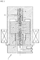
- the figure 1 represents a valve 2 with electrical actuation, more precisely with electromagnetic and mechanical actuation.
- the valve 2 makes it possible to manage a flow of a pressurized fluid, for example a gaseous fluid.
- the valve 2 is here represented in a closed state, a state that it presents in the absence of an electrical supply. However, the valve could be configured to remain open at rest, and close when energized.
- the valve 2 comprises a distribution level 4 allowing the distribution of the fluid, and a control level 6, or control level 6, controlling the distribution level 4.
- the valve 2 may comprise a main body 8; possibly common to both levels, or alternatively made in two parts.
- the driving level 6 may comprise a ferromagnetic carcass 9 making it possible to form a magnetic circuit in the driving level 6.
- the carcass can form a block of material with an internal chamber.
- the valve has a common inlet 10 at the distribution level 4 and at the piloting level 6.
- the dispensing level 4 comprises a dispensing passage 12 connecting a dispensing inlet 14 with a seat, and a dispensing outlet 16 or user port.
- the dispensing passage 12 includes an exhaust 18, possibly with a seat, the outlet 16 being between the inlet 14 and the exhaust 18.
- the distribution level 4 further comprises distribution valves (20; 22) cooperating with the seats of the distribution level 4 so as to close them.
- the valves (20; 22) are fixed to one another and are held closed by a spring 24.
- the distribution valves (20; 22) are controlled by a delivery piston 26 which is actuated by the pressure of the pressurized fluid of the valve 2.
- the piston 26 can be a piston 26 with a bellows 28, or be a piston inserted in a bore of corresponding diameter.
- the interior of the bellows 28 may be in communication with the neighboring exhaust port 18 by means of an orifice 30.
- the piston 26 is housed in a chamber 32 where the pressure variations translate it; translation that is communicated to the valves (20; 22) via a rod 34.
- the pressure in the chamber 32 of the piston is controlled by the control level 6.
- the piston 26 provides mechanical actuation, pneumatic / hydraulic.
- the control level 6 comprises a control passage 36 connecting a pilot input 38 with a seat, and at least one pilot output 40 or third opening 40.
- the pilot output 40 is in hydraulic communication with the piston 26 of the level of distribution 4 via a conduit 42. In this way, when the pilot level 6 opens; the inlet pressure 10 of the valve 2 is exerted on the piston 26, and moves it.
- the pilot passage 36 may comprise a pilot exhaust 44 with a seat, the pilot output 40 being between the pilot input 38 and the pilot exhaust 44.
- the pilot exhaust 44 accelerates the pressure descent. on the piston 26 when the pilot level 6 is cut.
- the figure 2 represents the valve 2 in the open position.
- the control level is open and allows the pressure of the pressurized fluid to act in and on the distribution level.
- the pilot level is open. It is crossed by the fluid. An equilibrium of the pressures is reached between its inlet 38 and its outlet 40 via its pilot passage 36.
- the conduit 42 communicates this pressure to the piston 26 which shifts the valves (20; 22). These then occupy a open position, where the inlet valve 20 opens its seat while the exhaust valve 22 closes his.
- the distribution input 14 then communicates the distribution output 16, possibly directly. Valve 2 is open.
- the figure 3 represents an enlargement of the driving level 6 in the closed position, at rest, when the valve is not powered electrically.
- the command level is not represented.
- the closed state of the control level 6 can be obtained by closing its input 38 and / or by closing its output 40.
- the pilot input 38 includes an input shutter 46, such as an input ball 46 for closing it.
- the ball 46 may be arranged upstream of the inlet seat so that the pressure of the fluid keeps it closed, which gives it an autoclave character.
- a spring 48 can participate in this closing effect.
- the choice of a ball 46 is advantageous because this element can be produced with strict sphericity tolerances; of the order of a micrometer which limits leaks.
- the ball 46 can be impacted on its seat to deform and that the sealing interface is more adjusted.
- the pilot exhaust 44 may comprise an exhaust shutter 50, such as a ball 50 on the downstream side of the seat to seal it, so that the pressure can contribute to opening the exhaust shutter. It is remarkable that the two seats of the pilot level 6 are turned to the opposite of each other. The seat faces each receiving a shutter are facing away from where the other seat is.
- the shutters (46; 50) are placed in separate chambers, possibly separated by another chamber; in this case the pilot passage 36. In the state shown, the exhaust ball 50 is spaced from its seat so that the two faces of the piston remain at the pressure of the exhaust; a balance of pressures.
- the balls (46; 50) may be made of ceramic material to increase the hardness and limit the inertia.
- the control level 6 comprises magnetic actuation means. It may comprise a coil 52, which possibly surrounds the pilot passage 36, and / or the pilot input seat, and / or the input shutter 46.
- the coil 52 may comprise several units, several solenoids, arranged axially one beside the other, and / or fitted into one another.
- the coil 52 can be arranged between the input 38 and the output 40 of the control level 6.
- the control passage 36 can also be surrounded by the magnetic housing 9 forming the magnetic circuit.
- the passage 36 comprises a face on which the inlet 38 and the outlet 40 open. In this way, they are closer to one another and the pressure losses are limited for faster reactions. However, it is conceivable to place the outlet on the exhaust side with respect to the magnetic means.
- the driving level 6 comprises a magnetic plunger 54 which is disposed inside the coil 52, where it is subjected to the magnetic flux of the magnetic circuit.
- the magnetic plunger is disposed between the shutters (46; 50) so that each seat can be opened by approaching said seat and pushing the corresponding shutter.
- the steering level becomes shorter axially. By moving the plunger away from the seat, the shutter closes said seat closer to it. Each shutter is pushed or pushed towards the diver.
- the plunger 54 may form a movable face of the passage 36.
- the plunger 54 may comprise a ferromagnetic material so as to conduct magnetic flux field lines.
- the plunger 54 is mobile, its movements allow to open and close the pilot level 6. It may have a passage 55 connecting the inlet 38 to the exhaust 44. This passage is optional because the leaks controlled around the plunger 54 may be sufficient to balance the pressures depending on the pressures involved and the desired response time.
- At least one or each shutter (46; 50) may comprise a ball, and optionally a ball holder 56 or shutter door 56.
- Each ball holder 56 may comprise an orifice allowing a flow from one face to the other. However, the presence of this orifice is not essential because leaks, possibly controlled, around the ball holder 56 may be sufficient to achieve the pressure actuating the piston of the distribution level.
- Each ball holder 56 can center its ball (46; 50) and form an intermediate with the associated spring (48; 51).
- the control level 6 may comprise push-buttons 58 driven by the plunger 54. These plunges cooperate with the shutters (46; 50).
- the pushers 58 can push the shutters (46; 50) away from their respective seats to allow opening and circulation of fluid through the passage 36.
- Each pusher 58 can also move away from its shutter (46; 50). associated so that it returns to its seat to ensure a seal.
- the pushers 58 may be mounted movable relative to the plunger 54.
- the plunger 54 may comprise cavities 60 receiving portions of pushers 58, and possibly elastic means such as springs 62.
- the pushers 58 can retract and deploy by relative to the plunger 54.
- the plunger spring 62 pushes in the opposite direction of the resilient shutter means (48; 51). It is possible to create a mechanical chain, possibly continuous, of a shutter (46; 50) to the other. This possibility makes it possible to eliminate the gaps between the push-buttons 58 and the shutters (46; 50), and the contact shocks.
- the elastic means 62 of the pushers 58 to take over the elastic means (48; 51) of the shutters (46; 50).
- the elastic means 62 of pushers 58 may be stiffer than the elastic means (48; 51) of shutters (46; 50). The opposite is possible, for example by acting on the prestressing.
- the displacement of the plunger 54 can be decoupled from the pushers 58 and therefore the shutters (46; 50).
- the plunger 54 may have a stroke longer than the displacement required to open a shutter (46; 50). In this way it becomes possible to modulate, possibly increase, air gaps 64 on both sides of the plunger 54.
- the plunger 54 may comprise abutment surfaces, in particular axial, cooperating with the push-buttons 58.
- the elastic means 62 of the push-buttons 58 may then be less stiff than the resilient means (48; 51) of shutters (46; 50). This arrangement makes it possible to move the mechanical clearances, so that they are not at the level of the shutters, but between the plunger 54 and the push-buttons 58. Thus, the interfaces with the shutters (46; 50) are preserved in time. .
- At least one or each pusher 58 may be made of a non-magnetic material, for example to prevent magnetic short circuits. They may include portions of smaller thickness, such as needles through each seat. A shutter (46; 50) can then be actuated from the face opposite to the seat.
- the seats of the driving level can be formed on inserts 66, possibly made of non-magnetic materials. They may also serve as a push guide 66. At least one or each push guide 66 may comprise a guide surface in which the corresponding pusher 58 slides. A passage may be formed between each or at least one pusher torque 58 - pusher guide 66, for example on the pusher 58. This passage allows a flow of fluid and / or pressure balancing.
- a pilot spring 68 can press the plunger 54 into its closed position. This spring 68 is supported on the face encompassing the inlet and the outlet. It is crossed by the pilot passage 36.
- the pushers 58 are introduced into the plunger 54.
- each pusher interface can be brought closer to the neighboring shutter.
- these interfaces may be inside the push guides.
- the plunger may include litters inserted into and sliding within the guides. These guides can then be guide-divers.
- the figure 4 is a view of the valve in the open position.
- the actuating means 52 are powered. Current flows in the coils 52.
- the magnetic means 52 generate a magnetic flux in the magnetic circuit of the carcass, so that a force tends to close the air gap 64 by moving the plunger 54 to the inlet shutter 46.
- the plunger pushes the inlet shutter 46 out of its seat and opens the control level 6.
- the opening may be partial. It allows a circulation or a balance of the pressures allowing to actuate the level of distribution and to open it as represented in figure 2 .
- the different embodiments presented above can be combined. Different arrangement between the inlet, the outlet, the exhaust are envisaged.
- the inlet and outlet may be on two opposite sides of the passage, and / or relative to the plunger.
- the diver can be registered in the passage.
- the pilot level is three way, it could be two way; just like the valve.
Landscapes
- Engineering & Computer Science (AREA)
- General Engineering & Computer Science (AREA)
- Mechanical Engineering (AREA)
- Magnetically Actuated Valves (AREA)
- Multiple-Way Valves (AREA)
- Chemical & Material Sciences (AREA)
- Combustion & Propulsion (AREA)
- Remote Sensing (AREA)
- Aviation & Aerospace Engineering (AREA)
Abstract
Description
- L'invention concerne le domaine des vannes électromagnétiques. Plus précisément, l'invention traite d'une vanne électromagnétique à billes pour une alimentation en fluide cryogénique, tel de l'ergol, d'un aéronef spatial. L'invention propose également une vanne de distribution pilotée par une vanne électromagnétique.
- Une fusée est propulsée à l'aide de carburant et de comburant. Le carburant est généralement de l'ergol qui est contenu dans des réservoirs puis distribué dans des conditions cryogéniques. Pour alimenter avec précision les propulseurs, des électrovannes sont associées aux réservoirs. Elles présentent généralement des actionneurs électromagnétiques utilisant le courant du réseau électrique de la fusée ; les actionneurs devant s'adapter à l'intensité disponible sur le réseau.
- Pour maintenir ouverte une vanne électromagnétique, il est nécessaire d'alimenter en continu sa bobine. Cependant, le courant qui y circule a pour effet de chauffer la vanne, dans certains cas jusqu'à 100°C ce qui risque d'enflammer le carburant.
- Le carburant est de l'ergol circulant sous forme gazeuse et à une température atteignant les -200°C, et une pression de l'ordre de 400 bars. Cette pression exerce des efforts destructifs sur les éléments d'étanchéité, tout comme les vibrations mécaniques d'une fusée lors de son décollage. Ces vibrations peuvent se traduire par des accélérations de 60g qui précipitent l'usure des surfaces d'étanchéité, de concert avec les chocs des mouvements de fermetures.
- Le document
FR 2 487 942 A1 - Or cette configuration est encombrante. De plus, la bille coopérant avec le plongeur billes est soumise à des efforts importants qui dégradent son siège si bien que l'étanchéité diminue à l'usage. En effet, le mouvement de fermeture implique que le siège absorbe l'énergie cinétique du plongeur de la vanne électromagnétique. En parallèle le poussoir du plongeur s'écrouit progressivement à force d'écraser la bille contre son siège. Dès lors, il n'est plus à même d'assurer le bon centrage et le bon plaquage de la bille vers son siège si bien que l'étanchéité est à nouveau pénalisée. Il est donc intéressant de proposer une vanne avec une bille poussée de son siège depuis l'orifice correspondant.
- L'invention a pour objectif de résoudre au moins un des problèmes posés par l'art antérieur. Plus précisément, l'invention a pour objectif d'augmenter la longévité d'une vanne électromagnétique à billes. L'invention a également pour objectif d'améliorer la compacité d'une vanne électromagnétique.
- L'invention a pour objet une vanne électromagnétique, notamment pour fluide cryogénique, la vanne comprenant : deux sièges tournés à l'opposé l'un de l'autre et/ou chacun orienté vers l'opposé de l'autre siège ; un passage reliant les sièges ; deux obturateurs qui coopèrent chacun avec l'un des sièges de sorte à pouvoir l'obturer et l'ouvrir ; un poussoir mobile en contact des obturateurs de sorte à transmettre les mouvements d'ouvertures et de fermeture d'un obturateur à l'autre ; un circuit magnétique destiné à véhiculer un flux magnétique par exemple issu d'une source magnétique ; remarquable en ce que le poussoir comprend un matériau magnétique et définit un entrefer variable dans le circuit magnétique de sorte à pouvoir être entraîné par le flux magnétique afin de déplacer les obturateurs par rapport à leur siège respectif.
- Selon un mode avantageux de l'invention, le poussoir est disposé entre les obturateurs et éventuellement entre les sièges.
- L'invention a également pour objet une vanne électromagnétique, notamment pour fluide cryogénique, la vanne comprenant : deux sièges chacun orienté vers l'opposé de l'autre siège ; deux obturateurs qui coopèrent chacun avec un des sièges de sorte à pouvoir obturer et ouvrir ledit siège ; un passage reliant les sièges ; un circuit magnétique avec un plongeur magnétique apte à être entraîné par une source de champ magnétique, le plongeur déplaçant les obturateurs par rapport à leur siège respectif ; remarquable en ce que le plongeur est placé entre les obturateurs de sorte à ce que chaque obturateur ferme son siège en éloignant le plongeur dudit siège.
- Selon un mode avantageux de l'invention, la vanne comprend des poussoirs coopérant avec les obturateurs, chaque poussoir étant éventuellement apte à déplacer l'un des obturateurs en traversant le siège associé.
- Selon un mode avantageux de l'invention, au moins un ou chaque poussoir est monté mobile par rapport au plongeur de sorte à être rétractable dans le plongeur, le plongeur comprenant préférentiellement au moins un ou deux ressorts configurés pour déployer les poussoirs hors du plongeur.
- Selon un mode avantageux de l'invention, au moins un ou chaque poussoir comprend une portion de moindre épaisseur coopérant avec l'un des obturateurs.
- Selon un mode avantageux de l'invention, le plongeur comprend un canal traversant configuré pour relier les sièges du passage.
- Selon un mode avantageux de l'invention, la vanne comprend au moins un guide poussoir, préférentiellement deux guide poussoir disposés de part et d'autre du plongeur.
- Selon un mode avantageux de l'invention, au moins un ou chaque siège est formé sur un guide poussoir, au moins un ou chaque guide poussoir est réalisé en matériau amagnétique.
- Selon un mode avantageux de l'invention, la vanne comprend au moins un ou deux porte-obturateurs, chaque porte-obturateur étant configuré pour centrer son obturateur par rapport au siège associé pendant les mouvements d'ouvertures et de fermetures des obturateurs.
- Selon un mode avantageux de l'invention, la vanne comprend une source de champ magnétique, notamment une bobine, l'un des sièges étant disposé à l'intérieur de la source magnétique, le passage traversant éventuellement ladite source magnétique.
- Selon un mode avantageux de l'invention, la vanne comprend un ressort pour plongeur maintenant le plongeur dans une configuration fermée où l'un des deux obturateurs, dit obturateur d'entrée, est fermé ; et où l'autre des deux obturateurs, dit obturateur échappement, est ouvert.
- Selon un mode avantageux de l'invention, la vanne comprend au moins un ressort pour obturateur, préférentiellement deux ressorts pour obturateurs configurés pour maintenir chaque obturateur associé dans une position fermée contre le siège associé.
- Selon un mode avantageux de l'invention, le passage comprend un côté avec une entrée et une sortie, le plongeur comprend une face configurée pour permettre une communication entre l'entrée et la sortie lorsque le plongeur est plaqué vers ou contre le côté entrée sortie.
- Selon un mode avantageux de l'invention, le passage comprend une ouverture, notamment une troisième ouverture, qui est à distance des sièges reliés par le passage.
- Selon un mode avantageux de l'invention, au moins un ou chaque obturateur est une bille, préférentiellement de diamètre inférieur à 4,00 mm, plus préférentiellement inférieur à 2,00 mm.
- Selon un mode avantageux de l'invention, le passage est un passage de pilotage, et en ce que la vanne comprend en outre un niveau de distribution de fluide en communication avec le passage de pilotage, le niveau de distribution comprenant un passage de distribution, une entrée de distribution avec un siège, une sortie de distribution avec un siège, deux clapets ouvrant et fermant sélectivement le siège d'entrée de distribution et le siège de sortie de distribution.
- Selon un mode avantageux de l'invention, les clapets de distribution sont commandés par un piston de distribution en communication avec le passage de pilotage.
- Selon un mode avantageux de l'invention, la face du plongeur comprend un dégagement configuré pour permettre une communication entre l' entrée et la sortie lorsque le plongeur est plaqué vers ou contre le côté entrée sortie.
- Selon un mode avantageux de l'invention, le plongeur est placé entre les obturateurs de sorte que chaque obturateur ouvre son siège en rapprochant le plongeur dudit siège.
- Selon un mode avantageux de l'invention, les sièges sont fixes.
- Selon un mode avantageux de l'invention, la vanne est une vanne à trois voies.
- Selon un mode avantageux de l'invention, chaque obturateur est apte à clore la circulation via le passage
- Selon un mode avantageux de l'invention, dans chaque position le plongeur reste en contact des obturateurs.
- Selon un mode avantageux de l'invention, l'espace entre les obturateurs est constant, ou l'espace entre les obturateurs est plus grand en position fermée qu'en position ouverte.
- Selon un mode avantageux de l'invention, l'ouverture ou la troisième ouverture est une voie alimentation.
- Selon un mode avantageux de l'invention, au moins un ou chaque poussoir est réalisé en matériau amagnétique.
- Selon un mode avantageux de l'invention, au moins un ou chaque obturateur est réalisé en matériau amagnétique.
- Selon un mode avantageux de l'invention, la course du plongeur et/ou de chaque poussoir par rapport aux sièges est inférieure à 5,00 mm, préférentiellement inférieure à 2,00 mm, plus préférentiellement inférieure à 1,00 mm, éventuellement inférieure à 0,50 mm ou 0,20 mm.
- Selon un mode avantageux de l'invention, le piston de distribution est relié au passage de pilotage via le siège utilisateur du passage de pilotage.
- Selon un mode avantageux de l'invention, l'entrée du passage de pilotage communique avec l'entrée de distribution indépendamment de l'ouverture ou de la fermeture de la vanne.
- De manière générale, les modes avantageux de chaque objet de l'invention sont également applicables aux autres objets de l'invention. Dans la mesure du possible, chaque objet de l'invention est combinable aux autres objets.
- La présente vanne présente un fonctionnement plus durable. Le niveau de pilotage conserve son étanchéité malgré la répétition des actionnements. Les surfaces assurant des étanchéités sont exposées à des efforts moindres, que ce soit lors de l'ouverture ou de la fermeture. L'invention propose en outre une solution découplant le plongeur des obturateurs, ce qui autorise d'exploiter l'inertie du plongeur sans créer de choc direct sur les obturateurs. Ces bénéfices sont conservés malgré des temps de réponses courts et une pression autoclave élevée, par exemple atteignant 400 bars.
-
- La
figure 1 représente une vanne électromagnétique en position fermée selon l'invention. - La
figure 2 représente une vanne électromagnétique en position ouverte selon l'invention. - La
figure 3 représente un agrandissement du niveau distribution en position fermée selon l'invention. - La
figure 4 représente un agrandissement du niveau distribution en position ouverte selon l'invention. - Description des modes de réalisation
- Dans la description qui va suivre, les termes intérieur ou interne et extérieur ou externe renvoient à un positionnement par rapport à l'axe de déplacement du plongeur. La direction axiale correspond à la direction selon l'axe de déplacement du plongeur.
- La
figure 1 représente une vanne 2 à actionnement électrique, plus précisément à actionnement électromagnétique et mécanique. La vanne 2 permet de gérer un écoulement d'un fluide pressurisé, par exemple gazeux. La vanne 2 est ici représentée dans un état fermé, état qu'elle présente en l'absence d'alimentation électrique. Toutefois, la vanne pourrait être configurée de sorte à rester ouverte au repos, et à se fermer en cas d'alimentation. - La vanne 2 comprend un niveau de distribution 4 permettant la distribution du fluide, et un niveau de pilotage 6, ou niveau de commande 6, commandant le niveau de distribution 4. La vanne 2 peut comprendre un corps principal 8 ; éventuellement commun aux deux niveaux, ou alternativement réalisé en deux parties. Le niveau de pilotage 6 peut comprendre une carcasse ferromagnétique 9 permettant de former un circuit magnétique dans le niveau de pilotage 6. La carcasse peut former un bloc de matière avec une chambre interne. La vanne présente une entrée 10 commune au niveau de distribution 4 et au niveau de pilotage 6.
- Le niveau de distribution 4 comprend un passage de distribution 12 reliant une entrée de distribution 14 avec un siège, et une sortie de distribution 16 ou port utilisateur. Optionnellement, le passage de distribution 12 comprend un échappement 18 éventuellement avec un siège, la sortie 16 étant entre l'entrée 14 et l'échappement 18. Le niveau de distribution 4 comprend en outre des clapets de distribution (20 ; 22) coopérant avec les sièges du niveau de distribution 4 de sorte à les obturer. Les clapets (20 ; 22) sont fixés l'un à l'autre, et sont maintenus en position fermée grâce à un ressort 24.
- Les clapets de distribution (20 ; 22) sont commandés par un piston de distribution 26 qui est actionné grâce à la pression du fluide pressurisé de la vanne 2. Le piston 26 peut être un piston 26 à soufflet 28, ou être un piston inséré dans un alésage de diamètre correspondant. L'intérieur du soufflet 28 peut être en communication avec l'échappement 18 voisin à l'aide d'un orifice 30. Le piston 26 est logé dans une chambre 32 où les variations de pression le translatent ; translation qui est communiquée aux clapets (20 ; 22) via une tige 34. La pression dans la chambre 32 du piston est commandée par le niveau de pilotage 6. Le piston 26 assure un actionnement mécanique, pneumatique/hydraulique.
- Le niveau de pilotage 6 comprend un passage de pilotage 36 reliant une entrée de pilotage 38 avec un siège, et au moins une sortie de pilotage 40 ou troisième ouverture 40. La sortie de pilotage 40 est en communication hydraulique avec le piston 26 du niveau de distribution 4 via un conduit 42. De la sorte, lorsque le niveau de pilotage 6 s'ouvre ; la pression en entrée 10 de la vanne 2 s'exerce sur le piston 26, et le déplace.
- Optionnellement, le passage de pilotage 36 peut comprendre un échappement de pilotage 44 avec un siège, la sortie de pilotage 40 étant entre l'entrée de pilotage 38 et l'échappement de pilotage 44. L'échappement de pilotage 44 accélère la descente de pression sur le piston 26 lorsque le niveau de pilotage 6 est coupé.
- La
figure 2 représente la vanne 2 en position ouverte. Le niveau de pilotage est ouvert et permet à la pression du fluide pressurisé d'agir dans et sur le niveau de distribution. - Le niveau de pilotage est ouvert. Il est traversé par le fluide. Un équilibre des pressions est atteint entre son entrée 38 et sa sortie 40 via son passage de pilotage 36. Le conduit 42 communique cette pression au piston 26 qui décale les clapets (20 ; 22). Ceux-là occupent alors une position ouverte, où le clapet d'entrée 20 ouvre son siège tandis que le clapet d'échappement 22 ferme le sien. L'entrée de distribution 14 communique alors la sortie de distribution 16, éventuellement directement. La vanne 2 est ouverte.
- La
figure 3 représente un agrandissement du niveau de pilotage 6 en position fermée, au repos, lorsque la vanne n'est pas alimentée électriquement. Le niveau de commande n'est pas représenté. L'état fermé du niveau de pilotage 6 peut être obtenu en obturant son entrée 38 et/ou en obturant sa sortie 40. - L'entrée de pilotage 38 comprend un obturateur d'entrée 46, telle une bille d'entrée 46 permettant de la fermer. La bille 46 peut être disposée en amont du siège d'entrée de sorte que la pression du fluide la maintienne fermée, ce qui lui confère un caractère autoclave. Un ressort 48 peut participer à cet effet de fermeture. Le choix d'une bille 46 est avantageux car cet élément peut être produit avec des tolérances de sphéricité strictes; de l'ordre du micromètre ce qui limite les fuites. La bille 46 peut être impactée sur son siège afin de le déformer et que l'interface d'étanchéité soit plus ajustée.
- L'échappement de pilotage 44 peut comprendre un obturateur d'échappement 50, telle une bille 50 du côté aval du siège pour l'obturer, pour que la pression puisse contribuer à ouvrir l'obturateur échappement. Il est remarquable que les deux sièges du niveau de pilotage 6 sont tournés à l'opposés l'un de l'autre. Les faces de siège recevant chacune un obturateur regardent vers l'opposé de là où est l'autre siège. Les obturateurs (46 ; 50) sont placés dans des chambres distinctes, éventuellement séparées par une autre chambe ; en l'occurrence le passage de pilotage 36. Dans l'état représenté, la bille d'échappement 50 est écartée de son siège de sorte que les deux faces du piston restent à la pression de l'échappement ; soit à un équilibre des pressions. Les billes (46 ; 50) peuvent être en matériau céramique pour en augmenter la dureté et limiter l'inertie. Leur diamètre peut être égal à 1,59 mm, le diamètre des orifices des sièges correspondant peut être égal à 1,12 mm. Ces dimensions limitent à la fois la masse, ainsi que les effets de la pression du fluide sur les billes qui s'opposent à l'ouverture. Un ressort d'échappement 51 agit sur l'obturateur échappement pour le maintenir fermé.
- Le niveau de pilotage 6 comprend des moyens d'actionnement magnétique. Il peut comprendre une bobine 52, qui entoure éventuellement le passage de pilotage 36, et/ou le siège d'entrée de pilotage, et/ou l'obturateur d'entrée 46. La bobine 52 peut comprendre plusieurs unités, plusieurs solénoïdes, disposés axialement l'un à côté de l'autre, et/ou emmanchés l'un dans l'autre. La bobine 52 peut être disposée entre l'entrée 38 et la sortie 40 du niveau de pilotage 6. Le passage de pilotage 36 peut également être entouré par la carcasse magnétique 9 formant le circuit magnétique. Le passage 36 comprend une face sur laquelle débouchent l'entrée 38 et la sortie 40. De la sorte, elles sont plus proches l'une de l'autre et les pertes de charges sont limitées pour des réactions plus rapides. Toutefois, il est envisageable de placer la sortie du côté de l'échappement par rapport aux moyens magnétiques.
- Le niveau de pilotage 6 comprend un plongeur magnétique 54 qui est disposé à l'intérieur de la bobine 52, où il est soumis au flux magnétique du circuit magnétique. Le plongeur magnétique est disposé entre les obturateurs (46 ; 50) de manière à pouvoir ouvrir chaque siège en se rapprochant dudit siège et en poussant l'obturateur correspondant. Le niveau de pilotage devient plus court axialement. En éloignant le plongeur du siège, l'obturateur referme ledit siège en s'en rapprochant. Chaque obturateur est poussé ou pousse vers le plongeur.
- Le plongeur 54 peut former une face mobile du passage 36. Le plongeur 54 peut comprendre un matériau ferromagnétique de sorte à conduire des lignes de champ de flux magnétique. Le plongeur 54 est mobile, ses déplacements permettent d'ouvrir et de fermer le niveau de pilotage 6. Il peut présenter un passage 55 reliant l'entrée 38 à l'échappement 44. Ce passage est optionnel car les fuites contrôlées autour du plongeur 54 peuvent suffire à l'équilibre des pressions en fonction des pressions en jeu et du temps de réponse souhaité.
- Au moins un ou chaque obturateur (46 ; 50) peut comprendre une bille, et éventuellement un porte bille 56 ou porte obturateur 56. Chaque porte bille 56 peut comprendre un orifice autoristant une circulation d'une face à l'autre. Toutefois la présence de cet orifice n'est pas indispensable car les fuites, éventuellement contrôlées, autour du porte bille 56 peuvent suffire à atteindre la pression actionnant le piston du niveau de distribution. Chaque porte bille 56 peut permettre de centrer sa bille (46 ; 50) et de former un intermédiaire avec le ressort associé (48 ; 51).
- Le niveau de pilotage 6 peut comprendre des poussoirs 58 entrainés par le plongeur 54. Ceux-ci coopèrent avec les obturateurs (46 ; 50). Les poussoirs 58 peuvent pousser les obturateurs (46 ; 50) à distance de leurs sièges respectifs de sorte à permettre une ouverture et une circulation de fluide via le passage 36. Chaque poussoir 58 peut également s'éloigner de son obturateur (46 ; 50) associé de manière à ce que ce dernier regagne son siège pour assurer une étanchéité.
- Les poussoirs 58 peuvent être montés mobiles par rapport au plongeur 54. Le plongeur 54 peut comprendre des cavités 60 recevant des portions de poussoirs 58, et éventuellement des moyens élastiques tels des ressorts 62. Ainsi, les poussoirs 58 peuvent se rétracter et se déployer par rapport au plongeur 54. Pour chaque obturateur (46 ; 50), le ressort 62 de poussoir pousse dans le sens opposé des moyens élastiques d'obturateur (48 ; 51). Il est possible de créer une chaine mécanique, éventuellement continue, d'un obturateur (46 ; 50) à l'autre. Cette possibilité permet de supprimer les jeux entre les poussoirs 58 et les obturateurs (46 ; 50), et les chocs de contact.
- Les moyens élastiques 62 des poussoirs 58 pour prendre le dessus sur les moyens élastiques (48; 51) des obturateurs (46; 50). Les moyens élastiques 62 de poussoirs 58 peuvent être plus raides que les moyens élastiques (48 ; 51) d'obturateurs (46 ; 50). L'inverse est possible, par exemple en d'agissant sur les précontraintes.
- Le déplacement du plongeur 54 peut être découplé des poussoirs 58 et donc des obturateurs (46 ; 50). Le plongeur 54 peut présenter une course plus longue que le déplacement nécessaire à l'ouverture d'un obturateur (46 ; 50). De la sorte il devient possible de moduler, éventuellement d'augmenter, les entrefers 64 de part et d'autres du plongeur 54.
- Le plongeur 54 peut comprendre des surfaces de butés, notamment axiales, coopérant avec les poussoirs 58. Les moyens élastiques 62 de poussoirs 58 peuvent être alors moins raides que les moyens élastiques (48 ; 51) d'obturateurs (46 ; 50). Cette disposition permet de déplacer les jeux mécaniques, de telle sorte qu'ils ne soient pas au niveau des obturateurs, mais entre le plongeur 54 et les poussoirs 58. Ainsi, les interfaces avec les obturateurs (46 ; 50) sont préservées dans le temps.
- Au moins un ou chaque poussoir 58 peut être réalisé en un matériau amagnétique, par exemple pour éviter les court-circuits magnétiques. Ils peuvent comprendre des portions de moindres épaisseurs, telles des aiguilles traversant chaque siège. Un obturateur (46 ; 50) peut alors être actionné depuis la face opposée au siège.
- Les sièges du niveau de pilotage peuvent être formés sur des pièces rapportées 66, éventuellement en matériaux amagnétiques. Elles peuvent également servir de guide poussoir 66. Au moins un ou chaque guide poussoir 66 peut comprendre une surface de guidage dans laquelle le poussoir 58 correspondant glisse. Un passage peut être formé entre chaque ou au moins un couple poussoir 58 - guide poussoir 66, par exemple sur le poussoir 58. Ce passage permet une circulation de fluide et/ou équilibrage des pressions.
- Un ressort de pilotage 68 peut plaquer le plongeur 54 dans sa position fermée. Ce ressort 68 prend appui sur la face englobant l'entrée et la sortie. Il est traversé par le passage de pilotage 36.
- Le poussoirs 58 sont introduits dans le plongeur 54. Toutefois, chaque interface poussoir peut être rapprochée de l'obturateur voisin. Par exemple, ces interfaces peuvent être à l'intérieur des guides poussoir. Le plongeur peut comprendre des portées introduites dans, et coulissant à l'intérieur des guides. Ces guides peuvent alors être des guide-plongeurs.
- La
figure 4 est une vue de la vanne en position ouverte. Les moyens d'actionnement 52 sont alimentés. Du courant circule dans les bobines 52. - Les moyens magnétiques 52 génèrent un flux magnétique dans le circuit magnétique de la carcasse, si bien qu'une force tend à refermer l'entrefer 64 en déplaçant le plongeur 54 vers l'obturateur d'entrée 46. Par l'intermédiaire du poussoir d'entrée 58, le plongeur pousse l'obturateur d'entrée 46 hors de son siège et ouvre le niveau de pilotage 6. L'ouverture peut être partielle. Elle permet une circulation ou un équilibre des pressions permettant d'actionner le niveau de distribution et de l'ouvrir tel que représenté en
figure 2 . - Les différents modes de réalisation présentés ci-dessus peuvent être combinés. Différents agencement entre l'entrée, la sortie, l'échappement sont envisagés. L'entrée et la sortie peuvent être sur deux faces opposées du passage, et/ou par rapport au plongeur. Le plongeur peut être inscrit dans le passage. Le niveau de pilotage est à trois voies, il pourrait être à deux voies ; tout comme la vanne.
Claims (15)
- Vanne électromagnétique (2), notamment pour fluide cryogénique, la vanne (2) comprenant :- deux sièges tournés à l'opposé l'un de l'autre ;- deux obturateurs (46 ; 50) qui coopèrent chacun avec un des sièges de sorte à pouvoir obturer et ouvrir ledit siège ;- un passage (36) reliant les sièges ;- un circuit magnétique avec un plongeur magnétique (54) apte à être entraîné par une source de champ magnétique (52), le plongeur (9) déplaçant les obturateurs (46 ; 50) par rapport à leur siège respectif ;caractérisée en ce que
le plongeur (54) est placé entre les obturateurs (46 ; 50) de sorte à ce que chaque obturateur (46 ; 50) ferme son siège en éloignant le plongeur (54) dudit siège. - Vanne électromagnétique (2) selon la revendication 1, caractérisée en ce qu'elle le comprend des poussoirs (58) coopérant avec les obturateurs (46 ; 50), chaque poussoir (58) étant éventuellement apte à déplacer l'un des obturateurs (46 ; 50) en traversant le siège associé.
- Vanne électromagnétique (2) selon la revendication 2, caractérisée en ce qu'au moins un ou chaque poussoir (58) est monté mobile par rapport au plongeur (54) de sorte à être rétractable dans le plongeur (54), le plongeur (54) comprenant préférentiellement au moins un ou deux ressorts (62) configurés pour déployer les poussoirs (58) hors du plongeur (54).
- Vanne électromagnétique (2) selon l'une des revendications 2 à 3, caractérisée en ce qu'au moins un ou chaque poussoir (58) comprend une portion de moindre épaisseur coopérant avec l'un des obturateurs (46 ; 50).
- Vanne électromagnétique (2) selon l'une des revendications 1 à 4, caractérisée en ce que le plongeur (54) comprend un canal traversant (55) configuré pour relier les sièges du passage (36).
- Vanne électromagnétique (2) selon l'une des revendications 1 à 5, caractérisée en ce qu'elle comprend au moins un guide poussoir (66), préférentiellement deux guide poussoir (66) disposés de part et d'autre du plongeur (54).
- Vanne électromagnétique (2) selon l'une des revendications 1 à 6, caractérisée en ce qu'au moins un ou chaque siège est formé sur un guide poussoir (66), au moins un ou chaque guide poussoir (66) est réalisé en matériau amagnétique.
- Vanne électromagnétique (2) selon l'une des revendications 1 à 7, caractérisée en ce qu'elle comprend au moins un ou deux porte-obturateurs (56), chaque porte-obturateur (56) étant configuré pour centrer son obturateur (46 ; 50) par rapport au siège associé pendant les mouvements d'ouvertures et de fermetures des obturateurs (46 ; 50).
- Vanne électromagnétique (2) selon l'une des revendications 1 à 8, caractérisée en ce qu'elle comprend une source de champ magnétique (52), notamment une bobine (52), l'un des sièges étant disposé à l'intérieur de la source magnétique (52), le passage traversant éventuellement ladite source magnétique (52).
- Vanne électromagnétique (2) selon l'une des revendications 1 à 9, caractérisée en ce qu'elle comprend un ressort (68) pour plongeur maintenant le plongeur (54) dans une configuration fermée où l'un des deux obturateurs, dit obturateur d'entrée (46), est fermé ; et où l'autre des deux obturateurs, dit obturateur échappement (50), est ouvert.
- Vanne électromagnétique (2) selon l'une des revendications 1 à 10, caractérisée en ce qu'elle comprend au moins un ressort pour obturateur (48 ; 51), préférentiellement deux ressorts pour obturateurs (48; 51) configurés pour maintenir chaque obturateur (46 ; 50) associé dans une position fermée contre le siège associé.
- Vanne électromagnétique (2) selon l'une des revendications 1 à 11, caractérisée en ce que le passage (36) comprend une ouverture (40), notamment une troisième ouverture (40), qui est à distance des sièges reliés par le passage (36).
- Vanne électromagnétique (2) selon l'une des revendications 1 à 12, caractérisée en ce qu'au moins un ou chaque obturateur (46 ; 50) est une bille (46 ; 50), préférentiellement de diamètre inférieur à 4,00 mm, plus préférentiellement inférieur à 2,00 mm.
- Vanne électromagnétique (2) selon l'une des revendications 1 à 13, caractérisée en ce que le passage (36) est un passage de pilotage (36), et en ce que la vanne (2) comprend en outre un niveau de distribution (4) de fluide en communication avec le passage de pilotage (36), le niveau de distribution (4) comprenant un passage de distribution (12), une entrée de distribution (14) avec un siège, une sortie de distribution (16) avec un siège, deux clapets (20 ; 22) ouvrant et fermant sélectivement le siège d'entrée de distribution et le siège de sortie de distribution.
- Vanne électromagnétique (2) selon la revendication 14, caractérisée en ce que les clapets de distribution (20 ; 22) sont commandés par un piston de distribution (26) en communication avec le passage de pilotage (36).
Applications Claiming Priority (1)
| Application Number | Priority Date | Filing Date | Title |
|---|---|---|---|
| BE2015/5306A BE1023112B1 (fr) | 2015-05-19 | 2015-05-19 | Vanne electromagnetique cryogenique autoclave pour lanceur spatial |
Publications (2)
| Publication Number | Publication Date |
|---|---|
| EP3096053A1 true EP3096053A1 (fr) | 2016-11-23 |
| EP3096053B1 EP3096053B1 (fr) | 2020-06-10 |
Family
ID=53723957
Family Applications (1)
| Application Number | Title | Priority Date | Filing Date |
|---|---|---|---|
| EP16169668.7A Active EP3096053B1 (fr) | 2015-05-19 | 2016-05-13 | Vanne electromagnetique cryogenique autoclave pour lanceur spatial |
Country Status (4)
| Country | Link |
|---|---|
| US (1) | US9964228B2 (fr) |
| EP (1) | EP3096053B1 (fr) |
| JP (1) | JP6723821B2 (fr) |
| BE (1) | BE1023112B1 (fr) |
Cited By (2)
| Publication number | Priority date | Publication date | Assignee | Title |
|---|---|---|---|---|
| CN106945851A (zh) * | 2017-02-18 | 2017-07-14 | 河南农业大学 | 一种基于电子动能的热辐射推进器 |
| CN111213033A (zh) * | 2017-10-10 | 2020-05-29 | Personal AI 有限公司 | 自动驾驶中的需要加油/加气/充电时的加油地/加气地/充电地的自动选择/判断方法 |
Citations (5)
| Publication number | Priority date | Publication date | Assignee | Title |
|---|---|---|---|---|
| US3371684A (en) * | 1963-09-11 | 1968-03-05 | Dupont S T | Pneumatic or the like valve control arrangement |
| FR2487942A1 (fr) | 1980-07-29 | 1982-02-05 | Ind Meca Pour Fluides | Vanne a trois voies |
| EP0127875A2 (fr) * | 1983-06-02 | 1984-12-12 | Seiichi Itoh | Servovalve |
| DE8408052U1 (de) * | 1984-03-16 | 1985-09-19 | Linde Ag, 6200 Wiesbaden | Elektro-magnetisches Ventil |
| WO1992021904A1 (fr) * | 1991-05-31 | 1992-12-10 | Allied-Signal, Inc. | Soupape de regulation de fluide polyvalante |
Family Cites Families (8)
| Publication number | Priority date | Publication date | Assignee | Title |
|---|---|---|---|---|
| US3040775A (en) * | 1960-01-04 | 1962-06-26 | Gen Controls Co | Solenoid operated four-way valve |
| CH469928A (fr) * | 1968-01-19 | 1969-03-15 | Lucifer Sa | Valve comprenant au moins un clapet monté flottant |
| JPS50131021U (fr) * | 1974-04-10 | 1975-10-28 | ||
| US4067357A (en) * | 1974-06-14 | 1978-01-10 | Herion-Werke Kg | Pilot-operated directional control valve |
| AU510090B2 (en) * | 1975-08-05 | 1980-06-05 | Honda Giken Kogyo Kabushiki Kaisha | Spark timing apparatus |
| US4987923A (en) * | 1989-06-22 | 1991-01-29 | Allied-Signal Inc. | Solenoid valve |
| JP3035999B2 (ja) * | 1990-06-29 | 2000-04-24 | 株式会社デンソー | 車両用ブレーキ制御装置及び絞り調節弁 |
| FR2971573B1 (fr) * | 2011-02-16 | 2013-03-08 | Snecma | Vanne a trois voies |
-
2015
- 2015-05-19 BE BE2015/5306A patent/BE1023112B1/fr not_active IP Right Cessation
-
2016
- 2016-05-10 US US15/150,463 patent/US9964228B2/en active Active
- 2016-05-13 EP EP16169668.7A patent/EP3096053B1/fr active Active
- 2016-05-18 JP JP2016099903A patent/JP6723821B2/ja active Active
Patent Citations (5)
| Publication number | Priority date | Publication date | Assignee | Title |
|---|---|---|---|---|
| US3371684A (en) * | 1963-09-11 | 1968-03-05 | Dupont S T | Pneumatic or the like valve control arrangement |
| FR2487942A1 (fr) | 1980-07-29 | 1982-02-05 | Ind Meca Pour Fluides | Vanne a trois voies |
| EP0127875A2 (fr) * | 1983-06-02 | 1984-12-12 | Seiichi Itoh | Servovalve |
| DE8408052U1 (de) * | 1984-03-16 | 1985-09-19 | Linde Ag, 6200 Wiesbaden | Elektro-magnetisches Ventil |
| WO1992021904A1 (fr) * | 1991-05-31 | 1992-12-10 | Allied-Signal, Inc. | Soupape de regulation de fluide polyvalante |
Cited By (2)
| Publication number | Priority date | Publication date | Assignee | Title |
|---|---|---|---|---|
| CN106945851A (zh) * | 2017-02-18 | 2017-07-14 | 河南农业大学 | 一种基于电子动能的热辐射推进器 |
| CN111213033A (zh) * | 2017-10-10 | 2020-05-29 | Personal AI 有限公司 | 自动驾驶中的需要加油/加气/充电时的加油地/加气地/充电地的自动选择/判断方法 |
Also Published As
| Publication number | Publication date |
|---|---|
| JP2016217536A (ja) | 2016-12-22 |
| BE1023112A1 (fr) | 2016-11-23 |
| US20160341328A1 (en) | 2016-11-24 |
| JP6723821B2 (ja) | 2020-07-15 |
| US9964228B2 (en) | 2018-05-08 |
| BE1023112B1 (fr) | 2016-11-23 |
| EP3096053B1 (fr) | 2020-06-10 |
Similar Documents
| Publication | Publication Date | Title |
|---|---|---|
| EP3026310B1 (fr) | Vanne électromagnétique pour gaz haute pression cryogénique | |
| EP2921753B1 (fr) | Electrovanne aérospatiale pour gaz croygénique haute pression | |
| FR2589975A1 (fr) | Valve de commande | |
| FR2638217A1 (fr) | Clapet a bille a action instantanee | |
| BE1023112B1 (fr) | Vanne electromagnetique cryogenique autoclave pour lanceur spatial | |
| EP0199632A1 (fr) | Système d'injection de combustible pour moteur diesel | |
| FR2999658A1 (fr) | Vanne haute pression | |
| EP2927547B1 (fr) | Electrovanne miniature rapide | |
| FR2834008A1 (fr) | Soupape magnetique d'injection de carburant | |
| EP3098403B1 (fr) | Dispositif de commande d'une alimentation en fluide sous pression | |
| FR2701531A1 (fr) | Electrovalve pneumatique proportionnelle. | |
| EP1792111A1 (fr) | Vanne de regulation a double securite | |
| EP3775577B1 (fr) | Vanne fluidique | |
| US20250116339A1 (en) | Fast opening, low force poppet valve | |
| EP0604263B1 (fr) | Dispositif d'actionnement d'un organe mécanique, notamment pour le pilotage en force d'un missile, et missile équipé dudit dispositif | |
| EP3167180B1 (fr) | Injecteur de carburant | |
| FR2803362A1 (fr) | Dispositif de controle d'alimentation en gaz d'un moteur a injection de gaz | |
| FR2938623A1 (fr) | Canon deflagrateur comportant un piston mobile | |
| EP0852060B1 (fr) | Actionneur lineaire electromagnetique a plateaux mobiles et regulateur de fluides a vannes pilotees par un tel actionneur | |
| FR2740106A1 (fr) | Dispositif pour le pilotage d'engin spatial par vannage de gaz par tuyere mobile | |
| FR3025844A1 (fr) | Servovalve a tiroir composite | |
| FR3017685A1 (fr) | Systeme d'electroaimants poly-entrefers pour soupape electromagnetique, notamment pour injecteur de carburant dans un moteur a propulsion thermique | |
| EP3589828A1 (fr) | Dispositif pour piloter le taux de compression d'un moteur a rapport volumetrique variable comprenant une electrovanne a double sens pourvue d'un circuit secondaire de re-gavage en fluide | |
| FR3148575A1 (fr) | Système d’actionnement hydraulique d’atterrisseur et aéronef en comportant. | |
| FR2565660A1 (fr) | Ensemble de soupape anticavitation |
Legal Events
| Date | Code | Title | Description |
|---|---|---|---|
| PUAI | Public reference made under article 153(3) epc to a published international application that has entered the european phase |
Free format text: ORIGINAL CODE: 0009012 |
|
| AK | Designated contracting states |
Kind code of ref document: A1 Designated state(s): AL AT BE BG CH CY CZ DE DK EE ES FI FR GB GR HR HU IE IS IT LI LT LU LV MC MK MT NL NO PL PT RO RS SE SI SK SM TR |
|
| AX | Request for extension of the european patent |
Extension state: BA ME |
|
| RAP1 | Party data changed (applicant data changed or rights of an application transferred) |
Owner name: SAFRAN AERO BOOSTERS SA |
|
| STAA | Information on the status of an ep patent application or granted ep patent |
Free format text: STATUS: REQUEST FOR EXAMINATION WAS MADE |
|
| 17P | Request for examination filed |
Effective date: 20170516 |
|
| RBV | Designated contracting states (corrected) |
Designated state(s): AL AT BE BG CH CY CZ DE DK EE ES FI FR GB GR HR HU IE IS IT LI LT LU LV MC MK MT NL NO PL PT RO RS SE SI SK SM TR |
|
| STAA | Information on the status of an ep patent application or granted ep patent |
Free format text: STATUS: EXAMINATION IS IN PROGRESS |
|
| 17Q | First examination report despatched |
Effective date: 20190607 |
|
| GRAP | Despatch of communication of intention to grant a patent |
Free format text: ORIGINAL CODE: EPIDOSNIGR1 |
|
| STAA | Information on the status of an ep patent application or granted ep patent |
Free format text: STATUS: GRANT OF PATENT IS INTENDED |
|
| INTG | Intention to grant announced |
Effective date: 20200117 |
|
| GRAS | Grant fee paid |
Free format text: ORIGINAL CODE: EPIDOSNIGR3 |
|
| GRAA | (expected) grant |
Free format text: ORIGINAL CODE: 0009210 |
|
| STAA | Information on the status of an ep patent application or granted ep patent |
Free format text: STATUS: THE PATENT HAS BEEN GRANTED |
|
| AK | Designated contracting states |
Kind code of ref document: B1 Designated state(s): AL AT BE BG CH CY CZ DE DK EE ES FI FR GB GR HR HU IE IS IT LI LT LU LV MC MK MT NL NO PL PT RO RS SE SI SK SM TR |
|
| REG | Reference to a national code |
Ref country code: GB Ref legal event code: FG4D Free format text: NOT ENGLISH |
|
| REG | Reference to a national code |
Ref country code: CH Ref legal event code: EP Ref country code: AT Ref legal event code: REF Ref document number: 1279456 Country of ref document: AT Kind code of ref document: T Effective date: 20200615 |
|
| REG | Reference to a national code |
Ref country code: DE Ref legal event code: R096 Ref document number: 602016037793 Country of ref document: DE |
|
| REG | Reference to a national code |
Ref country code: IE Ref legal event code: FG4D Free format text: LANGUAGE OF EP DOCUMENT: FRENCH |
|
| REG | Reference to a national code |
Ref country code: LT Ref legal event code: MG4D |
|
| PG25 | Lapsed in a contracting state [announced via postgrant information from national office to epo] |
Ref country code: GR Free format text: LAPSE BECAUSE OF FAILURE TO SUBMIT A TRANSLATION OF THE DESCRIPTION OR TO PAY THE FEE WITHIN THE PRESCRIBED TIME-LIMIT Effective date: 20200911 Ref country code: NO Free format text: LAPSE BECAUSE OF FAILURE TO SUBMIT A TRANSLATION OF THE DESCRIPTION OR TO PAY THE FEE WITHIN THE PRESCRIBED TIME-LIMIT Effective date: 20200910 Ref country code: FI Free format text: LAPSE BECAUSE OF FAILURE TO SUBMIT A TRANSLATION OF THE DESCRIPTION OR TO PAY THE FEE WITHIN THE PRESCRIBED TIME-LIMIT Effective date: 20200610 Ref country code: SE Free format text: LAPSE BECAUSE OF FAILURE TO SUBMIT A TRANSLATION OF THE DESCRIPTION OR TO PAY THE FEE WITHIN THE PRESCRIBED TIME-LIMIT Effective date: 20200610 Ref country code: LT Free format text: LAPSE BECAUSE OF FAILURE TO SUBMIT A TRANSLATION OF THE DESCRIPTION OR TO PAY THE FEE WITHIN THE PRESCRIBED TIME-LIMIT Effective date: 20200610 |
|
| REG | Reference to a national code |
Ref country code: NL Ref legal event code: MP Effective date: 20200610 |
|
| PG25 | Lapsed in a contracting state [announced via postgrant information from national office to epo] |
Ref country code: BG Free format text: LAPSE BECAUSE OF FAILURE TO SUBMIT A TRANSLATION OF THE DESCRIPTION OR TO PAY THE FEE WITHIN THE PRESCRIBED TIME-LIMIT Effective date: 20200910 Ref country code: LV Free format text: LAPSE BECAUSE OF FAILURE TO SUBMIT A TRANSLATION OF THE DESCRIPTION OR TO PAY THE FEE WITHIN THE PRESCRIBED TIME-LIMIT Effective date: 20200610 Ref country code: HR Free format text: LAPSE BECAUSE OF FAILURE TO SUBMIT A TRANSLATION OF THE DESCRIPTION OR TO PAY THE FEE WITHIN THE PRESCRIBED TIME-LIMIT Effective date: 20200610 Ref country code: RS Free format text: LAPSE BECAUSE OF FAILURE TO SUBMIT A TRANSLATION OF THE DESCRIPTION OR TO PAY THE FEE WITHIN THE PRESCRIBED TIME-LIMIT Effective date: 20200610 |
|
| REG | Reference to a national code |
Ref country code: AT Ref legal event code: MK05 Ref document number: 1279456 Country of ref document: AT Kind code of ref document: T Effective date: 20200610 |
|
| PG25 | Lapsed in a contracting state [announced via postgrant information from national office to epo] |
Ref country code: NL Free format text: LAPSE BECAUSE OF FAILURE TO SUBMIT A TRANSLATION OF THE DESCRIPTION OR TO PAY THE FEE WITHIN THE PRESCRIBED TIME-LIMIT Effective date: 20200610 Ref country code: AL Free format text: LAPSE BECAUSE OF FAILURE TO SUBMIT A TRANSLATION OF THE DESCRIPTION OR TO PAY THE FEE WITHIN THE PRESCRIBED TIME-LIMIT Effective date: 20200610 |
|
| PG25 | Lapsed in a contracting state [announced via postgrant information from national office to epo] |
Ref country code: EE Free format text: LAPSE BECAUSE OF FAILURE TO SUBMIT A TRANSLATION OF THE DESCRIPTION OR TO PAY THE FEE WITHIN THE PRESCRIBED TIME-LIMIT Effective date: 20200610 Ref country code: AT Free format text: LAPSE BECAUSE OF FAILURE TO SUBMIT A TRANSLATION OF THE DESCRIPTION OR TO PAY THE FEE WITHIN THE PRESCRIBED TIME-LIMIT Effective date: 20200610 Ref country code: SM Free format text: LAPSE BECAUSE OF FAILURE TO SUBMIT A TRANSLATION OF THE DESCRIPTION OR TO PAY THE FEE WITHIN THE PRESCRIBED TIME-LIMIT Effective date: 20200610 Ref country code: CZ Free format text: LAPSE BECAUSE OF FAILURE TO SUBMIT A TRANSLATION OF THE DESCRIPTION OR TO PAY THE FEE WITHIN THE PRESCRIBED TIME-LIMIT Effective date: 20200610 Ref country code: PT Free format text: LAPSE BECAUSE OF FAILURE TO SUBMIT A TRANSLATION OF THE DESCRIPTION OR TO PAY THE FEE WITHIN THE PRESCRIBED TIME-LIMIT Effective date: 20201012 Ref country code: ES Free format text: LAPSE BECAUSE OF FAILURE TO SUBMIT A TRANSLATION OF THE DESCRIPTION OR TO PAY THE FEE WITHIN THE PRESCRIBED TIME-LIMIT Effective date: 20200610 Ref country code: RO Free format text: LAPSE BECAUSE OF FAILURE TO SUBMIT A TRANSLATION OF THE DESCRIPTION OR TO PAY THE FEE WITHIN THE PRESCRIBED TIME-LIMIT Effective date: 20200610 |
|
| PG25 | Lapsed in a contracting state [announced via postgrant information from national office to epo] |
Ref country code: PL Free format text: LAPSE BECAUSE OF FAILURE TO SUBMIT A TRANSLATION OF THE DESCRIPTION OR TO PAY THE FEE WITHIN THE PRESCRIBED TIME-LIMIT Effective date: 20200610 Ref country code: SK Free format text: LAPSE BECAUSE OF FAILURE TO SUBMIT A TRANSLATION OF THE DESCRIPTION OR TO PAY THE FEE WITHIN THE PRESCRIBED TIME-LIMIT Effective date: 20200610 Ref country code: IS Free format text: LAPSE BECAUSE OF FAILURE TO SUBMIT A TRANSLATION OF THE DESCRIPTION OR TO PAY THE FEE WITHIN THE PRESCRIBED TIME-LIMIT Effective date: 20201010 |
|
| REG | Reference to a national code |
Ref country code: DE Ref legal event code: R097 Ref document number: 602016037793 Country of ref document: DE |
|
| PLBE | No opposition filed within time limit |
Free format text: ORIGINAL CODE: 0009261 |
|
| STAA | Information on the status of an ep patent application or granted ep patent |
Free format text: STATUS: NO OPPOSITION FILED WITHIN TIME LIMIT |
|
| PG25 | Lapsed in a contracting state [announced via postgrant information from national office to epo] |
Ref country code: DK Free format text: LAPSE BECAUSE OF FAILURE TO SUBMIT A TRANSLATION OF THE DESCRIPTION OR TO PAY THE FEE WITHIN THE PRESCRIBED TIME-LIMIT Effective date: 20200610 |
|
| 26N | No opposition filed |
Effective date: 20210311 |
|
| PG25 | Lapsed in a contracting state [announced via postgrant information from national office to epo] |
Ref country code: SI Free format text: LAPSE BECAUSE OF FAILURE TO SUBMIT A TRANSLATION OF THE DESCRIPTION OR TO PAY THE FEE WITHIN THE PRESCRIBED TIME-LIMIT Effective date: 20200610 |
|
| REG | Reference to a national code |
Ref country code: CH Ref legal event code: PL |
|
| PG25 | Lapsed in a contracting state [announced via postgrant information from national office to epo] |
Ref country code: LI Free format text: LAPSE BECAUSE OF NON-PAYMENT OF DUE FEES Effective date: 20210531 Ref country code: LU Free format text: LAPSE BECAUSE OF NON-PAYMENT OF DUE FEES Effective date: 20210513 Ref country code: MC Free format text: LAPSE BECAUSE OF FAILURE TO SUBMIT A TRANSLATION OF THE DESCRIPTION OR TO PAY THE FEE WITHIN THE PRESCRIBED TIME-LIMIT Effective date: 20200610 Ref country code: CH Free format text: LAPSE BECAUSE OF NON-PAYMENT OF DUE FEES Effective date: 20210531 |
|
| PG25 | Lapsed in a contracting state [announced via postgrant information from national office to epo] |
Ref country code: IE Free format text: LAPSE BECAUSE OF NON-PAYMENT OF DUE FEES Effective date: 20210513 |
|
| PG25 | Lapsed in a contracting state [announced via postgrant information from national office to epo] |
Ref country code: HU Free format text: LAPSE BECAUSE OF FAILURE TO SUBMIT A TRANSLATION OF THE DESCRIPTION OR TO PAY THE FEE WITHIN THE PRESCRIBED TIME-LIMIT; INVALID AB INITIO Effective date: 20160513 |
|
| PG25 | Lapsed in a contracting state [announced via postgrant information from national office to epo] |
Ref country code: CY Free format text: LAPSE BECAUSE OF FAILURE TO SUBMIT A TRANSLATION OF THE DESCRIPTION OR TO PAY THE FEE WITHIN THE PRESCRIBED TIME-LIMIT Effective date: 20200610 |
|
| PG25 | Lapsed in a contracting state [announced via postgrant information from national office to epo] |
Ref country code: MK Free format text: LAPSE BECAUSE OF FAILURE TO SUBMIT A TRANSLATION OF THE DESCRIPTION OR TO PAY THE FEE WITHIN THE PRESCRIBED TIME-LIMIT Effective date: 20200610 |
|
| PG25 | Lapsed in a contracting state [announced via postgrant information from national office to epo] |
Ref country code: MT Free format text: LAPSE BECAUSE OF FAILURE TO SUBMIT A TRANSLATION OF THE DESCRIPTION OR TO PAY THE FEE WITHIN THE PRESCRIBED TIME-LIMIT Effective date: 20200610 |
|
| PGFP | Annual fee paid to national office [announced via postgrant information from national office to epo] |
Ref country code: DE Payment date: 20250519 Year of fee payment: 10 |
|
| PGFP | Annual fee paid to national office [announced via postgrant information from national office to epo] |
Ref country code: GB Payment date: 20250527 Year of fee payment: 10 |
|
| PGFP | Annual fee paid to national office [announced via postgrant information from national office to epo] |
Ref country code: BE Payment date: 20250523 Year of fee payment: 10 Ref country code: IT Payment date: 20250530 Year of fee payment: 10 |
|
| PGFP | Annual fee paid to national office [announced via postgrant information from national office to epo] |
Ref country code: FR Payment date: 20250526 Year of fee payment: 10 |
|
| PG25 | Lapsed in a contracting state [announced via postgrant information from national office to epo] |
Ref country code: TR Free format text: LAPSE BECAUSE OF FAILURE TO SUBMIT A TRANSLATION OF THE DESCRIPTION OR TO PAY THE FEE WITHIN THE PRESCRIBED TIME-LIMIT Effective date: 20200610 |