EP3096107A2 - Mecanisme de culasse pour arme - Google Patents
Mecanisme de culasse pour arme Download PDFInfo
- Publication number
- EP3096107A2 EP3096107A2 EP16161863.2A EP16161863A EP3096107A2 EP 3096107 A2 EP3096107 A2 EP 3096107A2 EP 16161863 A EP16161863 A EP 16161863A EP 3096107 A2 EP3096107 A2 EP 3096107A2
- Authority
- EP
- European Patent Office
- Prior art keywords
- closure
- rifle
- control element
- closure body
- disassembly
- Prior art date
- Legal status (The legal status is an assumption and is not a legal conclusion. Google has not performed a legal analysis and makes no representation as to the accuracy of the status listed.)
- Granted
Links
Images


Classifications
-
- F—MECHANICAL ENGINEERING; LIGHTING; HEATING; WEAPONS; BLASTING
- F41—WEAPONS
- F41A—FUNCTIONAL FEATURES OR DETAILS COMMON TO BOTH SMALLARMS AND ORDNANCE, e.g. CANNONS; MOUNTINGS FOR SMALLARMS OR ORDNANCE
- F41A3/00—Breech mechanisms, e.g. locks
- F41A3/12—Bolt action, i.e. the main breech opening movement being parallel to the barrel axis
- F41A3/14—Rigid bolt locks, i.e. having locking elements rigidly mounted on the bolt or bolt handle and on the barrel or breech-housing respectively
- F41A3/34—Rigid bolt locks, i.e. having locking elements rigidly mounted on the bolt or bolt handle and on the barrel or breech-housing respectively the bolt additionally effecting a sliding movement transverse to the barrel axis
-
- F—MECHANICAL ENGINEERING; LIGHTING; HEATING; WEAPONS; BLASTING
- F41—WEAPONS
- F41A—FUNCTIONAL FEATURES OR DETAILS COMMON TO BOTH SMALLARMS AND ORDNANCE, e.g. CANNONS; MOUNTINGS FOR SMALLARMS OR ORDNANCE
- F41A3/00—Breech mechanisms, e.g. locks
- F41A3/12—Bolt action, i.e. the main breech opening movement being parallel to the barrel axis
-
- F—MECHANICAL ENGINEERING; LIGHTING; HEATING; WEAPONS; BLASTING
- F41—WEAPONS
- F41A—FUNCTIONAL FEATURES OR DETAILS COMMON TO BOTH SMALLARMS AND ORDNANCE, e.g. CANNONS; MOUNTINGS FOR SMALLARMS OR ORDNANCE
- F41A3/00—Breech mechanisms, e.g. locks
- F41A3/64—Mounting of breech-blocks; Accessories for breech-blocks or breech-block mountings
- F41A3/72—Operating handles or levers; Mounting thereof in breech-blocks or bolts
-
- F—MECHANICAL ENGINEERING; LIGHTING; HEATING; WEAPONS; BLASTING
- F41—WEAPONS
- F41A—FUNCTIONAL FEATURES OR DETAILS COMMON TO BOTH SMALLARMS AND ORDNANCE, e.g. CANNONS; MOUNTINGS FOR SMALLARMS OR ORDNANCE
- F41A5/00—Mechanisms or systems operated by propellant charge energy for automatically opening the lock
- F41A5/18—Mechanisms or systems operated by propellant charge energy for automatically opening the lock gas-operated
-
- F—MECHANICAL ENGINEERING; LIGHTING; HEATING; WEAPONS; BLASTING
- F41—WEAPONS
- F41A—FUNCTIONAL FEATURES OR DETAILS COMMON TO BOTH SMALLARMS AND ORDNANCE, e.g. CANNONS; MOUNTINGS FOR SMALLARMS OR ORDNANCE
- F41A21/00—Barrels; Gun tubes; Muzzle attachments; Barrel mounting means
- F41A21/48—Barrel mounting means, e.g. releasable mountings for replaceable barrels
- F41A21/485—Barrel mounting means, e.g. releasable mountings for replaceable barrels using screws or bolts
Definitions
- the invention relates to a closure for a rifle and a rifle with such a closure.
- Sauer 303 is a gas-pressure rifle rifle, which includes a closure with a longitudinally of the rifle slidable closure actuator and a movable by the shutter actuator between a locking and unlocking closure body.
- the closure body consists of a chamber provided with locking lugs, which is movable by rotation about its longitudinal axis between a locking position and an unlocking position. The rotation of the chamber via a guide sleeve, which is displaceable over two mutually parallel push rods in the longitudinal direction.
- the object of the invention is to provide a closure and a rifle with such a closure, which allow easy disassembly and assembly of the closure.
- the closure body is not rotated about its longitudinal axis for movement between a locking and unlocking position, but moved between an upper locking position and a lower unlocking position.
- the closure actuating device is connected to the closure body via a control that is movable transversely to the closure body and designed as a plug connector.
- the control can thus be easily pulled out or reinserted, whereby the disassembly or assembly of the closure is considerably simplified.
- Trained as a connector and movable for mounting and dismounting transversely to the closure body movable control acts in a preferred embodiment with a release ramp on the closure body to its displacement from the upper locking position into the lower unlocked position together.
- the control can be advantageously designed in the form of an easily plugged in and also easily disassembled pin.
- On the control can also be arranged a closure handle.
- the control can be easily pulled out and thus the closure can be easily disassembled if necessary.
- the control can also form part of the closure handle, whereby the number of required parts can be reduced.
- the closure actuating device preferably has two mutually parallel push rods, between which the control element is detachably arranged.
- the disassembly fuse may include a security pin arranged at right angles to the control element, which can be displaced between a securing position holding the control element and a disassembly position releasing the control element.
- the cooperating with the control unlocking ramp can be conveniently arranged on a transverse through the closure body control opening through which the control extends.
- the control can also control the movement of the closure body into the locking position.
- the closure body can also contain laterally projecting lugs, which interact with locking ramps on the push rods of the closure actuating device for displacement of the closure body into the locking position.
- the cartridge case On the closure body may be arranged a radially movable sleeve holder.
- the cartridge case can be kept in a particularly convenient manner even in the height of the cartridge chamber, when the closure body moves transversely to the longitudinal axis of the barrel from the upper locking position to the lower unlocking position.
- the invention also relates to a rifle comprising a system box or closure housing, a gun barrel detachably mounted to the closure housing, and a closure as described above.
- the shutter actuating device of the closure can be displaceably guided between upper guide surfaces on the closure housing and lower guide surfaces on the gun barrel.
- the rifle barrel can expediently a mounted on the closure housing and firmly connected to this rear part and a freely projecting from the closure housing front part without fixed connection to a fore-housing attached only to the closure housing.
- the dismantling run can be easily removed without disassembling the forearm.
- Also for mounting the barrel can be easily placed on the closure housing and connected to this.
- a simpler dismantling of the self-loading rifle can be achieved.
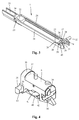
- FIG. 1 is a partial longitudinal section of a rifle executed here as a gas pressure rifle with a system box or closure housing 1, attached to the closure housing 1 gun barrel 2 and a forearm 3 shown.
- a guide rod 4 protruding forwardly as viewed in the weft direction and parallel to the axis of the barrel of the gun barrel is fastened.
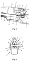
- guide rod 4 On the forward freely cantilevered and not attached to the gun barrel 2 guide rod 4 is in the Figures 2 and 3 shown in different perspectives and explained in more detail below shutter actuation device 5 for moving a closure body 6 slidably guided.
- a shutter spring 7 is also arranged, via which the shutter actuator 5 is pressed forward.
- About an external thread 8 at the front free end of the guide rod 4 and provided with a corresponding internal thread threaded sleeve 9 of the fore-end 3 is fixed with its front end seen in the weft direction on the guide rod 4.
- the gun barrel 2 has an attachable to the closure housing 1 and firmly connectable with this rear part 10 and a freely projecting from the closure housing 1 front part 11.
- an ejection window 12 is provided at the opposite the front part 11 in diameter enlarged rear part 10 of the gun barrel 2 for the cartridge ejection.
- the rear part 10 seen in the weft direction and the front part 11 of the gun barrel 2 are made in one piece in the embodiment shown.
- the two parts 10 and 11 of the gun barrel 2 can also be manufactured as individual parts, put together and firmly connected to each other, for example by soldering or other suitable connection.
- two radially projecting retaining bolts 13 are provided on the resting on the closure housing 1 rear part 10 of the barrel 2.
- the retaining bolts 13 provided with an external thread can be inserted radially into the rear part 10 of the gun barrel 2 or can be formed directly on the gun barrel 2.
- the retaining bolts 13 are designed to engage in two juxtaposed bores 14 in a projecting bearing part 15 of the closure housing 1.
- the gas sampling block 17 has a gas cylinder 18 with a gas discharge opening 19 opening into the barrel 2 and a pressure piston 20 guided axially displaceably in the gas cylinder 18.
- the plunger 20 includes a projecting through a rear bore in the gas sampling block 17 piston rod 21 which cooperates with the shutter actuator 5 to the displacement in the longitudinal direction of the rifle.
- shutter actuator 5 comprises a slidably guided on the guide rod 4 carrier 22 and two fixed to the carrier 22 via a transverse pin 23 push rods 24.
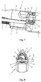
- rear free ends of the two rail-shaped push rods 24 is on the upper side one with lateral lugs 25th on the closure body 6 cooperating cam with a recess 26, an obliquely upwardly extending locking ramp 27 and an upper control surface 28 is provided.
- the push rods 24 designed as rails have in the rear end region opposite thickenings 29 with transverse bores 30 for a control element 31 designed here as a transverse pin.
- a laterally projecting locking handle 32 is formed on the pin-shaped control element 31, a laterally projecting locking handle 32 is formed.
- the carrier 22 includes at its seen in the weft direction front part of a U-shaped cross-section with a receptacle 33 and a rear abutment 34 for the piston rod 21 of the plunger 20.
- a receptacle 33 and a rear abutment 34 for the piston rod 21 of the plunger 20 In the upwardly open receptacle 33 of the carrier 22 of the gas extraction block 17 during installation of the gun barrel 2 is easily inserted.
- FIG. 4 the closure body 6 is shown. This has in addition to the laterally projecting lugs 25 on an upwardly projecting locking block 35. At the two lugs 25 and the locking block 35 rear locking surfaces 36 and 37 are provided. At the back of the closure body 6, a striking plate 38 and an ejector 39 are also arranged. Transversely through the closure body 6 extends a continuous control opening 40 with a lower control surface 41 and an obliquely upward Entriegelungsrampe 42nd
- FIG. 4 By shifting the in FIG. 3
- the shutter actuator 5 shown in the longitudinal direction of the self-loading weapon is the in FIG. 4 shown closure body 6 between a in the FIGS. 5 and 6 shown upper locking position and one in the FIGS. 7 and 8 shown lower unlocking position movable.
- the closing body 6 is moved via the pin-shaped control element 31 and the unlocking ramp 42 to the passage opening 40 of the closing body 6 down in the in the FIGS. 7 and 8 shown unlocked position moves.
- the lateral projections 25 are disengaged from the lateral grooves 44 and rest in the recess 26 of the push rods 24.
- the closure block 35 of the closure body 6 is disengaged from the locking groove 43 on the gun barrel 2, so that the closure body 6 can move further to the rear.
- the cartridge case by means of a arranged on the front of the closure body 6, in FIG. 14 shown, extractor 55 pulled out of the chamber and over the in FIG. 4 shown ejector 39 are ejected through the ejection window 12.
- the shutter actuating device 5 is slidably guided via the strip-shaped push rods 24 between upper guide surfaces 45 on the system box or closure housing 1 and lower guide surfaces 46 on the rear part 12 of the gun barrel 2.
- the closure handle 32 is made in one piece with the pin-shaped control element 31.
- the control element 31 and the closure handle 32 can also be designed as separate parts which are firmly connected to one another.
- FIGS. 9 to 11 Demontagetechnisch 47 shown in detail for safe mounting and prevention of unwanted disassembly of the pin-shaped control 31 arranged.
- the dismantling safety device 47 comprises a locking pin 48 arranged at right angles to the pin-shaped control element 31, which in one also extends into a locking pin 48 FIG. 3 shown, to the top of the push rod 24 open towards blind hole 49 is arranged at the rear end of the left push rod 24 seen in the weft direction.
- the locking pin 48 is within the blind hole 49 via a lateral longitudinal groove 50 and a perpendicular thereto retaining pin 51 between a in FIG. 10 illustrated lower securing position and a in FIG. 11 shown upper disassembly position slidably guided and is pressed by a compression spring 52 upwards in the disassembly position.
- the locking pin 48 has on its side opposite the longitudinal groove 50 a recess 53 with a matched to the personallyachir of the control element 31 radius.
- the pin-shaped control element 31 includes at its end opposite the closure handle 32 a locking pin 48 facing indentation 54, which also in the Figures 5 and 7 is shown.
- the recess 53 on the locking pin 48 is arranged such that it in the lower securing position of the locking pin 48 below the central axis of the pin-shaped Control element 31 is located and the locking pin 48 engages with its cylindrical upper end in the recess 54 of the pin-shaped control element 31.
- pulling out of the pin-shaped control element 31 can be prevented in the lower securing position of the securing pin 48.
- the locking pin 48 by the compression spring 52 in the in FIG. 11 get shown disassembly position.
- the recess 53 in the locking pin 48 is arranged such that it in the disassembly position of FIG. 11 is at the height of the central axis of the pin-shaped control element 31 and thus the pin-shaped control element 31 can be pulled out.
- FIGS. 12 and 13 It can be seen that on the sleeve bottom 56 of a cartridge case 57 facing the front of the closure body 6, a radially movable sleeve holder 58 is arranged.
- the sleeve holder 58 which is movable at right angles to the longitudinal axis of the closure body 6, is displaceable on the inside of the sleeve holder 58 between two detent positions via a ball catch with a detent ball 59 arranged in the closure body 6 and acted upon by a spring and two detents 60 and 61.
- the cartridge case 57 is held even in the height of the cartridge chamber, when the closure body 6 transversely to the longitudinal axis of the barrel between the in FIG. 12 shown upper locking position and the in FIG. 13 moved shown lower unlocking position.
- the sleeve holder 58 is according to FIG. 14 guided displaceably in a radial groove 62 on the front side of the closure body 6 and has at its radially inner end a bearing surface 63 for resting against the underside of the sleeve bottom 56.
- a further radial groove 64 at the front of the closure body 6 and the extractor 55 is guided radially movable.
- the empty cartridge case is ejected via the ejection window 12 and the lock is tensioned. Then a new cartridge can be brought over the magazine spring of a magazine on the level of the cartridge chamber.
- the closure body 6 is pressed over the shutter actuator 5 with the carrier 22 and the two push rods 24 forward and thereby the new cartridge in the cartridge chamber.
- the closure body 6 passes via the locking ramps 27 on the push rods 24 back into the locking position and the closure is closed.
- slopes 65 may be provided with a slope corresponding to the locking ramps 27.
- the locking pin 48 of the disassembly fuse 47 also enters the upper disassembly position, so that the pin-shaped control element 31 can be pulled out via the closure handle 32 and the closure body 6 can thereby be dismantled.
- the invention is not limited to the gas-pressure rifle described above. It can also be used in other self-loading rifles, repeating rifles or other rifles.
Landscapes
- Engineering & Computer Science (AREA)
- General Engineering & Computer Science (AREA)
- Toys (AREA)
- Telescopes (AREA)
- Portable Nailing Machines And Staplers (AREA)
Applications Claiming Priority (1)
| Application Number | Priority Date | Filing Date | Title |
|---|---|---|---|
| DE102015108125.3A DE102015108125A1 (de) | 2015-05-22 | 2015-05-22 | Verschluss für ein Gewehr |
Publications (3)
| Publication Number | Publication Date |
|---|---|
| EP3096107A2 true EP3096107A2 (fr) | 2016-11-23 |
| EP3096107A3 EP3096107A3 (fr) | 2017-02-15 |
| EP3096107B1 EP3096107B1 (fr) | 2018-07-04 |
Family
ID=55650182
Family Applications (1)
| Application Number | Title | Priority Date | Filing Date |
|---|---|---|---|
| EP16161863.2A Active EP3096107B1 (fr) | 2015-05-22 | 2016-03-23 | Mecanisme de culasse pour arme |
Country Status (5)
| Country | Link |
|---|---|
| US (1) | US9879929B2 (fr) |
| EP (1) | EP3096107B1 (fr) |
| DE (1) | DE102015108125A1 (fr) |
| ES (1) | ES2687173T3 (fr) |
| RU (1) | RU2661257C2 (fr) |
Cited By (2)
| Publication number | Priority date | Publication date | Assignee | Title |
|---|---|---|---|---|
| CZ310058B6 (cs) * | 2023-02-28 | 2024-06-26 | Jan Leimer | Sestava závěru a hlavně střelné zbraně a střelná zbraň s touto sestavou |
| US12540783B2 (en) | 2023-03-30 | 2026-02-03 | Blaser Group Gmbh | Bolt head of a breech block and breech block with such a bolt head |
Families Citing this family (1)
| Publication number | Priority date | Publication date | Assignee | Title |
|---|---|---|---|---|
| WO2024196589A2 (fr) | 2023-03-21 | 2024-09-26 | Sturm, Ruger & Company, Inc. | Poignée de charge latérale pour arme à feu semi-automatique |
Family Cites Families (19)
| Publication number | Priority date | Publication date | Assignee | Title |
|---|---|---|---|---|
| US1363262A (en) * | 1918-06-14 | 1920-12-28 | Vickers Ltd | Rifle and machine-gun |
| US2077415A (en) * | 1935-07-26 | 1937-04-20 | William E House | Gun |
| US2373213A (en) * | 1943-02-26 | 1945-04-10 | Western Cartridge Co | Receiver-assembly for firearms |
| US3200710A (en) * | 1963-12-27 | 1965-08-17 | Remington Arms Co Inc | Gas operating mechanism for autoloading firearm |
| ES379338A1 (es) * | 1969-04-29 | 1973-04-16 | Beretta Armi Spa | Perfeccionamientos en los fusiles automaticos. |
| US3816950A (en) * | 1973-02-20 | 1974-06-18 | E Vesamaa | Self-locking cocking pin in firearms with closure by rotation |
| US4014247A (en) * | 1974-11-19 | 1977-03-29 | Ithaca Gun Company, Inc. | Gas-operated shotgun |
| US4161836A (en) * | 1976-11-25 | 1979-07-24 | Kabushiki Kaisha Kawaguchiya Hayashi Juho Kayaku-Ten | Breechblock assembly and an operating mechanism for a fire-arm automatic loading |
| US4213261A (en) * | 1978-06-27 | 1980-07-22 | James P. Claypool | Breech locking mechanism |
| US5913262A (en) * | 1997-08-06 | 1999-06-15 | Sommer + Ockenfuss Gmbh | Breech for barrel-type firearms |
| DE19836964C1 (de) * | 1998-08-14 | 1999-12-02 | Sommer & Ockenfus Gmbh | Verschluß für Rohrwaffen |
| DE202004006496U1 (de) * | 2004-04-21 | 2005-09-01 | Rud-Kettenfabrik Rieger & Dietz Gmbh U. Co. | Tragbolzen |
| DE102004023555B4 (de) * | 2004-05-13 | 2008-07-24 | S.A.T. Swiss Arms Technology Ag | Repetierwaffe |
| BE1016821A3 (fr) * | 2005-10-25 | 2007-07-03 | Browning Int Sa | Carabine semi-automatique amelioree |
| ITMI20071909A1 (it) * | 2007-10-04 | 2009-04-05 | Beretta Armi Spa | Arma da fuoco con gruppo otturatore perfezionato |
| US7469624B1 (en) * | 2007-11-12 | 2008-12-30 | Jason Adams | Direct drive retrofit for rifles |
| DE102011010940B4 (de) * | 2011-02-11 | 2012-10-25 | Blaser Finanzholding Gmbh | Vorrichtung zur Bettung eines Verschlussgehäuses und/oder eines Laufs in einem Schaft einer Handfeuerwaffe |
| US8800422B2 (en) * | 2012-08-20 | 2014-08-12 | Ra Brands, L.L.C. | Bolt assembly for firearms |
| DE102014109567A1 (de) * | 2014-07-09 | 2016-01-14 | L&O Hunting Group GmbH | Gasdruckladegewehr |
-
2015
- 2015-05-22 DE DE102015108125.3A patent/DE102015108125A1/de not_active Withdrawn
-
2016
- 2016-03-23 ES ES16161863.2T patent/ES2687173T3/es active Active
- 2016-03-23 EP EP16161863.2A patent/EP3096107B1/fr active Active
- 2016-05-16 RU RU2016118751A patent/RU2661257C2/ru active
- 2016-05-17 US US15/156,467 patent/US9879929B2/en active Active
Non-Patent Citations (1)
| Title |
|---|
| None |
Cited By (2)
| Publication number | Priority date | Publication date | Assignee | Title |
|---|---|---|---|---|
| CZ310058B6 (cs) * | 2023-02-28 | 2024-06-26 | Jan Leimer | Sestava závěru a hlavně střelné zbraně a střelná zbraň s touto sestavou |
| US12540783B2 (en) | 2023-03-30 | 2026-02-03 | Blaser Group Gmbh | Bolt head of a breech block and breech block with such a bolt head |
Also Published As
| Publication number | Publication date |
|---|---|
| EP3096107A3 (fr) | 2017-02-15 |
| US9879929B2 (en) | 2018-01-30 |
| RU2661257C2 (ru) | 2018-07-13 |
| ES2687173T3 (es) | 2018-10-24 |
| EP3096107B1 (fr) | 2018-07-04 |
| US20160341500A1 (en) | 2016-11-24 |
| RU2016118751A (ru) | 2017-11-21 |
| DE102015108125A1 (de) | 2016-11-24 |
Similar Documents
| Publication | Publication Date | Title |
|---|---|---|
| EP1830152B1 (fr) | Chargeur enfichable pour arme à feu | |
| EP3011253B1 (fr) | Kit de conversion d'arme à feu ainsi que procédé de conversion d'une arme à feu | |
| DE3872335T2 (de) | Verschluss-verriegelung fuer selbstladende pistolen. | |
| EP2157393B1 (fr) | Pistolet automatique | |
| EP3591329B1 (fr) | Poignée d'arme ou boîtier d'arme pour arme à feu à chargement automatique pourvu d'un arrêt de culasse et arme à feu à chargement automatique comportant une telle poignée d'arme ou un tel boîtier d'arme | |
| DE10392631T5 (de) | Monolithische Schienenplattform und Verschlussbaugruppen für eine Feuerwaffe | |
| AT512057B1 (de) | Anbau-schussgerät | |
| EP2966397B1 (fr) | Fusil à emprunt de gaz | |
| EP1596151A1 (fr) | Arme à feu à répétition | |
| EP3096107B1 (fr) | Mecanisme de culasse pour arme | |
| EP1500897B1 (fr) | Culasse pour arme à feu semi-automatique | |
| DE1225517B (de) | Schulterstuetze fuer Handfeuerwaffen | |
| DE1067377B (de) | Bolzensetzgerat | |
| DE102007011504B4 (de) | Handfeuerwaffe | |
| EP1379827B1 (fr) | Dispositif pour extraire des cartouches et/ou des douilles d'une arme a canon basculant | |
| DE202014103141U1 (de) | Gasdruckladegewehr | |
| DE202015102639U1 (de) | Verschluss für ein Gewehr | |
| DE10051708B4 (de) | Selbstladepistole | |
| AT528395B1 (de) | Handfeuerwaffe mit tiefliegendem Lauf und Drehlaufverriegelungssystem | |
| EP3176535B1 (fr) | Fusil avec mécanisme de percussion | |
| DE202006003351U1 (de) | Steckmagazin einer Handfeuerwaffe | |
| DE8418572U1 (de) | Dichtungsvorrichtung für einen Verschluß an großkalibrigen Waffen | |
| DE202015102638U1 (de) | Gewehr | |
| DE84431C (fr) | ||
| DE2004968C3 (de) | Selbstladende Feuerwaffe |
Legal Events
| Date | Code | Title | Description |
|---|---|---|---|
| PUAI | Public reference made under article 153(3) epc to a published international application that has entered the european phase |
Free format text: ORIGINAL CODE: 0009012 |
|
| AK | Designated contracting states |
Kind code of ref document: A2 Designated state(s): AL AT BE BG CH CY CZ DE DK EE ES FI FR GB GR HR HU IE IS IT LI LT LU LV MC MK MT NL NO PL PT RO RS SE SI SK SM TR |
|
| AX | Request for extension of the european patent |
Extension state: BA ME |
|
| PUAL | Search report despatched |
Free format text: ORIGINAL CODE: 0009013 |
|
| AK | Designated contracting states |
Kind code of ref document: A3 Designated state(s): AL AT BE BG CH CY CZ DE DK EE ES FI FR GB GR HR HU IE IS IT LI LT LU LV MC MK MT NL NO PL PT RO RS SE SI SK SM TR |
|
| AX | Request for extension of the european patent |
Extension state: BA ME |
|
| RIC1 | Information provided on ipc code assigned before grant |
Ipc: F41A 3/34 20060101ALI20170111BHEP Ipc: F41A 3/72 20060101AFI20170111BHEP Ipc: F41A 5/18 20060101ALI20170111BHEP Ipc: F41A 21/48 20060101ALN20170111BHEP |
|
| STAA | Information on the status of an ep patent application or granted ep patent |
Free format text: STATUS: REQUEST FOR EXAMINATION WAS MADE |
|
| 17P | Request for examination filed |
Effective date: 20170816 |
|
| RBV | Designated contracting states (corrected) |
Designated state(s): AL AT BE BG CH CY CZ DE DK EE ES FI FR GB GR HR HU IE IS IT LI LT LU LV MC MK MT NL NO PL PT RO RS SE SI SK SM TR |
|
| GRAP | Despatch of communication of intention to grant a patent |
Free format text: ORIGINAL CODE: EPIDOSNIGR1 |
|
| STAA | Information on the status of an ep patent application or granted ep patent |
Free format text: STATUS: GRANT OF PATENT IS INTENDED |
|
| RIC1 | Information provided on ipc code assigned before grant |
Ipc: F41A 5/18 20060101ALI20180124BHEP Ipc: F41A 3/34 20060101ALI20180124BHEP Ipc: F41A 21/48 20060101ALN20180124BHEP Ipc: F41A 3/72 20060101AFI20180124BHEP |
|
| INTG | Intention to grant announced |
Effective date: 20180215 |
|
| GRAS | Grant fee paid |
Free format text: ORIGINAL CODE: EPIDOSNIGR3 |
|
| GRAA | (expected) grant |
Free format text: ORIGINAL CODE: 0009210 |
|
| STAA | Information on the status of an ep patent application or granted ep patent |
Free format text: STATUS: THE PATENT HAS BEEN GRANTED |
|
| AK | Designated contracting states |
Kind code of ref document: B1 Designated state(s): AL AT BE BG CH CY CZ DE DK EE ES FI FR GB GR HR HU IE IS IT LI LT LU LV MC MK MT NL NO PL PT RO RS SE SI SK SM TR |
|
| REG | Reference to a national code |
Ref country code: GB Ref legal event code: FG4D Free format text: NOT ENGLISH |
|
| REG | Reference to a national code |
Ref country code: CH Ref legal event code: EP |
|
| REG | Reference to a national code |
Ref country code: AT Ref legal event code: REF Ref document number: 1014970 Country of ref document: AT Kind code of ref document: T Effective date: 20180715 |
|
| REG | Reference to a national code |
Ref country code: IE Ref legal event code: FG4D Free format text: LANGUAGE OF EP DOCUMENT: GERMAN |
|
| REG | Reference to a national code |
Ref country code: DE Ref legal event code: R096 Ref document number: 502016001379 Country of ref document: DE |
|
| REG | Reference to a national code |
Ref country code: SE Ref legal event code: TRGR |
|
| REG | Reference to a national code |
Ref country code: ES Ref legal event code: FG2A Ref document number: 2687173 Country of ref document: ES Kind code of ref document: T3 Effective date: 20181024 |
|
| REG | Reference to a national code |
Ref country code: NL Ref legal event code: MP Effective date: 20180704 |
|
| REG | Reference to a national code |
Ref country code: LT Ref legal event code: MG4D |
|
| PG25 | Lapsed in a contracting state [announced via postgrant information from national office to epo] |
Ref country code: NL Free format text: LAPSE BECAUSE OF FAILURE TO SUBMIT A TRANSLATION OF THE DESCRIPTION OR TO PAY THE FEE WITHIN THE PRESCRIBED TIME-LIMIT Effective date: 20180704 |
|
| PG25 | Lapsed in a contracting state [announced via postgrant information from national office to epo] |
Ref country code: LT Free format text: LAPSE BECAUSE OF FAILURE TO SUBMIT A TRANSLATION OF THE DESCRIPTION OR TO PAY THE FEE WITHIN THE PRESCRIBED TIME-LIMIT Effective date: 20180704 Ref country code: PL Free format text: LAPSE BECAUSE OF FAILURE TO SUBMIT A TRANSLATION OF THE DESCRIPTION OR TO PAY THE FEE WITHIN THE PRESCRIBED TIME-LIMIT Effective date: 20180704 Ref country code: RS Free format text: LAPSE BECAUSE OF FAILURE TO SUBMIT A TRANSLATION OF THE DESCRIPTION OR TO PAY THE FEE WITHIN THE PRESCRIBED TIME-LIMIT Effective date: 20180704 Ref country code: IS Free format text: LAPSE BECAUSE OF FAILURE TO SUBMIT A TRANSLATION OF THE DESCRIPTION OR TO PAY THE FEE WITHIN THE PRESCRIBED TIME-LIMIT Effective date: 20181104 Ref country code: BG Free format text: LAPSE BECAUSE OF FAILURE TO SUBMIT A TRANSLATION OF THE DESCRIPTION OR TO PAY THE FEE WITHIN THE PRESCRIBED TIME-LIMIT Effective date: 20181004 Ref country code: NO Free format text: LAPSE BECAUSE OF FAILURE TO SUBMIT A TRANSLATION OF THE DESCRIPTION OR TO PAY THE FEE WITHIN THE PRESCRIBED TIME-LIMIT Effective date: 20181004 Ref country code: GR Free format text: LAPSE BECAUSE OF FAILURE TO SUBMIT A TRANSLATION OF THE DESCRIPTION OR TO PAY THE FEE WITHIN THE PRESCRIBED TIME-LIMIT Effective date: 20181005 |
|
| PG25 | Lapsed in a contracting state [announced via postgrant information from national office to epo] |
Ref country code: HR Free format text: LAPSE BECAUSE OF FAILURE TO SUBMIT A TRANSLATION OF THE DESCRIPTION OR TO PAY THE FEE WITHIN THE PRESCRIBED TIME-LIMIT Effective date: 20180704 Ref country code: AL Free format text: LAPSE BECAUSE OF FAILURE TO SUBMIT A TRANSLATION OF THE DESCRIPTION OR TO PAY THE FEE WITHIN THE PRESCRIBED TIME-LIMIT Effective date: 20180704 Ref country code: LV Free format text: LAPSE BECAUSE OF FAILURE TO SUBMIT A TRANSLATION OF THE DESCRIPTION OR TO PAY THE FEE WITHIN THE PRESCRIBED TIME-LIMIT Effective date: 20180704 |
|
| REG | Reference to a national code |
Ref country code: DE Ref legal event code: R097 Ref document number: 502016001379 Country of ref document: DE |
|
| PG25 | Lapsed in a contracting state [announced via postgrant information from national office to epo] |
Ref country code: RO Free format text: LAPSE BECAUSE OF FAILURE TO SUBMIT A TRANSLATION OF THE DESCRIPTION OR TO PAY THE FEE WITHIN THE PRESCRIBED TIME-LIMIT Effective date: 20180704 Ref country code: EE Free format text: LAPSE BECAUSE OF FAILURE TO SUBMIT A TRANSLATION OF THE DESCRIPTION OR TO PAY THE FEE WITHIN THE PRESCRIBED TIME-LIMIT Effective date: 20180704 |
|
| PLBE | No opposition filed within time limit |
Free format text: ORIGINAL CODE: 0009261 |
|
| STAA | Information on the status of an ep patent application or granted ep patent |
Free format text: STATUS: NO OPPOSITION FILED WITHIN TIME LIMIT |
|
| PG25 | Lapsed in a contracting state [announced via postgrant information from national office to epo] |
Ref country code: SM Free format text: LAPSE BECAUSE OF FAILURE TO SUBMIT A TRANSLATION OF THE DESCRIPTION OR TO PAY THE FEE WITHIN THE PRESCRIBED TIME-LIMIT Effective date: 20180704 Ref country code: SK Free format text: LAPSE BECAUSE OF FAILURE TO SUBMIT A TRANSLATION OF THE DESCRIPTION OR TO PAY THE FEE WITHIN THE PRESCRIBED TIME-LIMIT Effective date: 20180704 Ref country code: DK Free format text: LAPSE BECAUSE OF FAILURE TO SUBMIT A TRANSLATION OF THE DESCRIPTION OR TO PAY THE FEE WITHIN THE PRESCRIBED TIME-LIMIT Effective date: 20180704 |
|
| 26N | No opposition filed |
Effective date: 20190405 |
|
| PG25 | Lapsed in a contracting state [announced via postgrant information from national office to epo] |
Ref country code: SI Free format text: LAPSE BECAUSE OF FAILURE TO SUBMIT A TRANSLATION OF THE DESCRIPTION OR TO PAY THE FEE WITHIN THE PRESCRIBED TIME-LIMIT Effective date: 20180704 |
|
| PG25 | Lapsed in a contracting state [announced via postgrant information from national office to epo] |
Ref country code: MC Free format text: LAPSE BECAUSE OF FAILURE TO SUBMIT A TRANSLATION OF THE DESCRIPTION OR TO PAY THE FEE WITHIN THE PRESCRIBED TIME-LIMIT Effective date: 20180704 |
|
| REG | Reference to a national code |
Ref country code: CH Ref legal event code: PL |
|
| PG25 | Lapsed in a contracting state [announced via postgrant information from national office to epo] |
Ref country code: LU Free format text: LAPSE BECAUSE OF NON-PAYMENT OF DUE FEES Effective date: 20190323 |
|
| PG25 | Lapsed in a contracting state [announced via postgrant information from national office to epo] |
Ref country code: LI Free format text: LAPSE BECAUSE OF NON-PAYMENT OF DUE FEES Effective date: 20190331 Ref country code: IE Free format text: LAPSE BECAUSE OF NON-PAYMENT OF DUE FEES Effective date: 20190323 Ref country code: CH Free format text: LAPSE BECAUSE OF NON-PAYMENT OF DUE FEES Effective date: 20190331 |
|
| PG25 | Lapsed in a contracting state [announced via postgrant information from national office to epo] |
Ref country code: TR Free format text: LAPSE BECAUSE OF FAILURE TO SUBMIT A TRANSLATION OF THE DESCRIPTION OR TO PAY THE FEE WITHIN THE PRESCRIBED TIME-LIMIT Effective date: 20180704 |
|
| PG25 | Lapsed in a contracting state [announced via postgrant information from national office to epo] |
Ref country code: MT Free format text: LAPSE BECAUSE OF FAILURE TO SUBMIT A TRANSLATION OF THE DESCRIPTION OR TO PAY THE FEE WITHIN THE PRESCRIBED TIME-LIMIT Effective date: 20180704 Ref country code: PT Free format text: LAPSE BECAUSE OF FAILURE TO SUBMIT A TRANSLATION OF THE DESCRIPTION OR TO PAY THE FEE WITHIN THE PRESCRIBED TIME-LIMIT Effective date: 20181104 |
|
| GBPC | Gb: european patent ceased through non-payment of renewal fee |
Effective date: 20200323 |
|
| PG25 | Lapsed in a contracting state [announced via postgrant information from national office to epo] |
Ref country code: GB Free format text: LAPSE BECAUSE OF NON-PAYMENT OF DUE FEES Effective date: 20200323 |
|
| PG25 | Lapsed in a contracting state [announced via postgrant information from national office to epo] |
Ref country code: CY Free format text: LAPSE BECAUSE OF FAILURE TO SUBMIT A TRANSLATION OF THE DESCRIPTION OR TO PAY THE FEE WITHIN THE PRESCRIBED TIME-LIMIT Effective date: 20180704 |
|
| PG25 | Lapsed in a contracting state [announced via postgrant information from national office to epo] |
Ref country code: HU Free format text: LAPSE BECAUSE OF FAILURE TO SUBMIT A TRANSLATION OF THE DESCRIPTION OR TO PAY THE FEE WITHIN THE PRESCRIBED TIME-LIMIT; INVALID AB INITIO Effective date: 20160323 |
|
| REG | Reference to a national code |
Ref country code: DE Ref legal event code: R081 Ref document number: 502016001379 Country of ref document: DE Owner name: BLASER GROUP GMBH, DE Free format text: FORMER OWNER: L&O HUNTING GROUP GMBH, 88316 ISNY, DE |
|
| PG25 | Lapsed in a contracting state [announced via postgrant information from national office to epo] |
Ref country code: MK Free format text: LAPSE BECAUSE OF FAILURE TO SUBMIT A TRANSLATION OF THE DESCRIPTION OR TO PAY THE FEE WITHIN THE PRESCRIBED TIME-LIMIT Effective date: 20180704 |
|
| PGFP | Annual fee paid to national office [announced via postgrant information from national office to epo] |
Ref country code: DE Payment date: 20250415 Year of fee payment: 10 |
|
| PGFP | Annual fee paid to national office [announced via postgrant information from national office to epo] |
Ref country code: ES Payment date: 20250416 Year of fee payment: 10 |
|
| PGFP | Annual fee paid to national office [announced via postgrant information from national office to epo] |
Ref country code: IT Payment date: 20250331 Year of fee payment: 10 |
|
| PGFP | Annual fee paid to national office [announced via postgrant information from national office to epo] |
Ref country code: SE Payment date: 20260323 Year of fee payment: 11 |
|
| PGFP | Annual fee paid to national office [announced via postgrant information from national office to epo] |
Ref country code: AT Payment date: 20260319 Year of fee payment: 11 |
|
| PGFP | Annual fee paid to national office [announced via postgrant information from national office to epo] |
Ref country code: BE Payment date: 20260323 Year of fee payment: 11 Ref country code: FI Payment date: 20260320 Year of fee payment: 11 |
|
| PGFP | Annual fee paid to national office [announced via postgrant information from national office to epo] |
Ref country code: FR Payment date: 20260324 Year of fee payment: 11 |
|
| PGFP | Annual fee paid to national office [announced via postgrant information from national office to epo] |
Ref country code: CZ Payment date: 20260311 Year of fee payment: 11 |