EP3096132A1 - Vorrichtung zum abtasten von turbinenschaufeln - Google Patents
Vorrichtung zum abtasten von turbinenschaufeln Download PDFInfo
- Publication number
- EP3096132A1 EP3096132A1 EP16168887.4A EP16168887A EP3096132A1 EP 3096132 A1 EP3096132 A1 EP 3096132A1 EP 16168887 A EP16168887 A EP 16168887A EP 3096132 A1 EP3096132 A1 EP 3096132A1
- Authority
- EP
- European Patent Office
- Prior art keywords
- blades
- axis
- rotation
- blade
- support
- Prior art date
- Legal status (The legal status is an assumption and is not a legal conclusion. Google has not performed a legal analysis and makes no representation as to the accuracy of the status listed.)
- Withdrawn
Links
- 238000002591 computed tomography Methods 0.000 claims abstract description 23
- 230000002093 peripheral effect Effects 0.000 claims abstract description 14
- 239000000463 material Substances 0.000 claims description 19
- 239000011347 resin Substances 0.000 claims description 3
- 229920005989 resin Polymers 0.000 claims description 3
- 238000004458 analytical method Methods 0.000 claims description 2
- 238000000034 method Methods 0.000 abstract description 43
- PXHVJJICTQNCMI-UHFFFAOYSA-N Nickel Chemical compound [Ni] PXHVJJICTQNCMI-UHFFFAOYSA-N 0.000 description 4
- 238000003491 array Methods 0.000 description 3
- 230000004323 axial length Effects 0.000 description 3
- 238000007689 inspection Methods 0.000 description 2
- 238000004519 manufacturing process Methods 0.000 description 2
- 229910052759 nickel Inorganic materials 0.000 description 2
- 229910000601 superalloy Inorganic materials 0.000 description 2
- 229910000831 Steel Inorganic materials 0.000 description 1
- 229910001315 Tool steel Inorganic materials 0.000 description 1
- 230000002411 adverse Effects 0.000 description 1
- 238000012790 confirmation Methods 0.000 description 1
- 238000005516 engineering process Methods 0.000 description 1
- 238000012986 modification Methods 0.000 description 1
- 230000004048 modification Effects 0.000 description 1
- 230000003014 reinforcing effect Effects 0.000 description 1
- 239000010959 steel Substances 0.000 description 1
- 230000000007 visual effect Effects 0.000 description 1
Images




Classifications
-
- G—PHYSICS
- G01—MEASURING; TESTING
- G01N—INVESTIGATING OR ANALYSING MATERIALS BY DETERMINING THEIR CHEMICAL OR PHYSICAL PROPERTIES
- G01N23/00—Investigating or analysing materials by the use of wave or particle radiation, e.g. X-rays or neutrons, not covered by groups G01N3/00 – G01N17/00, G01N21/00 or G01N22/00
- G01N23/02—Investigating or analysing materials by the use of wave or particle radiation, e.g. X-rays or neutrons, not covered by groups G01N3/00 – G01N17/00, G01N21/00 or G01N22/00 by transmitting the radiation through the material
- G01N23/04—Investigating or analysing materials by the use of wave or particle radiation, e.g. X-rays or neutrons, not covered by groups G01N3/00 – G01N17/00, G01N21/00 or G01N22/00 by transmitting the radiation through the material and forming images of the material
- G01N23/046—Investigating or analysing materials by the use of wave or particle radiation, e.g. X-rays or neutrons, not covered by groups G01N3/00 – G01N17/00, G01N21/00 or G01N22/00 by transmitting the radiation through the material and forming images of the material using tomography, e.g. computed tomography [CT]
-
- G—PHYSICS
- G01—MEASURING; TESTING
- G01N—INVESTIGATING OR ANALYSING MATERIALS BY DETERMINING THEIR CHEMICAL OR PHYSICAL PROPERTIES
- G01N2223/00—Investigating materials by wave or particle radiation
- G01N2223/40—Imaging
- G01N2223/419—Imaging computed tomograph
-
- G—PHYSICS
- G01—MEASURING; TESTING
- G01N—INVESTIGATING OR ANALYSING MATERIALS BY DETERMINING THEIR CHEMICAL OR PHYSICAL PROPERTIES
- G01N2223/00—Investigating materials by wave or particle radiation
- G01N2223/60—Specific applications or type of materials
- G01N2223/63—Specific applications or type of materials turbine blades
Definitions
- the present invention relates to a method of scanning aerofoil blades, and more particularly relates to a method of CT scanning a plurality of aerofoil blades.
- Computed tomography is now a widely available technology, and it has been proposed previously to use the CT techniques for investigative work on the internal geometry of aerofoil blades, and in particular turbine blades for gas turbine engines.
- a method of CT scanning a plurality of aerofoil blades may include the steps of; providing a rotatable support arranged for rotation about an axis of rotation and within an energy beam; mounting a plurality of aerofoil blades to the support in spaced-apart relationship to one another so as to form at least one array around the axis of rotation; and rotating the support about the axis within the beam; wherein each blade has an aerofoil section and is mounted to the support such that the span of its aerofoil section is substantially parallel to the axis of rotation, wherein the method also involves providing an elongate identification element on the rotatable support, the identification element being arranged such that its longitudinal axis is substantially parallel to the axis of rotation and having a transverse cross-sectional shape along at least part of its length which includes a plurality of different peripheral edge features, each said edge feature corresponding to and being directed towards a respective said blade to thereby facilitate identification of individual said blades in
- said identification element is provided in the form of a pillar fixed to the rotatable support.
- said identification element is arranged such that its longitudinal axis is substantially coincident with the axis of rotation of the support such that the blades in the or each said array are arranged around the identification element.
- said cross-sectional shape of the identification element is substantially polygonal and has a number of sides equal to the number of aerofoil blades in the or each said array.
- each said side is arranged in facing relation to a respective said blade.
- either all, or all except one, of said sides has a respective said peripheral edge feature formed along its length.
- said peripheral edge features include at least one of recesses and projections.
- said peripheral edge features are configured so as to be visible both on the exterior of the identification element and in said CT output obtained via the method.
- At least one of said peripheral edge features is configured such that its cross-sectional shape varies along at least part of the length of the identification element, and wherein the method involves analysing the configuration of the or each said edge feature visible in said CT output to determine the axial position of a CT slice taken through said blades and said identification element.
- said identification element is formed of material having a density which is lower than that of the material from which the blades are formed.
- said identification element is formed from a resin.
- said identification element is formed from a polymeric material.
- the method further involves the provision of a datum element on the rotatable support, the datum element being configured so as have an end surface arranged orthogonal to the axis of rotation and spaced from the support by a predetermined distance.
- the method involves taking a datum CT scan in the form of a slice through the blades and orthogonal to the axis of rotation at a position spaced from the support by said predetermined distance such that the end surface of the datum element appears in the resulting CT image, and thereafter taking subsequent CT scans in the form of respective parallel slices through the blades at predetermined offset distances from said datum scan.
- said datum element is provided in the form of an elongate pillar fixed to the rotatable support.
- said datum pillar is arranged such that its longitudinal axis is substantially parallel to the axis of rotation of the rotatable support.
- said datum pillar is provided within said array of blades such that said blades are arranged around the datum pillar.
- said datum element is formed from a material having a similar density to the material from which the blades are formed.
- said datum element is formed from steel.
- the method including the steps of: providing a rotatable support arranged for rotation about an axis of rotation and within an energy beam; mounting a plurality of aerofoil blades to the support in spaced-apart relationship to one another so as to form at least one array around the axis of rotation; and rotating the support about the axis within the beam; wherein each blade has an aerofoil section and is mounted to the support such that the span of its aerofoil section is substantially parallel to the axis of rotation, the blades being arranged such that no line orthogonal to the axis of rotation intersects the aerofoil section of more than one blade.
- said step of mounting a plurality of blades to the support involves forming a plurality of said arrays of blades; the arrays being spaced from one another along the axis of rotation, and each array comprising a plurality of said blades.
- the blades in the or each said array are substantially identical to one another and are mounted to said support such that the or each said array is rotationally symmetrical about the axis of rotation.
- the blades in the or each said array are equi-spaced around the axis.
- the blades are mounted to the support such that the chord line of each blade's aerofoil section makes a tangent to a circle centred on the axis of rotation.
- each blade is mounted to the support such that the leading edge of its aerofoil section is proximal to the axis of rotation, and the trailing edge of its aerofoil section is distal to the axis of rotation.
- each blade may be mounted to the support such that the trailing edge of its aerofoil section is proximal to the axis of rotation, and the leading edge of its aerofoil section is distal to the axis of rotation.
- the total number of aerofoil blades mounted to the support in the or each array is an odd number.
- the total number of aerofoil blades mounted to the support in the or each array is three.
- said step of mounting the blades to the support involves orienting each blade relative to the support via the use of an ancillary alignment tool.
- each blade is engaged by said ancillary alignment tool and the tool is then oriented so as to adopt a predetermined position relative to the support, whereupon the blade is releasably fixed to the support and the alignment tool is then disengaged from the blade.
- said energy beam is an x-ray beam.
- figure 1 illustrates the basic principles of an exemplary two-dimensional CT scanning technique of a type which may be used in the method of the present invention.
- a three-dimensional object 1 to be scanned is shown arranged for rotation about an axis of rotation 2.
- An x-ray source 3 is located to one side of the object 1, and emits a conical x-ray beam 4.
- a collimator 5 is interposed between the x-ray source 3 and the object 1 and is configured to filter the conical beam 5 of x-rays so that only x-rays travelling in a plane substantially orthogonal to the axis of rotation 2 are permitted to pass through the collimator and thus reach the object 1.
- a substantially planar fan-shaped beam 6 of x-rays is thus directed towards the object 1, and the object 1 is rotated about its axis 2 through at least 360° within the fan shaped beam 6.
- An x-ray detector 7 is placed behind the object 2, and receives and detects x-rays reaching it from the object 2, thereby producing a one-dimensional output 8.
- the output 8 from the detector 7 may then be reconstructed and processed in a manner known per se to produce a two-dimensional image in the form of a slice taken through the object 1 in the plane of the fan-shaped beam 6.
- the object 1 in order to capture complete slices through the object 1 via the type of technique described above, it is important that the object 1 should remain entirely within the x-ray beam 6 whilst it is rotated.
- the object in order to ensure a high degree of resolution in the resulting CT images that are obtained, the object should be placed as close as possible to the x-ray source 3 in order to ensure that the x-rays which are incident on the object are at the highest possible power.
- Turbine blades for gas turbine engines are typically of a sufficiently small size to allow them to be scanned individually with good results via the type of technique described above.
- the small size of individual blades allows them to be located close to the x-ray source, thereby providing CT images of good resolution.
- an array of blades will inevitably be larger than an individual blade and so such an array cannot be located as close to the x-ray source 3, which means that it has not previously been possible to scan a plurality of blades simultaneously with sufficiently high resolution in the obtained images.
- figure 2 therefore illustrates the basic principles of an exemplary three-dimensional CT scanning technique of a type which may be used in the method of the present invention.
- the object 1 to be scanned is again arranged for rotation about an axis of rotation 2.
- An x-ray source 3 is located to one side of the object 1, and emits a conical x-ray beam 4. In this arrangement, however, there is no collimator 5 between the x-ray source 3 and the object 1, and so the object 1 is rotated about its axis 2 within the conical x-ray beam 6.
- a flat panel x-ray detector 9 is placed behind the object 2, and receives and detects x-rays reaching it from the object 2, thereby producing a two-dimensional output 10. The output 10 from the detector 9 may then be reconstructed and processed in a manner known per se to produce a three-dimensional voxel scan of the object 2.
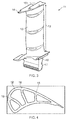
- FIG 3 illustrates an exemplary turbine blade of a type which may be scanned via the method of the present invention.
- the blade 11 comprises an elongate aerofoil section 12 having a span 13.
- the blade comprises a shroud 14 which may have one or more tip fins 15.
- a platform 16 and a root portion 17 are defined at the opposite end of the aerofoil section 12 for use in attaching the blade 11 to the rotor of a turbine.
- the aerofoil section 12 is generally of primary interest when CT scanning turbine blades, and in particular the internal structure of the aerofoil section 12.
- Figure 4 illustrates an exemplary CT image taken as a transverse slice, orthogonal to the span 13, through the aerofoil section 12 of a blade 11.
- the internal structure of the aerofoil section is generally hollow and comprises a series of reinforcing webs 18.
- the support 19 which, as will be described in more detail below, is configured to receive and support a plurality of blades 11 of the general type described above.
- the support 19 comprises a generally planar platform 20, and is configured to be rotatable about an axis of rotation 21 which is orthogonal to the platform 20.
- a plurality of upwardly open sockets 22 are fixed to the platform 20, and are arranged in an equi-spaced array around the axis of rotation 21.
- the positions of the sockets 22 are thus rotationally symmetrical about the axis 21.
- the sockets 22 are each configured to receive a respective turbine blade 11, as will be described below, and in the particular arrangement illustrated there are three such sockets such that the rotatable support 19 is configured to receive and support three turbine blades 11.
- the rotatable support 19 also includes an elongate identification element 23 in the form of a pillar mounted to the platform 20 so as to be upstanding therefrom and which is arranged such that its longitudinal axis is substantially coincident with the axis of rotation 21 of the support 19. Adjacent the identification element 23, there is provided a shorter datum element 24 which is also elongate in form and is mounted to the platform 20 so to be upstanding therefrom. The datum element is arranged such that its longitudinal axis is substantially parallel to the axis of rotation 21 of the support 19. Further details of the identification element 23 and the datum element 24, and their respective functions in the method of the present invention, will be described hereinbelow.
- the turbine blades 11 are mounted to the rotatable support 19 such that the spans of their respective aerofoil sections 12 are substantially parallel to the axis of rotation 21 of the support 19. This is achieved by securely fitting a support clamp 25 to the root portion 17 of each blade 11, as illustrated in figure 6 .
- each clamp 25 is securely engaged around the root portion 17 of a respective blade 11 at a position spaced below the platform 16, and hence in spaced relation to the aerofoil section 12, of the blade 11.
- Each clamp 25 has an elongate mounting pin 26 which is sized and configured to be received within a respective mounting socket 22 on the rotatable support 19, whereupon the socket 22 is tightened around the pin 26 to engage the pin tightly, thereby fixing the blade in position on the support 19.
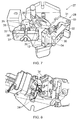
- Figure 7 illustrates part of an ancillary alignment tool 27 which is used to orientate and properly align the blades 11 relative to one another and the rotatable support 19 when they are each engaged with their respective sockets 22.
- the alignment tool 27 includes a pair of clamps 28, 29, each of which is configured to clampingly engage part of the aerofoil section 12 of each blade 11 in turn.
- Figure 7 shows the blade 12 absent its mounting clamp 25 for the sake of clarity.
- One of the two clamps 28 of the alignment tool 27 is configured to engage the aerofoil section 12 of the blade around the trailing edge 30 of the aerofoil section, and comprises a pair of clamp members 31, 32 which are pivotally connected to one another at 33.
- the clamping members 31, 32 of the clamp 28 are tightly closed around the trailing edge 30 of the aerofoil section 12, such that electrodes 34 (shown most clearly in figure 8 which shows the clamp 28 in an open configuration) on the clamping members 31, 32 engage and make contact with the surface of the aerofoil section 12.
- the other clamp 29 of the alignment tool 27 is configured to engage the aerofoil section 12 of the blade 11 around its leading edge 35, and also comprises a pair of clamp members 36, 37 which are pivotally connected to one another at 38.
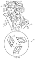
- the clamping members 36, 37 of the clamp 29 are tightly closed around the leading edge 35 of the aerofoil section 12, such that electrodes 39 (shown most clearly in figure 9 which shows the clamp 29 in an open configuration) on the clamping members 36, 37 engage and make contact with the surface of the aerofoil section 12.
- the electrodes 34, 39 on the two clamps 28, 29 of the alignment tool 27 are connected to a display panel 40 which is shown in 10 and comprises a graphical representation 41 of the blade 11.
- the display panel has a series of lights 42 or other indicia, each of which corresponds to a respective electrode 34, 39 and which is illuminated when the respective electrode makes contact with the surface of the blade's aerofoil section 12.
- the display panel 40 may also include an additional indicator light 43, or other indicia, which becomes illuminated when both of the clamps 28, 29 of the alignment tool 27 are tightly closed and all of the electrodes 34, 39 are in contact with the surface of the aerofoil section, thereby providing convenient visual confirmation of proper engagement of the tool 27 with the blade 11.
- the above-described tool arrangement comprising clamps 28, 29 and electrodes 24, 39 is configured to engage the aerofoil section of each blade in turn in a very precise and repeatable manner, thereby ensuring accurate orientation of the tool relative to the blade 11.
- the alignment tool 27 is shown engaged with a turbine blade 11 in the manner described above. Also shown is a mounting clamp 25 engaged with the root portion 17 of the blade 11, at a position below the aerofoil section 12 of the blade and thus also below the alignment tool 27.
- the alignment tool 27 may be mounted to, and controlled by, a three-axis manipulator arrangement 44 which may then be used to move the alignment tool 27 so as to position the mounting pin 26 of the mounting clamp 25 affixed to the blade 11 above a respective mounting socket 22 on the rotatable support 19.
- the mounting pin 26 is then lowered into the socket to a predetermined depth, and the alignment tool 27 is carefully manipulated to position the blade 11 accurately relative to the rotational support 29, both in terms of its height above the platform 20 and in terms of its rotational position relative to the socket 22.
- the socket 22 is tightened around the mounting pin 26, and the alignment tool 27 is then removed from the blade 11 to leave the blade mounted in position on the rotatable support with the span 13 of its aerofoil section 12 lying parallel to the rotational axis 21 of the support 19.
- the alignment tool 27 can then be engaged with another blade 11 and used to align and mount the next blade to the support 19. The process is repeated until a respective blade 11 is mounted to each mounting socket 22.
- Figure 12 is a schematic plan view, from above, showing three turbine blades 11 mounted to the rotatable support 19 in a favoured orientation relative to one another and to the support 19.
- the blades 11 are mounted in equi-spaced relationship to one another so as to form an array around the axis of rotation 21 of the support 19.
- the span 13 of each blade's aerofoil section 12 is substantially parallel to the axis of rotation 21. Because the blades 11 are preferably identical to one another, the resulting array of blades is thus rotationally symmetrical about the axis of rotation 21.
- the support 20 will be rotated about its axis 21 such that the array of blades 11 will rotate as a whole around the axis 21 within the x-ray beam 6, in the manner described above with reference to figure 1 .
- a plurality of blades 11 can be CT scanned simultaneously such that a plurality of slices can be taken through the aerofoil sections 12 of all of the blades 11 together.
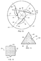
- Figure 13 is a transverse cross-sectional representation through the aerofoil sections 12 of the array of blades 11 mounted to the rotatable support 19 in a preferred arrangement.
- the above-described use of the alignment tool 27 is intended to ensure accurate positioning of the blades 11 in this orientation.
- the blades 11 shown in an arrangement in which their leading edges 35 are proximal to the axis of rotation 21 and their trailing edges 30 are distal to the axis of rotation 21.
- the reverse orientation could be employed such that the blades' trailing edges 30 would be proximal to the axis of rotation 21 and their leading edges 35 would be distal to the axis of rotation.
- the blades 11 will be arranged such that the chord line 45 of each aerofoil section 12 will make a tangent to a notional circle 46 centred on the axis of rotation 21.
- this notional circle 46 should be as small as possible of the reasons already mentioned above. Nevertheless, in order to prevent overlap of the aerofoil sections 12 of respective blades within the x-ray beam 6, it is proposed that the blades 11 will all be arranged, both in terms of number and their radial position from the axis of rotation 21, such that no notional line 47 can be constructed orthogonal to the axis of rotation (i.e. in the plane of figure 13 ) which would intersect the aerofoil section 12 of more than one blade 11. A number of such notional lines 47 are shown in figure 13 in phantom, and it will be noted that all intersect only the aerofoil section 12 of a single blade 11. It is proposed that the blades 11 will be located as closely as possible to the rotational axis 21 whilst still preserving this characteristic.
- the above-described positioning requirements of the blades 11 can most conveniently be achieved when the total number of blades 11 in the array around the axis of rotation 21 is an odd number.
- the overall diameter of the resulting array can be minimized and so three is presently considered to represent the optimum number of blades 11.
- a number of discrete arrays of blades with the above-described properties could be arranged in spaced-apart relation along the axis of rotation 21, (for example by providing the support 19 with a plurality of spaced apart platforms 19 with associated mounting sockets 22) thereby permitting a larger number of blades 11 to be mounted onto the rotatable support 19 at a time without adversely affecting the CT scanning performance of the arrangement.
- the resulting images taken as slices through the aerofoil sections 12 of the blades 11 will feature all of the blades 11 in the array supported by the rotatable support 19. It is therefore important to provide a way to identify individual blades 11 within the array, both in the resulting CT images and also visually on the rotatable support 19. This is the function of the identification pillar 23.
- the identification pillar 23 is elongate and arranged such that its longitudinal axis is substantially coincident with the rotational axis 21 of the rotatable support 19. Accordingly, it will be noted that the identification pillar 23 is located within the array of blades 11 such that the blades 11 are distributed around the identification pillar 23.
- Figure 14 illustrates a transverse cross-sectional view taken through the identification pillar 23 at a height above the platform 20 of the rotatable support which corresponds to a position through the aerofoil sections 12 of the blades 11.
- the illustrated pillar 23 has a triangular shape in cross-section and thus has three straight side edges 48, each of which of course corresponds to a respective planar side face of the pillar. It is proposed that the pillar 23 will be oriented such that each side 48 will be arranged in facing relation to a respective blade 11 mounted to the rotatable support 19 in the manner described above.
- one of the side edges 48 of the pillar 23 is entirely straight, but the other two are provided with respective peripheral edge features 49, 50 which are thus also directed towards respective blades 11 mounted to the rotatable support 19.
- the edge features 49, 50 are both provided in the form of recesses, but each has a different form.
- one of the edge features 49 is provided in the form of a single square-sectioned recessed groove extending up at least part of the axial length of the pillar 23, whilst the other edge feature 50 is provided in the form of two spaced-apart square-sectioned recessed grooves extending up at least part of the axial length of the pillar 23.
- the edge feature 49 appears as a single square recess
- the other edge feature 50 appears as a pair of square recesses.
- the identification pillar will be made from a material which is considerably less dense than the material from which the turbine blades 11 are made, so that the pillar 23 will not absorb as much x-ray energy as the blades 11 during the CT scanning process, thereby ensuring that the CT output obtained will still have good resolution properties. Nevertheless, it is important that the transverse cross-sectional shape of the pillar 23 will feature in the CT output so that it the different shape configurations of each of its faces can be used to facilitate identification of individual said blades in the CT output. It is therefore currently proposed that the pillar 23 will be formed from a resin or polymeric material.
- peripheral edge features 49, 50 being configured to appear in the CT output images
- the features 49, 50 will also be visible by the naked eye on the exterior of the identification pillar 23, so that the individual blades 11 in the array mounted to the rotatable support 19 can be identified by the features as they are mounted to the support 19, and both during and after the CT scanning process.
- Figure 15 illustrates a transverse cross-sectional view taken through another form of identification pillar 23.
- the pillar 23 has a square cross-section rather than a triangular one as in the arrangement shown in figure 14 .
- the pillar 23 shown in figure 15 is thus configured to be used to identify individual blades 11 provided in an array of four such blades arranged around the pillar 23, such that each side edge of the square cross-sectional shape, and thus each planar side face of the pillar 23, is directed towards a respective said blade 11.
- the pillar 23 illustrated in figures 15 has peripheral edge features 51, 52, 53 (along all except one of its side edges) which are each provided in the form of a projection.
- the projections may be provided in the form out outwardly projecting ribs provided along at least part of the axial length of the pillar 23.
- Each projection 51, 52, 53 is configured so as to have a different cross-sectional shape, and so the arrangement illustrated in figure 15 includes a projection 51 of triangular configuration in cross-section, a projection 52 of semi-circular configuration in cross-section, and a projection 53 of square configuration in cross-section.
- Each side of the pillar 23 thus has an edge profile which is visually different from the other sides.
- the pillar 23 illustrated in figures 16 to 19 can be considered to be similar in many respects to the triangular sectioned pillar 23 illustrated in figures 5 and 14 and described above.
- one side 48 of the pillar is provided without any edge feature
- another side 48 is provided with an edge feature 49 in the form of a single square-sectioned recessed groove 54
- another side 48 is provided with an edge feature 50 in the form of two spaced-apart square-sectioned recessed grooves 55.
- the two spaced-apart grooves 55 are not parallel to one another along the length of the pillar 23, but are instead arranged such that they converge towards one another with increasing distance along the axis of the pillar 23 above the rotatable support 19. This is illustrated most clearly in figure 16 , where the converging relationship of the two grooves 55 is shown as viewed from the side of the pillar 23.
- the relative spacing between the grooves 55 as viewed in transverse cross-section through the pillar 23, and thus in the CT slices taken through the pillar 23 and the blades 11 during the scanning process can be used to determine the axial position of each CT slice through the blades 11.
- figure 17 denotes the cross-sectional shape of the pillar at a first axial position 56 indicated in figure 16 , and are the grooves 55 are thus relatively close to one another.
- Figure 18 denotes the cross-sectional shape of the pillar 23 at a second axial position 57, which is lower than the first position 56 and so the grooves 55 can be seen to be spaced further apart at this position.
- Figure 19 denotes the cross-sectional shape of the pillar 23 at a third axial position 58, which is lower than the second position 57, and so the grooves 55 can be seen to be spaced even further apart at this position.
- this characteristic of the pillar 23 can be embodied in projecting ribs instead of grooves.
- the datum element 24 is intended to be used to determine a datum height above the platform 20 of the rotatable support 19. Accordingly, the datum element 24 is configured to have a planar end surface 59 which is oriented so as to be substantially orthogonal to the axis of rotation 21 of the rotatable support, and which is spaced above the platform 20 of the rotatable support 19 by a predetermined distance.
- the datum element 24 is preferably made from machinable material having a density which is generally comparable to that of the turbine blades 11 to be inspected. It is therefore proposed that the datum element may be formed from tool steel.
- the predetermined height at which the end surface 59 of the datum element is spaced above the platform 20 is preferably set such that it is below the aerofoil sections 12 of the blades 11 which are of most interest, and so the datum element will not appear in CT slices which are taken through the aerofoil sections 12. Nevertheless, the datum element 24 can be used to determine the vertical height above the platform 20 for a datum CT slice which can be captured initially and which can then be used as a reference to accurately determine the vertical height of subsequent CT slices which may then be taken through the aerofoil sections 12 at predetermined offset distances from the datum slice.
- the datum CT slice will be taken at a position along the axis of rotation 21, and thus above the platform 20, such that the end surface 59 of the datum element 24 appears in the resulting output image.
Landscapes
- Health & Medical Sciences (AREA)
- Engineering & Computer Science (AREA)
- Nuclear Medicine, Radiotherapy & Molecular Imaging (AREA)
- Pulmonology (AREA)
- Radiology & Medical Imaging (AREA)
- Theoretical Computer Science (AREA)
- Physics & Mathematics (AREA)
- Life Sciences & Earth Sciences (AREA)
- Chemical & Material Sciences (AREA)
- Analytical Chemistry (AREA)
- Biochemistry (AREA)
- General Health & Medical Sciences (AREA)
- General Physics & Mathematics (AREA)
- Immunology (AREA)
- Pathology (AREA)
- Apparatus For Radiation Diagnosis (AREA)
- Analysing Materials By The Use Of Radiation (AREA)
Applications Claiming Priority (1)
| Application Number | Priority Date | Filing Date | Title |
|---|---|---|---|
| GBGB1508065.8A GB201508065D0 (en) | 2015-05-12 | 2015-05-12 | A method of scanning Aerofoil blades |
Publications (1)
| Publication Number | Publication Date |
|---|---|
| EP3096132A1 true EP3096132A1 (de) | 2016-11-23 |
Family
ID=53489472
Family Applications (1)
| Application Number | Title | Priority Date | Filing Date |
|---|---|---|---|
| EP16168887.4A Withdrawn EP3096132A1 (de) | 2015-05-12 | 2016-05-10 | Vorrichtung zum abtasten von turbinenschaufeln |
Country Status (3)
| Country | Link |
|---|---|
| US (1) | US10416097B2 (de) |
| EP (1) | EP3096132A1 (de) |
| GB (1) | GB201508065D0 (de) |
Cited By (1)
| Publication number | Priority date | Publication date | Assignee | Title |
|---|---|---|---|---|
| EP4425157A1 (de) * | 2023-03-03 | 2024-09-04 | Rolls-Royce plc | Verfahren zum abtasten eines objekts in einer abtastvorrichtung |
Families Citing this family (6)
| Publication number | Priority date | Publication date | Assignee | Title |
|---|---|---|---|---|
| CN107076684B (zh) | 2014-09-02 | 2021-04-02 | 株式会社尼康 | 测量处理装置、测量处理方法和测量处理程序 |
| JP6763301B2 (ja) | 2014-09-02 | 2020-09-30 | 株式会社ニコン | 検査装置、検査方法、検査処理プログラムおよび構造物の製造方法 |
| GB202300064D0 (en) * | 2023-01-04 | 2023-02-15 | Rolls Royce Plc | A method for scanning of an object in a scanning apparatus |
| GB202300063D0 (en) * | 2023-01-04 | 2023-02-15 | Rolls Royce Plc | A method for scanning of objects in a scanning apparatus |
| GB202300062D0 (en) * | 2023-01-04 | 2023-02-15 | Rolls Royce Plc | A method for scanning of an object in a scanning apparatus |
| CN119438259B (zh) * | 2024-10-15 | 2025-10-24 | 中国直升机设计研究所 | 一种无轴承旋翼柔性梁全三维ct检测方法 |
Citations (2)
| Publication number | Priority date | Publication date | Assignee | Title |
|---|---|---|---|---|
| CN101435784A (zh) * | 2008-10-14 | 2009-05-20 | 重庆大学 | 涡轮叶片ct检测装置及其检测方法 |
| EP2587450A1 (de) * | 2011-10-27 | 2013-05-01 | Nordson Corporation | Verfahren und Vorrichtung zur Erzeugung eines dreidimensionalen Modells eines Bereichs von Interesse mithilfe eines Bildgebungssystems |
Family Cites Families (27)
| Publication number | Priority date | Publication date | Assignee | Title |
|---|---|---|---|---|
| US4803639A (en) * | 1986-02-25 | 1989-02-07 | General Electric Company | X-ray inspection system |
| US4989225A (en) * | 1988-08-18 | 1991-01-29 | Bio-Imaging Research, Inc. | Cat scanner with simultaneous translation and rotation of objects |
| CA1301371C (en) * | 1988-08-23 | 1992-05-19 | Jan Erik Aune | Log scanner |
| US5119408A (en) * | 1990-10-31 | 1992-06-02 | General Electric Company | Rotate/rotate method and apparatus for computed tomography x-ray inspection of large objects |
| JP2978238B2 (ja) * | 1990-11-29 | 1999-11-15 | 株式会社日立製作所 | Ct装置 |
| US5319693A (en) * | 1992-12-30 | 1994-06-07 | General Electric Company | Three dimensional computerized tomography scanning configuration for imaging large objects with smaller area detectors |
| US5635728A (en) * | 1995-06-19 | 1997-06-03 | Denoptix, Inc. | Rotating scanner system for reading multiple storage layer radiation screens |
| US6658089B1 (en) * | 2002-07-11 | 2003-12-02 | General Electric Company | System and method for image identification and quality indication for radiographic inspection |
| US6888924B2 (en) * | 2003-06-25 | 2005-05-03 | General Electric Company | Method, apparatus, and medium for calibration of tomosynthesis system geometry using fiducial markers with non-determined position |
| US7623624B2 (en) * | 2005-11-22 | 2009-11-24 | Illumina, Inc. | Method and apparatus for labeling using optical identification elements characterized by X-ray diffraction |
| EP1935342B1 (de) * | 2006-12-19 | 2015-02-25 | Brainlab AG | Artefakt-Eliminierung für eine medizintechnische Beckenregistrierung mit getrackter, systembekannter Beckenstütze |
| US8208711B2 (en) * | 2007-09-07 | 2012-06-26 | General Electric Company | Method for automatic identification of defects in turbine engine blades |
| US7876875B2 (en) * | 2008-04-09 | 2011-01-25 | United Technologies Corp. | Computed tomography systems and related methods involving multi-target inspection |
| GB0901040D0 (en) * | 2009-01-22 | 2009-03-11 | Renishaw Plc | Optical measuring method and system |
| US20100194749A1 (en) * | 2009-01-30 | 2010-08-05 | Gerald Bernard Nightingale | Systems and methods for non-destructive examination of an engine |
| WO2010108112A1 (en) * | 2009-03-20 | 2010-09-23 | Proto Manufacturing Ltd. | Non-destructive testing systems and methods |
| US20110299653A1 (en) * | 2010-12-15 | 2011-12-08 | General Electric Company | Method and apparatus for laminography inspection |
| MX2011001035A (es) * | 2011-01-27 | 2012-07-27 | Mexicano Inst Petrol | Procedimiento para determinar la porosidad efectiva y total de rocas sedimentarias carbonatadas, y caracterizacion morfologica de sus micro nanoporos. |
| US8861673B2 (en) * | 2011-11-30 | 2014-10-14 | United Technologies Corporation | Component aperture location using computed tomography |
| US8750561B2 (en) * | 2012-02-29 | 2014-06-10 | United Technologies Corporation | Method of detecting material in a part |
| JP5807967B2 (ja) * | 2012-10-11 | 2015-11-10 | 株式会社リガク | X線分析装置 |
| WO2014147045A1 (de) * | 2013-03-19 | 2014-09-25 | Carl Zeiss Microscopy Gmbh | Verfahren zur erzeugung von bilddaten eines objekts und teilchenstrahlgerät zur durchführung dieses verfahrens |
| US9410905B2 (en) * | 2013-03-27 | 2016-08-09 | United Technologies Corporation | Non-destructive inspection of an article using cross-sections through internal feature |
| US9945796B2 (en) * | 2013-10-15 | 2018-04-17 | Shimadzu Corporation | X-ray fluorescence analysis method and X-ray fluorescence analysis system |
| GB2520711B (en) * | 2013-11-28 | 2018-06-20 | Nikon Metrology Nv | Calibration apparatus and method for computed tomography |
| CN107111302A (zh) * | 2014-12-17 | 2017-08-29 | 沙特基础工业全球技术有限公司 | 鉴别用于增材制造的材料的特性 |
| US10746671B2 (en) * | 2015-03-06 | 2020-08-18 | Ge Sensing & Inspection Technologies Gmbh | Imaging system and method with scatter correction |
-
2015
- 2015-05-12 GB GBGB1508065.8A patent/GB201508065D0/en not_active Ceased
-
2016
- 2016-05-10 US US15/150,883 patent/US10416097B2/en not_active Expired - Fee Related
- 2016-05-10 EP EP16168887.4A patent/EP3096132A1/de not_active Withdrawn
Patent Citations (2)
| Publication number | Priority date | Publication date | Assignee | Title |
|---|---|---|---|---|
| CN101435784A (zh) * | 2008-10-14 | 2009-05-20 | 重庆大学 | 涡轮叶片ct检测装置及其检测方法 |
| EP2587450A1 (de) * | 2011-10-27 | 2013-05-01 | Nordson Corporation | Verfahren und Vorrichtung zur Erzeugung eines dreidimensionalen Modells eines Bereichs von Interesse mithilfe eines Bildgebungssystems |
Cited By (2)
| Publication number | Priority date | Publication date | Assignee | Title |
|---|---|---|---|---|
| EP4425157A1 (de) * | 2023-03-03 | 2024-09-04 | Rolls-Royce plc | Verfahren zum abtasten eines objekts in einer abtastvorrichtung |
| US12584870B2 (en) | 2023-03-03 | 2026-03-24 | Rolls-Royce Plc | Method for scanning of an object in a scanning apparatus |
Also Published As
| Publication number | Publication date |
|---|---|
| US10416097B2 (en) | 2019-09-17 |
| GB201508065D0 (en) | 2015-06-24 |
| US20160334345A1 (en) | 2016-11-17 |
Similar Documents
| Publication | Publication Date | Title |
|---|---|---|
| US10416097B2 (en) | Method of scanning aerofoil blades | |
| US10416096B2 (en) | Method of scanning aerofoil blades | |
| US6678346B2 (en) | Cone-beam CT scanner with image reconstruction using multiple sub-images | |
| US4908782A (en) | Airfoil inspection method | |
| US20160073064A1 (en) | Apparatus and a method of inspecting a turbomachine | |
| JPH11108859A (ja) | 複合層構造の計算機式断層写真検査方法 | |
| EP3786630A1 (de) | Abtastvorrichtung | |
| CH698184B1 (de) | Verfahren zur Inspektion der Schwalbenschwanzverbindungszapfen von einem Turbinenrad oder einer Turbinenschaufel auf Risse. | |
| JP2000504262A (ja) | 円及び線のコーン・ビーム断層写真法システムを用いた縦方向に無限界の物体の正確な領域再構成 | |
| US20080253510A1 (en) | Computed Tomography System and Method | |
| US10996180B2 (en) | Method for non-destructive testing of a turbomachine part | |
| CN108463689A (zh) | 用于对涡轮机,尤其是飞行器涡轮机或喷气发动机,的叶片进行非接触式三维检测的装置 | |
| US10598608B2 (en) | Method of inspecting interior of wind turbine blade and inspection device for wind turbine blade | |
| EP2846155B1 (de) | Prüfvorrichtung und Verfahren zum Prüfen eines Gegenstandes | |
| CN109788951B (zh) | 用于利用校正制造自固位缝合线的方法和设备 | |
| US20200271440A1 (en) | Shape Measuring Device for Hose Connector Fitting, Shape Measuring Method for Hose Connector Fitting and Shape Measuring Program for Hose Connector Fitting | |
| EP4397965A1 (de) | Verfahren zum abtasten eines objekts in einer abtastvorrichtung | |
| US9410905B2 (en) | Non-destructive inspection of an article using cross-sections through internal feature | |
| EP4397966B1 (de) | Verfahren und system zum abtasten von turbinenschaufeln in einer abtastvorrichtung | |
| EP2261597A1 (de) | Verfahren und Vorrichtung zur Erkennung der dreidimensionalen Struktur eines Baumstammes | |
| CN113155964A (zh) | 一种在役风机主轴端面超声检测探头定位装置 | |
| EP2846156A1 (de) | Verfahren zur Inspektion eines Artikels | |
| CN111024004B (zh) | 一种电动剃须刀刀头网罩内侧平面度测量装置和方法 | |
| KR20090041654A (ko) | 엑스 레이 씨티 촬영 장치에서 중심축 이동에 기인된배율을 보정하는 방법 | |
| US20250173849A1 (en) | Tomographic analysis method |
Legal Events
| Date | Code | Title | Description |
|---|---|---|---|
| PUAI | Public reference made under article 153(3) epc to a published international application that has entered the european phase |
Free format text: ORIGINAL CODE: 0009012 |
|
| AK | Designated contracting states |
Kind code of ref document: A1 Designated state(s): AL AT BE BG CH CY CZ DE DK EE ES FI FR GB GR HR HU IE IS IT LI LT LU LV MC MK MT NL NO PL PT RO RS SE SI SK SM TR |
|
| AX | Request for extension of the european patent |
Extension state: BA ME |
|
| STAA | Information on the status of an ep patent application or granted ep patent |
Free format text: STATUS: REQUEST FOR EXAMINATION WAS MADE |
|
| 17P | Request for examination filed |
Effective date: 20170523 |
|
| RBV | Designated contracting states (corrected) |
Designated state(s): AL AT BE BG CH CY CZ DE DK EE ES FI FR GB GR HR HU IE IS IT LI LT LU LV MC MK MT NL NO PL PT RO RS SE SI SK SM TR |
|
| RAP1 | Party data changed (applicant data changed or rights of an application transferred) |
Owner name: ROLLS-ROYCE PLC |
|
| STAA | Information on the status of an ep patent application or granted ep patent |
Free format text: STATUS: THE APPLICATION IS DEEMED TO BE WITHDRAWN |
|
| 18D | Application deemed to be withdrawn |
Effective date: 20201201 |