EP3096435A1 - Systeme d'alimentation electrique sans coupure avec capacite de correction de defaut - Google Patents
Systeme d'alimentation electrique sans coupure avec capacite de correction de defaut Download PDFInfo
- Publication number
- EP3096435A1 EP3096435A1 EP16166047.7A EP16166047A EP3096435A1 EP 3096435 A1 EP3096435 A1 EP 3096435A1 EP 16166047 A EP16166047 A EP 16166047A EP 3096435 A1 EP3096435 A1 EP 3096435A1
- Authority
- EP
- European Patent Office
- Prior art keywords
- power supply
- power
- source
- output line
- supply system
- Prior art date
- Legal status (The legal status is an assumption and is not a legal conclusion. Google has not performed a legal analysis and makes no representation as to the accuracy of the status listed.)
- Granted
Links
Images







Classifications
-
- H—ELECTRICITY
- H02—GENERATION; CONVERSION OR DISTRIBUTION OF ELECTRIC POWER
- H02J—ELECTRIC POWER NETWORKS; CIRCUIT ARRANGEMENTS OR SYSTEMS FOR SUPPLYING OR DISTRIBUTING ELECTRIC POWER; SYSTEMS FOR STORING ELECTRIC ENERGY
- H02J9/00—Circuit arrangements for emergency or stand-by power supply, e.g. for emergency lighting
- H02J9/04—Circuit arrangements for emergency or stand-by power supply, e.g. for emergency lighting in which the distribution system is disconnected from the normal source and connected to a standby source
- H02J9/06—Circuit arrangements for emergency or stand-by power supply, e.g. for emergency lighting in which the distribution system is disconnected from the normal source and connected to a standby source with automatic change-over, e.g. UPS systems
- H02J9/061—Circuit arrangements for emergency or stand-by power supply, e.g. for emergency lighting in which the distribution system is disconnected from the normal source and connected to a standby source with automatic change-over, e.g. UPS systems for DC powered loads
-
- H—ELECTRICITY
- H02—GENERATION; CONVERSION OR DISTRIBUTION OF ELECTRIC POWER
- H02J—ELECTRIC POWER NETWORKS; CIRCUIT ARRANGEMENTS OR SYSTEMS FOR SUPPLYING OR DISTRIBUTING ELECTRIC POWER; SYSTEMS FOR STORING ELECTRIC ENERGY
- H02J9/00—Circuit arrangements for emergency or stand-by power supply, e.g. for emergency lighting
- H02J9/04—Circuit arrangements for emergency or stand-by power supply, e.g. for emergency lighting in which the distribution system is disconnected from the normal source and connected to a standby source
- H02J9/06—Circuit arrangements for emergency or stand-by power supply, e.g. for emergency lighting in which the distribution system is disconnected from the normal source and connected to a standby source with automatic change-over, e.g. UPS systems
-
- H—ELECTRICITY
- H02—GENERATION; CONVERSION OR DISTRIBUTION OF ELECTRIC POWER
- H02M—APPARATUS FOR CONVERSION BETWEEN AC AND AC, BETWEEN AC AND DC, OR BETWEEN DC AND DC, AND FOR USE WITH MAINS OR SIMILAR POWER SUPPLY SYSTEMS; CONVERSION OF DC OR AC INPUT POWER INTO SURGE OUTPUT POWER; CONTROL OR REGULATION THEREOF
- H02M3/00—Conversion of DC power input into DC power output
- H02M3/02—Conversion of DC power input into DC power output without intermediate conversion into AC
- H02M3/04—Conversion of DC power input into DC power output without intermediate conversion into AC by static converters
-
- H—ELECTRICITY
- H02—GENERATION; CONVERSION OR DISTRIBUTION OF ELECTRIC POWER
- H02M—APPARATUS FOR CONVERSION BETWEEN AC AND AC, BETWEEN AC AND DC, OR BETWEEN DC AND DC, AND FOR USE WITH MAINS OR SIMILAR POWER SUPPLY SYSTEMS; CONVERSION OF DC OR AC INPUT POWER INTO SURGE OUTPUT POWER; CONTROL OR REGULATION THEREOF
- H02M7/00—Conversion of AC power input into DC power output; Conversion of DC power input into AC power output
- H02M7/02—Conversion of AC power input into DC power output without possibility of reversal
- H02M7/04—Conversion of AC power input into DC power output without possibility of reversal by static converters
-
- H—ELECTRICITY
- H02—GENERATION; CONVERSION OR DISTRIBUTION OF ELECTRIC POWER
- H02M—APPARATUS FOR CONVERSION BETWEEN AC AND AC, BETWEEN AC AND DC, OR BETWEEN DC AND DC, AND FOR USE WITH MAINS OR SIMILAR POWER SUPPLY SYSTEMS; CONVERSION OF DC OR AC INPUT POWER INTO SURGE OUTPUT POWER; CONTROL OR REGULATION THEREOF
- H02M7/00—Conversion of AC power input into DC power output; Conversion of DC power input into AC power output
- H02M7/42—Conversion of DC power input into AC power output without possibility of reversal
- H02M7/44—Conversion of DC power input into AC power output without possibility of reversal by static converters
Definitions
- the present invention relates to the technical field of uninterruptable power supply system. More particularly, the invention relates to the field of converters for providing DC power to a DC load. Still more particularly, the invention refers to the area of fault clearance for UPS systems providing DC power to a DC load.
- UPS uninterruptable power supply
- the converters are responsible for converting source power into output power as required for a load.
- the converters are typically connected to a primary power source for normal operation and a secondary power source, which powers the load in case of a failure of the primary power source.
- Primary and secondary source can be any kind of source, which can be provided individually for each converter, or which can be provided commonly for groups of converters or even all converters.
- the primary power source is an AC source
- the secondary power source is a DC source.
- the typical design of a converter comprises a DC link, which is connected to a first and second input converter unit connected to the primary and secondary power source, respectively, and an output converter unit, which provides the output power as required for the load.
- the design of the UPS system comprises AC/DC and DC/AC converters for historical reasons due to the simplicity and prevalence of AC power transmission. Nevertheless, the output converter unit can be a DC/AC-converter or a DC/DC-converter, depending on the type of load.
- An AC/DC-DC/AC conversion scheme with an AC load is industry standard but suffers from a penalty of not optimal system efficiency as typical loads comprise AC/DC- DC/DC converters. Accordingly, the DC/AC conversion at the load side of the converter prior to the AC/DC conversion at an input side of the load is not necessary and merely adds losses to the overall system efficiency.
- Fault clear capability refers to clearance of operating conditions of the load.
- the load side of the converter is current limited due to availability of practical semiconductor devices allowing a maximum current.
- abnormal operating conditions of the load e.g. a short circuit
- Protection means of the UPS system can be activated prior to activating protection means at the load side, thereby leaving the load in a potentially dangerous state for the load and for operating personal.
- UPS systems which provide AC power to the load
- abnormal operating conditions e.g. a short circuit
- a separate power path bypassing the converter units to connect the AC source directly to the load side to clear the fault through a current, which is limited only by source impedance.
- the present invention provides an uninterruptable power supply system comprising a first AC source providing three-phase AC power via a four-wire AC-power supply line, a DC source providing DC power via a DC power supply line, and a power converter receiving AC power from the first AC source and/or DC power from the DC source and delivering two wire DC power to a load via a DC output line, whereby one pole of the DC output line is connected to the neutral reference of the four-wire AC-power supply line, whereby the uninterruptable power supply system further comprises a bypass device for passing power from its output side to the DC output line, whereby the bypass device and the power converter are connected in parallel to the DC output line, and the bypass device comprises at least one switching unit, which receives AC power at its input side, and a control unit, whereby the switching unit is controlled by the control unit to supply pulsed power from an AC power supply with essentially the same polarity as the DC output line.
- the present invention also provides a method for realizing a bypass in an uninterruptable power supply system comprising a first AC source providing three-phase AC power via a four-wire AC-power supply line a DC source providing DC power via a DC power supply line, and a power converter receiving AC power from the first AC source and/or DC power from the DC source and delivering DC power to a load via a DC output line, whereby one pole of the DC output line is connected to the neutral reference of the four-wire AC-power supply line, comprising the steps of providing a bypass device, connecting the bypass device and the power converter in parallel to the DC output line, whereby the bypass device comprises at least one switching unit, detecting a load failure, controlling the switching unit to supply pulsed power from an AC power supply received from its input side with essentially the same polarity as the DC output line for passing power from its output side to the DC output line.
- the basic idea of the invention is to provide power pulses from the AC source to the load directly without passing the converter. Accordingly, current limitations given for the converter can be overridden and fault clear capability is fully enabled.
- the pulsed power refers to power from power pulses having a desired polarity, e.g. a positive or negative voltage, as provided from the AC source.
- the switching unit enables current supply to the load, which is in case of a short circuit at the load merely limited by the source impedance, so that protection mechanisms of the load can operate in a desired manner. This way, increased system and operator safety is secured.
- Controlling the switching unit to supply pulsed power from an AC power supply received from its input side to the load refers e.g. to switching the switching device on or conductive, so that a bypass from the AC source to the load is provided, and switching off refers to switching the switching device not conductive, so that the bypass from the AC source to the load is interrupted.
- the two wire DC power typically comprises a reference and a positive or negative voltage, which is provided from the power converter. Nevertheless, the converter is not limited to providing only positive or negative power. Nevertheless, each load receives two-wire DC power with positive or negative voltage, in particular with respect to the neutral reference.
- the two wire DC power comprises a reference and a positive or negative voltage, which is provided from the power converter, and each load receives two-wire DC power with positive or negative voltage, in particular with respect to the neutral reference.
- the load is connected to two poles of the DC output line. Nevertheless, the load can also be connected to the positive and negative voltage of the DC output line.
- the control unit can be part of the converter, i.e. the converter and the bypass device have a common control unit.
- the bypass device is provided integral with the converter, it is beneficial to provide only one control unit controlling the bypass device and the converter units of the converter function. Nevertheless, the converter and the bypass device can have individual control units.
- the DC output line comprises three poles including a positive pole, a negative pole, and a an electric middle pole, whereby the electric middle pole is connected to the neutral reference of the four-wire AC-power supply line.
- the two wire DC power is provided to the positive and the negative pole with the additional neutral reference.
- the bypass device comprises at least two switching units, which are connected to the positive and negative pole, for supplying pulsed power with essentially the same polarity as the DC output line to the load at the positive and negative pole with reference to the electric middle pole.
- a bypass can be provided for loads connected to the positive or negative pole of the DC output line in the same way.
- the bypass device comprises at least two switching units for supplying pulsed power with essentially the same polarity as the DC output line to the load, whereby the switching units are at their input side connected to different phases of the first AC source which are connected at their output side to the same pole of the DC output line.
- the bypass device comprises three switching units, i.e. one switching unit per phase of the AC source.
- the switching units comprise a silicon controlled half wave rectifier circuit or at least one IGBT.
- the silicon controlled half wave rectifier enables a simple means for providing a bypass for the converter units of the converter, which provides current to enable fault clear operation.
- Typical semiconductor components for use in the silicon controlled half wave rectifier are power transistors.
- the IGBT is capable of uni-directional conduction only, which provides a very simple means for implementing a switching unit for current conduction in only one direction. Typically, the IGBT connected in series with a diode.
- the uninterruptable power supply system further comprises a second AC source, which is connected to the bypass device, and the bypass device is controlled by the control unit to supply pulsed power from the second AC source.
- the second AC source can power the load via the at least one switching unit independently from the first AC source. Accordingly, fault clear capability can be provided with high reliability.
- control unit is adapted to perform a control of the at least one switching unit based on a phase angle of the AC source.
- a phase angle of the AC source i.e. a positive or a negative voltage
- the uninterruptable power supply system comprises multiple converters, which are connected in parallel between the first AC source and the DC source on the one side and the DC output line on the other side.
- the implementation of the UPS system with multiple parallel converters has many advantages. Amongst others, some of the advantages of a system design with multiple parallel converters are scalability of the UPS system for varying loads and redundancy of converters in case of failure. Furthermore, depending on the actual load, converters which are not required can be operated in standby or even shut down to reduce energy consumption of the UPS system.
- the first AC source and the DC source can be provided independently as sources for the entire UPS system, i.e. as a global sources.
- multiple first AC sources and DC sources can be provided for powering the converters individually, or for powering groups of converters.
- the uninterruptable power supply system comprises a bypass input protection device connected at the power supply side of the bypass device.
- the bypass input protection device can be any suitable kind of protection device.
- a simple protection device is a thermal fuse. Since the current through the bypass is merely limited by the impedance of the load, the current through the bypass device may in the case of a fault at the load reach very high values, so that the protection device may avoid harm to the UPS system.
- the uninterruptable power supply system comprises a converter input protection device connected between the first AC source and the converter.
- the converter input protection device can be any suitable kind of protection device.
- a simple converter input protection device is a thermal fuse. The converter input protection device limits the input current of the converter to avoid damages of the converter.
- the input wiring and protection from the source to the bypass device and the converter can be differently implemented.
- a protection device can be provided independently for the bypass device and the converter in the respective connection to the AC source.
- the bypass device and the converter can have a common protection device.
- the bypass device and the converter can have a common main protection device and an additional protection device in the connection of the bypass device, i.e. a bypass input protection device.
- bypass input protection device is provided to activate its protection with less energy than the converter input protection device. Since the bypass device is only activated in case of failure at the load side to enable fault clear capability, energy through the bypass device is typically small.
- the bypass device comprises a discharge switch unit, which is connected between one pole of the DC output line, which is not connected to the neutral reference of the of the four-wire AC-power supply line, and a current sink, and the control unit is adapted to connect the pole to the current sink after the switching unit is switched on.
- the discharge switch unit enables uni-directional conduction between the pole and the current sink. This enables to clamp overvoltages due to bypass currents when a load side fault is cleared.
- the pole can be connected to the current sink almost simultaneously when switching is performed or after the switching event.
- the current sink can be neutral reference of the of the four-wire AC-power supply line or a system reference.
- FIG. 1 shows a typical setup of an uninterruptable power supply (UPS) system 100 according to a first, preferred embodiment.
- the UPS system 100 comprises multiple parallel converters 102, which are connected in parallel between a power supply side 104 and a load side 106 of the UPS system 100.
- the UPS system 100 comprises a first AC source 108 as primary source and a DC source 110 as secondary source, which are connected via an AC power bus 112 and a DC power bus 114, respectively, to the converters 102 in parallel.
- the first AC source 108 provides three-phase AC power
- the AC power bus 112 is a four-wire AC-power supply line, which is connected to the three phases L1, L2, L3 of the first AC source 108 and neutral of the first AC source 108.
- the converters 102 can be connected to one or multiple phases L1, L2, L3.
- the figures usually show the AC power bus 112 as a single line, which comprises the three phases L1, L2, L3, whereby the converter 102 is connected to one or multiple phases L1, L2, L3.
- the DC power bus 114 is also referred to as DC power supply line.
- multiple first AC sources 108 and/or multiple DC sources 110 are connected to the AC power bus 112 and a DC power bus 114, respectively.
- one pole of the DC output line 116 is connected to the neutral reference of the four-wire AC-power supply line 112.
- the UPS system 100 is connected via the output power line 116 to a load 118.
- the load 118 is a two-phase load 118 receiving two wire DC power.
- the two wire DC power comprises a reference and a positive or negative voltage, which is provided from the power converter.
- each load 116 receives two-wire DC power with positive or negative voltage, in particular with respect to the neutral reference.
- the load 118 is connected to two poles of the DC output line 116.
- the converters 102 are connected via communication bus 120 to a control device 122.
- the communication bus 120 is shown on the load side 106, it is to be noted that the communication bus 120 is independent from the load side 106 or the power supply side 104.
- Each converter 102 can be individually activated, de-activated or set in any mode of operation by the control device 122 upon respective communication via the communication bus 120.
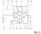
- Each converter 102 in this embodiment has an identical setup, which can be seen in Fig. 2 with respect to a second embodiment. Nevertheless, in alternative embodiments, the converters 102 may be provided with different properties.
- the UPS system 100 of the second embodiment can be used as shown in Fig. 2 with a single converter 102.
- a typical UPS system 100 according to the second embodiment comprises multiple power converters 102, also referred to as converters, which are not shown in Fig. 2 .
- the UPS system 100 of the second embodiment is in-line with the UPS system 100 of the first embodiment.
- Features not explicitly described with respect to the second embodiment are identical to those of the first embodiment.
- each converter 102 comprises a DC link 130, which is connected at the power supply side 104 to a first and second input converter unit 132, 134.
- the first and second input converter units 132, 134 are connected via AC power bus 112 and DC power bus 114 to the AC source 108 and the DC source 110, respectively.
- the first input converter unit 132 is a AC/DC converter unit
- the second input converter unit 134 is a DC/DC converter unit.
- the DC link 130 is connected via output power bus 116 to an output converter unit 136, which provides the DC output power to the load 118.
- Each converter further comprises a control unit 138 for controlling the operation of the converter units 132, 134, 136, and which receives commands from the control device 122 via communication bus 120.
- the control unit 138 can be seen e.g. in Fig. 3 and is connected to the communication bus 120 shown in Fig. 1 .
- the control unit 138 controls the converter units 132, 134, 136 to receive AC power from the first AC source 108 and/or from the DC source 110 and to deliver two wire DC power to the load 118 via the DC output line 116.
- the UPS system comprises an additional device 140 comprising a bypass unit 142, which enables a bypass of the converter units 132, 134, 136 and the DC link 130 in case of load failure.
- the bypass unit 142 is activated by the control unit 138 in an overload or fault clear situation exceeding the converter 102 current source capability, e.g. to achieve fuse blow at the load side.
- the bypass unit 142 is connected to the output power bus 116 and the AC source 108.
- the bypass unit 142 is connected to a second AC source 150, as indicated in Fig. 12 with respect to the eleventh embodiment.
- Fig. 3 refers to a bypass formed with the bypass device 142 between the first AC source and the load 118 in accordance with a fourth embodiment.
- Two parallel implementations of the bypass device 142 are indicated by the parallel connections between the first AC source 108 and the load 118.
- an IGBT and a diode are provided in series.
- the IGBT is the switching unit 144.
- only a thyristor is used as switching unit 144.
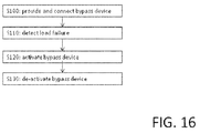
- the function of the UPS system 100 of the second embodiment is essentially identical. The function is described with respect to Fig. 4 and 5 . The method for realizing the bypass is shown in Fig. 16 .
- step S100 the bypass device 142 is provided and connected between the power supply side 104 and the load side 106.
- step S110 a load failure is detected at time T1.
- a short circuit occurs at the load 118, so that load voltage drops to almost zero and the current starts to increase.
- the detection is done either by the control device 122 or the control unit 138.
- step S120 the bypass device 142 is activated.
- the switching unit 144 is switched on by the control unit 138 via the gating circuit 146 to supply pulsed power from the first AC power supply 108 with the same polarity as the DC output line 116 for passing power to the load 118.
- the three phases L1, L2, L3 of the AC-power supply line 112 alternate from positive to negative voltage polarity and back.
- L2 is connected via bypass device 142 to the DC output line 116 to increase the current and to enable fault clearance.
- the run of the current with the increase at T2 is shown in Fig. 5 .
- protection means of the load 118 can be activated, which can be seen at T3.
- L2 can be gated again until the protection means of the load 118 are activated.
- multiple power pulses are provided from L2 in this case, whereby power from L2 of the first AC source 108 is only provided to the DC output line 116 when the polarity of L2 and the DC output line 116 are the same.
- control unit 138 is adapted to perform a control of the switching unit 144 based on a phase angle of the first AC source 108. Hence, only part of the half wave of L2 having the polarity of the DC output line 116 is provided from the bypass device 142 to the load 118.
- step S130 the bypass device 142 is de-activated.
- the fault is cleared at the load 118 and the converter 102 returns to normal operation to provide DC power to the DC output line 116.
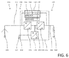
- a UPS system 100 according to a third embodiment is shown in Fig. 6 .
- the UPS system 100 of the third embodiment is in-line with the UPS system 100 of the second embodiment, as described with respect to Fig. 2 .
- Features not explicitly described with respect to the third embodiment are identical to those of the second embodiment.
- the bypass device 142 is provided as integral part of the converter 102.
- the bypass device 142 comprises a switching unit 144, which is a semiconductor switch in this embodiment, in particular a thyristor, and a gating circuit 146, which together provide a rectifier.
- the behavior of the UPS system 100 of the third embodiment is identical to the behavior of the UPS system 100 of the second embodiment, as described above in detail.
- a UPS system 100 according to a fourth embodiment is shown in Fig. 7 .
- the UPS system 100 of the fourth embodiment is in-line with the UPS system 100 of the second or third embodiment, as described above.
- Features not explicitly described with respect to the fourth embodiment are identical to those of the second or third embodiment.
- the bypass device 142 is provided as integral part of the converter 102.
- the bypass device 142 comprises three switching units 144 and three gating circuits 146, which are connected to the three phases L1, L2, L3 of the first AC power source 108. Accordingly, power pulses from the three phases L1, L2, L3 can provide power to the DC output line 116 in case of failure, e.g. in case of a short circuit.
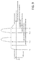
- This function can be seen in Figs. 8 and 9 . For reasons of simplicity, only positive half wave of L1 and L2 is shown in Fig. 8 .
- bypass device 142 The general behavior of the bypass device 142 is as described above with respect to the second embodiment. The difference is that all phases L1, L2, L3 can support the load 118 via the DC output line 116. Accordingly, after the fault occurs at T1, at time T2.1, L1 is connected via bypass device 142 to the DC output line 116 to increase the current and to enable fault clearance. The run of the current with the increase at T2.1 is shown in Fig. 9 . When the polarity of L1 turns negative, the switching unit 144 of L1 disconnects L1. At time T2.2, L2 is connected via bypass device 142 to the DC output line 116 as described above with respect to L1.
- protection means of the load 118 can be activated, which can be seen at T3.
- multiple power pulses are provided from L1 and L2 in this case in accordance with the polarity of L1 and L2, respectively, and the DC output line 116.
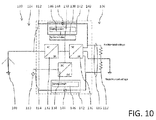
- a UPS system 100 according to a fifth embodiment is shown in Fig. 10 .
- the UPS system 100 of the fifth embodiment is in-line with the UPS system 100 of the previous embodiments described above.
- Features not explicitly described with respect to the fifth embodiment are identical to those of the previous embodiments.
- the DC output line 116 comprises three poles including a positive pole, a negative pole, and a an electric middle pole, whereby the electric middle pole is connected to the neutral reference of the four-wire AC-power supply line 112.
- the bypass device 142 is provided as integral part of the converter 102.
- the bypass device 142 comprises two switching units 144 and two gating circuits 146.
- the two switching units 144 are connected to the positive and negative pole of the DC output line 116 for supplying pulsed power with essentially the same polarity as the DC output line 116 to the load 118 at the positive and negative pole with reference to the electric middle pole.
- the two switching units 144 can be connected to the same phase L1, L2, L2, or to different phases L1, L2, L2.
- multiple switching units 144 and gating circuits 146 can be provided accordance with the fourth embodiment for connecting each pole of the DC output line 116 to multiple phases L1, L2, L3 subsequently.
- bypass device 142 although depicted as two individual devices can be implemented commonly as a single device.
- the general behavior of the bypass device 142 of the fifth embodiment is as described above with respect to the second or third embodiment.
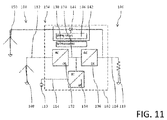
- a UPS system 100 according to a sixth embodiment is shown in Fig. 11 .
- the UPS system 100 of the sixth embodiment is in-line with the UPS system 100 of the previous embodiments described above.
- Features not explicitly described with respect to the sixth embodiment are identical to those of the previous embodiments.
- the UPS system 100 of the sixth embodiment comprises a second AC source 150, which is connected to the bypass device 142, and the bypass device 142 is controlled by the control unit 138 to supply pulsed power from the second AC source 150.
- the general behavior of the bypass device 142 of the sixth embodiment is as described above with respect to the second or third embodiment.
- a UPS system 100 according to a seventh embodiment is shown in Fig. 12 .
- the UPS system 100 of the seventh embodiment is in-line with the UPS system 100 of the previous embodiments described above.
- Features not explicitly described with respect to the seventh embodiment are identical to those of the previous embodiments.
- the UPS system 100 of the seventh embodiment comprises a discharge switch unit 152, which is connected between one pole of the DC output line 116, which is not connected to the neutral reference of the of the four-wire AC-power supply line 112, and a current sink 154.
- the current sink 154 is neutral reference of the of the four-wire AC-power supply line 112 in this embodiment.
- the control unit 138 is adapted to control the discharge switch unit 152 to connect the pole to the current sink 154 after the switching unit 144 is switched on, i.e. after the switching unit 144 of the bypass device 142 de-activates the bypass.
- the discharge switch unit 152 can be switch to connect the pole to the current sink 154 almost simultaneously when switching of the bypass devices 142 is performed, or after switching the switching of the bypass devices 142.
- the discharge switch unit 152 comprises a discharge switch element 156 and a discharge gating circuit 158 similar to the bypass device 142.
- the discharge switch unit 152 enables uni-directional conduction between the pole and the current sink 154 to clamp overvoltages due to bypass currents when a load side fault is cleared.
- bypass device 142 of the seventh embodiment is as described above with respect to the second or third embodiment.
- a UPS system 100 according to an eighth embodiment is shown in Fig. 13 .
- the UPS system 100 of the eighth embodiment is in-line with the UPS system 100 of the previous embodiments described above.
- Features not explicitly described with respect to the eighth embodiment are identical to those of the previous embodiments.
- the UPS system 100 according to the eighth embodiment is based on the UPS system 100 of the third embodiment.
- the UPS system 100 of the eighth embodiment comprises a backfeed protection switch 160 and a converter input protection device 162, which is a thermal fuse in this embodiment.
- the converter input protection device 162 is provided in the AC power supply line 112 prior to branches connecting the first converter unit 132 and the bypass device 142 and protects the converter 102 and the converter 102 entirely.
- UPS system 100 and the bypass device 142 of the eighth embodiment is as described above with respect to the second or third embodiment.
- a UPS system 100 according to a ninth embodiment is shown in Fig. 14 .
- the UPS system 100 of the ninth embodiment is in-line with the UPS system 100 of the previous embodiments described above.
- Features not explicitly described with respect to the ninth embodiment are identical to those of the previous embodiments.
- the UPS system 100 according to a ninth embodiment is identical to the UPS system 100 according to the eighth with an additional bypass input protection device 164, which is a thermal fuse in this embodiment, and which is provided in a branch connecting the converter input protection device 162 and the backfeed protection switch 160.
- an additional bypass input protection device 164 which is a thermal fuse in this embodiment, and which is provided in a branch connecting the converter input protection device 162 and the backfeed protection switch 160.
- UPS system 100 and the bypass device 142 of the ninth embodiment is as described above with respect to the second or third embodiment.
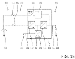
- a UPS system 100 according to a tenth embodiment is shown in Fig. 15 .
- the UPS system 100 of the tenth embodiment is in-line with the UPS system 100 of the previous embodiments described above.
- Features not explicitly described with respect to the tenth embodiment are identical to those of the previous embodiments.
- the UPS system 100 according to a tenth embodiment is identical to the UPS system 100 according to the ninth with the difference, that the bypass input protection device 164 and the converter input protection device 162 are connected in parallel directly to the AC power supply line 112.
- UPS system 100 and the bypass device 142 of the tenth embodiment is as described above with respect to the second or third embodiment.
Landscapes
- Engineering & Computer Science (AREA)
- Power Engineering (AREA)
- Business, Economics & Management (AREA)
- Emergency Management (AREA)
- Inverter Devices (AREA)
- Dc-Dc Converters (AREA)
- Rectifiers (AREA)
Priority Applications (1)
| Application Number | Priority Date | Filing Date | Title |
|---|---|---|---|
| EP16166047.7A EP3096435B1 (fr) | 2015-05-18 | 2016-04-19 | Systeme d'alimentation electrique sans coupure avec capacite de correction de defaut |
Applications Claiming Priority (2)
| Application Number | Priority Date | Filing Date | Title |
|---|---|---|---|
| EP15167954 | 2015-05-18 | ||
| EP16166047.7A EP3096435B1 (fr) | 2015-05-18 | 2016-04-19 | Systeme d'alimentation electrique sans coupure avec capacite de correction de defaut |
Publications (2)
| Publication Number | Publication Date |
|---|---|
| EP3096435A1 true EP3096435A1 (fr) | 2016-11-23 |
| EP3096435B1 EP3096435B1 (fr) | 2018-04-18 |
Family
ID=53180587
Family Applications (1)
| Application Number | Title | Priority Date | Filing Date |
|---|---|---|---|
| EP16166047.7A Active EP3096435B1 (fr) | 2015-05-18 | 2016-04-19 | Systeme d'alimentation electrique sans coupure avec capacite de correction de defaut |
Country Status (4)
| Country | Link |
|---|---|
| US (1) | US9985470B2 (fr) |
| EP (1) | EP3096435B1 (fr) |
| JP (1) | JP6732533B2 (fr) |
| CN (1) | CN106169804B (fr) |
Cited By (3)
| Publication number | Priority date | Publication date | Assignee | Title |
|---|---|---|---|---|
| WO2020147109A1 (fr) * | 2019-01-18 | 2020-07-23 | Abb Schweiz Ag | Convertisseur de puissance pv |
| CN113508555A (zh) * | 2019-03-13 | 2021-10-15 | 思科技术公司 | 网络通信系统中的多相位脉冲电力 |
| CN114301156A (zh) * | 2021-11-29 | 2022-04-08 | 科华数据股份有限公司 | 电源及电源系统 |
Families Citing this family (7)
| Publication number | Priority date | Publication date | Assignee | Title |
|---|---|---|---|---|
| ES2883718T3 (es) * | 2016-11-09 | 2021-12-09 | Abb Schweiz Ag | SAI multifase de 3 hilos con derivación |
| US11223208B2 (en) * | 2017-08-21 | 2022-01-11 | General Electric Company | Method and system for controlling integration of DC power source in hybrid power generation system |
| CN108808838B (zh) * | 2018-06-21 | 2021-09-07 | 常熟市国瑞科技股份有限公司 | 高频隔离舰用交流电源的多功率模块协调控制方法 |
| EP3772154A1 (fr) * | 2019-07-31 | 2021-02-03 | ABB Schweiz AG | Un système d'alimentation électrique et une alimentation électrique sans coupure comprenant le système d'alimentation électrique |
| EP3820010A1 (fr) * | 2019-11-07 | 2021-05-12 | ABB Schweiz AG | Ensemble d'alimentation électrique avec compensation d'énergie réactive |
| US11888340B2 (en) * | 2020-12-04 | 2024-01-30 | Schneider Electric It Corporation | Method to enhance the life of a lithium battery |
| KR20250167610A (ko) * | 2024-02-28 | 2025-12-01 | 가부시키가이샤 티마이크 | 무정전 전원 장치 및 급전 시스템 |
Citations (4)
| Publication number | Priority date | Publication date | Assignee | Title |
|---|---|---|---|---|
| US20080265680A1 (en) * | 2007-04-27 | 2008-10-30 | Liebert Corporation | Method for pulse width modulation synchronization in a parallel ups system |
| US20120119581A1 (en) * | 2010-11-12 | 2012-05-17 | Kristian Silberbauer | Static bypass switch with built in transfer switch capabilities |
| US20140097690A1 (en) * | 2012-09-14 | 2014-04-10 | Chloride Srl | Uninterruptible Power Supply System With Fast Transfer For Undervoltage Source Line Failures |
| WO2014053464A1 (fr) * | 2012-10-04 | 2014-04-10 | Borri S.P.A. | Conversion électrique à haut rendement et système de gestion de la continuité pour des systèmes d'alimentation sans coupure (ups) et appareils connexes |
Family Cites Families (11)
| Publication number | Priority date | Publication date | Assignee | Title |
|---|---|---|---|---|
| KR100668118B1 (ko) * | 2005-12-30 | 2007-01-16 | 한국전기연구원 | 권선형 유도 발전기 제어용 전력변환장치 및 전력변환방법 |
| DE102006050289B4 (de) * | 2006-10-23 | 2015-11-12 | Rittal Gmbh & Co. Kg | Leistungsversorgungseinrichtung |
| US8183714B2 (en) * | 2007-12-12 | 2012-05-22 | Mcdonnell Alan | Electric power distribution methods and apparatus |
| CN201374570Y (zh) * | 2008-12-29 | 2009-12-30 | 北京中创瑞普科技有限公司 | 具有开机自检功能的ups |
| IT1397013B1 (it) * | 2009-11-03 | 2012-12-20 | Trevi Energy S P A | Sistema di controllo di centrali eoliche con aerogeneratori equipaggiati con convertitori modulari a corrente continua. |
| CN201805271U (zh) * | 2010-04-03 | 2011-04-20 | 联正电子(深圳)有限公司 | 一种不间断电源装置 |
| EP2795758B1 (fr) * | 2011-12-21 | 2017-07-19 | ABB Schweiz AG | Dispositif pour commander la transmission de puissance dans un système de transmission électrique a courant continu haute tension |
| US9804622B2 (en) * | 2012-01-05 | 2017-10-31 | Schneider Electric It Corporation | Calibration of current sensors in parallel power converters |
| CN202840667U (zh) * | 2012-08-27 | 2013-03-27 | 青岛经济技术开发区创统科技发展有限公司 | 无扰动切换的不间断电源 |
| EP2907220B8 (fr) * | 2012-10-11 | 2018-04-18 | Schneider Electric IT Corporation | Circuit et méthode pour procurer une alimentation électrique sans coupure. |
| CA2927718C (fr) * | 2013-03-15 | 2016-12-13 | Bakercorp | Production de signaux electriques cc pour un reacteur electrochimique |
-
2016
- 2016-04-19 EP EP16166047.7A patent/EP3096435B1/fr active Active
- 2016-05-17 JP JP2016098610A patent/JP6732533B2/ja active Active
- 2016-05-17 US US15/157,226 patent/US9985470B2/en active Active
- 2016-05-18 CN CN201610328592.9A patent/CN106169804B/zh active Active
Patent Citations (4)
| Publication number | Priority date | Publication date | Assignee | Title |
|---|---|---|---|---|
| US20080265680A1 (en) * | 2007-04-27 | 2008-10-30 | Liebert Corporation | Method for pulse width modulation synchronization in a parallel ups system |
| US20120119581A1 (en) * | 2010-11-12 | 2012-05-17 | Kristian Silberbauer | Static bypass switch with built in transfer switch capabilities |
| US20140097690A1 (en) * | 2012-09-14 | 2014-04-10 | Chloride Srl | Uninterruptible Power Supply System With Fast Transfer For Undervoltage Source Line Failures |
| WO2014053464A1 (fr) * | 2012-10-04 | 2014-04-10 | Borri S.P.A. | Conversion électrique à haut rendement et système de gestion de la continuité pour des systèmes d'alimentation sans coupure (ups) et appareils connexes |
Non-Patent Citations (1)
| Title |
|---|
| SITHIMOLADA V ET AL: "Facility-level DC vs. typical ac distribution for data centers: A comparative reliability study", TENCON 2010 - 2010 IEEE REGION 10 CONFERENCE, IEEE, PISCATAWAY, NJ, USA, 21 November 2010 (2010-11-21), pages 2102 - 2107, XP031898433, ISBN: 978-1-4244-6889-8, DOI: 10.1109/TENCON.2010.5686625 * |
Cited By (5)
| Publication number | Priority date | Publication date | Assignee | Title |
|---|---|---|---|---|
| WO2020147109A1 (fr) * | 2019-01-18 | 2020-07-23 | Abb Schweiz Ag | Convertisseur de puissance pv |
| CN113508555A (zh) * | 2019-03-13 | 2021-10-15 | 思科技术公司 | 网络通信系统中的多相位脉冲电力 |
| CN113508555B (zh) * | 2019-03-13 | 2024-05-24 | 思科技术公司 | 网络通信系统中的多相位脉冲电力 |
| US12126456B2 (en) | 2019-03-13 | 2024-10-22 | Cisco Technology, Inc. | Multiple phase pulse power in a network communications system |
| CN114301156A (zh) * | 2021-11-29 | 2022-04-08 | 科华数据股份有限公司 | 电源及电源系统 |
Also Published As
| Publication number | Publication date |
|---|---|
| JP6732533B2 (ja) | 2020-07-29 |
| US9985470B2 (en) | 2018-05-29 |
| CN106169804A (zh) | 2016-11-30 |
| JP2016220526A (ja) | 2016-12-22 |
| US20160344232A1 (en) | 2016-11-24 |
| CN106169804B (zh) | 2021-01-12 |
| EP3096435B1 (fr) | 2018-04-18 |
Similar Documents
| Publication | Publication Date | Title |
|---|---|---|
| EP3096435B1 (fr) | Systeme d'alimentation electrique sans coupure avec capacite de correction de defaut | |
| US8624437B2 (en) | Power conversion system and method | |
| KR101389579B1 (ko) | 전력용 컨버터 | |
| CN101297469B (zh) | 传输系统及其控制方法 | |
| US9780557B2 (en) | Electrical apparatus | |
| US20180076727A1 (en) | Converter arrangement and method for short-circuit protection thereof | |
| CN101512865B (zh) | 电力传输系统和用于控制电力传输系统中电力流动的方法 | |
| EP3289654B1 (fr) | Système de transmission d'énergie en courant continu bipolaire | |
| EP3032677B1 (fr) | Réseau électrique à courant continu | |
| EP3051646B1 (fr) | Système d'alimentation en courant continu | |
| US20190334340A1 (en) | Hybrid dc circuit breaker | |
| CN104701969A (zh) | 不间断电源和不间断电源系统 | |
| CA2903362A1 (fr) | Dispositif de conversion de puissance | |
| US11695269B2 (en) | Electrical AC/DC conversion arrangement | |
| US12266489B2 (en) | Electrical network | |
| KR102465166B1 (ko) | 선박 발전 장치 및 선박 전력 분배 시스템 | |
| EP4507147B1 (fr) | Système de protection de puissance | |
| JP6700578B2 (ja) | 無停電電源装置 | |
| CN111095766A (zh) | 驱动器组中的中间电路耦连 | |
| JP2005192354A (ja) | 交流スイッチ装置及びこれを使用した電力供給装置 | |
| US8553381B2 (en) | Gradually reducing resistive clamp | |
| JP7395417B2 (ja) | 遮断装置 | |
| CN117375198A (zh) | 一种快速自动转换开关电路及其控制方法 | |
| EP2939343A1 (fr) | Agencement interrupteur électrique et méthode d'accouplement d'une source d'énergie électrique avec une charge |
Legal Events
| Date | Code | Title | Description |
|---|---|---|---|
| PUAI | Public reference made under article 153(3) epc to a published international application that has entered the european phase |
Free format text: ORIGINAL CODE: 0009012 |
|
| AK | Designated contracting states |
Kind code of ref document: A1 Designated state(s): AL AT BE BG CH CY CZ DE DK EE ES FI FR GB GR HR HU IE IS IT LI LT LU LV MC MK MT NL NO PL PT RO RS SE SI SK SM TR |
|
| AX | Request for extension of the european patent |
Extension state: BA ME |
|
| RAP1 | Party data changed (applicant data changed or rights of an application transferred) |
Owner name: ABB SCHWEIZ AG |
|
| STAA | Information on the status of an ep patent application or granted ep patent |
Free format text: STATUS: REQUEST FOR EXAMINATION WAS MADE |
|
| 17P | Request for examination filed |
Effective date: 20170519 |
|
| RBV | Designated contracting states (corrected) |
Designated state(s): AL AT BE BG CH CY CZ DE DK EE ES FI FR GB GR HR HU IE IS IT LI LT LU LV MC MK MT NL NO PL PT RO RS SE SI SK SM TR |
|
| RIC1 | Information provided on ipc code assigned before grant |
Ipc: H02J 9/06 20060101AFI20170928BHEP Ipc: H02M 7/04 20060101ALI20170928BHEP |
|
| GRAP | Despatch of communication of intention to grant a patent |
Free format text: ORIGINAL CODE: EPIDOSNIGR1 |
|
| STAA | Information on the status of an ep patent application or granted ep patent |
Free format text: STATUS: GRANT OF PATENT IS INTENDED |
|
| INTG | Intention to grant announced |
Effective date: 20171106 |
|
| GRAS | Grant fee paid |
Free format text: ORIGINAL CODE: EPIDOSNIGR3 |
|
| GRAA | (expected) grant |
Free format text: ORIGINAL CODE: 0009210 |
|
| STAA | Information on the status of an ep patent application or granted ep patent |
Free format text: STATUS: THE PATENT HAS BEEN GRANTED |
|
| RIN1 | Information on inventor provided before grant (corrected) |
Inventor name: PAATERO, ESA-KAI |
|
| AK | Designated contracting states |
Kind code of ref document: B1 Designated state(s): AL AT BE BG CH CY CZ DE DK EE ES FI FR GB GR HR HU IE IS IT LI LT LU LV MC MK MT NL NO PL PT RO RS SE SI SK SM TR |
|
| REG | Reference to a national code |
Ref country code: GB Ref legal event code: FG4D |
|
| REG | Reference to a national code |
Ref country code: FR Ref legal event code: PLFP Year of fee payment: 3 |
|
| REG | Reference to a national code |
Ref country code: CH Ref legal event code: EP Ref country code: CH Ref legal event code: NV Representative=s name: ABB SCHWEIZ AG INTELLECTUAL PROPERTY (CH-LC/IP, CH |
|
| REG | Reference to a national code |
Ref country code: DE Ref legal event code: R096 Ref document number: 602016002475 Country of ref document: DE |
|
| REG | Reference to a national code |
Ref country code: AT Ref legal event code: REF Ref document number: 991461 Country of ref document: AT Kind code of ref document: T Effective date: 20180515 |
|
| REG | Reference to a national code |
Ref country code: IE Ref legal event code: FG4D |
|
| REG | Reference to a national code |
Ref country code: DE Ref legal event code: R082 Ref document number: 602016002475 Country of ref document: DE Representative=s name: VOGEL, ALBRECHT, DIPL.-ING. DR.-ING., DE |
|
| REG | Reference to a national code |
Ref country code: NL Ref legal event code: MP Effective date: 20180418 |
|
| REG | Reference to a national code |
Ref country code: LT Ref legal event code: MG4D |
|
| PG25 | Lapsed in a contracting state [announced via postgrant information from national office to epo] |
Ref country code: NL Free format text: LAPSE BECAUSE OF FAILURE TO SUBMIT A TRANSLATION OF THE DESCRIPTION OR TO PAY THE FEE WITHIN THE PRESCRIBED TIME-LIMIT Effective date: 20180418 |
|
| PG25 | Lapsed in a contracting state [announced via postgrant information from national office to epo] |
Ref country code: ES Free format text: LAPSE BECAUSE OF FAILURE TO SUBMIT A TRANSLATION OF THE DESCRIPTION OR TO PAY THE FEE WITHIN THE PRESCRIBED TIME-LIMIT Effective date: 20180418 Ref country code: AL Free format text: LAPSE BECAUSE OF FAILURE TO SUBMIT A TRANSLATION OF THE DESCRIPTION OR TO PAY THE FEE WITHIN THE PRESCRIBED TIME-LIMIT Effective date: 20180418 Ref country code: SE Free format text: LAPSE BECAUSE OF FAILURE TO SUBMIT A TRANSLATION OF THE DESCRIPTION OR TO PAY THE FEE WITHIN THE PRESCRIBED TIME-LIMIT Effective date: 20180418 Ref country code: LT Free format text: LAPSE BECAUSE OF FAILURE TO SUBMIT A TRANSLATION OF THE DESCRIPTION OR TO PAY THE FEE WITHIN THE PRESCRIBED TIME-LIMIT Effective date: 20180418 Ref country code: PL Free format text: LAPSE BECAUSE OF FAILURE TO SUBMIT A TRANSLATION OF THE DESCRIPTION OR TO PAY THE FEE WITHIN THE PRESCRIBED TIME-LIMIT Effective date: 20180418 Ref country code: BG Free format text: LAPSE BECAUSE OF FAILURE TO SUBMIT A TRANSLATION OF THE DESCRIPTION OR TO PAY THE FEE WITHIN THE PRESCRIBED TIME-LIMIT Effective date: 20180718 Ref country code: FI Free format text: LAPSE BECAUSE OF FAILURE TO SUBMIT A TRANSLATION OF THE DESCRIPTION OR TO PAY THE FEE WITHIN THE PRESCRIBED TIME-LIMIT Effective date: 20180418 Ref country code: NO Free format text: LAPSE BECAUSE OF FAILURE TO SUBMIT A TRANSLATION OF THE DESCRIPTION OR TO PAY THE FEE WITHIN THE PRESCRIBED TIME-LIMIT Effective date: 20180718 |
|
| PG25 | Lapsed in a contracting state [announced via postgrant information from national office to epo] |
Ref country code: LV Free format text: LAPSE BECAUSE OF FAILURE TO SUBMIT A TRANSLATION OF THE DESCRIPTION OR TO PAY THE FEE WITHIN THE PRESCRIBED TIME-LIMIT Effective date: 20180418 Ref country code: RS Free format text: LAPSE BECAUSE OF FAILURE TO SUBMIT A TRANSLATION OF THE DESCRIPTION OR TO PAY THE FEE WITHIN THE PRESCRIBED TIME-LIMIT Effective date: 20180418 Ref country code: GR Free format text: LAPSE BECAUSE OF FAILURE TO SUBMIT A TRANSLATION OF THE DESCRIPTION OR TO PAY THE FEE WITHIN THE PRESCRIBED TIME-LIMIT Effective date: 20180719 Ref country code: HR Free format text: LAPSE BECAUSE OF FAILURE TO SUBMIT A TRANSLATION OF THE DESCRIPTION OR TO PAY THE FEE WITHIN THE PRESCRIBED TIME-LIMIT Effective date: 20180418 |
|
| REG | Reference to a national code |
Ref country code: AT Ref legal event code: MK05 Ref document number: 991461 Country of ref document: AT Kind code of ref document: T Effective date: 20180418 |
|
| REG | Reference to a national code |
Ref country code: BE Ref legal event code: MM Effective date: 20180430 |
|
| PG25 | Lapsed in a contracting state [announced via postgrant information from national office to epo] |
Ref country code: PT Free format text: LAPSE BECAUSE OF FAILURE TO SUBMIT A TRANSLATION OF THE DESCRIPTION OR TO PAY THE FEE WITHIN THE PRESCRIBED TIME-LIMIT Effective date: 20180820 |
|
| REG | Reference to a national code |
Ref country code: DE Ref legal event code: R097 Ref document number: 602016002475 Country of ref document: DE |
|
| REG | Reference to a national code |
Ref country code: IE Ref legal event code: MM4A |
|
| PG25 | Lapsed in a contracting state [announced via postgrant information from national office to epo] |
Ref country code: MC Free format text: LAPSE BECAUSE OF FAILURE TO SUBMIT A TRANSLATION OF THE DESCRIPTION OR TO PAY THE FEE WITHIN THE PRESCRIBED TIME-LIMIT Effective date: 20180418 Ref country code: LU Free format text: LAPSE BECAUSE OF NON-PAYMENT OF DUE FEES Effective date: 20180419 Ref country code: SK Free format text: LAPSE BECAUSE OF FAILURE TO SUBMIT A TRANSLATION OF THE DESCRIPTION OR TO PAY THE FEE WITHIN THE PRESCRIBED TIME-LIMIT Effective date: 20180418 Ref country code: DK Free format text: LAPSE BECAUSE OF FAILURE TO SUBMIT A TRANSLATION OF THE DESCRIPTION OR TO PAY THE FEE WITHIN THE PRESCRIBED TIME-LIMIT Effective date: 20180418 Ref country code: EE Free format text: LAPSE BECAUSE OF FAILURE TO SUBMIT A TRANSLATION OF THE DESCRIPTION OR TO PAY THE FEE WITHIN THE PRESCRIBED TIME-LIMIT Effective date: 20180418 Ref country code: AT Free format text: LAPSE BECAUSE OF FAILURE TO SUBMIT A TRANSLATION OF THE DESCRIPTION OR TO PAY THE FEE WITHIN THE PRESCRIBED TIME-LIMIT Effective date: 20180418 Ref country code: RO Free format text: LAPSE BECAUSE OF FAILURE TO SUBMIT A TRANSLATION OF THE DESCRIPTION OR TO PAY THE FEE WITHIN THE PRESCRIBED TIME-LIMIT Effective date: 20180418 Ref country code: CZ Free format text: LAPSE BECAUSE OF FAILURE TO SUBMIT A TRANSLATION OF THE DESCRIPTION OR TO PAY THE FEE WITHIN THE PRESCRIBED TIME-LIMIT Effective date: 20180418 |
|
| PLBE | No opposition filed within time limit |
Free format text: ORIGINAL CODE: 0009261 |
|
| STAA | Information on the status of an ep patent application or granted ep patent |
Free format text: STATUS: NO OPPOSITION FILED WITHIN TIME LIMIT |
|
| PG25 | Lapsed in a contracting state [announced via postgrant information from national office to epo] |
Ref country code: IT Free format text: LAPSE BECAUSE OF FAILURE TO SUBMIT A TRANSLATION OF THE DESCRIPTION OR TO PAY THE FEE WITHIN THE PRESCRIBED TIME-LIMIT Effective date: 20180418 Ref country code: BE Free format text: LAPSE BECAUSE OF NON-PAYMENT OF DUE FEES Effective date: 20180430 Ref country code: SM Free format text: LAPSE BECAUSE OF FAILURE TO SUBMIT A TRANSLATION OF THE DESCRIPTION OR TO PAY THE FEE WITHIN THE PRESCRIBED TIME-LIMIT Effective date: 20180418 |
|
| 26N | No opposition filed |
Effective date: 20190121 |
|
| PG25 | Lapsed in a contracting state [announced via postgrant information from national office to epo] |
Ref country code: IE Free format text: LAPSE BECAUSE OF NON-PAYMENT OF DUE FEES Effective date: 20180419 |
|
| PG25 | Lapsed in a contracting state [announced via postgrant information from national office to epo] |
Ref country code: SI Free format text: LAPSE BECAUSE OF FAILURE TO SUBMIT A TRANSLATION OF THE DESCRIPTION OR TO PAY THE FEE WITHIN THE PRESCRIBED TIME-LIMIT Effective date: 20180418 |
|
| PG25 | Lapsed in a contracting state [announced via postgrant information from national office to epo] |
Ref country code: MT Free format text: LAPSE BECAUSE OF NON-PAYMENT OF DUE FEES Effective date: 20180419 |
|
| PG25 | Lapsed in a contracting state [announced via postgrant information from national office to epo] |
Ref country code: TR Free format text: LAPSE BECAUSE OF FAILURE TO SUBMIT A TRANSLATION OF THE DESCRIPTION OR TO PAY THE FEE WITHIN THE PRESCRIBED TIME-LIMIT Effective date: 20180418 |
|
| PG25 | Lapsed in a contracting state [announced via postgrant information from national office to epo] |
Ref country code: CY Free format text: LAPSE BECAUSE OF FAILURE TO SUBMIT A TRANSLATION OF THE DESCRIPTION OR TO PAY THE FEE WITHIN THE PRESCRIBED TIME-LIMIT Effective date: 20180418 Ref country code: MK Free format text: LAPSE BECAUSE OF NON-PAYMENT OF DUE FEES Effective date: 20180418 Ref country code: HU Free format text: LAPSE BECAUSE OF FAILURE TO SUBMIT A TRANSLATION OF THE DESCRIPTION OR TO PAY THE FEE WITHIN THE PRESCRIBED TIME-LIMIT; INVALID AB INITIO Effective date: 20160419 |
|
| PG25 | Lapsed in a contracting state [announced via postgrant information from national office to epo] |
Ref country code: IS Free format text: LAPSE BECAUSE OF FAILURE TO SUBMIT A TRANSLATION OF THE DESCRIPTION OR TO PAY THE FEE WITHIN THE PRESCRIBED TIME-LIMIT Effective date: 20180818 |
|
| REG | Reference to a national code |
Ref country code: CH Ref legal event code: U11 Free format text: ST27 STATUS EVENT CODE: U-0-0-U10-U11 (AS PROVIDED BY THE NATIONAL OFFICE) Effective date: 20260501 |
|
| PGFP | Annual fee paid to national office [announced via postgrant information from national office to epo] |
Ref country code: GB Payment date: 20260423 Year of fee payment: 11 |
|
| PGFP | Annual fee paid to national office [announced via postgrant information from national office to epo] |
Ref country code: DE Payment date: 20260422 Year of fee payment: 11 |
|
| PGFP | Annual fee paid to national office [announced via postgrant information from national office to epo] |
Ref country code: CH Payment date: 20260501 Year of fee payment: 11 |
|
| PGFP | Annual fee paid to national office [announced via postgrant information from national office to epo] |
Ref country code: FR Payment date: 20260420 Year of fee payment: 11 |