EP3096860B1 - Filtersystem mit kupplungsvorrichtung - Google Patents
Filtersystem mit kupplungsvorrichtung Download PDFInfo
- Publication number
- EP3096860B1 EP3096860B1 EP15703232.7A EP15703232A EP3096860B1 EP 3096860 B1 EP3096860 B1 EP 3096860B1 EP 15703232 A EP15703232 A EP 15703232A EP 3096860 B1 EP3096860 B1 EP 3096860B1
- Authority
- EP
- European Patent Office
- Prior art keywords
- filter system
- filter
- receptacle
- coupling device
- seal
- Prior art date
- Legal status (The legal status is an assumption and is not a legal conclusion. Google has not performed a legal analysis and makes no representation as to the accuracy of the status listed.)
- Active
Links
Images


Classifications
-
- B—PERFORMING OPERATIONS; TRANSPORTING
- B01—PHYSICAL OR CHEMICAL PROCESSES OR APPARATUS IN GENERAL
- B01D—SEPARATION
- B01D29/00—Filters with filtering elements stationary during filtration, e.g. pressure or suction filters, not covered by groups B01D24/00 - B01D27/00; Filtering elements therefor
- B01D29/96—Filters with filtering elements stationary during filtration, e.g. pressure or suction filters, not covered by groups B01D24/00 - B01D27/00; Filtering elements therefor in which the filtering elements are moved between filtering operations; Particular measures for removing or replacing the filtering elements; Transport systems for filters
-
- B—PERFORMING OPERATIONS; TRANSPORTING
- B01—PHYSICAL OR CHEMICAL PROCESSES OR APPARATUS IN GENERAL
- B01D—SEPARATION
- B01D35/00—Filtering devices having features not specifically covered by groups B01D24/00 - B01D33/00, or for applications not specifically covered by groups B01D24/00 - B01D33/00; Auxiliary devices for filtration; Filter housing constructions
- B01D35/30—Filter housing constructions
-
- B—PERFORMING OPERATIONS; TRANSPORTING
- B01—PHYSICAL OR CHEMICAL PROCESSES OR APPARATUS IN GENERAL
- B01D—SEPARATION
- B01D27/00—Cartridge filters of the throw-away type
- B01D27/08—Construction of the casing
-
- B—PERFORMING OPERATIONS; TRANSPORTING
- B01—PHYSICAL OR CHEMICAL PROCESSES OR APPARATUS IN GENERAL
- B01D—SEPARATION
- B01D35/00—Filtering devices having features not specifically covered by groups B01D24/00 - B01D33/00, or for applications not specifically covered by groups B01D24/00 - B01D33/00; Auxiliary devices for filtration; Filter housing constructions
- B01D35/005—Filters specially adapted for use in internal-combustion engine lubrication or fuel systems
-
- B—PERFORMING OPERATIONS; TRANSPORTING
- B01—PHYSICAL OR CHEMICAL PROCESSES OR APPARATUS IN GENERAL
- B01D—SEPARATION
- B01D2201/00—Details relating to filtering apparatus
- B01D2201/30—Filter housing constructions
- B01D2201/301—Details of removable closures, lids, caps, filter heads
- B01D2201/304—Seals or gaskets
-
- B—PERFORMING OPERATIONS; TRANSPORTING
- B01—PHYSICAL OR CHEMICAL PROCESSES OR APPARATUS IN GENERAL
- B01D—SEPARATION
- B01D2201/00—Details relating to filtering apparatus
- B01D2201/34—Seals or gaskets for filtering elements
- B01D2201/347—Radial sealings
-
- B—PERFORMING OPERATIONS; TRANSPORTING
- B01—PHYSICAL OR CHEMICAL PROCESSES OR APPARATUS IN GENERAL
- B01D—SEPARATION
- B01D2201/00—Details relating to filtering apparatus
- B01D2201/40—Special measures for connecting different parts of the filter
- B01D2201/4015—Bayonet connecting means
Definitions
- the invention relates to a filter system for filtering a fluid with a coupling device, in particular for use as a fuel filter of an internal combustion engine.
- Fuel filters commonly employ a disposable filter element that is replaced after predetermined time intervals of filter use.
- the disposable element is conventionally attached to the filter assembly base by a retaining or locking mechanism which is releasable to permit removal of the element for replacement purposes.
- a retaining or locking mechanism which is releasable to permit removal of the element for replacement purposes.
- the US 5302284 A describes a filter assembly that includes a base, a filter element attachable to the base, and a retaining collar for securing the filter element to the base.
- the collar holds an undulating spring that is held between spaced shoulders of the collar.
- the base part forms a receiving device for receiving the head of the filter element.
- a ramp and a detent, which is adjacent the end of the ramp, are arranged in front of the base.
- the retaining collar further includes a cam that has a pawl. The cam is engageable with the ramp so that when the collar is angularly rotated, the cam moves on the ramp and the pawl engages the detent under the bias of the spring to lock the filter element to the base.
- a filter device which has a replaceable filter which has a coaxial connection cylinder on the end face, on the outer surface of which there is a circumferential sealing groove for a radial seal and a coupling device. Both the sealing groove and the coupling device are formed by a common component.
- a circumferential spring element is disclosed which is supported on the one hand on the connecting cylinder and on the other hand on the filter head and pretensions a latching connection.
- the spring element is attached to the filter head side.
- EP 0 221 675 A2 discloses a separate design of the coupling element and seal, but not a separate seal holder. The seal is placed there directly in a beaded edge of the housing pot, while the coupling element is connected to the housing pot on the inner surface by (point) welds.
- a filter system in which a coupling device provides one or more coupling elements which can be introduced at least partially in an axial direction into a coupling contour arranged in a receptacle by a sliding / rotating movement, so as to to hold and lock the filter system in the holder in an end position.
- a filter system for filtering a fluid with an inlet and outlet on the front which comprises at least one filter element, a filter housing, a coupling device for coupling the filter system to a receptacle external to the filter system, and a seal holder with a seal for sealing the filter system on the receptacle.
- the coupling device provides one or more coupling elements, which can be inserted at least partially in an axial direction into a coupling contour arranged in the receptacle by a sliding / rotating movement in order to hold and lock the filter system in the receptacle in an end position.
- the coupling device is designed as a quick coupling.
- the filter system according to the invention can be attached with the coupling device, which is connected to a corresponding sealing arrangement, directly to a receptacle external to the filter system, which is seated, for example, on a die-cast head of an internal combustion engine.
- the filter system which can be arranged hanging, standing or lying down, is connected to the coupling device kept at the recording.
- the seal holder is connected to the coupling device.
- the coupling device can be designed in the form of a bayonet connection, so that the coupling elements, which are arranged on the coupling device, can slide into a coupling contour located on the receptacle when the filter system is screwed into the receptacle and can slide into an end position when the filter system is turned further , whereby the filter system is locked in the receptacle.
- This assembly procedure is supported by a tensioning element attached to the coupling device, e.g. in the form of a compression spring, which acts in the axial direction and, when the spring force of the tensioning element is overcome, allows the filter system to slide into the end position and then locks in this end position by the spring preload.
- the spring preload In order to unscrew the filter system, the spring preload must first be overcome again in order to then allow the coupling elements to slide out over the coupling contour and thus to be able to remove the filter system from the receptacle.
- the coupling device can expediently be made of a plastic, with thermoplastic materials that allow a maximum surface pressure of up to 20 N / mm 2 can be used for lower mechanical requirements, while thermosets can be used for higher mechanical requirements, which have a maximum surface pressure of up to 80 N / mm 2 allow. Since the coupling elements in particular are subject to higher loads when sliding in the coupling contour, duromers are a preferred embodiment. With these materials, the coupling elements can also be designed in any shape, which is advantageous for the structural design of the coupling device and the coupling contour.
- the receptacle can, for example, be made of die-cast aluminum, which has a higher strength than plastics, in particular a slightly higher strength than duromers, so that even when a filter system is attached and replaced several times, there are no signs of wear on the receptacle, which is part of the internal combustion engine can occur.
- the tensioning element for example in the form of a wave-shaped compression spring
- the structural shape of the receptacle is made simpler and the fastening of the tensioning element can also be made more flexible in the coupling device.
- the coupling device is made of plastic, additional lugs, for example, can be used as holding elements attached, which hold the clamping element and over which it could easily be inserted or even replaced.
- the coupling device can thus advantageously comprise a tensioning element which, in the assembled state, axially braces the filter system against the receptacle.
- a tensioning element which, in the assembled state, axially braces the filter system against the receptacle.
- the clamping element can expediently provide at least two, in particular for example five, elevations in the axial direction.
- the elevations apply the pretensioning force of the tensioning element; on the other hand, the elevations have the advantage that if one elevation fails, for example due to material breakage, further elevations are present in order to still maintain the function in the form of the pretensioning force of the tensioning element.
- the coupling device can be connected to the seal holder. This results in a stable and permanent seal when the filter system is mounted on the receptacle. Furthermore, due to the fixed connection of the seal holder to the filter housing, the coupling device is also firmly and stably connected to the housing.
- the coupling device provides one or more holding elements for holding the tensioning element.
- the tensioning element can be conveniently positioned in the coupling device and can easily be fitted or, if necessary, even replaced, should material fatigue or failure of the tensioning element occur.
- the seal can advantageously be arranged radially, so that it seals the filter system radially in relation to the receptacle in the assembled state. Since the receptacle can usefully be designed as a socket over which the filter system can be pushed and over which the inlet and outlet of the filter system are also covered, a radial seal of the filter system is useful and favorable in order to ensure the function permanently.
- the seal holder is designed as the end of the filter system. A permanent and stable seal on the front end of the filter housing can thus also be achieved.
- the one-piece seal holder which is designed, for example, as a sheet metal part, can be connected to the filter housing by welding, gluing, flanging or similar joining processes in order to create a permanently tight and mechanically firm connection.
- the contour for holding the seal can be produced, for example, by hitting, hydroforming, rolling or similar forming processes in order to produce a one-piece seal holder that includes a U-shaped receptacle for the seal.
- the seal holder can expediently provide one or more connecting elements for connection to the coupling device.
- the seal holder and the coupling device can be firmly connected via these connecting elements, which can be designed, for example, in the form of hooks or clamps. In this way, a connection that may even be detachable can be represented if the connecting elements are designed as latching elements, for example.
- the filter element can expediently be arranged in the filter housing via a filter element holder which is supported on the coupling device. In this way, the filter element can be firmly and stably supported in the filter housing and possibly braced. An exchange of the filter element by removing the filter element holder is also conceivable.
- the invention relates to a combination of a filter system and a receptacle, the receptacle having a coupling contour with which one or more coupling elements of a coupling device of the filter system can be coupled at least partially in an axial direction by a sliding / rotating movement. Since the interfaces of the filter system with the seal holder and the coupling device on the receptacle external to the filter system correspond and complement each other in terms of their functionality, it is advantageous if the combination, for example with regard to material pairing, component surfaces and joining processes, is coordinated with one another.
- the invention relates to the use of the filter system as a fuel filter.
- the filter system can be used both as a replaceable filter system and as a lifetime filter.
- a filter system for filtering a fluid with a frontal inlet and outlet which has at least one filter element, a filter housing, a quick-release coupling device for coupling the filter system to a receptacle external to the filter system, and a one-piece seal holder with a seal for sealing the filter system included in the recording.
- the one-piece seal holder comprises the seal essentially in a U-shape, the one-piece seal holder being connected to the filter housing at an end edge of the filter housing.
- the filter system according to the invention can be sealed with the seal, e.g. a one-piece O-ring seal, which is U-shaped, i.e. enclosed on three sides, in the seal holder, directly against a receptacle external to the filter, which sits e.g. on a die-cast head of an internal combustion engine become.
- the filter system which can be arranged hanging, standing or lying down, is held on the receptacle with the coupling device. If the filter system is screwed on, it is beneficial if the seal is directly connected to the filter system connected so that it cannot fall out and / or be damaged during assembly.
- the seal holder can advantageously be connected to the coupling device.
- the seal holder seals hydraulically tight against the environment, that is, both the seal holder is tightly connected to the filter housing and the seal seals hydraulically tight against the seal holder.
- test gases e.g. helium or air under water
- the groove in the seal holder, in which the seal rests has a high surface quality and typically must not have any grooves above 0.1 mm, and the roughness values Rz for the groove should be below 40 ⁇ m.
- the roughness value Rz is what is known as the mean roughness depth, ie the mean value from the measured roughness depths.
- the one-piece seal holder which is designed, for example, as a sheet metal part, can be connected to the filter housing by welding, gluing, flanging or similar joining processes in order to create a permanently tight and mechanically firm connection.
- the contour for holding the seal can be produced, for example, by hitting, hydroforming, rolling or similar forming processes in order to produce a one-piece seal holder that includes a U-shaped receptacle for the seal.
- the seal When used as intended, the seal can advantageously bear against the one-piece seal holder at least in the radial and in the axial direction.
- the seal is guided by the one-piece seal holder and lies in a groove in the seal holder.
- the seal is inserted from the inside. In this way, the seal can seal both radially against a receptacle, for example in the form of a connecting piece of an internal combustion engine, and axially against a wall of the seal holder, which ensures reliable sealing even in rough operation in a vehicle assembly position.
- the seal can advantageously have a function that seals radially inwardly relative to a longitudinal axis.
- the seal rests on a receptacle from the outside and thus seals the filter system for the receptacle from the environment.
- the one-piece seal holder can be designed as the end-face closure of the filter system.
- the filter system is conveniently sealed on the front side and at the same time receives a mechanically reliable and permanent closure.
- the seal can thus conveniently seal the filter system for reception.
- the one-piece seal holder is positively connected to the coupling device. Such a firm connection ensures that the sealing function goes together with the holding function is combined favorably and thereby a permanent seal is given when the filter system is mounted on the receptacle.
- One or more connecting elements for connection to the coupling device can advantageously be provided on the one-piece seal holder.
- the seal holder can be snapped into the coupling device via these connection elements and thus establish a permanent and stable connection.
- the coupling device can comprise a quick coupling.
- the coupling device can be designed as a bayonet connection so that the filter system can be placed on the receptacle and locked by means of a combined rotary / sliding movement.
- the coupling device can advantageously comprise a clamping element which, in the assembled state, clamps the filter system axially against the receptacle.
- a quick-release coupling such as a bayonet connection
- bracing is favorable, which holds the filter system in an end position of the bayonet connection.
- the filter element can be arranged in the filter housing via a filter element holder which is supported on the coupling device. In this way, the filter element can be braced in the filter housing and can thus be stored in a stable and secure manner even under rough operating conditions, as is usual in motor vehicle operation.
- the invention relates to a combination of a filter system and a receptacle, the filter system having a one-piece seal holder with a seal for sealing the filter system on the receptacle. Since the interfaces of the filter system with the seal holder and the coupling device on the receptacle external to the filter system correspond and complement each other in terms of their functionality, it is advantageous if the combination, for example with regard to material pairing, component surfaces and joining processes, is coordinated with one another.
- the invention relates to the use of the filter system as a fuel filter.
- the filter system can be used both as a replaceable filter system and as a lifetime filter.
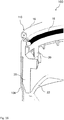
- FIG 1 shows a sectional illustration of a filter system 100 according to an embodiment of the invention.
- the filter system 100 for filtering a fluid with a frontal inlet and outlet 104 comprises a filter element 10, a filter housing 108, a coupling device 30 for coupling the filter system 100 to a receptacle 32 external to the filter system (in Figure 3 shown), as well as a seal holder 16 with a seal 18 for sealing the filter system on the receptacle 32.
- the coupling device 30 provides a plurality of coupling elements 36, which are at least partially in an axial direction L into one in the receptacle by a sliding and rotating movement 32 arranged coupling contour 34 can be introduced in order to hold and lock the filter system 100 in the receptacle 32 in an end position 38.
- the coupling device 30 comprises a clamping element 22 which, in the assembled state, clamps the filter system 100 axially against the receptacle 32.
- the clamping element 22 provides at least two elevations 23 in the axial direction.
- the coupling device 12 is connected to the seal holder 16, the seal holder 16 being designed as the end-face termination of the filter system 100.
- the seal 18 is arranged radially, so that it seals the filter system 100 radially from the receptacle 32 in the assembled state.
- the cut-open filter element 10 has a hollow cylindrical filter body 12 as the actually filtering element, which is stiffened by a support tube 26 which is arranged in its interior.
- the inlet of the fluid to be filtered runs on the outside of the filter element 10 between the filter body 12 and the filter housing 108.
- the fluid then passes through the filter body 12 and flows back through the outlet 104 centrally back into the outlet connection of the receptacle 32.
- the outlet 104 is against the Outlet connection 118 of a receiving carrier 33 is sealed with a radial seal 19.
- the filter system 100 can be attached with the coupling device 30, which is connected to a corresponding sealing arrangement 16, directly to a receptacle 32 external to the filter system, which is seated, for example, on a die-cast head of an internal combustion engine.
- the filter system 100 which can be arranged in a hanging, standing or lying position, is held on the receptacle 32 by the coupling device 30.
- the seal holder 16 can advantageously be connected to the coupling device 30.
- the coupling device 30 can be designed in the form of a bayonet connection so that the coupling elements 36, which are arranged on the coupling device 30, can slide into a coupling contour 34 located on the receptacle 32 when the filter system 100 is screwed into the receptacle 32 and when the Filter system 100 can slide into an end position 38. The filter system 100 is thereby locked in the receptacle 32.
- the spring preload must first be overcome again in order to then allow the coupling elements 36 to slide out over the coupling contour 34 and thus to be able to remove the filter system 100 from the receptacle 32.
- the coupling device 30 can expediently be made of a plastic, whereby thermoplastic materials can be used for lower mechanical requirements which allow a maximum surface pressure of up to 20 N / mm 2 , while for higher mechanical requirements thermosets can be used which have a maximum surface pressure of up to allow 80 N / mm 2 . Since, in particular, the coupling elements 36 are subjected to higher loads when sliding in the coupling contour 34, duromers represent a preferred embodiment. With these materials, the coupling elements 36 can also be designed in any shape, which is advantageous for the structural design of the coupling device 30 and the coupling contour 34 is.
- the receptacle 32 can, for example, be made of aluminum, which has a higher strength than plastics, so that no signs of wear and tear can occur on the receptacle 32, which can be part of the internal combustion engine, even if a filter system 100 is attached and replaced several times.
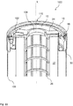
- FIG 2 is a perspective view of a filter housing 108 with seal holder 16, coupling device 30 and clamping element 22 can be seen according to an embodiment of the invention.
- the coupling device 30 provides a plurality of holding elements 40 for holding the clamping element 22, which in the exemplary embodiment shown are designed as a support for the clamping element 22 during assembly on the receptacle 32.
- the outlet 104 is provided with a circumferential radial seal 19 for sealing against an outlet connection 118 of a receiving carrier 33.
- FIG. 3 shows a longitudinal section of a filter system 100 mounted on a receptacle 32 according to an embodiment of the invention.
- the receptacle 32 itself is attached to a receptacle carrier 33.
- the seal holder 16 provides one or more connecting elements 20 for connection to the coupling device 30.
- a U-shaped groove is formed as the connecting element 20 of the coupling device 30 and the seal holder 16, into which the seal holder 16 engages.
- the filter element 10 is arranged in the filter housing 108 via a filter element holder 24 which is supported on the coupling device 30.
- Figure 3 a combination of a filter system 100 and a receptacle 32, the receptacle 32 having a coupling contour 34 with which one or more coupling elements 36 of a coupling device 30 of the filter system 100 can be coupled at least partially in an axial direction L by a sliding / rotating movement.
- FIG 4 a perspective view of a receptacle carrier 33 for a receptacle 32 according to an embodiment of the invention is shown, which has an outlet connector 118 for the outlet 104 of the filter system 100. Furthermore, three bores 42 for screwing to the receptacle 32 are arranged in the receiving carrier 33.
- Figure 5 shows a perspective view of a receptacle 32 according to an embodiment of the invention.
- the receptacle 32 has obliquely running coupling contours 34, in which the coupling elements 36 of the coupling device 30 can engage in order to reach the end position 38 during rotation and to latch and lock the filter system 100 there.
- Three bores 42 for connection to the receiving carrier 33 are also provided on the receptacle 32.
- FIG 6 is a perspective view of a coupling device 30 according to an embodiment of the invention.
- the coupling device 30 comprises a circular ring, on the inside of which coupling elements 36 for engaging in the coupling contour 34, as well as holding elements 40 for receiving the clamping element 22, are arranged.
- a U-shaped groove is also arranged as a connecting element 20 to the seal holder 16.
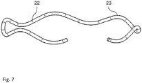
- Figure 7 shows a perspective view of a tensioning element 22 according to an embodiment of the invention.
- the tensioning element 22 is shown as a circularly bent wire with undulating elevations 23.
- the clamping element 22 can advantageously provide at least two elevations 23 in the axial direction L.
- the elevations 23 on the one hand, the prestressing force of the tensioning element 22 is applied, and, on the other hand, the elevations 23 have the advantage that if one elevation fails 23, for example, due to material breakage, further elevations 23 are present in order to nevertheless maintain the function in the form of the pretensioning force of the tensioning element 22.
- Figure 8 is an exploded view of a filter system 100 according to an embodiment of the invention. In this illustration, the interlocking of the various assembly elements and the assembly sequence of the filter system can be seen.
- a mounting carrier 33 which is attached to an internal combustion engine and has an outlet connection 118 for discharging the filtered fluid, such as oil, from the filter system 100 into the internal combustion engine, carries a mounting 32 for a filter system 100.
- the filter system 100 comprises a filter element 10 with a filter body 12, which is arranged in a filter housing 108.
- the fluid to be filtered passes from the outside between the filter housing 108 and the filter body 12 through the filter body 12 into the interior of the filter element and flows back out of the filter element 10 through the support tube 26 at the upper end.
- the filter element 10 is closed at the upper end by a coupling device 30, which coupling elements 36 for engaging and locking with coupling contours arranged in the receptacle 32 as well as holding elements 40 for supporting a tensioning element 22 which braces the filter system 100 and receptacle 32 against one another.
- the filter system 100 is closed by the seal holder 16, which is arranged in a groove-like connecting element 20 of the coupling device 30 and which on the one hand carries the seal 18 in a groove and tightly closes the filter system 100 with the filter housing 108, for example by a flanged edge.
- the tensioning element 22 is placed on the holding elements 40 on the inside of the coupling device 30.
- the radial seal 19 seals the support tube 26 on the outside against the outlet connection 118 of the receiving carrier 33 and thus the outlet 104 of the filter system 100.
- the filter system 100 is connected to the receptacle 32 for assembly on an internal combustion engine. By rotating the filter system 100 against one another against the receptacle 32, the coupling elements 36 of the coupling device 30 can grip into the coupling contours 34 of the receptacle 32 and thus lock in the end positions 38 of the coupling contours 34. In this case, the tensioning element 22 arranged in the coupling device 30 on the holding elements 40 is braced against the receptacle 32.
- FIG 9 shows a perspective view of a filter system 100 according to a further embodiment of the invention.
- the filter system 100 for filtering a fluid with a front inlet 102 and outlet 104 comprises a filter element 10, a filter housing 108, a coupling device 30 for coupling the filter system 100 to a receptacle 32 external to the filter system, and a one-piece seal holder 16 with a seal 18 for sealing the Filter system on the receptacle 32.
- the one-piece seal holder 16 includes the seal 18 essentially U-shaped, the one-piece seal holder 16 being connected to the filter housing 108 at an end edge 110 of the filter system 100.
- the one-piece seal holder 16 is designed as the frontal termination of the filter system 100.
- the filter system 100 is intended for use as a fuel filter.
- the filter system 100 can with the seal 18, for example a one-piece O-ring seal, which is U-shaped, i.e. enclosed on three sides, in the seal holder 16, directly against a filter-external receptacle 32, which is for example on a Die-cast head of an internal combustion engine sits to be sealed.
- the filter system 100 which can be arranged in a hanging, standing or lying position, is held on the receptacle 32 by the coupling device 30.
- the seal holder 16 can advantageously be connected to the coupling device 30.
- the seal holder 16 seals hydraulically tightly against the environment, i.e. both the seal holder 16 is tightly connected to the filter housing 108 and the seal 18 seals hydraulically tightly against the seal holder 16.
- test gases e.g. helium or air under water
- the one-piece seal holder 16 which is designed, for example, as a sheet metal part, can be connected to the filter housing 108 by welding, gluing, flanging or similar joining methods in order to create a permanently tight and mechanically firm connection.
- the contour for holding the seal 18 can be produced, for example, by hitting, hydroforming, rolling or similar forming processes in order to represent a one-piece seal holder 16 which comprises a U-shaped receptacle for the seal 18.
- FIG 10 is a perspective view of a seal retainer 16 is shown according to an embodiment of the invention.
- a plurality of connecting elements 20 for connection to the coupling device 30 are provided on the one-piece seal holder 16. In the embodiment shown, these are hook-shaped connecting parts 20 that can snap into a coupling device.
- FIG 11 shows a sectional view of a filter system 100 with a focus on seal holder 16 and coupling device 30 according to a further embodiment of the invention.
- the seal 18 lies at least radially and axially Direction on the one-piece seal holder 16.
- the one-piece seal holder 16 is positively connected to the coupling device 12.
- the filter element 10 is arranged in the filter housing 108 via a filter element holder 24 which is supported on the coupling device 30.
- the filter element holder 26 engages on the lower side in the coupling device 30 so that the filter element 10 is firmly clamped in the filter housing 108.
- the filter element 10, which is essentially formed from a filter body 12, has a support tube 26 inside for reinforcement.
- the outlet 104 of the filter system 100 runs inside the support tube 26, while the inlet 102 runs tangentially between the seal holder 16 and the filter housing 108 on one side and on the outer wall of the filter element 10.
- Figure 12 shows a longitudinal section of a filter system 100 mounted on a receptacle 32 according to an embodiment of the invention.
- the filter system 100 is pushed onto the receptacle 32, which is arranged, for example, on an internal combustion engine, and is connected to this receptacle 32 via the coupling device 30.
- the coupling device 30 comprises a quick coupling, for example a bayonet coupling.
- the coupling device 30 comprises a clamping element 22 which, in the assembled state, clamps the filter system 100 axially against the receptacle 32.
- the clamping element 22 is in the in Figure 12
- the longitudinal section shown cannot be seen, but is shown in Figure 15 recognizable.
- the seal 18 has a radially inward sealing function with respect to a longitudinal axis L, where the seal 18 rests against a side surface of the receptacle 32.
- the arrangement in Figure 12 thus represents a combination of a filter system 100 and a receptacle 32, the filter system 100 having a one-piece seal holder 16 with a seal 18 for sealing the filter system on the receptacle 32.
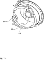
- Figure 13 shows a perspective view of part of an internal combustion engine with a receptacle 32 for a filter system 100 according to an embodiment of the invention.
- the hollow cylinder-shaped receptacle 32 has coupling contours 34 in which coupling elements 36 of a coupling device 30, for example cams of a bayonet connection, can engage and lock.
- an outlet nozzle can be seen which engages in the support tube 26 of the filter element 100 when the filter element 100 is installed and thus connects the outlet 104 of the filter system 100 to the internal combustion engine.
- FIG. 13 is a corresponding sectional view of a receptacle 32 for a filter system 100, as in FIG Figure 13 shown to see.
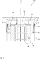
- Figure 15 shows a perspective view of a filter housing 108 with seal holder 16, coupling device 30 and tensioning element 22 according to a further embodiment of the invention.
- a seal 18 is inserted, which is U-shaped from the contours of the seal holder 16 is enclosed.
- the seal holder 16 is firmly connected to the connecting elements 20 with the coupling device 30 and latched.
- the coupling device 30 has coupling elements 36 of a quick coupling on its inside, one of which can be seen, which engage in corresponding coupling contours 34 which are arranged on a receptacle 32 and can lock with them.
- a tensioning element 22 is also arranged on the inside of the coupling device, which, for example, can be formed from spring steel wire.
- Figure 16 a sectional view of the seal holder 16 and coupling device 30 according to a further embodiment of the invention can be seen. It can be clearly seen how the connecting elements 20 engage in the coupling device 30. It can also be seen how the radially and axially acting seal 18 lies in the contour of the one-piece seal holder 16 and is enclosed by this in a U-shape.
- Figure 17 shows a further sectional view of seal holder 16 and coupling device 30 according to an embodiment of the invention.
- a coupling element 20 is arranged, for example molded on, as well as the clamping element 22 for bracing the filter system 100 against the receptacle 32.
Landscapes
- Chemical & Material Sciences (AREA)
- Chemical Kinetics & Catalysis (AREA)
- Engineering & Computer Science (AREA)
- Combustion & Propulsion (AREA)
- Lubrication Details And Ventilation Of Internal Combustion Engines (AREA)
- Filtration Of Liquid (AREA)
Description
- Die Erfindung betrifft ein Filtersystem zum Filtern eines Fluids mit einer Kupplungsvorrichtung, insbesondere zur Verwendung als Kraftstofffilter einer Brennkraftmaschine.
- Es ist bekannt, dass eine der Herausforderungen bei der Konstruktion von Wechselfiltersystemen darin liegt, eine zuverlässige Anbringung und Abdichtung an einer Aufnahme zu schaffen, an der das Filtersystem angebaut wird. Die mechanischen Schnittstellen müssen möglichst einfach und dennoch robust und zuverlässig ausgelegt sein. Das Filtersystem muss möglichst einfach, schnell und ohne Probleme wiederholt ausgetauscht werden können. Außerdem gilt es, eine Vielzahl von Anbausituationen mit ähnlichen Lösungen abzudecken, um kostengünstige Filtersysteme darstellen zu können.
- Kraftstofffilter verwenden gewöhnlich ein Einwegfilterelement, das nach vorbestimmten Zeitintervallen der Filterverwendung ausgewechselt wird. Das Einwegelement ist konventionell an dem Filteraufbaugrundteil durch einen Halte- oder Verriegelungsmechanismus befestigt, der lösbar ist, um das Entfernen des Elements für Auswechselzwecke zuzulassen. Es gibt zahlreiche konventionelle Grundteilhaltesysteme für Kraftstofffilterelemente. Viele solcher Haltesysteme sind äußerst unbequem in der Verwendung oder versagen sogar nach einer Zeit aufgrund der rauhen Umgebung des Kraftstofffiltereinsatzes.
- Die
US 5302284 A beschreibt einen Filteraufbau, der ein Grundteil, ein an dem Grundteil anbringbares Filterelement und einen Haltekragen zum Befestigen des Filterelements am Grundteil einschließt. Der Kragen hält eine wellenförmige Feder, die zwischen beabstandeten Schultern des Kragens gehalten wird. Das Grundteil bildet eine Aufnahmeeinrichtung zum Aufnehmen des Kopfes des Filterelements. Eine Rampe und eine Arretierung, die benachbart dem Ende der Rampe ist, sind vor dem Grundteil angeordnet. Der Haltekragen schließt weiter eine Nocke ein, die eine Sperrklinke aufweist. Die Nocke ist mit der Rampe in Eingriff bringbar, so dass, wenn der Kragen winkelmäßig gedreht wird, sich die Nocke auf der Rampe bewegt und die Sperrklinke in die Arretierung unter der Vorspannung der Feder eingreift, um das Filterelement am Grundteil zu verriegeln. - In
DE 10 2010 035465 A1 wird eine Filtervorrichtung offenbart, die einen Wechselfilter aufweist, der stirnseitig einen koaxialen Anschlusszylinder hat, auf dessen Mantelfläche eine umlaufende Dichtungsnut für eine Radialdichtung und eine Kupplungsvorrichtung vorliegt. Sowohl die Dichtungsnut als auch die Kupplungsvorrichtung werden durch ein gemeinsames Bauteil gebildet. - Ferner ist ein umlaufendes Federelement offenbart, das sich einerseits an dem Anschlusszylinder und andererseits an dem Filterkopf abstützt und eine Rastverbindung vorspannt. Das Federelement ist filterkopfseitig befestigt.
-
EP 0 221 675 A2 offenbart eine separate Ausbildung von Kupplungselement und Dichtung, jedoch keinen separaten Dichtungshalter. Die Dichtung ist dort direkt in einem umgebördelten Rand des Gehäusetopfs eingelegt, während das Kupplungselement mit dem Gehäusetopf auf der inneren Mantelfläche durch (Punkt)Schweißungen verbunden ist. - Eine Aufgabe der Erfindung ist es daher, ein Filtersystem zum Filtern eines Fluids zu schaffen, das eine robuste und kostengünstige Möglichkeit vorsieht, um eine zuverlässige lösbare Halterung des Filtersystems an einem filtersystemexternen Aufnahmeteil zu gewährleisten. Weiterhin soll eine zuverlässige Abdichtung des Filtersystems zu dem Aufnahmeteil sowie zwischen Einlass und Auslass bereitgestellt werden.
- Die vorgenannte Aufgabe wird nach einem Aspekt der Erfindung gelöst von einem Filtersystem, bei dem eine Kupplungsvorrichtung ein oder mehrere Kupplungselemente vorsieht, welche durch eine Schiebe-Dreh-Bewegung zumindest teilweise in einer axialen Richtung in eine in einer Aufnahme angeordnete Kupplungskontur einführbar sind, um so das Filtersystem in der Aufnahme in einer Endposition zu halten und zu verriegeln.
- Günstige Ausgestaltungen und Vorteile der Erfindung ergeben sich aus den weiteren Ansprüchen, der Beschreibung und der Zeichnung.
- Es wird ein Filtersystem zum Filtern eines Fluids mit stirnseitigem Einlass und Auslass vorgeschlagen, das wenigstens ein Filterelement, ein Filtergehäuse, eine Kupplungsvorrichtung zur Kopplung des Filtersystems an eine filtersystemexterne Aufnahme, sowie einen Dichtungshalter mit einer Dichtung zur Abdichtung des Filtersystems an der Aufnahme umfasst. Dabei sieht die Kupplungsvorrichtung ein oder mehrere Kupplungselemente vor, welche durch eine Schiebe-Dreh-Bewegung zumindest teilweise in einer axialen Richtung in eine in der Aufnahme angeordnete Kupplungskontur einführbar sind, um so das Filtersystem in der Aufnahme in einer Endposition zu halten und zu verriegeln. Mit anderen Worten ist die Kupplungsvorrichtung als Schnellkupplung ausgeführt.
- Das erfindungsgemäße Filtersystem kann mit der Kupplungsvorrichtung, die mit einer entsprechenden Dichtungsanordnung verbunden ist, direkt an einer filtersystemexternen Aufnahme, die bspw. an einem Druckgusskopf einer Brennkraftmaschine sitzt, angebracht werden. Dabei wird das Filtersystem, das hängend, stehend oder liegend angeordnet sein kann, mit der Kupplungsvorrichtung an der Aufnahme gehalten. Wenn das Filtersystem angebracht wird, ist es günstig, wenn die Dichtung direkt mit dem Filtersystem verbunden ist und so bei der Montage nicht herausfallen und/oder beschädigt werden kann. Der Dichtungshalter ist mit der Kupplungsvorrichtung verbunden.
- Die Kupplungsvorrichtung kann in Form einer Bajonettverbindung ausgebildet sein, so dass die Kupplungselemente, welche an der Kupplungsvorrichtung angeordnet sind, beim Eindrehen des Filtersystems in die Aufnahme in eine an der Aufnahme befindliche Kupplungskontur gleiten können und bei weiterem Drehen des Filtersystems dabei in eine Endposition gleiten können, wodurch das Filtersystem in der Aufnahme verriegelt wird.
- Diese Montageprozedur wird durch ein an der Kupplungsvorrichtung angebrachtes Spannelement, bspw. in Form einer Druckfeder, unterstützt, welches in axialer Richtung wirkt und bei Überwinden der Federkraft des Spannelements das Filtersystem in die Endposition gleiten lässt und sodann in dieser Endposition durch die Federvorspannung verriegelt. Zum Ausdrehen des Filtersystems muss dann zunächst wieder die Federvorspannung überwunden werden, um anschließend die Kupplungselemente über die Kupplungskontur herausgleiten zu lassen und so das Filtersystem von der Aufnahme abnehmen zu können.
- Die Kupplungsvorrichtung kann zweckmäßigerweise aus einem Kunststoff ausgebildet sein, wobei für geringere mechanische Anforderungen thermoplastische Werkstoffe eingesetzt werden können, welche eine maximale Flächenpressung bis zu 20 N/mm2 zulassen, während für höhere mechanische Anforderungen Duromere eingesetzt werden können, welche eine maximale Flächenpressung bis zu 80 N/mm2 erlauben. Da insbesondere die Kupplungselemente höher belastet sind beim Gleiten in der Kupplungskontur, stellen Duromere eine bevorzugte Ausführungsform dar. Mit diesen Werkstoffen lassen sich die Kupplungselemente auch in beliebiger Form gestalten, was für die konstruktive Ausführung der Kupplungsvorrichtung und der Kupplungskontur von Vorteil ist. Die Aufnahme kann bspw. aus Aluminium-Druckguss gefertigt sein, das eine höhere Festigkeit als Kunststoffe, insbesondere ein geringfügig höhere Festigkeit als Duromere, aufweist, so dass auch bei mehrfachem Anbringen und Austauschen eines Filtersystems keine Verschleißerscheinungen an der Aufnahme, die Bestandteil der Brennkraftmaschine sein kann, auftreten können.
- Von weiterem Vorteil des erfindungsgemäßen Filtersystems ist, dass das Spannelement, bspw. in Form einer wellenförmigen Druckfeder nicht an der Aufnahme, die ja Bestandteil der Brennkraftmaschine ist, angebracht ist, sondern an der Kupplungsvorrichtung angeordnet ist. Dadurch gestaltet sich die konstruktive Form der Aufnahme einfacher und auch die Befestigung des Spannelements ist in der Kupplungsvorrichtung flexibler gestaltbar. Da die Kupplungsvorrichtung in Kunststoff ausgeführt ist, können günstig bspw. zusätzliche Nasen als Halteelemente angebracht werden, welche das Spannelement halten und worüber es leicht eingelegt oder auch sogar ausgetauscht werden könnte.
- Vorteilhaft kann so die Kupplungsvorrichtung ein Spannelement umfassen, das im montierten Zustand das Filtersystem axial gegen die Aufnahme verspannt. Durch das Wirken des Spannelements kommt die Funktion einer Schnellkupplung, bspw. in Form eines Bajonetts zum Tragen, indem das Filtersystem durch Überwinden einer Vorspannkraft des Spannelements in die Endposition der Kupplungskontur einrasten kann.
- Günstigerweise kann das Spannelement wenigstens zwei, insbesondere bspw. fünf, Erhebungen in axialer Richtung vorsehen. Durch die Erhebungen wird zum einen die Vorspannkraft des Spannelements aufgebracht, zum anderen haben die Erhebungen den Vorteil, dass bei Versagen einer Erhebung bspw. durch Materialbruch, weitere Erhebungen vorhanden sind, um die Funktion in Form der Vorspannkraft des Spannelements dennoch aufrechtzuerhalten.
- In einer vorteilhaften Ausgestaltung kann die Kupplungsvorrichtung mit dem Dichtungshalter verbunden sein. Dadurch ergibt sich eine stabile und dauerhafte Abdichtung beim Montieren des Filtersystems an der Aufnahme. Des Weiteren ist durch die feste Verbindung des Dichtungshalters mit dem Filtergehäuse auch die Kupplungsvorrichtung fest und stabil mit dem Gehäuse verbunden.
- Die Kupplungsvorrichtung sieht ein oder mehrere Halteelemente zur Halterung des Spannelementes vor. Auf diese Weise ist das Spannelement in der Kupplungsvorrichtung günstig positionierbar und kann leicht montiert oder im Bedarfsfall sogar ausgetauscht werden, sollten sich Materialermüdung oder Versagen des Spannelements einstellen.
- Vorteilhaft kann die Dichtung radial angeordnet sein, so dass diese das Filtersystem im montierten Zustand radial zur Aufnahme abdichtet. Da die Aufnahme sinnvollerweise als ein Stutzen ausgeführt sein kann, über den das Filtersystem geschoben werden kann und worüber auch Einlass und Auslass des Filtersystems abgedeckt werden, ist eine radiale Dichtung des Filtersystems sinnvoll und günstig, um die Funktion dauerhaft sicherzustellen.
- Der Dichtungshalter ist als der stirnseitige Abschluss des Filtersystems ausgebildet. Damit ist auch eine dauerhafte und stabile Abdichtung am stirnseitigen Ende des Filtergehäuses darstellbar. Der einteilige Dichtungshalter, der bspw. als ein Blechteil ausgeführt ist, kann mit dem Filtergehäuse durch Schweißen, Kleben, Bördeln oder ähnlichen Fügeverfahren verbunden werden, um so eine dauerhaft dichte und mechanisch feste Verbindung darzustellen. Die Kontur für die Halterung der Dichtung kann dabei bspw. durch Schlagen, Innenhochdruckumformen ("Hydroforming"), Rollen oder ähnliche Umformverfahren hergestellt werden, um einen einteiligen Dichtungshalter, der eine U-förmige Aufnahme für die Dichtung umfasst, darzustellen.
- Günstigerweise kann der Dichtungshalter ein oder mehrere Verbindungselemente zur Verbindung mit der Kupplungsvorrichtung vorsehen. Über diese Verbindungselemente, die bspw. in Form von Haken oder Klemmen ausgebildet sein können, lassen sich der Dichtungshalter und die Kupplungsvorrichtung fest verbinden. Auch ist so eine unter Umständen sogar lösbare Verbindung darstellbar, wenn die Verbindungselemente bspw. als Rastelemente ausgebildet sind.
- Zweckmäßigerweise kann das Filterelement über einen Filterelementhalter, der sich an der Kupplungsvorrichtung abstützt, in dem Filtergehäuse angeordnet sein. Auf diese Weise kann das Filterelement fest und stabil in dem Filtergehäuse abgestützt und evtl. verspannt werden. Weiter ist auch ein Austausch des Filterelements durch Entfernen des Filterelementhalters denkbar.
- Nach einem weiteren Aspekt betrifft die Erfindung eine Kombination aus einem Filtersystem und einer Aufnahme, wobei die Aufnahme eine Kupplungskontur aufweist, mit welcher ein oder mehrere Kupplungselemente einer Kupplungsvorrichtung des Filtersystems durch eine Schiebe-Dreh-Bewegung zumindest teilweise in einer axialen Richtung kuppelbar sind. Da die Schnittstellen des Filtersystems mit dem Dichtungshalter und der Kupplungsvorrichtung auf die filtersystemexterne Aufnahme sich in ihrer Funktionsweise entsprechen und ergänzen, ist es vorteilhaft, wenn die Kombination, bspw. zu Materialpaarung, Bauteiloberflächen und Fügeverfahren, aufeinander abgestimmt ist.
- Nach einem weiteren Aspekt betrifft die Erfindung die Verwendung des Filtersystems als Kraftstofffilter. Dabei kann das Filtersystem sowohl als Wechselfiltersystem als auch als Lebensdauerfilter eingesetzt werden.
- Nach einem weiteren Aspekt der Erfindung wird ein Filtersystem zum Filtern eines Fluids mit stirnseitigem Einlass und Auslass vorgeschlagen, das wenigstens ein Filterelement, ein Filtergehäuse, eine Schnellkupplungsvorrichtung zur Kopplung des Filtersystems mit einer filtersystemexternen Aufnahme, sowie einen einteiligen Dichtungshalter mit einer Dichtung zur Abdichtung des Filtersystems an der Aufnahme umfasst. Dabei umfasst der einteilige Dichtungshalter die Dichtung im Wesentlichen U-förmig, wobei der einteilige Dichtungshalter an einem stirnseitigen Rand des Filtergehäuses mit dem Filtergehäuse verbunden ist.
- Das erfindungsgemäße Filtersystem kann mit der Dichtung, bspw. einer einteiligen O-RingDichtung, die U-förmig, also an drei Seiten umschlossen, in dem Dichtungshalter angeordnet ist, direkt gegen eine filterexterne Aufnahme, die bspw. an einem Druckgusskopf einer Brennkraftmaschine sitzt, abgedichtet werden. Dabei wird das Filtersystem, das hängend, stehend oder liegend angeordnet sein kann, mit der Kupplungsvorrichtung an der Aufnahme gehalten. Wenn das Filtersystem angeschraubt wird, ist es günstig, wenn die Dichtung direkt mit dem Filtersystem verbunden ist und so bei der Montage nicht herausfallen und/oder beschädigt werden kann. Günstigerweise kann der Dichtungshalter mit der Kupplungsvorrichtung verbunden sein.
- Es ist vorteilhaft für die Funktion des Filtersystems, wenn der Dichtungshalter hydraulisch dicht gegen die Umgebung abdichtet, also sowohl der Dichtungshalter mit dem Filtergehäuse dicht verbunden ist, als auch die Dichtung gegen den Dichtungshalter hydraulisch dicht abdichtet. Üblicherweise werden Normleckagen von max. 0,5 Ncm3/min im Verbund mit Testgasen (bspw. Helium oder Luft unter Wasser) zugelassen. Das bedeutet, dass die Nut im Dichtungshalter, in der die Dichtung anliegt, eine hohe Oberflächengüte aufweist und typischerweise keine Riefen über 0,1 mm aufweisen darf, sowie Rauhigkeitswerte Rz für die Nut unter 40 µm liegen sollten. Der Rauhigkeitswert Rz ist dabei die sog. gemittelte Rauhtiefe, d.h. der Mittelwert aus den gemessenen Rauhtiefen.
- Der einteilige Dichtungshalter, der bspw. als ein Blechteil ausgeführt ist, kann mit dem Filtergehäuse durch Schweißen, Kleben, Bördeln oder ähnlichen Fügeverfahren verbunden werden, um so eine dauerhaft dichte und mechanisch feste Verbindung darzustellen. Die Kontur für die Halterung der Dichtung kann dabei bspw. durch Schlagen, Innenhochdruckumformen ("Hydroforming"), Rollen oder ähnliche Umformverfahren hergestellt werden, um einen einteiligen Dichtungshalter, der eine U-förmige Aufnahme für die Dichtung umfasst, darzustellen.
- Vorteilhaft kann die Dichtung im bestimmungsgemäßen Einsatz wenigstens in radialer und in axialer Richtung an dem einteiligen Dichtungshalter anliegen. Die Dichtung wird dabei von dem einteiligen Dichtungshalter geführt und liegt so in einer Nut des Dichtungshalters. Die Dichtung wird dabei von innen eingelegt. Auf diese Weise kann die Dichtung sowohl radial gegen eine Aufnahme, bspw. in Form eines Anschlussstutzens einer Brennkraftmaschine, als auch axial gegen eine Wand des Dichtungshalters abdichten, wodurch auch im rauen Betrieb einer Fahrzeugmontageposition eine zuverlässige Abdichtung gewährleistet ist.
- Günstigerweise kann die Dichtung so eine radial zu einer Längsachse nach innen abdichtende Funktion aufweisen. Die Dichtung liegt in dieser Anordnung von außen auf einer Aufnahme auf und dichtet so das Filtersystem zur Aufnahme gegen die Umgebung ab.
- In einer vorteilhaften Ausgestaltung kann der einteilige Dichtungshalter als der stirnseitige Abschluss des Filtersystems ausgebildet sein. Auf diese Weise wird das Filtersystem an der Stirnseite günstig abgedichtet und erhält zugleich einen mechanisch zuverlässigen und dauerhaften Abschluss. Die Dichtung kann so das Filtersystem günstig zur Aufnahme abdichten.
- Der einteilige Dichtungshalter ist mit der Kupplungsvorrichtung formschlüssig verbunden. Eine solch feste Verbindung gewährleistet, dass die Dichtungsfunktion mit der Haltefunktion zusammen günstig kombiniert ist und dadurch beim Montieren des Filtersystems an der Aufnahme auch eine dauerhafte Dichtung gegeben ist.
- Günstigerweise können am einteiligen Dichtungshalter ein oder mehrere Verbindungselemente zur Verbindung mit der Kupplungsvorrichtung vorgesehen sein. Über diese Verbindungselemente kann der Dichtungshalter in die Kupplungsvorrichtung eingerastet werden und so eine dauerhafte und stabile Verbindung eingehen.
- In einer vorteilhaften Ausgestaltung kann die Kupplungsvorrichtung eine Schnellkupplung umfassen. Bspw. kann die Kupplungsvorrichtung als Bajonettverbindung ausgebildet sein, so dass das Filtersystem über eine kombinierte Dreh-/Schiebebewegung auf die Aufnahme aufgesetzt und verriegelt werden kann.
- Vorteilhaft kann die Kupplungsvorrichtung ein Spannelement umfassen, das im montierten Zustand das Filtersystem axial gegen die Aufnahme verspannt. Gerade beim Einsatz einer Schnellkupplung wie einer Bajonettverbindung ist eine Verspannung günstig, welche das Filtersystem dadurch in einer Endposition der Bajonettverbindung hält.
- In einer günstigen Ausgestaltung kann das Filterelement über einen Filterelementhalter, der sich an der Kupplungsvorrichtung abstützt, in dem Filtergehäuse angeordnet sein. Auf diese Weise lässt sich das Filterelement in dem Filtergehäuse verspannen und so stabil und sicher auch bei rauen Einsatzbedingungen wie im Kraftfahrzeugbetrieb üblich lagern.
- Nach einem weiteren Aspekt betrifft die Erfindung eine Kombination aus einem Filtersystem und einer Aufnahme, wobei das Filtersystem einen einteiligen Dichtungshalter mit einer Dichtung zur Abdichtung des Filtersystems an der Aufnahme aufweist. Da die Schnittstellen des Filtersystems mit dem Dichtungshalter und der Kupplungsvorrichtung auf die filtersystemexterne Aufnahme sich in ihrer Funktionsweise entsprechen und ergänzen, ist es vorteilhaft, wenn die Kombination, bspw. zu Materialpaarung, Bauteiloberflächen und Fügeverfahren, aufeinander abgestimmt ist.
- Nach einem weiteren Aspekt betrifft die Erfindung die Verwendung des Filtersystems als Kraftstofffilter. Dabei kann das Filtersystem sowohl als Wechselfiltersystem als auch als Lebensdauerfilter eingesetzt werden.
- Weitere Vorteile ergeben sich aus der folgenden Zeichnungsbeschreibung. In den Zeichnungen sind Ausführungsbeispiele der Erfindung dargestellt. Die Zeichnungen, die Beschreibung und Ansprüche enthalten zahlreiche Merkmale in Kombination. Der Fachmann wird die Merkmale zweckmäßigerweise auch einzeln betrachten und zu sinnvollen weiteren Kombinationen zusammenfassen. Es zeigen beispielhaft:
- Fig. 1
- eine Schnittdarstellung eines Filtersystems nach einem Ausführungsbeispiel der Erfindung;
- Fig. 2
- eine perspektivische Ansicht eines Filtergehäuses mit Dichtungshalter, Kupplungsvorrichtung und Spannelement nach einem Ausführungsbeispiel der Erfindung;
- Fig. 3
- einen Längsschnitt eines an einer Aufnahme montierten Filtersystems nach einem Ausführungsbeispiel der Erfindung;
- Fig. 4
- eine perspektivische Ansicht eines Aufnahmeträgers für eine Aufnahme nach einem Ausführungsbeispiel der Erfindung;
- Fig. 5
- eine perspektivische Ansicht einer Aufnahme nach einem Ausführungsbeispiel der Erfindung;
- Fig. 6
- eine perspektivische Ansicht einer Kupplungsvorrichtung nach einem Ausführungsbeispiel der Erfindung; und
- Fig. 7
- eine perspektivische Ansicht eines Spannelements nach einem Ausführungsbeispiel der Erfindung;
- Fig. 8
- eine Explosionsdarstellung eines Filtersystems nach einem Ausführungsbeispiel der Erfindung;
- Fig. 9
- eine perspektivische Ansicht eines Filtersystems nach einem Ausführungsbeispiel der Erfindung;
- Fig. 10
- eine perspektivische Ansicht eines Dichtungshalters nach einem Ausführungsbeispiel der Erfindung;
- Fig. 11
- eine Schnittdarstellung eines Filtersystems mit Fokus auf Dichtungshalter und Kupplungsvorrichtung nach einem weiteren Ausführungsbeispiel der Erfindung;
- Fig. 12
- einen Längsschnitt eines an einer Aufnahme montierten Filtersystems nach einem Ausführungsbeispiel der Erfindung;
- Fig. 13
- eine perspektivische Ansicht eines Teils einer Brennkraftmaschine mit Aufnahme für ein Filtersystem nach einem Ausführungsbeispiel der Erfindung;
- Fig. 14
- eine Schnittdarstellung einer Aufnahme für ein Filtersystem nach einem Ausführungsbeispiel der Erfindung;
- Fig. 15
- eine perspektivische Ansicht eines Filtergehäuses mit Dichtungshalter, Kupplungsvorrichtung und Spannelement nach einem weiteren Ausführungsbeispiel der Erfindung;
- Fig. 16
- eine Schnittdarstellung von Dichtungshalter und Kupplungsvorrichtung nach einem weiteren Ausführungsbeispiel der Erfindung; und
- Fig. 17
- eine weitere Schnittdarstellung von Dichtungshalter und Kupplungsvorrichtung nach einem Ausführungsbeispiel der Erfindung.
- In den Figuren sind gleiche oder gleichartige Komponenten mit gleichen Bezugszeichen beziffert. Die Figuren zeigen lediglich Beispiele und sind nicht beschränkend zu verstehen.
-
Figur 1 zeigt eine Schnittdarstellung eines Filtersystems 100 nach einem Ausführungsbeispiel der Erfindung. Das Filtersystem 100 zum Filtern eines Fluids mit stirnseitigem Einlass und Auslass 104, umfasst ein Filterelement 10, ein Filtergehäuse 108, eine Kupplungsvorrichtung 30 zur Kopplung des Filtersystems 100 an eine filtersystemexterne Aufnahme 32 (inFigur 3 dargestellt), sowie einen Dichtungshalter 16 mit einer Dichtung 18 zur Abdichtung des Filtersystems an der Aufnahme 32. Dabei sieht die Kupplungsvorrichtung 30 mehrere Kupplungselemente 36 vor, welche durch eine Schiebe-Dreh-Bewegung zumindest teilweise in einer axialen Richtung L in eine in der Aufnahme 32 angeordnete Kupplungskontur 34 einführbar sind, um so das Filtersystem 100 in der Aufnahme 32 in einer Endposition 38 zu halten und zu verriegeln. Die Kupplungsvorrichtung 30 umfasst ein Spannelement 22, das im montierten Zustand das Filtersystem 100 axial gegen die Aufnahme 32 verspannt. Dabei sieht das Spannelement 22 wenigstens zwei Erhebungen 23 in axialer Richtung vor. Die Kupplungsvorrichtung 12 ist mit dem Dichtungshalter 16 verbunden, wobei der Dichtungshalter 16 als der stirnseitige Abschluss des Filtersystems 100 ausgebildet ist. Die Dichtung 18 ist radial angeordnet, so dass diese das Filtersystem 100 im montierten Zustand radial zur Aufnahme 32 abdichtet. - Das aufgeschnittene Filterelement 10 weist einen hohlzylinderförmigen Filterkörper 12 als eigentlich filterndes Element auf, der von einem Stützrohr 26, welches in seinem Inneren angeordnet ist, ausgesteift wird. Der Einlass des zu filternden Fluids verläuft auf der Außenseite des Filterelements 10 zwischen Filterkörper 12 und Filtergehäuse 108. Das Fluid tritt dann durch den Filterkörper 12 und strömt durch den Auslass 104 zentral wieder zurück in den Auslassstutzen der Aufnahme 32. Der Auslass 104 wird gegen den Auslassstutzen 118 eines Aufnahmeträgers 33 mit einer Radialdichtung 19 abgedichtet.
- Das erfindungsgemäße Filtersystem 100 kann mit der Kupplungsvorrichtung 30, die mit einer entsprechenden Dichtungsanordnung 16 verbunden ist, direkt an einer filtersystemexternen Aufnahme 32, die bspw. an einem Druckgusskopf einer Brennkraftmaschine sitzt, angebracht werden. Dabei wird das Filtersystem 100, das hängend, stehend oder liegend angeordnet sein kann, mit der Kupplungsvorrichtung 30 an der Aufnahme 32 gehalten. Wenn das Filtersystem 100 angebracht wird, ist es günstig, wenn die Dichtung 18 direkt mit dem Filtersystem 100 verbunden ist und so bei der Montage nicht herausfallen und/oder beschädigt werden kann. Günstigerweise kann der Dichtungshalter 16 mit der Kupplungsvorrichtung 30 verbunden sein.
- Die Kupplungsvorrichtung 30 kann in Form einer Bajonettverbindung ausgebildet sein, so dass die Kupplungselemente 36, welche an der Kupplungsvorrichtung 30 angeordnet sind, beim Eindrehen des Filtersystems 100 in die Aufnahme 32 in eine an der Aufnahme 32 befindliche Kupplungskontur 34 gleiten können und bei weiterem Drehen des Filtersystems 100 dabei in eine Endposition 38 gleiten können. Hierdurch wird das Filtersystem 100 in der Aufnahme 32 verriegelt.
- Diese Montageprozedur wird zweckmäßigerweise durch ein an der Kupplungsvorrichtung 30 angebrachtes Spannelement 22, bspw. in Form einer Druckfeder, unterstützt, welches in axialer Richtung L wirkt und bei Überwinden der Federkraft das Filtersystem 100 in die Endposition 38 gleiten lässt und sodann in dieser Endposition 38 durch die Federvorspannung verriegelt. Zum Ausdrehen des Filtersystems 100 muss dann zunächst wieder die Federvorspannung überwunden werden, um anschließend die Kupplungselemente 36 über die Kupplungskontur 34 herausgleiten zu lassen und so das Filtersystem 100 von der Aufnahme 32 abnehmen zu können.
- Die Kupplungsvorrichtung 30 kann zweckmäßigerweise aus einem Kunststoff ausgebildet sein, wobei für geringere mechanische Anforderungen thermoplastische Werkstoffe eingesetzt werden können, welche eine maximale Flächenpressung bis zu 20 N/mm2 zulassen, während für höhere mechanische Anforderungen Duromere eingesetzt werden können, welche eine maximale Flächenpressung bis zu 80 N/mm2 erlauben. Da insbesondere die Kupplungselemente 36 höher belastet sind beim Gleiten in der Kupplungskontur 34, stellen Duromere eine bevorzugte Ausführungsform dar. Mit diesen Werkstoffen lassen sich die Kupplungselemente 36 auch in beliebiger Form gestalten, was für die konstruktive Ausführung von Vorteil der Kupplungsvorrichtung 30 und der Kupplungskontur 34 ist. Die Aufnahme 32 kann bspw. aus Aluminium gefertigt sein, das eine höhere Festigkeit als Kunststoffe aufweist, so dass auch bei mehrfachem Anbringen und Austauschen eines Filtersystems 100 keine Verschleißerscheinungen an der Aufnahme 32, die Bestandteil der Brennkraftmaschine sein kann, auftreten können.
- In
Figur 2 ist eine perspektivische Ansicht eines Filtergehäuses 108 mit Dichtungshalter 16, Kupplungsvorrichtung 30 und Spannelement 22 nach einem Ausführungsbeispiel der Erfindung zu sehen. Die Kupplungsvorrichtung 30 sieht mehrere Halteelemente 40 zur Halterung des Spannelementes 22 vor, die in dem gezeigten Ausführungsbeispiel als eine Abstützung für das Spannelement 22 bei der Montage an die Aufnahme 32 ausgebildet sind. Auf der Innenseite der Kupplungsvorrichtung 30 sind mehrere Kupplungselemente 36 zu erkennen, welche in eine entsprechende Kupplungskontur 34 einer Aufnahme 32 eingreifen können. Der Auslass 104 ist mit einer umlaufenden Radialdichtung 19 zum Abdichten gegen einen Auslassstutzen 118 eines Aufnahmeträgers 33 versehen. -
Figur 3 zeigt einen Längsschnitt eines an einer Aufnahme 32 montierten Filtersystems 100 nach einem Ausführungsbeispiel der Erfindung. Die Aufnahme 32 selbst ist an einem Aufnahmeträger 33 angebracht. Der Dichtungshalter 16 sieht ein oder mehrere Verbindungselemente 20 zur Verbindung mit der Kupplungsvorrichtung 30 vor. Als Verbindungselement 20 von Kupplungsvorrichtung 30 und Dichtungshalter 16 ist in dem gezeigten Ausführungsbeispiel eine U-förmige Nut ausgebildet, in welche der Dichtungshalter 16 eingreift. Das Filterelement 10 ist über einen Filterelementhalter 24, der sich an der Kupplungsvorrichtung 30 abstützt, in dem Filtergehäuse 108 angeordnet. - So zeigt
Figur 3 eine Kombination aus einem Filtersystem 100 und einer Aufnahme 32, wobei die Aufnahme 32 eine Kupplungskontur 34 aufweist, mit welcher ein oder mehrere Kupplungselemente 36 einer Kupplungsvorrichtung 30 des Filtersystems 100 durch eine Schiebe-Dreh-Bewegung zumindest teilweise in einer axialen Richtung L kuppelbar sind. - In
Figur 4 ist eine perspektivische Ansicht eines Aufnahmeträgers 33 für eine Aufnahme 32 nach einem Ausführungsbeispiel der Erfindung dargestellt, der einen Auslassstutzen 118 für den Auslass 104 des Filtersystems 100 aufweist. Weiter sind in dem Aufnahmeträger 33 drei Bohrungen 42 zur Verschraubung mit der Aufnahme 32 angeordnet. -
Figur 5 zeigt eine perspektivische Ansicht einer Aufnahme 32 nach einem Ausführungsbeispiel der Erfindung. Die Aufnahme 32 weist schräg verlaufende Kupplungskonturen 34 auf, in welche die Kupplungselemente 36 der Kupplungsvorrichtung 30 eingreifen können, um bei einer Drehung in die Endposition 38 zu gelangen und dort das Filtersystem 100 zu verrasten und verriegeln. Auch an der Aufnahme 32 sind drei Bohrungen 42 zur Verbindung mit dem Aufnahmeträger 33 angebracht. - In
Figur 6 ist eine perspektivische Ansicht einer Kupplungsvorrichtung 30 nach einem Ausführungsbeispiel der Erfindung dargestellt. Die Kupplungsvorrichtung 30 umfasst einen kreisförmigen Ring, auf dessen Innenseite Kupplungselemente 36 zum Eingriff in die Kupplungskontur 34, sowie Halteelemente 40 zur Aufnahme des Spannelements 22 angeordnet sind. Weiter ist eine U-förmige Nut als Verbindungselement 20 zum Dichtungshalter 16 angeordnet. -
Figur 7 zeigt eine perspektivische Ansicht eines Spannelements 22 nach einem Ausführungsbeispiel der Erfindung. Das Spannelement 22 ist in dem gezeigten Ausführungsbeispiel als kreisförmig gebogener Draht dargestellt mit wellenförmigen Erhebungen 23. - Günstigerweise kann das Spannelement 22 wenigstens zwei Erhebungen 23 in axialer Richtung L vorsehen. Durch die Erhebungen 23 wird zum einen die Vorspannkraft des Spannelements 22 aufgebracht, zum anderen haben die Erhebungen 23 den Vorteil, dass bei Versagen einer Erhebung 23 bspw. durch Materialbruch, weitere Erhebungen 23 vorhanden sind, um die Funktion in Form der Vorspannkraft des Spannelements 22 dennoch aufrechtzuerhalten.
- In
Figur 8 ist eine Explosionsdarstellung eines Filtersystems 100 nach einem Ausführungsbeispiel der Erfindung dargestellt. In dieser Darstellung sind das Ineinandergreifen der verschiedenen Montageelemente sowie die Montagereihenfolge des Filtersystems zu erkennen. - Ein Aufnahmeträger 33, der an einer Brennkraftmaschine angebracht ist und einen Auslassstutzen 118 zum Auslass des gefilterten Fluids wie beispielsweise Öl aus dem Filtersystem 100 in die Brennkraftmaschine aufweist, trägt eine Aufnahme 32 für ein Filtersystem 100. Das Filtersystem 100 umfasst ein Filterelement 10 mit einem Filterkörper 12, der in einem Filtergehäuse 108 angeordnet ist. Das zu filternde Fluid tritt von außen zwischen Filtergehäuse 108 und Filterkörper 12 durch den Filterkörper 12 in den Innenbereich des Filterelements und strömt durch das Stützrohr 26 am oberen Ende wieder aus dem Filterelement 10. Das Filterelement 10 wird am oberen Ende abgeschlossen von einer Kupplungsvorrichtung 30, welche Kupplungselemente 36 zum Eingreifen und Verrasten mit in der Aufnahme 32 angeordneten Kupplungskonturen sowie Halteelemente 40 zum Abstützen eines Spannelements 22 aufweist, welches Filtersystem 100 und Aufnahme 32 gegeneinander verspannt. Das Filtersystem 100 wiederum wird abgeschlossen durch den Dichtungshalter 16, der in einem nutartigen Verbindungselement 20 der Kupplungsvorrichtung 30 angeordnet ist und der zum einen die Dichtung 18 in einer Nut trägt sowie das Filtersystem 100 durch einen beispielsweise umgebördelten Rand mit dem Filtergehäuse 108 dicht verschließt.
- Das Spannelement 22 wird auf der Innenseite der Kupplungsvorrichtung 30 auf die Halteelemente 40 gelegt. Die Radialdichtung 19 dichtet das Stützrohr 26 auf der Außenseite gegen den Auslassstutzen 118 des Aufnahmeträgers 33 und damit den Auslass 104 des Filtersystems 100 ab. Das Filtersystem 100 wird zur Montage an einer Brennkraftmaschine an die Aufnahme 32 angeschlossen. Durch Gegeneinanderverdrehen des Filtersystems 100 gegen die Aufnahme 32 können die Kupplungselemente 36 der Kupplungsvorrichtung 30 in die Kupplungskonturen 34 der Aufnahme 32 greifen und so in den Endpositionen 38 der Kupplungskonturen 34 verrasten. Dabei wird das in der Kupplungsvorrichtung 30 auf den Halteelementen 40 angeordnete Spannelement 22 gegen die Aufnahme 32 verspannt.
-
Figur 9 zeigt eine perspektivische Ansicht eines Filtersystems 100 nach einem weiteren Ausführungsbeispiel der Erfindung. Das Filtersystem 100 zum Filtern eines Fluids mit stirnseitigem Einlass 102 und Auslass 104, umfasst ein Filterelement 10, ein Filtergehäuse 108, eine Kupplungsvorrichtung 30 zur Kopplung des Filtersystems 100 mit einer filtersystemexternen Aufnahme 32, sowie einen einteiligen Dichtungshalter 16 mit einer Dichtung 18 zur Abdichtung des Filtersystems an der Aufnahme 32. Dabei umfasst der einteilige Dichtungshalter 16 die Dichtung 18 im Wesentlichen U-förmig, wobei der einteilige Dichtungshalter 16 an einem stirnseitigen Rand 110 des Filtersystems 100 mit dem Filtergehäuse 108 verbunden ist. Der einteilige Dichtungshalter 16 ist dabei als der stirnseitige Abschluss des Filtersystems 100 ausgebildet. Das Filtersystem 100 ist zur Verwendung als Kraftstofffilter vorgesehen. - Das erfindungsgemäße Filtersystem 100 kann mit der Dichtung 18, bspw. einer einteiligen O-Ring-Dichtung, die U-förmig, also an drei Seiten umschlossen, in dem Dichtungshalter 16 angeordnet ist, direkt gegen eine filterexterne Aufnahme 32, die bspw. an einem Druckgusskopf einer Brennkraftmaschine sitzt, abgedichtet werden. Dabei wird das Filtersystem 100, das hängend, stehend oder liegend angeordnet sein kann, mit der Kupplungsvorrichtung 30 an der Aufnahme 32 gehalten. Wenn das Filtersystem 100 angeschraubt wird, ist es günstig, wenn die Dichtung 18 direkt mit dem Filtersystem 100 verbunden ist und so bei Montage nicht herausfallen und/oder beschädigt werden kann. Günstigerweise kann der Dichtungshalter 16 mit der Kupplungsvorrichtung 30 verbunden sein.
- Es ist vorteilhaft für die Funktion des Filtersystems 100, wenn der Dichtungshalter 16 hydraulisch dicht gegen die Umgebung abdichtet, also sowohl der Dichtungshalter 16 mit dem Filtergehäuse 108 dicht verbunden ist, als auch die Dichtung 18 gegen den Dichtungshalter 16 hydraulisch dicht abdichtet. Üblicherweise werden Normleckagen von max. 0,5 Ncm3/min im Verbund mit Testgasen (bspw. Helium oder Luft unter Wasser) zugelassen. Das bedeutet, dass die Nut im Dichtungshalter, in der die Dichtung anliegt, typischerweise keine Riefen über 0,1 mm aufweisen darf, sowie Rauhigkeitswerte Rz für die Nut unter 40 µm liegen sollten.
- Der einteilige Dichtungshalter 16, der bspw. als ein Blechteil ausgeführt ist, kann mit dem Filtergehäuse 108 durch Schweißen, Kleben, Bördeln oder ähnlichen Fügeverfahren verbunden werden, um so eine dauerhaft dichte und mechanisch feste Verbindung darzustellen. Die Kontur für die Halterung der Dichtung 18 kann dabei bspw. durch Schlagen, Hydroforming, Rollen oder ähnliche Umformverfahren hergestellt werden, um einen einteiligen Dichtungshalter 16, der eine U-förmige Aufnahme für die Dichtung 18 umfasst, darzustellen.
- In
Figur 10 ist eine perspektivische Ansicht eines Dichtungshalters 16 nach einem Ausführungsbeispiel der Erfindung dargestellt. An dem einteiligen Dichtungshalter 16 sind mehrere Verbindungselemente 20 zur Verbindung mit der Kupplungsvorrichtung 30 vorgesehen. Bei dem gezeigten Ausführungsbeispiel sind das hakenförmige Verbindungsteile 20, die in eine Kupplungsvorrichtung einrasten können. -
Figur 11 zeigt eine Schnittdarstellung eines Filtersystems 100 mit Fokus auf Dichtungshalter 16 und Kupplungsvorrichtung 30 nach einem weiteren Ausführungsbeispiel der Erfindung. Die Dichtung 18 liegt dabei im bestimmungsgemäßen Einsatz wenigstens in radialer und in axialer Richtung an dem einteiligen Dichtungshalter 16 an. Der einteilige Dichtungshalter 16 ist mit der Kupplungsvorrichtung 12 formschlüssig verbunden. Das Filterelement 10 ist über einen Filterelementhalter 24, der sich an der Kupplungsvorrichtung 30 abstützt, in dem Filtergehäuse 108 angeordnet. Der Filterelementhalter 26 greift auf der unteren Seite in die Kupplungsvorrichtung 30 ein, so dass das Filterelement 10 im Filtergehäuse 108 fest verspannt ist. Das Filterelement 10, das im Wesentlichen aus einem Filterkörper 12 gebildet ist, weist im Inneren zur Versteifung ein Stützrohr 26 auf. Der Auslass 104 des Filtersystems 100 verläuft im Inneren des Stützrohrs 26, während der Einlass 102 tangential zwischen Dichtungshalter 16 und Filtergehäuse 108 auf der einen Seite und auf der Außenwand des Filterelements 10 verläuft. -
Figur 12 zeigt einen Längsschnitt eines an einer Aufnahme 32 montierten Filtersystems 100 nach einem Ausführungsbeispiel der Erfindung. Das Filtersystem 100 ist dabei auf die Aufnahme 32, die bspw. an einer Brennkraftmaschine angeordnet ist, aufgeschoben und über die Kupplungsvorrichtung 30 mit dieser Aufnahme 32 verbunden. Die Kupplungsvorrichtung 30 umfasst dabei eine Schnellkupplung, bspw. eine Bajonettkupplung. Die Kupplungsvorrichtung 30 umfasst ein Spannelement 22, das im montierten Zustand das Filtersystem 100 axial gegen die Aufnahme 32 verspannt. Das Spannelement 22 ist in dem inFigur 12 dargestellten Längsschnitt nicht zu sehen, ist jedoch inFigur 15 erkennbar. Die Dichtung 18 weist eine radial zu einer Längsachse L nach innen abdichtende Funktion auf, wo die Dichtung 18 an einer Seitenfläche der Aufnahme 32 anliegt. - Die Anordnung in
Figur 12 stellt so eine Kombination aus einem Filtersystem 100 und einer Aufnahme 32 dar, wobei das Filtersystem 100 einen einteiligen Dichtungshalter 16 mit einer Dichtung 18 zur Abdichtung des Filtersystems an der Aufnahme 32 aufweist. -
Figur 13 zeigt eine perspektivische Ansicht eines Teils einer Brennkraftmaschine mit Aufnahme 32 für ein Filtersystem 100 nach einem Ausführungsbeispiel der Erfindung. Die hohlzylinderförmige Aufnahme 32 weist Kupplungskonturen 34 auf, in welche Kupplungselemente 36 einer Kupplungsvorrichtung 30, bspw. Nocken einer Bajonettverbindung, eingreifen und verrasten können. Im Zentrum der Aufnahme 32 ist ein Auslassstutzen zu erkennen, der bei der Montage des Filterelements 100 in das Stützrohr 26 des Filterelements 100 eingreift und so den Auslass 104 des Filtersystems 100 mit der Brennkraftmaschine verbindet. - In
Figur 14 ist eine entsprechende Schnittdarstellung einer Aufnahme 32 für ein Filtersystem 100, wie inFigur 13 dargestellt, zu sehen. -
Figur 15 zeigt eine perspektivische Ansicht eines Filtergehäuses 108 mit Dichtungshalter 16, Kupplungsvorrichtung 30 und Spannelement 22 nach einem weiteren Ausführungsbeispiel der Erfindung. In den Dichtungshalter 16 ist eine Dichtung 18 eingelegt, die U-förmig von den Konturen des Dichtungshalters 16 umschlossen wird. Der Dichtungshalter 16 ist mit den Verbindungselementen 20 mit der Kupplungsvorrichtung 30 fest verbunden und verrastet. Die Kupplungsvorrichtung 30 weist an ihrer Innenseite Kupplungselemente 36 einer Schnellkupplung auf, von denen eines zu sehen ist, die in entsprechende Kupplungskonturen 34, die auf einer Aufnahme 32 angeordnet sind, eingreifen und mit diesen verrasten können. Zur festen Verspannung des Filterelements 100 mit der Aufnahme 32 ist auf der Innenseite der Kupplungsvorrichtung auch ein Spannelement 22 angeordnet, das bspw. aus Federstahldraht gebildet sein kann. - In
Figur 16 ist dazu eine Schnittdarstellung von Dichtungshalter 16 und Kupplungsvorrichtung 30 nach einem weiteren Ausführungsbeispiel der Erfindung zu sehen. Man erkennt deutlich, wie die Verbindungselemente 20 in die Kupplungsvorrichtung 30 eingreifen. Weiter ist zu sehen, wie die radial und axial wirkende Dichtung 18 in der Kontur des einteiligen Dichtungshalters 16 liegt und von diesem U-förmig umschlossen wird. -
Figur 17 zeigt dazu eine weitere Schnittdarstellung von Dichtungshalter 16 und Kupplungsvorrichtung 30 nach einem Ausführungsbeispiel der Erfindung. Auf der Innenseite der Kupplungsvorrichtung 30 ist ein Kupplungselement 20 angeordnet, bspw. angespritzt, sowie das Spannelement 22 zur Verspannung des Filtersystems 100 gegen die Aufnahme 32.
Claims (10)
- Filtersystem (100) zum Filtern eines Fluids mit stirnseitigem Einlass (102) und Auslass (104), umfassend- wenigstens ein Filterelement (10),- ein Filtergehäuse (108),- eine Kupplungsvorrichtung (30) zur Kopplung des Filtersystems (100) an eine filtersystemexterne Aufnahme (32),- einen Dichtungshalter (16) mit einer Dichtung (18) zur Abdichtung des Filtersystems an der Aufnahme (32),
wobei die Kupplungsvorrichtung (30) ein oder mehrere Kupplungselemente (36) vorsieht, welche durch eine Schiebe-Dreh-Bewegung zumindest teilweise in einer axialen Richtung (L) in eine in der Aufnahme (32) angeordnete Kupplungskontur (34) einführbar sind, um so das Filtersystem (100) in der Aufnahme (32) in einer Endposition (38) zu halten und zu verriegeln, dadurch gekennzeichnet, dass der Dichtungshalter (16) einteilig ist und die Dichtung (18) im Wesentlichen U-förmig umfasst, wobei der einteilige Dichtungshalter (16) an einem stirnseitigen Rand (110) des Filtergehäuses (108) mit dem Filtergehäuse (108) verbunden ist, wobei die Kupplungsvorrichtung (30) mit dem Dichtungshalter (16) formschlüssig verbunden ist und die Kupplungsvorrichtung (30) ein Spannelement (22) umfasst, das im montierten Zustand das Filtersystem (100) axial gegen die Aufnahme (32) verspannt, und wobei die Kupplungsvorrichtung (30) ein oder mehrere Halteelemente (40) zur Halterung des Spannelementes (22) aufweist. - Filtersystem nach Anspruch 1, wobei die Dichtung (18) radial angeordnet ist, so dass diese das Filtersystem (100) im montierten Zustand radial zur Aufnahme (32) abdichtet.
- Filtersystem nach Anspruch 1 oder 2, wobei die Dichtung (18) im bestimmungsgemäßen Einsatz wenigstens in radialer und in axialer Richtung an dem einteiligen Dichtungshalter (16) anliegt.
- Filtersystem nach Anspruch 2 oder 3, wobei die Dichtung (18) eine radial zu einer Längsachse (L) nach innen abdichtende Funktion aufweist.
- Filtersystem nach einem der vorhergehenden Ansprüche, wobei der Dichtungshalter (16) als der stirnseitige Abschluss des Filtersystems (100) ausgebildet ist.
- Filtersystem nach einem der vorhergehenden Ansprüche, wobei am Dichtungshalter (16) ein oder mehrere Verbindungselemente (20) zur Verbindung mit der Kupplungsvorrichtung (30) vorgesehen sind.
- Filtersystem nach einem der vorhergehenden Ansprüche, wobei das Spannelement (22) wenigstens zwei Erhebungen (23) in axialer Richtung vorsieht.
- Filtersystem nach einem der vorhergehenden Ansprüche, wobei das Filterelement (10) über einen Filterelementhalter (24), der sich an der Kupplungsvorrichtung (30) abstützt, in dem Filtergehäuse (108) angeordnet ist
- Kombination aus einem Filtersystem (100) nach einem der vorhergehenden Ansprüche und einer Aufnahme (32), wobei die Aufnahme (32) eine Kupplungskontur (34) aufweist, mit welcher ein oder mehrere Kupplungselemente (36) einer Kupplungsvorrichtung (30) des Filtersystems (100) durch eine Schiebe-Dreh-Bewegung zumindest teilweise in einer axialen Richtung (L) kuppelbar sind.
- Verwendung des Filtersystems (100) nach einem der Ansprüche 1 bis 8 als Kraftstofffilter.
Applications Claiming Priority (3)
| Application Number | Priority Date | Filing Date | Title |
|---|---|---|---|
| DE102014000717 | 2014-01-23 | ||
| DE102014002239 | 2014-02-20 | ||
| PCT/EP2015/050994 WO2015110421A1 (de) | 2014-01-23 | 2015-01-20 | Filtersystem mit kupplungsvorrichtung |
Publications (2)
| Publication Number | Publication Date |
|---|---|
| EP3096860A1 EP3096860A1 (de) | 2016-11-30 |
| EP3096860B1 true EP3096860B1 (de) | 2020-09-02 |
Family
ID=52462894
Family Applications (2)
| Application Number | Title | Priority Date | Filing Date |
|---|---|---|---|
| EP15703232.7A Active EP3096860B1 (de) | 2014-01-23 | 2015-01-20 | Filtersystem mit kupplungsvorrichtung |
| EP15703238.4A Not-in-force EP3096861B1 (de) | 2014-01-23 | 2015-01-22 | Wechselfilter einer filtervorrichtung und filtervorrichtung |
Family Applications After (1)
| Application Number | Title | Priority Date | Filing Date |
|---|---|---|---|
| EP15703238.4A Not-in-force EP3096861B1 (de) | 2014-01-23 | 2015-01-22 | Wechselfilter einer filtervorrichtung und filtervorrichtung |
Country Status (5)
| Country | Link |
|---|---|
| US (2) | US10252193B2 (de) |
| EP (2) | EP3096860B1 (de) |
| CN (2) | CN105899272B (de) |
| DE (2) | DE102015000069B4 (de) |
| WO (2) | WO2015110421A1 (de) |
Families Citing this family (18)
| Publication number | Priority date | Publication date | Assignee | Title |
|---|---|---|---|---|
| US20150315666A1 (en) * | 2014-04-30 | 2015-11-05 | Ford Global Technologies, Llc | Induction annealing as a method for expanded hydroformed tube formability |
| WO2017160592A1 (en) | 2016-03-18 | 2017-09-21 | Cummins Filtration Ip, Inc. | Interlocked stable filter assembly |
| DE102016010523B4 (de) | 2016-09-01 | 2021-01-28 | Mann+Hummel Gmbh | Filtergehäuse eines austauschbaren Filters, Filter und Filtervorrichtung |
| WO2018067437A1 (en) * | 2016-10-03 | 2018-04-12 | Parker-Hannifin Corporation | Filter element with torsion lock and assembly |
| US10493385B2 (en) * | 2017-01-10 | 2019-12-03 | MANN+HUMMEL Filtration Technology Group Inc. | J-hook filter assembly |
| DE102017011437A1 (de) * | 2017-02-14 | 2018-08-16 | Mann+Hummel Gmbh | Filter einer Filtervorrichtung zur Filtrierung von Fluid und Filterkopf einer Filtervorrichtung |
| DE112018000382T5 (de) | 2017-02-21 | 2019-09-26 | Cummins Filtration Ip, Inc. | Gewellte ineinandergreifende Gehäuse-Endplatten-Schnittstellengeometrie |
| CN110769913B (zh) | 2017-05-31 | 2021-11-16 | 帕克-汉尼芬公司 | 带有扭锁和/或滑动活塞的过滤元件、组件和方法 |
| EP3747526B1 (de) | 2018-02-01 | 2025-08-13 | Canpro Water Treatment Inc. | Flüssigkeitsbehandlungsvorrichtung |
| US12263428B2 (en) | 2018-07-23 | 2025-04-01 | Cummins Filtration Sarl | Radial seal for spin-on filter |
| WO2020147946A1 (en) * | 2019-01-16 | 2020-07-23 | Volvo Truck Corporation | Air filter housing arrangement |
| US11344826B2 (en) | 2019-04-03 | 2022-05-31 | Caterpillar Inc. | Machine fluid system having filter protector for sock filter in manifold tube assembly |
| WO2021163027A1 (en) | 2020-02-11 | 2021-08-19 | Cummins Filtration Inc. | Advanced fuel filtration system with interlocking cartridge seal design |
| US11174772B2 (en) | 2020-02-25 | 2021-11-16 | Caterpillar Inc. | Mitigation of diesel emission fluid (DEF) deposition in exhaust system for engine |
| DE102021124519A1 (de) | 2020-09-29 | 2022-03-31 | Cummins Filtration Inc | Kraftstoff-wasserabscheider-filterbaugruppe mit axialem dichtelement |
| USD966463S1 (en) * | 2021-03-31 | 2022-10-11 | Radio Systems Corporation | Pet water fountain ring filter |
| USD1103334S1 (en) | 2024-02-16 | 2025-11-25 | Emc Water Llc | Filter cartridge |
| CN118455813B (zh) * | 2024-07-09 | 2024-09-06 | 贵州永红航空机械有限责任公司 | 航空自冲刷燃油滤过滤网焊接装置及方法 |
Family Cites Families (16)
| Publication number | Priority date | Publication date | Assignee | Title |
|---|---|---|---|---|
| US4764275A (en) * | 1985-10-25 | 1988-08-16 | Robichaud Arthur W | Fluid filter and method for attaching same in sealing relation to a filter mount |
| US5045192A (en) * | 1986-06-03 | 1991-09-03 | Facet Enterprises, Inc. | Filter assembly with lockable lug means |
| US6023834A (en) * | 1992-06-29 | 2000-02-15 | Fleetwood, Inc. | Method for assembling an improved bead-lock high-pressure filter utilizing a stamped metal cover |
| US5284579A (en) * | 1992-08-31 | 1994-02-08 | Dana Corporation | One-piece anti-drainback and relief valve |
| US5302284A (en) | 1992-12-23 | 1994-04-12 | Stanadyne Automotive Corp. | Fuel filter with spring-loaded retention system |
| AU8077294A (en) * | 1993-10-21 | 1995-05-08 | Tawas Industries | Oil and fuel filter canister and housing |
| US5490930A (en) | 1994-09-27 | 1996-02-13 | Baldwin Filters, Inc. | Filter |
| GB9620002D0 (en) | 1996-09-21 | 1996-11-13 | Lucas Ind Plc | Filter assembly |
| US6096208A (en) * | 1997-08-19 | 2000-08-01 | Donaldson Company, Inc. | Seal arrangement for spin-on filters |
| DE202007008473U1 (de) | 2007-06-13 | 2008-10-23 | Mann+Hummel Gmbh | Filtereinrichtung, insbesondere Flüssigkeitsfilter |
| EP2300122B1 (de) | 2008-06-03 | 2012-10-03 | Donaldson Company, Inc. | Anschraubbarer filter mit aussengewinde und verfahren |
| US8241493B2 (en) * | 2008-06-16 | 2012-08-14 | Baldwin Filters, Inc. | Filter with ejection mechanism |
| DE102010035465A1 (de) * | 2010-08-21 | 2012-02-23 | Mann + Hummel Gmbh | Filter zur Filtrierung von Fluiden, Filtertopf und Filterkopf |
| DE102010062813A1 (de) * | 2010-12-10 | 2012-06-14 | Mahle International Gmbh | Kraftstofffilter |
| DE102013011619A1 (de) * | 2013-07-12 | 2015-01-15 | Mann + Hummel Gmbh | Spin-On Filter für eine Filtervorrichtung für Fluid, Filtervorrichtung und Filterkopf einer Filtervorrichtung |
| DE102013011622A1 (de) * | 2013-07-12 | 2015-01-15 | Mann + Hummel Gmbh | Spin-On Filter für eine Filtervorrichtung für Fluid, Filtervorrichtung und Filterkopf einer Filtervorrichtung |
-
2015
- 2015-01-12 DE DE102015000069.1A patent/DE102015000069B4/de active Active
- 2015-01-19 DE DE102015000343.7A patent/DE102015000343A1/de not_active Withdrawn
- 2015-01-20 WO PCT/EP2015/050994 patent/WO2015110421A1/de not_active Ceased
- 2015-01-20 CN CN201580005163.1A patent/CN105899272B/zh not_active Expired - Fee Related
- 2015-01-20 EP EP15703232.7A patent/EP3096860B1/de active Active
- 2015-01-22 WO PCT/EP2015/051240 patent/WO2015110524A1/de not_active Ceased
- 2015-01-22 EP EP15703238.4A patent/EP3096861B1/de not_active Not-in-force
- 2015-01-22 CN CN201580005022.XA patent/CN105899271B/zh active Active
-
2016
- 2016-07-24 US US15/218,058 patent/US10252193B2/en active Active
- 2016-08-31 US US15/253,406 patent/US10179302B2/en not_active Expired - Fee Related
Non-Patent Citations (1)
| Title |
|---|
| None * |
Also Published As
| Publication number | Publication date |
|---|---|
| EP3096861B1 (de) | 2020-07-15 |
| US10252193B2 (en) | 2019-04-09 |
| DE102015000069A1 (de) | 2015-07-23 |
| DE102015000069B4 (de) | 2023-06-15 |
| DE102015000343A1 (de) | 2015-07-23 |
| US20160332096A1 (en) | 2016-11-17 |
| US20170014739A1 (en) | 2017-01-19 |
| EP3096861A1 (de) | 2016-11-30 |
| CN105899272B (zh) | 2018-06-19 |
| CN105899271B (zh) | 2018-12-25 |
| WO2015110421A1 (de) | 2015-07-30 |
| WO2015110524A1 (de) | 2015-07-30 |
| CN105899272A (zh) | 2016-08-24 |
| CN105899271A (zh) | 2016-08-24 |
| US10179302B2 (en) | 2019-01-15 |
| EP3096860A1 (de) | 2016-11-30 |
Similar Documents
| Publication | Publication Date | Title |
|---|---|---|
| EP3096860B1 (de) | Filtersystem mit kupplungsvorrichtung | |
| EP3019264B1 (de) | Spin-on filter für eine filtervorrichtung für fluid, filtervorrichtung und filterkopf einer filtervorrichtung | |
| EP3525910B1 (de) | Filtereinrichtung und rundfilterelement, insbesondere zur gasfiltration | |
| EP3551315B1 (de) | Endscheibe, filterelement mit endscheibe und filtersystem | |
| WO2001039864A1 (de) | Flüssigkeitsfilter mit demontierbarem, zentralen bauteil, mit zusätzlichem haltebauteil | |
| EP3981494A1 (de) | Rundfilterelement, insbesondere zur gasfiltration | |
| DE19707132A1 (de) | Filter | |
| EP2808069B1 (de) | Filtereinrichtung, insbesondere Flüssigkeitsfilter | |
| DE102011012633B4 (de) | Filtereinrichtung mit einem ringförmigen Filterelement | |
| DE102014002241B4 (de) | Filtersystem und Filterelement mit Kupplungsvorrichtung und Verriegelungsvorrichtung, sowie Verwendung des Filtersystems | |
| DE102014013818A1 (de) | Filtersystem und Filterelement | |
| EP3999204B1 (de) | Fluidfilter für einen kraftwagen und filterkartusche für einen solchen fluidfilter | |
| EP3458175B1 (de) | Filtereinrichtung | |
| EP2092970B1 (de) | Filtervorrichtung zum Filtrieren einer Flüssigkeit | |
| EP2888023B1 (de) | Filtereinrichtung, insbesondere zur gasfiltration | |
| EP2125157B1 (de) | Fluidfilter mit einem in ein filtergehäuse einsetzbaren filterelement | |
| DE102015008328B4 (de) | Filteranschlusseinrichtung und Filtereinrichtung | |
| CH694918A5 (de) | Armatur mit zwei Armaturenteilen. | |
| EP4171781B1 (de) | Filtereinrichtung mit einem filterelement | |
| DE102015000342A1 (de) | Filtersystem mit Dichtungshalter | |
| EP2108429A1 (de) | Filterverschluss-System | |
| EP4534171A1 (de) | Filterelement, filtersystem und verfahren zur herstellung eines filterelements | |
| DE102015114315A1 (de) | Fluidfilter und Filtereinsatz dafür | |
| DE102004016051A1 (de) | Bremskraftverstärker | |
| EP4426460B1 (de) | Verschlusselement für wenigstens eine ablassöffnung eines filtersystems, filtergehäuseteil eines filtersystems, filterelement, filtersystem, verwendung eines filterelements und eines verschlusselements in einem filtersystem |
Legal Events
| Date | Code | Title | Description |
|---|---|---|---|
| PUAI | Public reference made under article 153(3) epc to a published international application that has entered the european phase |
Free format text: ORIGINAL CODE: 0009012 |
|
| 17P | Request for examination filed |
Effective date: 20160623 |
|
| AK | Designated contracting states |
Kind code of ref document: A1 Designated state(s): AL AT BE BG CH CY CZ DE DK EE ES FI FR GB GR HR HU IE IS IT LI LT LU LV MC MK MT NL NO PL PT RO RS SE SI SK SM TR |
|
| AX | Request for extension of the european patent |
Extension state: BA ME |
|
| DAX | Request for extension of the european patent (deleted) | ||
| STAA | Information on the status of an ep patent application or granted ep patent |
Free format text: STATUS: EXAMINATION IS IN PROGRESS |
|
| 17Q | First examination report despatched |
Effective date: 20190412 |
|
| GRAP | Despatch of communication of intention to grant a patent |
Free format text: ORIGINAL CODE: EPIDOSNIGR1 |
|
| STAA | Information on the status of an ep patent application or granted ep patent |
Free format text: STATUS: GRANT OF PATENT IS INTENDED |
|
| INTG | Intention to grant announced |
Effective date: 20200507 |
|
| GRAS | Grant fee paid |
Free format text: ORIGINAL CODE: EPIDOSNIGR3 |
|
| GRAA | (expected) grant |
Free format text: ORIGINAL CODE: 0009210 |
|
| STAA | Information on the status of an ep patent application or granted ep patent |
Free format text: STATUS: THE PATENT HAS BEEN GRANTED |
|
| RAP1 | Party data changed (applicant data changed or rights of an application transferred) |
Owner name: MANN+HUMMEL GMBH |
|
| RIN1 | Information on inventor provided before grant (corrected) |
Inventor name: WAGNER, FABIAN Inventor name: PFLUEGER, FRANK Inventor name: HASENFRATZ, ROBERT Inventor name: SKORPIKOVA, PETRA Inventor name: THALMANN, CHRISTIAN Inventor name: ROESGEN, ANDRE |
|
| AK | Designated contracting states |
Kind code of ref document: B1 Designated state(s): AL AT BE BG CH CY CZ DE DK EE ES FI FR GB GR HR HU IE IS IT LI LT LU LV MC MK MT NL NO PL PT RO RS SE SI SK SM TR |
|
| REG | Reference to a national code |
Ref country code: GB Ref legal event code: FG4D Free format text: NOT ENGLISH |
|
| REG | Reference to a national code |
Ref country code: AT Ref legal event code: REF Ref document number: 1308157 Country of ref document: AT Kind code of ref document: T Effective date: 20200915 Ref country code: CH Ref legal event code: EP |
|
| REG | Reference to a national code |
Ref country code: DE Ref legal event code: R096 Ref document number: 502015013372 Country of ref document: DE |
|
| REG | Reference to a national code |
Ref country code: IE Ref legal event code: FG4D Free format text: LANGUAGE OF EP DOCUMENT: GERMAN |
|
| REG | Reference to a national code |
Ref country code: LT Ref legal event code: MG4D |
|
| PG25 | Lapsed in a contracting state [announced via postgrant information from national office to epo] |
Ref country code: LT Free format text: LAPSE BECAUSE OF FAILURE TO SUBMIT A TRANSLATION OF THE DESCRIPTION OR TO PAY THE FEE WITHIN THE PRESCRIBED TIME-LIMIT Effective date: 20200902 Ref country code: BG Free format text: LAPSE BECAUSE OF FAILURE TO SUBMIT A TRANSLATION OF THE DESCRIPTION OR TO PAY THE FEE WITHIN THE PRESCRIBED TIME-LIMIT Effective date: 20201202 Ref country code: NO Free format text: LAPSE BECAUSE OF FAILURE TO SUBMIT A TRANSLATION OF THE DESCRIPTION OR TO PAY THE FEE WITHIN THE PRESCRIBED TIME-LIMIT Effective date: 20201202 Ref country code: GR Free format text: LAPSE BECAUSE OF FAILURE TO SUBMIT A TRANSLATION OF THE DESCRIPTION OR TO PAY THE FEE WITHIN THE PRESCRIBED TIME-LIMIT Effective date: 20201203 Ref country code: SE Free format text: LAPSE BECAUSE OF FAILURE TO SUBMIT A TRANSLATION OF THE DESCRIPTION OR TO PAY THE FEE WITHIN THE PRESCRIBED TIME-LIMIT Effective date: 20200902 Ref country code: HR Free format text: LAPSE BECAUSE OF FAILURE TO SUBMIT A TRANSLATION OF THE DESCRIPTION OR TO PAY THE FEE WITHIN THE PRESCRIBED TIME-LIMIT Effective date: 20200902 Ref country code: FI Free format text: LAPSE BECAUSE OF FAILURE TO SUBMIT A TRANSLATION OF THE DESCRIPTION OR TO PAY THE FEE WITHIN THE PRESCRIBED TIME-LIMIT Effective date: 20200902 |
|
| REG | Reference to a national code |
Ref country code: NL Ref legal event code: MP Effective date: 20200902 |
|
| PG25 | Lapsed in a contracting state [announced via postgrant information from national office to epo] |
Ref country code: LV Free format text: LAPSE BECAUSE OF FAILURE TO SUBMIT A TRANSLATION OF THE DESCRIPTION OR TO PAY THE FEE WITHIN THE PRESCRIBED TIME-LIMIT Effective date: 20200902 Ref country code: RS Free format text: LAPSE BECAUSE OF FAILURE TO SUBMIT A TRANSLATION OF THE DESCRIPTION OR TO PAY THE FEE WITHIN THE PRESCRIBED TIME-LIMIT Effective date: 20200902 Ref country code: PL Free format text: LAPSE BECAUSE OF FAILURE TO SUBMIT A TRANSLATION OF THE DESCRIPTION OR TO PAY THE FEE WITHIN THE PRESCRIBED TIME-LIMIT Effective date: 20200902 |
|
| PG25 | Lapsed in a contracting state [announced via postgrant information from national office to epo] |
Ref country code: SM Free format text: LAPSE BECAUSE OF FAILURE TO SUBMIT A TRANSLATION OF THE DESCRIPTION OR TO PAY THE FEE WITHIN THE PRESCRIBED TIME-LIMIT Effective date: 20200902 Ref country code: RO Free format text: LAPSE BECAUSE OF FAILURE TO SUBMIT A TRANSLATION OF THE DESCRIPTION OR TO PAY THE FEE WITHIN THE PRESCRIBED TIME-LIMIT Effective date: 20200902 Ref country code: EE Free format text: LAPSE BECAUSE OF FAILURE TO SUBMIT A TRANSLATION OF THE DESCRIPTION OR TO PAY THE FEE WITHIN THE PRESCRIBED TIME-LIMIT Effective date: 20200902 Ref country code: NL Free format text: LAPSE BECAUSE OF FAILURE TO SUBMIT A TRANSLATION OF THE DESCRIPTION OR TO PAY THE FEE WITHIN THE PRESCRIBED TIME-LIMIT Effective date: 20200902 Ref country code: PT Free format text: LAPSE BECAUSE OF FAILURE TO SUBMIT A TRANSLATION OF THE DESCRIPTION OR TO PAY THE FEE WITHIN THE PRESCRIBED TIME-LIMIT Effective date: 20210104 Ref country code: CZ Free format text: LAPSE BECAUSE OF FAILURE TO SUBMIT A TRANSLATION OF THE DESCRIPTION OR TO PAY THE FEE WITHIN THE PRESCRIBED TIME-LIMIT Effective date: 20200902 |
|
| RAP4 | Party data changed (patent owner data changed or rights of a patent transferred) |
Owner name: MANN+HUMMEL GMBH |
|
| PG25 | Lapsed in a contracting state [announced via postgrant information from national office to epo] |
Ref country code: IS Free format text: LAPSE BECAUSE OF FAILURE TO SUBMIT A TRANSLATION OF THE DESCRIPTION OR TO PAY THE FEE WITHIN THE PRESCRIBED TIME-LIMIT Effective date: 20210102 Ref country code: AL Free format text: LAPSE BECAUSE OF FAILURE TO SUBMIT A TRANSLATION OF THE DESCRIPTION OR TO PAY THE FEE WITHIN THE PRESCRIBED TIME-LIMIT Effective date: 20200902 Ref country code: ES Free format text: LAPSE BECAUSE OF FAILURE TO SUBMIT A TRANSLATION OF THE DESCRIPTION OR TO PAY THE FEE WITHIN THE PRESCRIBED TIME-LIMIT Effective date: 20200902 |
|
| REG | Reference to a national code |
Ref country code: DE Ref legal event code: R097 Ref document number: 502015013372 Country of ref document: DE |
|
| PG25 | Lapsed in a contracting state [announced via postgrant information from national office to epo] |
Ref country code: SK Free format text: LAPSE BECAUSE OF FAILURE TO SUBMIT A TRANSLATION OF THE DESCRIPTION OR TO PAY THE FEE WITHIN THE PRESCRIBED TIME-LIMIT Effective date: 20200902 |
|
| PLBE | No opposition filed within time limit |
Free format text: ORIGINAL CODE: 0009261 |
|
| STAA | Information on the status of an ep patent application or granted ep patent |
Free format text: STATUS: NO OPPOSITION FILED WITHIN TIME LIMIT |
|
| 26N | No opposition filed |
Effective date: 20210603 |
|
| PG25 | Lapsed in a contracting state [announced via postgrant information from national office to epo] |
Ref country code: SI Free format text: LAPSE BECAUSE OF FAILURE TO SUBMIT A TRANSLATION OF THE DESCRIPTION OR TO PAY THE FEE WITHIN THE PRESCRIBED TIME-LIMIT Effective date: 20200902 Ref country code: DK Free format text: LAPSE BECAUSE OF FAILURE TO SUBMIT A TRANSLATION OF THE DESCRIPTION OR TO PAY THE FEE WITHIN THE PRESCRIBED TIME-LIMIT Effective date: 20200902 Ref country code: MC Free format text: LAPSE BECAUSE OF FAILURE TO SUBMIT A TRANSLATION OF THE DESCRIPTION OR TO PAY THE FEE WITHIN THE PRESCRIBED TIME-LIMIT Effective date: 20200902 |
|
| REG | Reference to a national code |
Ref country code: CH Ref legal event code: PL |
|
| GBPC | Gb: european patent ceased through non-payment of renewal fee |
Effective date: 20210120 |
|
| PG25 | Lapsed in a contracting state [announced via postgrant information from national office to epo] |
Ref country code: LU Free format text: LAPSE BECAUSE OF NON-PAYMENT OF DUE FEES Effective date: 20210120 |
|
| REG | Reference to a national code |
Ref country code: BE Ref legal event code: MM Effective date: 20210131 |
|
| PG25 | Lapsed in a contracting state [announced via postgrant information from national office to epo] |
Ref country code: IT Free format text: LAPSE BECAUSE OF FAILURE TO SUBMIT A TRANSLATION OF THE DESCRIPTION OR TO PAY THE FEE WITHIN THE PRESCRIBED TIME-LIMIT Effective date: 20200902 Ref country code: FR Free format text: LAPSE BECAUSE OF NON-PAYMENT OF DUE FEES Effective date: 20210131 |
|
| PG25 | Lapsed in a contracting state [announced via postgrant information from national office to epo] |
Ref country code: LI Free format text: LAPSE BECAUSE OF NON-PAYMENT OF DUE FEES Effective date: 20210131 Ref country code: GB Free format text: LAPSE BECAUSE OF NON-PAYMENT OF DUE FEES Effective date: 20210120 Ref country code: CH Free format text: LAPSE BECAUSE OF NON-PAYMENT OF DUE FEES Effective date: 20210131 |
|
| PG25 | Lapsed in a contracting state [announced via postgrant information from national office to epo] |
Ref country code: IE Free format text: LAPSE BECAUSE OF NON-PAYMENT OF DUE FEES Effective date: 20210120 |
|
| REG | Reference to a national code |
Ref country code: AT Ref legal event code: MM01 Ref document number: 1308157 Country of ref document: AT Kind code of ref document: T Effective date: 20210120 |
|
| PG25 | Lapsed in a contracting state [announced via postgrant information from national office to epo] |
Ref country code: AT Free format text: LAPSE BECAUSE OF NON-PAYMENT OF DUE FEES Effective date: 20210120 |
|
| PG25 | Lapsed in a contracting state [announced via postgrant information from national office to epo] |
Ref country code: IS Free format text: LAPSE BECAUSE OF FAILURE TO SUBMIT A TRANSLATION OF THE DESCRIPTION OR TO PAY THE FEE WITHIN THE PRESCRIBED TIME-LIMIT Effective date: 20210102 |
|
| PG25 | Lapsed in a contracting state [announced via postgrant information from national office to epo] |
Ref country code: BE Free format text: LAPSE BECAUSE OF NON-PAYMENT OF DUE FEES Effective date: 20210131 |
|
| PG25 | Lapsed in a contracting state [announced via postgrant information from national office to epo] |
Ref country code: HU Free format text: LAPSE BECAUSE OF FAILURE TO SUBMIT A TRANSLATION OF THE DESCRIPTION OR TO PAY THE FEE WITHIN THE PRESCRIBED TIME-LIMIT; INVALID AB INITIO Effective date: 20150120 |
|
| PG25 | Lapsed in a contracting state [announced via postgrant information from national office to epo] |
Ref country code: CY Free format text: LAPSE BECAUSE OF FAILURE TO SUBMIT A TRANSLATION OF THE DESCRIPTION OR TO PAY THE FEE WITHIN THE PRESCRIBED TIME-LIMIT Effective date: 20200902 |
|
| PG25 | Lapsed in a contracting state [announced via postgrant information from national office to epo] |
Ref country code: MK Free format text: LAPSE BECAUSE OF FAILURE TO SUBMIT A TRANSLATION OF THE DESCRIPTION OR TO PAY THE FEE WITHIN THE PRESCRIBED TIME-LIMIT Effective date: 20200902 |
|
| PG25 | Lapsed in a contracting state [announced via postgrant information from national office to epo] |
Ref country code: MT Free format text: LAPSE BECAUSE OF FAILURE TO SUBMIT A TRANSLATION OF THE DESCRIPTION OR TO PAY THE FEE WITHIN THE PRESCRIBED TIME-LIMIT Effective date: 20200902 |
|
| PG25 | Lapsed in a contracting state [announced via postgrant information from national office to epo] |
Ref country code: TR Free format text: LAPSE BECAUSE OF FAILURE TO SUBMIT A TRANSLATION OF THE DESCRIPTION OR TO PAY THE FEE WITHIN THE PRESCRIBED TIME-LIMIT Effective date: 20200902 |
|
| PGFP | Annual fee paid to national office [announced via postgrant information from national office to epo] |
Ref country code: DE Payment date: 20260121 Year of fee payment: 12 |