EP3097642B1 - Dispositif actionneur pour véhicule à moteur - Google Patents
Dispositif actionneur pour véhicule à moteur Download PDFInfo
- Publication number
- EP3097642B1 EP3097642B1 EP14827745.2A EP14827745A EP3097642B1 EP 3097642 B1 EP3097642 B1 EP 3097642B1 EP 14827745 A EP14827745 A EP 14827745A EP 3097642 B1 EP3097642 B1 EP 3097642B1
- Authority
- EP
- European Patent Office
- Prior art keywords
- cover element
- light
- distributing device
- light source
- vehicle
- Prior art date
- Legal status (The legal status is an assumption and is not a legal conclusion. Google has not performed a legal analysis and makes no representation as to the accuracy of the status listed.)
- Active
Links
Images
Classifications
-
- H—ELECTRICITY
- H03—ELECTRONIC CIRCUITRY
- H03K—PULSE TECHNIQUE
- H03K17/00—Electronic switching or gating, i.e. not by contact-making and –breaking
- H03K17/94—Electronic switching or gating, i.e. not by contact-making and –breaking characterised by the way in which the control signals are generated
- H03K17/945—Proximity switches
- H03K17/955—Proximity switches using a capacitive detector
-
- H—ELECTRICITY
- H03—ELECTRONIC CIRCUITRY
- H03K—PULSE TECHNIQUE
- H03K17/00—Electronic switching or gating, i.e. not by contact-making and –breaking
- H03K17/94—Electronic switching or gating, i.e. not by contact-making and –breaking characterised by the way in which the control signals are generated
- H03K17/945—Proximity switches
- H03K2017/9455—Proximity switches constructional details
-
- H—ELECTRICITY
- H03—ELECTRONIC CIRCUITRY
- H03K—PULSE TECHNIQUE
- H03K2217/00—Indexing scheme related to electronic switching or gating, i.e. not by contact-making or -breaking covered by H03K17/00
- H03K2217/94—Indexing scheme related to electronic switching or gating, i.e. not by contact-making or -breaking covered by H03K17/00 characterised by the way in which the control signal is generated
- H03K2217/96—Touch switches
- H03K2217/96042—Touch switches with illumination
-
- H—ELECTRICITY
- H03—ELECTRONIC CIRCUITRY
- H03K—PULSE TECHNIQUE
- H03K2217/00—Indexing scheme related to electronic switching or gating, i.e. not by contact-making or -breaking covered by H03K17/00
- H03K2217/94—Indexing scheme related to electronic switching or gating, i.e. not by contact-making or -breaking covered by H03K17/00 characterised by the way in which the control signal is generated
- H03K2217/96—Touch switches
- H03K2217/96054—Double function: touch detection combined with detection of a movable element
-
- H—ELECTRICITY
- H03—ELECTRONIC CIRCUITRY
- H03K—PULSE TECHNIQUE
- H03K2217/00—Indexing scheme related to electronic switching or gating, i.e. not by contact-making or -breaking covered by H03K17/00
- H03K2217/94—Indexing scheme related to electronic switching or gating, i.e. not by contact-making or -breaking covered by H03K17/00 characterised by the way in which the control signal is generated
- H03K2217/96—Touch switches
- H03K2217/9607—Capacitive touch switches
- H03K2217/960755—Constructional details of capacitive touch and proximity switches
- H03K2217/96077—Constructional details of capacitive touch and proximity switches comprising an electrode which is floating
-
- H—ELECTRICITY
- H03—ELECTRONIC CIRCUITRY
- H03K—PULSE TECHNIQUE
- H03K2217/00—Indexing scheme related to electronic switching or gating, i.e. not by contact-making or -breaking covered by H03K17/00
- H03K2217/94—Indexing scheme related to electronic switching or gating, i.e. not by contact-making or -breaking covered by H03K17/00 characterised by the way in which the control signal is generated
- H03K2217/96—Touch switches
- H03K2217/9607—Capacitive touch switches
- H03K2217/960785—Capacitive touch switches with illumination
- H03K2217/96079—Capacitive touch switches with illumination using a single or more light guides
Definitions
- the invention relates to an actuating device for use on a motor vehicle.
- the invention relates to an assembly that is arranged on the motor vehicle in order to enable actuation of a vehicle function.
- the circuit carrier substrate includes a touch surface that includes a conductive material.
- a gap separates a portion of the conductive material that lies over one of the sensor electrodes from surrounding portions of the conductive material.
- An assembly is, for example, made from the EP 2 067 665 A1 known. There, a manufacturer emblem or logo is attached to a vehicle and backlit using a light source and a light guide device.
- Another backlit vehicle logo is from the DE 10 2004 024 263 A1 known.
- the illuminated vehicle emblems mentioned serve exclusively to improve the design and improve the perceived value of a vehicle. However, they do not provide any further functional benefit.
- the invention is based on the object of providing an integrable multifunctional assembly for vehicles.
- a designed decorative element in particular a vehicle emblem (or manufacturer emblem) is combined with a proximity sensor system in order to provide an assembly for actuating a vehicle function.
- the assembly according to the invention has an upper cover element facing the user, which is partially designed as a vehicle emblem.
- a vehicle emblem we mean any decorative or brand element that is intended to visually enhance or identify the vehicle.
- the cover element is at least partially formed from a metallic material or provided with a metallic coating.
- a light distribution device is arranged under this cover element.
- a light source is again arranged under the light distribution device or in it, so that the light source and light distribution device in their combined effect backlight the cover element arranged thereon.
- the structure up to this point is comparable to the prior art mentioned above, in particular EP 2 067 665 A1 .
- a light-guiding device with light-guiding surfaces or light-deflecting surfaces is used as the light distribution device according to the invention.
- another type of light distribution device for example a multi-core light guide device or a diffuser, can also be used just as well.
- the function of the assembly is not limited to the backlighting of a decorative element, but rather serves to sense functional operations.
- the cover element is galvanically isolated from the other conductive elements in the vicinity of the actuating device.
- a galvanic decoupling of the cover element from the vehicle ground is provided.
- This decoupling can be carried out by insulating elements between the cover element and other components, but the insulation can also be realized in particular by the light guide device or light distribution device arranged under the cover element.
- the light guide device or light distribution device is made of an electrically insulating material, for example a transparent plastic or glass.
- a circuit board with a capacitive coupling element for example a capacitive sensor, is arranged under the light distribution device.
- the capacitive sensor is spaced from the metallic cover element at least by the light guide device or light distribution device, i.e. galvanically isolated from it, but capacitively coupled to it. Changes in the capacitance of the cover element have a direct effect on the capacitive sensor element.
- the actual sensor is protected and largely protected against environmental influences shielded, only the cover element is exposed and its capacity can be influenced by an operator by approaching a part of the body or by touching it.
- the proximity sensor senses a change in capacitance through the light distribution device when a user approaches the cover element. Since the sensor is located on the side of the cover element facing away from the user, the user sees the illuminated cover element without disturbing sensor elements and can easily find the surface being sensed.
- a control and evaluation circuit is coupled to both the light source and the capacitive sensor, but not to the cover element, which can be arranged directly on the circuit board, but can also be placed at another position on the assembly.
- This control and evaluation circuit controls the capacitive sensor in the technically intended manner.
- Capacitive proximity sensors can be used as sensors. These are available on the market and have the corresponding switching regulations.
- Capacitive sensors can be formed by metal surfaces that are coupled to suitable charging electronics. The detection range of the sensor extends through the components in front of it that are aligned towards the user and senses the approach of a user without contact.
- the cover element acts like an additional coupling electrode of the capacitive sensor.
- the control and evaluation device can control the light source in the actuating device.
- This control can be done in a variety of ways.
- the light can be used to guide the user to use it.
- the color of the light source can also be changed to indicate an operational status of the device.
- the vehicle emblem can be backlit in a first color when the vehicle or a flap that can be opened by means of the actuating device is in the locked state. The color can then be changed depending on the locking status.
- the lighting device can be controlled to acknowledge the user's approach or actuation.
- the lighting device can also be used to give the user instructions for correct operation.
- the control and evaluation device records this approach and the user's remaining in the approximated position. For example, the user lets his hand remain a few centimeters away from the actuating device or places it on the cover element for a few seconds. This is detected due to the capacitive coupling of the cover element with the capacitive sensor.
- the vehicle function is triggered.
- the assembly according to the invention therefore offers a novel combination of optical identification and actuation.
- the assembly can be used according to aesthetic specifications, but in particular fulfills the technical purpose in combination with the proximity sensor arranged therein.
- the proximity sensor with a coupled cover element, combined with the lighting function, enables particularly reliable and user-friendly access. Since it is located in an area of the vehicle where a vehicle emblem must regularly be positioned for identification purposes, this device can also advantageously be arranged in an accessible manner on the vehicle.
- the aesthetic effect is the key or justification for a particularly favorable arrangement on the vehicle and opens up completely new operating options.
- the cover element has a partially translucent front side and the light distribution device is designed to illuminate the translucent areas of the cover element.
- the cover element can be designed to be completely opaque, i.e. opaque and, for example, metallized over the entire surface.
- the light distribution device then backlights the cover element in such a way that light emerges along the circumference of the cover element, so that this contour line stands out from the surroundings.
- the cover element can particularly preferably have translucent areas in order to allow an even better visual perception of the cover element and the assembly with its actuation function.
- parts of the cover element are correspondingly metallized, for example chrome-plated or provided with a metal coating.
- the cover element can, for example, be formed from transparent or opaque plastic bodies, some of which are provided with a chrome coating.
- the cover element can also be designed in several parts. For example, it is possible to use the cover element with a chrome-plated emblem, which is arranged on a transparent or partially transparent support. The cover element is then formed by combining the carrier with the applied emblem.
- the light distribution device can be designed in a variety of ways, for example by means of a simple plastic disk into which light from a light source (for example LED) is introduced.
- a light source for example LED
- the light distribution can also take place in such a way that light is directed at discrete positions to illuminate the cover device, for example through individual or bundles of optical fibers.
- flat light-guiding devices can be formed in the form of diffusers or light-guiding disks with a geometric design, in which light emerges along lines or surfaces.
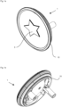
- the Figures 1a and 1b show the operating device 1 according to the invention in an assembled design.
- the assembly shown in this way can be installed in a recess on the vehicle panel, e.g. B. mounted on the tailgate of a vehicle.
- the vehicle emblem 5 is shown in a stylized manner.
- a plate-shaped housing 10 encloses the various components of the assembly according to the invention and offers mounting options on the back, in particular clips and openings for supply lines, for signal lines and supply lines, for the control and evaluation circuit as well as the proximity sensors and the light source.
- the assembly according to the invention shown is compact and includes the functions of proximity detection, the lighting effect for the vehicle emblem and a push button switch.
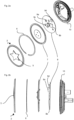
- FIGS. 2a and 2b show the structure of the device according to the invention in respective exploded views.
- cover element 2 Facing the user is a cover element 2, which in this example has a round, transparent cover that has a chrome-plated star emblem 5 in the center.
- cover element 2 is fixed to the light guide element with an annular adhesive element 6 provided with adhesive on both sides.
- the light guide element 7 has a similar design to the cover element 2 itself, but is made of a light guide material with corresponding shapes in order to ensure backlighting of the central element 5.
- the light guide element 7 has a raised light exit surface in the central area, the contour of which lies behind the vehicle emblem 5. In this area, additional light exit points are defined, which provide additional backlighting of the chrome element 5.
- a circuit board 8 is arranged behind the light-guiding element 7.
- This circuit board is supported by the housing structure 10, as already mentioned above with reference to Figures 1a and 1b was shown.
- the housing 10 is used to secure it to the vehicle and to securely hold the circuit board.
- the housing structure is supported on the vehicle and the cover element 2, which is glued to the light guide element 7, can be moved against the housing structure and thus against the circuit board 8 against a spring preload.
- the spring elements are not shown in this design for reasons of clarity.
- Both a capacitive sensor 9b and a surface-mounted LED 9c are arranged on the circuit board 8 the illumination of the light-directing element 7 takes over. Furthermore, a microswitch 9a is arranged on the circuit board, which registers a pressure actuation when the components of the cover plate 2 with the light guide 7 move against the circuit board 8 and trigger the pressure switch 9a in the form of a microswitch.
- the metallized element 5 is obviously galvanically separated from the circuit board by the non-metallized area of the cover element 2, the adhesive layer 6 and the light guide 7.
- the emblem 5 is also separated from the vehicle mass. Nevertheless, the metal surface of the emblem 5 represents a capacitor surface capacitively coupled to the sensor 9b. In this way, the emblem focuses on the detection area of the sensor 9b and allows the sensor to react sensitively to approaches to the element 5.
- a control and evaluation device 9d is coupled to the components 9a, 9b and 9c.
- the illustrated embodiment therefore provides an actuation device which backlights a vehicle emblem or vehicle logo (or manufacturer's logo) and offers the user a clearly localizable and easy-to-operate device.
- the user can perform both a pressure operation and a proximity operation, registered by the proximity sensor 9b.
- the control and evaluation device 9a controls the light source 9c depending on the operations.
- the light source 9c can therefore be controlled depending on the mechanical actuation, which is sensed by the pressure switch 9a, and also by the proximity detection by sensor 9b.
- the control and evaluation circuit 9d can give feedback to the user via the light source 9c in order to guide him to adhere to a specific usage pattern. For example, the user may be required to carry out an operation in the form of moving closer or further away from a part of the body within a period of time that is made visible by a light signal.
- actuating device 1 further components can also be included in the actuating device 1.
- cover device with a partially metallized emblem is provided and that the cover device can be backlit with a light distribution device, where the lighting is controlled by a control and evaluation device.
- the combination with a proximity sensor then offers the above-mentioned advantages of an integrated actuation device with a user-friendly actuation option.
Landscapes
- Lighting Device Outwards From Vehicle And Optical Signal (AREA)
- Vehicle Waterproofing, Decoration, And Sanitation Devices (AREA)
- Illuminated Signs And Luminous Advertising (AREA)
Claims (4)
- Dispositif d'actionnement (1) pour actionner une fonction du véhicule, comprenantun élément de couvercle (2), l'élément de couvercle (2) présentant une zone de commande (5) orientée vers l'extérieur et réalisée au moins partiellement en un matériau métallique électriquement conducteur, la zone de commande étant découplée galvaniquement des autres composants,un dispositif de répartition de lumière (7) avec une source de lumière (9c) disposée sous ou dans le dispositif de répartition de lumière étant disposé sous l'élément de couvercle (2), la source de lumière (9c) et le dispositif de répartition de lumière (7) étant disposés pour le rétroéclairage de l'élément de couvercle (2),dans lequel le dispositif de répartition de la lumière (7) est réalisé en une matière plastique transparente électriquement isolante et il découple galvaniquement l'élément de couvercle (2) des autres éléments,une platine (8) avec un capteur capacitif (9b) étant disposée sous le dispositif de répartition de lumière (7) de telle sorte que le capteur capacitif est couplé de manière capacitive avec la zone de commande (5),un circuit de commande et d'évaluation (9d) étant couplé à la source lumineuse (9c) et au capteur capacitif (9b) afin de commuter la source lumineuse en fonction d'une approche,caractériséen ce qu'un interrupteur (9a) est disposé sur la platine (8) en dessous de l'élément de couvercle (2) et que l'élément de couvercle (2) est disposé de manière mobile par rapport à l'interrupteur, de sorte qu'un actionnement de l'interrupteur est effectué par une action mécanique sur l'élément de couvercle (2).
- Dispositif d'actionnement selon la revendication 1, dans lequel l'élément de couvercle présente une face frontale partiellement opaque et dans lequel le dispositif de répartition de la lumière est conçu pour éclairer les zones transparentes de l'élément de couvercle.
- Dispositif d'actionnement selon l'une quelconque des revendications précédentes, dans lequel le dispositif de répartition de la lumière comprend des zones de guidage de la lumière pour guider et diriger la lumière provenant de la source de lumière.
- Dispositif d'actionnement selon l'une quelconque des revendications précédentes, dans lequel le dispositif de répartition de la lumière comprend des zones de diffusion pour diffuser la lumière provenant de la source lumineuse.
Applications Claiming Priority (2)
| Application Number | Priority Date | Filing Date | Title |
|---|---|---|---|
| DE102014100698.4A DE102014100698A1 (de) | 2014-01-22 | 2014-01-22 | Betätigungseinrichtung für ein Kraftfahrzeug |
| PCT/EP2014/078667 WO2015110239A1 (fr) | 2014-01-22 | 2014-12-19 | Dispositif actionneur pour véhicule à moteur |
Publications (2)
| Publication Number | Publication Date |
|---|---|
| EP3097642A1 EP3097642A1 (fr) | 2016-11-30 |
| EP3097642B1 true EP3097642B1 (fr) | 2023-09-27 |
Family
ID=52354926
Family Applications (1)
| Application Number | Title | Priority Date | Filing Date |
|---|---|---|---|
| EP14827745.2A Active EP3097642B1 (fr) | 2014-01-22 | 2014-12-19 | Dispositif actionneur pour véhicule à moteur |
Country Status (5)
| Country | Link |
|---|---|
| US (1) | US10164630B2 (fr) |
| EP (1) | EP3097642B1 (fr) |
| CN (1) | CN106416074A (fr) |
| DE (1) | DE102014100698A1 (fr) |
| WO (1) | WO2015110239A1 (fr) |
Cited By (1)
| Publication number | Priority date | Publication date | Assignee | Title |
|---|---|---|---|---|
| WO2026012638A1 (fr) * | 2024-07-09 | 2026-01-15 | Huf Hülsbeck & Fürst Gmbh & Co. Kg | Dispositif d'actionnement pour un système d'accès d'un véhicule, pour actionner une partie mobile du véhicule |
Families Citing this family (15)
| Publication number | Priority date | Publication date | Assignee | Title |
|---|---|---|---|---|
| WO2018013557A1 (fr) | 2016-07-11 | 2018-01-18 | Shanghai Yanfeng Jinqiao Automotive Trim Systems Co. Ltd | Élément d'intérieur de véhicule |
| US20180265043A1 (en) * | 2017-03-14 | 2018-09-20 | Ford Global Technologies, Llc | Proximity switch and humidity sensor assembly |
| US10023110B1 (en) * | 2017-04-21 | 2018-07-17 | Ford Global Technologies, Llc | Vehicle badge sensor assembly |
| DE102017127224A1 (de) | 2017-11-20 | 2019-05-23 | Valeo Schalter Und Sensoren Gmbh | Näherungsdetektion mittels Bedienfeld |
| US10203084B1 (en) * | 2017-12-11 | 2019-02-12 | Ecolink Intelligent Technology, Inc. | Illumination feature for electronic devices |
| EP3824376B1 (fr) | 2018-07-18 | 2025-04-09 | Shanghai Yanfeng Jinqiao Automotive Trim Systems Co. Ltd | Pièce d'intérieur de véhicule |
| DE102019007410A1 (de) * | 2018-10-30 | 2020-04-30 | Marquardt Gmbh | Schaltelement |
| DE102019202259A1 (de) * | 2019-02-20 | 2020-08-20 | Psa Automobiles Sa | Betätigungseinrichtung für den Kraftfahrzeugaußenbereich |
| WO2021011536A1 (fr) | 2019-07-15 | 2021-01-21 | Shanghai Yanfeng Jinqiao Automotive Trim Systems Co. Ltd. | Composant intérieur de véhicule |
| US11927671B2 (en) * | 2020-06-23 | 2024-03-12 | Audio Authority Corporation | Touchless sensor and method of retrofitting a touchless sensor into push-button receiver |
| FR3111656B1 (fr) * | 2020-06-23 | 2022-06-17 | Vitesco Technologies | Dispositif d’ouverture/fermeture d’ouvrant par détection de mouvement d’un membre d’utilisateur et procédé d’ouverture/fermeture associé |
| US11203281B1 (en) * | 2020-09-21 | 2021-12-21 | Ford Global Technologies, Llc | Visible light manipulating emblem for a vehicle |
| WO2022189487A1 (fr) * | 2021-03-10 | 2022-09-15 | Huf Hülsbeck & Fürst Gmbh & Co. Kg | Composant modulaire pour une partie mobile d'un véhicule et procédé de fabrication d'un composant modulaire |
| DE102022119083B4 (de) * | 2022-07-29 | 2025-10-23 | Bayerische Motoren Werke Aktiengesellschaft | Verkleidungsanordnung eines mit einem Stauraum ausgestatteten Vorderwagens eines Personenkraftwagens und Betätigungsverfahren |
| DE102025000377B3 (de) | 2025-01-31 | 2026-01-08 | Mercedes-Benz Group AG | Beleuchtungsvorrichtung für ein Kraftfahrzeug |
Citations (4)
| Publication number | Priority date | Publication date | Assignee | Title |
|---|---|---|---|---|
| DE202005013420U1 (de) * | 2004-09-01 | 2005-11-17 | E.G.O. Control Systems Gmbh | Sensorvorrichtung |
| FR2933825A1 (fr) * | 2008-07-10 | 2010-01-15 | Peugeot Citroen Automobiles Sa | Dispositif de controle de fonction(s) d'equipement(s) par detection de variation de capacite |
| WO2011063377A1 (fr) * | 2009-11-23 | 2011-05-26 | Touchsensor Technologies, Llc | Panneau d'interface utilisateur |
| DE102011088653A1 (de) * | 2011-12-15 | 2013-06-20 | BSH Bosch und Siemens Hausgeräte GmbH | Bedienfeld für ein Elektrogerät |
Family Cites Families (35)
| Publication number | Priority date | Publication date | Assignee | Title |
|---|---|---|---|---|
| US6774505B1 (en) | 1998-07-17 | 2004-08-10 | Lear Automotive Dearborn, Inc. | Vehicle switch assembly with proximity activated illumination |
| US7370983B2 (en) * | 2000-03-02 | 2008-05-13 | Donnelly Corporation | Interior mirror assembly with display |
| DE102004024263A1 (de) | 2003-08-08 | 2005-03-24 | Daimlerchrysler Ag | Beleuchtetes Logo |
| US7576631B1 (en) * | 2004-10-26 | 2009-08-18 | Adac Plastics, Inc. | Vehicular keyless entry system incorporating textual representation of the vehicle or user of the vehicle |
| DE102004060846B4 (de) * | 2004-12-17 | 2008-12-18 | Diehl Ako Stiftung & Co. Kg | Kapazitiver Berührungsschalter |
| US20060226953A1 (en) * | 2005-04-07 | 2006-10-12 | Honeywell International Inc. | Passive entry sensor system |
| DE502006009331D1 (de) * | 2005-08-19 | 2011-06-01 | Ego Control Systems Gmbh | Sensorvorrichtung |
| DE102006003174A1 (de) * | 2006-01-23 | 2007-07-26 | Siemens Ag | Bedienelement |
| US8866750B2 (en) * | 2006-04-10 | 2014-10-21 | Microsoft Corporation | Universal user interface device |
| DE102007010328A1 (de) | 2006-10-12 | 2008-04-17 | Trw Automotive Safety Systems Gmbh | Baugruppe zur beleuchteten Darstellung eines Logos |
| DE102007050654B4 (de) * | 2007-10-24 | 2015-06-18 | Diehl Ako Stiftung & Co. Kg | Kapazitiver Berührungsschalter |
| US8154418B2 (en) * | 2008-03-31 | 2012-04-10 | Magna Mirrors Of America, Inc. | Interior rearview mirror system |
| DE102008029567A1 (de) | 2008-06-21 | 2010-01-07 | Preh Gmbh | Beleuchteter kapazitiver Annäherungssensor |
| US20100007463A1 (en) * | 2008-07-09 | 2010-01-14 | Magna Mirrors Of America, Inc. | Vehicle handle with control circuitry |
| DE102009007707A1 (de) | 2009-02-05 | 2010-08-12 | Daimler Ag | Bedienvorrichtung zur Steuerung elektrisch verstellbarer Komponenten |
| US8326501B2 (en) * | 2009-02-27 | 2012-12-04 | Nissan North America, Inc. | Method and apparatus for shift-by-wire in a motor vehicle |
| DE102009001412B4 (de) * | 2009-03-09 | 2018-10-11 | Volkswagen Ag | Kapazitives Anzeige- und Bedienelement |
| CN106020583B (zh) * | 2009-08-21 | 2019-05-28 | 苹果公司 | 用于电容感测的方法和装置 |
| US9346403B2 (en) * | 2009-10-07 | 2016-05-24 | Magna Mirrors Of America, Inc. | Rearview mirror assembly |
| DE102010010574B4 (de) * | 2010-03-08 | 2024-06-06 | Volkswagen Ag | Bedienvorrichtung für ein Fahrzeug |
| JP5573374B2 (ja) | 2010-06-03 | 2014-08-20 | ソニー株式会社 | 情報処理装置および操作入力方法 |
| US9780781B2 (en) * | 2010-09-28 | 2017-10-03 | Blackberry Limited | Multi-action capacitive switch and methods of use |
| US8552746B2 (en) * | 2010-12-22 | 2013-10-08 | Visteon Global Technologies, Inc. | Proximity sensor including a multilayer elastomer assembly |
| JP2013077555A (ja) | 2011-09-12 | 2013-04-25 | Futaba Corp | タッチスイッチ |
| US9559688B2 (en) * | 2012-04-11 | 2017-01-31 | Ford Global Technologies, Llc | Proximity switch assembly having pliable surface and depression |
| US9524633B2 (en) * | 2013-03-14 | 2016-12-20 | Lutron Electronics Co., Inc. | Remote control having a capacitive touch surface and a mechanism for awakening the remote control |
| US9568524B2 (en) * | 2013-05-29 | 2017-02-14 | Atmel Corporation | Multi-state capacitive button |
| US20140368029A1 (en) * | 2013-06-13 | 2014-12-18 | Hyundai Motor Company | System for providing vehicle manipulation device information |
| JP6079469B2 (ja) * | 2013-06-21 | 2017-02-15 | トヨタ紡織株式会社 | 照明付タッチスイッチ装置 |
| DE102013110596A1 (de) * | 2013-09-25 | 2015-04-09 | Huf Hülsbeck & Fürst Gmbh & Co. Kg | Baugruppe für Betätigung einer Fahrzeugfunktion |
| US9539939B2 (en) * | 2013-11-21 | 2017-01-10 | Ford Global Technologies, Llc | Photoluminescent logo for vehicle trim and fabric |
| JP2015122141A (ja) * | 2013-12-20 | 2015-07-02 | アイシン精機株式会社 | 静電容量センサ電極 |
| US20150277620A1 (en) * | 2014-03-31 | 2015-10-01 | Synaptics Incorporated | Methods and apparatus for capacitive force sensing on keyboard keys using a compressible dielectric |
| US9694735B2 (en) * | 2015-01-26 | 2017-07-04 | Flextronics International Usa, Inc. | Vehicle emblem incorporating capacitive switch and LED lighting |
| US10026721B2 (en) * | 2015-06-30 | 2018-07-17 | Apple Inc. | Electronic devices with soft input-output components |
-
2014
- 2014-01-22 DE DE102014100698.4A patent/DE102014100698A1/de not_active Withdrawn
- 2014-12-19 CN CN201480073952.4A patent/CN106416074A/zh active Pending
- 2014-12-19 WO PCT/EP2014/078667 patent/WO2015110239A1/fr not_active Ceased
- 2014-12-19 EP EP14827745.2A patent/EP3097642B1/fr active Active
- 2014-12-19 US US15/112,139 patent/US10164630B2/en not_active Expired - Fee Related
Patent Citations (4)
| Publication number | Priority date | Publication date | Assignee | Title |
|---|---|---|---|---|
| DE202005013420U1 (de) * | 2004-09-01 | 2005-11-17 | E.G.O. Control Systems Gmbh | Sensorvorrichtung |
| FR2933825A1 (fr) * | 2008-07-10 | 2010-01-15 | Peugeot Citroen Automobiles Sa | Dispositif de controle de fonction(s) d'equipement(s) par detection de variation de capacite |
| WO2011063377A1 (fr) * | 2009-11-23 | 2011-05-26 | Touchsensor Technologies, Llc | Panneau d'interface utilisateur |
| DE102011088653A1 (de) * | 2011-12-15 | 2013-06-20 | BSH Bosch und Siemens Hausgeräte GmbH | Bedienfeld für ein Elektrogerät |
Cited By (1)
| Publication number | Priority date | Publication date | Assignee | Title |
|---|---|---|---|---|
| WO2026012638A1 (fr) * | 2024-07-09 | 2026-01-15 | Huf Hülsbeck & Fürst Gmbh & Co. Kg | Dispositif d'actionnement pour un système d'accès d'un véhicule, pour actionner une partie mobile du véhicule |
Also Published As
| Publication number | Publication date |
|---|---|
| US10164630B2 (en) | 2018-12-25 |
| WO2015110239A1 (fr) | 2015-07-30 |
| CN106416074A (zh) | 2017-02-15 |
| US20160329894A1 (en) | 2016-11-10 |
| EP3097642A1 (fr) | 2016-11-30 |
| DE102014100698A1 (de) | 2015-07-23 |
Similar Documents
| Publication | Publication Date | Title |
|---|---|---|
| EP3097642B1 (fr) | Dispositif actionneur pour véhicule à moteur | |
| EP3049288B1 (fr) | Ensemble pour faire fonctionner une fonction de véhicule | |
| EP1257057B1 (fr) | Elément capteur pour un commutateur capacitif à effleurement | |
| EP1573111B1 (fr) | Appareil electromenager equipe d'un dispositif de commande et d'un dispositif d'affichage | |
| DE102009033538A1 (de) | Bedieneinrichtung für ein Elektrogerät | |
| EP3054069B1 (fr) | Système de poignée de porte de véhicule | |
| DE102012010321A1 (de) | Sensorelementeinrichtung für einen kapazitiven Berührungsschalter einer Bedieneinrichtung,Bedieneinrichtung und Kochfeld | |
| DE102007050654A1 (de) | Kapazitiver Berührungsschalter | |
| EP3724019B1 (fr) | Éclairage linéaire muni d'un élément de commande intégré | |
| DE20119700U1 (de) | Sensorvorrichtung | |
| DE102017218243B3 (de) | Verfahren zum Herstellen zumindest eines Teils einer berührungssensitiven Bedieneinrichtung, berührungssensitive Bedieneinrichtung und Kraftfahrzeug | |
| EP1903284B1 (fr) | Dispositif pour appareil ménager et son utilisation | |
| EP3287063B1 (fr) | Appareil électrique, système d'appareil électrique doté d'un écran et procédé de fabrication d'un tel dispositif | |
| DE102017009377A1 (de) | Bedienvorrichtung, insbesondere für ein elektronisches Haushaltsgerät | |
| DE102010024592B4 (de) | Zierteil mit Infrarot-Sensorik | |
| DE10320548B4 (de) | Berührungsschalteinrichtung | |
| WO2018234361A1 (fr) | Dispositif de commande de véhicule automobile et procédé de fabrication d'un dispositif de commande de véhicule automobile | |
| EP3549824B1 (fr) | Dispositif d'éclairage permettant d'éclairer un habitacle d'un véhicule | |
| DE102017212447B4 (de) | Bedienvorrichtung für ein Kraftfahrzeug und Kraftfahrzeug | |
| DE102014019439B4 (de) | Verkleidungsvorrichtung für ein Kraftfahrzeug und Kraftfahrzeug | |
| EP4707682A2 (fr) | Interface utilisateur pour un dispositif de commande d'un système de plaque de cuisson | |
| DE102019008374B3 (de) | Bedienfeld eines Kraftfahrzeugs und zugehöriges Kraftfahrzeug | |
| DE102010036237B4 (de) | Kapazitiver Berührungs- und/oder Annäherungsschalter | |
| DE102017207388A1 (de) | Tragbares Bedienelement mit zumindest zwei separaten Platinen, sowie Bedienvorrichtung | |
| DE202013104425U1 (de) | Bedieneinheit für einen Industrie-Computer mit kombinierter Gesten- und Tastenfeldsteuerung sowie Industrie-Computer damit |
Legal Events
| Date | Code | Title | Description |
|---|---|---|---|
| PUAI | Public reference made under article 153(3) epc to a published international application that has entered the european phase |
Free format text: ORIGINAL CODE: 0009012 |
|
| 17P | Request for examination filed |
Effective date: 20160822 |
|
| AK | Designated contracting states |
Kind code of ref document: A1 Designated state(s): AL AT BE BG CH CY CZ DE DK EE ES FI FR GB GR HR HU IE IS IT LI LT LU LV MC MK MT NL NO PL PT RO RS SE SI SK SM TR |
|
| AX | Request for extension of the european patent |
Extension state: BA ME |
|
| RIN1 | Information on inventor provided before grant (corrected) |
Inventor name: BUSCHMANN, GERD Inventor name: KLAMETH, MARKUS Inventor name: VAN GASTEL, PETER Inventor name: METZNER, THOMAS |
|
| DAX | Request for extension of the european patent (deleted) | ||
| STAA | Information on the status of an ep patent application or granted ep patent |
Free format text: STATUS: EXAMINATION IS IN PROGRESS |
|
| 17Q | First examination report despatched |
Effective date: 20190925 |
|
| GRAP | Despatch of communication of intention to grant a patent |
Free format text: ORIGINAL CODE: EPIDOSNIGR1 |
|
| STAA | Information on the status of an ep patent application or granted ep patent |
Free format text: STATUS: GRANT OF PATENT IS INTENDED |
|
| INTG | Intention to grant announced |
Effective date: 20230615 |
|
| GRAS | Grant fee paid |
Free format text: ORIGINAL CODE: EPIDOSNIGR3 |
|
| P01 | Opt-out of the competence of the unified patent court (upc) registered |
Effective date: 20230717 |
|
| GRAA | (expected) grant |
Free format text: ORIGINAL CODE: 0009210 |
|
| STAA | Information on the status of an ep patent application or granted ep patent |
Free format text: STATUS: THE PATENT HAS BEEN GRANTED |
|
| AK | Designated contracting states |
Kind code of ref document: B1 Designated state(s): AL AT BE BG CH CY CZ DE DK EE ES FI FR GB GR HR HU IE IS IT LI LT LU LV MC MK MT NL NO PL PT RO RS SE SI SK SM TR |
|
| REG | Reference to a national code |
Ref country code: GB Ref legal event code: FG4D Free format text: NOT ENGLISH |
|
| REG | Reference to a national code |
Ref country code: CH Ref legal event code: EP |
|
| REG | Reference to a national code |
Ref country code: DE Ref legal event code: R096 Ref document number: 502014016691 Country of ref document: DE |
|
| REG | Reference to a national code |
Ref country code: IE Ref legal event code: FG4D Free format text: LANGUAGE OF EP DOCUMENT: GERMAN |
|
| REG | Reference to a national code |
Ref country code: LT Ref legal event code: MG9D |
|
| PG25 | Lapsed in a contracting state [announced via postgrant information from national office to epo] |
Ref country code: GR Free format text: LAPSE BECAUSE OF FAILURE TO SUBMIT A TRANSLATION OF THE DESCRIPTION OR TO PAY THE FEE WITHIN THE PRESCRIBED TIME-LIMIT Effective date: 20231228 |
|
| PG25 | Lapsed in a contracting state [announced via postgrant information from national office to epo] |
Ref country code: SE Free format text: LAPSE BECAUSE OF FAILURE TO SUBMIT A TRANSLATION OF THE DESCRIPTION OR TO PAY THE FEE WITHIN THE PRESCRIBED TIME-LIMIT Effective date: 20230927 Ref country code: RS Free format text: LAPSE BECAUSE OF FAILURE TO SUBMIT A TRANSLATION OF THE DESCRIPTION OR TO PAY THE FEE WITHIN THE PRESCRIBED TIME-LIMIT Effective date: 20230927 Ref country code: NO Free format text: LAPSE BECAUSE OF FAILURE TO SUBMIT A TRANSLATION OF THE DESCRIPTION OR TO PAY THE FEE WITHIN THE PRESCRIBED TIME-LIMIT Effective date: 20231227 Ref country code: LV Free format text: LAPSE BECAUSE OF FAILURE TO SUBMIT A TRANSLATION OF THE DESCRIPTION OR TO PAY THE FEE WITHIN THE PRESCRIBED TIME-LIMIT Effective date: 20230927 Ref country code: LT Free format text: LAPSE BECAUSE OF FAILURE TO SUBMIT A TRANSLATION OF THE DESCRIPTION OR TO PAY THE FEE WITHIN THE PRESCRIBED TIME-LIMIT Effective date: 20230927 Ref country code: GR Free format text: LAPSE BECAUSE OF FAILURE TO SUBMIT A TRANSLATION OF THE DESCRIPTION OR TO PAY THE FEE WITHIN THE PRESCRIBED TIME-LIMIT Effective date: 20231228 Ref country code: FI Free format text: LAPSE BECAUSE OF FAILURE TO SUBMIT A TRANSLATION OF THE DESCRIPTION OR TO PAY THE FEE WITHIN THE PRESCRIBED TIME-LIMIT Effective date: 20230927 |
|
| REG | Reference to a national code |
Ref country code: NL Ref legal event code: MP Effective date: 20230927 |
|
| PG25 | Lapsed in a contracting state [announced via postgrant information from national office to epo] |
Ref country code: NL Free format text: LAPSE BECAUSE OF FAILURE TO SUBMIT A TRANSLATION OF THE DESCRIPTION OR TO PAY THE FEE WITHIN THE PRESCRIBED TIME-LIMIT Effective date: 20230927 |
|
| PG25 | Lapsed in a contracting state [announced via postgrant information from national office to epo] |
Ref country code: IS Free format text: LAPSE BECAUSE OF FAILURE TO SUBMIT A TRANSLATION OF THE DESCRIPTION OR TO PAY THE FEE WITHIN THE PRESCRIBED TIME-LIMIT Effective date: 20240127 |
|
| PG25 | Lapsed in a contracting state [announced via postgrant information from national office to epo] |
Ref country code: ES Free format text: LAPSE BECAUSE OF FAILURE TO SUBMIT A TRANSLATION OF THE DESCRIPTION OR TO PAY THE FEE WITHIN THE PRESCRIBED TIME-LIMIT Effective date: 20230927 |
|
| PG25 | Lapsed in a contracting state [announced via postgrant information from national office to epo] |
Ref country code: SM Free format text: LAPSE BECAUSE OF FAILURE TO SUBMIT A TRANSLATION OF THE DESCRIPTION OR TO PAY THE FEE WITHIN THE PRESCRIBED TIME-LIMIT Effective date: 20230927 Ref country code: RO Free format text: LAPSE BECAUSE OF FAILURE TO SUBMIT A TRANSLATION OF THE DESCRIPTION OR TO PAY THE FEE WITHIN THE PRESCRIBED TIME-LIMIT Effective date: 20230927 Ref country code: IS Free format text: LAPSE BECAUSE OF FAILURE TO SUBMIT A TRANSLATION OF THE DESCRIPTION OR TO PAY THE FEE WITHIN THE PRESCRIBED TIME-LIMIT Effective date: 20240127 Ref country code: ES Free format text: LAPSE BECAUSE OF FAILURE TO SUBMIT A TRANSLATION OF THE DESCRIPTION OR TO PAY THE FEE WITHIN THE PRESCRIBED TIME-LIMIT Effective date: 20230927 Ref country code: EE Free format text: LAPSE BECAUSE OF FAILURE TO SUBMIT A TRANSLATION OF THE DESCRIPTION OR TO PAY THE FEE WITHIN THE PRESCRIBED TIME-LIMIT Effective date: 20230927 Ref country code: CZ Free format text: LAPSE BECAUSE OF FAILURE TO SUBMIT A TRANSLATION OF THE DESCRIPTION OR TO PAY THE FEE WITHIN THE PRESCRIBED TIME-LIMIT Effective date: 20230927 Ref country code: PT Free format text: LAPSE BECAUSE OF FAILURE TO SUBMIT A TRANSLATION OF THE DESCRIPTION OR TO PAY THE FEE WITHIN THE PRESCRIBED TIME-LIMIT Effective date: 20240129 Ref country code: SK Free format text: LAPSE BECAUSE OF FAILURE TO SUBMIT A TRANSLATION OF THE DESCRIPTION OR TO PAY THE FEE WITHIN THE PRESCRIBED TIME-LIMIT Effective date: 20230927 |
|
| PG25 | Lapsed in a contracting state [announced via postgrant information from national office to epo] |
Ref country code: PL Free format text: LAPSE BECAUSE OF FAILURE TO SUBMIT A TRANSLATION OF THE DESCRIPTION OR TO PAY THE FEE WITHIN THE PRESCRIBED TIME-LIMIT Effective date: 20230927 Ref country code: IT Free format text: LAPSE BECAUSE OF FAILURE TO SUBMIT A TRANSLATION OF THE DESCRIPTION OR TO PAY THE FEE WITHIN THE PRESCRIBED TIME-LIMIT Effective date: 20230927 |
|
| REG | Reference to a national code |
Ref country code: DE Ref legal event code: R097 Ref document number: 502014016691 Country of ref document: DE |
|
| PG25 | Lapsed in a contracting state [announced via postgrant information from national office to epo] |
Ref country code: DK Free format text: LAPSE BECAUSE OF FAILURE TO SUBMIT A TRANSLATION OF THE DESCRIPTION OR TO PAY THE FEE WITHIN THE PRESCRIBED TIME-LIMIT Effective date: 20230927 |
|
| PG25 | Lapsed in a contracting state [announced via postgrant information from national office to epo] |
Ref country code: DK Free format text: LAPSE BECAUSE OF FAILURE TO SUBMIT A TRANSLATION OF THE DESCRIPTION OR TO PAY THE FEE WITHIN THE PRESCRIBED TIME-LIMIT Effective date: 20230927 |
|
| REG | Reference to a national code |
Ref country code: CH Ref legal event code: PL |
|
| PLBE | No opposition filed within time limit |
Free format text: ORIGINAL CODE: 0009261 |
|
| STAA | Information on the status of an ep patent application or granted ep patent |
Free format text: STATUS: NO OPPOSITION FILED WITHIN TIME LIMIT |
|
| PG25 | Lapsed in a contracting state [announced via postgrant information from national office to epo] |
Ref country code: LU Free format text: LAPSE BECAUSE OF NON-PAYMENT OF DUE FEES Effective date: 20231219 |
|
| PG25 | Lapsed in a contracting state [announced via postgrant information from national office to epo] |
Ref country code: MC Free format text: LAPSE BECAUSE OF FAILURE TO SUBMIT A TRANSLATION OF THE DESCRIPTION OR TO PAY THE FEE WITHIN THE PRESCRIBED TIME-LIMIT Effective date: 20230927 |
|
| GBPC | Gb: european patent ceased through non-payment of renewal fee |
Effective date: 20231227 |
|
| REG | Reference to a national code |
Ref country code: BE Ref legal event code: MM Effective date: 20231231 |
|
| PG25 | Lapsed in a contracting state [announced via postgrant information from national office to epo] |
Ref country code: MC Free format text: LAPSE BECAUSE OF FAILURE TO SUBMIT A TRANSLATION OF THE DESCRIPTION OR TO PAY THE FEE WITHIN THE PRESCRIBED TIME-LIMIT Effective date: 20230927 Ref country code: LU Free format text: LAPSE BECAUSE OF NON-PAYMENT OF DUE FEES Effective date: 20231219 |
|
| 26N | No opposition filed |
Effective date: 20240628 |
|
| REG | Reference to a national code |
Ref country code: IE Ref legal event code: MM4A |
|
| PG25 | Lapsed in a contracting state [announced via postgrant information from national office to epo] |
Ref country code: IE Free format text: LAPSE BECAUSE OF NON-PAYMENT OF DUE FEES Effective date: 20231219 |
|
| PG25 | Lapsed in a contracting state [announced via postgrant information from national office to epo] |
Ref country code: GB Free format text: LAPSE BECAUSE OF NON-PAYMENT OF DUE FEES Effective date: 20231227 |
|
| PG25 | Lapsed in a contracting state [announced via postgrant information from national office to epo] |
Ref country code: BE Free format text: LAPSE BECAUSE OF NON-PAYMENT OF DUE FEES Effective date: 20231231 |
|
| PG25 | Lapsed in a contracting state [announced via postgrant information from national office to epo] |
Ref country code: FR Free format text: LAPSE BECAUSE OF NON-PAYMENT OF DUE FEES Effective date: 20231231 |
|
| PG25 | Lapsed in a contracting state [announced via postgrant information from national office to epo] |
Ref country code: CH Free format text: LAPSE BECAUSE OF NON-PAYMENT OF DUE FEES Effective date: 20231231 |
|
| PG25 | Lapsed in a contracting state [announced via postgrant information from national office to epo] |
Ref country code: SI Free format text: LAPSE BECAUSE OF FAILURE TO SUBMIT A TRANSLATION OF THE DESCRIPTION OR TO PAY THE FEE WITHIN THE PRESCRIBED TIME-LIMIT Effective date: 20230927 |
|
| PG25 | Lapsed in a contracting state [announced via postgrant information from national office to epo] |
Ref country code: SI Free format text: LAPSE BECAUSE OF FAILURE TO SUBMIT A TRANSLATION OF THE DESCRIPTION OR TO PAY THE FEE WITHIN THE PRESCRIBED TIME-LIMIT Effective date: 20230927 Ref country code: IE Free format text: LAPSE BECAUSE OF NON-PAYMENT OF DUE FEES Effective date: 20231219 Ref country code: GB Free format text: LAPSE BECAUSE OF NON-PAYMENT OF DUE FEES Effective date: 20231227 Ref country code: FR Free format text: LAPSE BECAUSE OF NON-PAYMENT OF DUE FEES Effective date: 20231231 Ref country code: CH Free format text: LAPSE BECAUSE OF NON-PAYMENT OF DUE FEES Effective date: 20231231 Ref country code: BE Free format text: LAPSE BECAUSE OF NON-PAYMENT OF DUE FEES Effective date: 20231231 |
|
| PG25 | Lapsed in a contracting state [announced via postgrant information from national office to epo] |
Ref country code: BG Free format text: LAPSE BECAUSE OF FAILURE TO SUBMIT A TRANSLATION OF THE DESCRIPTION OR TO PAY THE FEE WITHIN THE PRESCRIBED TIME-LIMIT Effective date: 20230927 |
|
| PG25 | Lapsed in a contracting state [announced via postgrant information from national office to epo] |
Ref country code: BG Free format text: LAPSE BECAUSE OF FAILURE TO SUBMIT A TRANSLATION OF THE DESCRIPTION OR TO PAY THE FEE WITHIN THE PRESCRIBED TIME-LIMIT Effective date: 20230927 |
|
| REG | Reference to a national code |
Ref country code: AT Ref legal event code: MM01 Ref document number: 1616407 Country of ref document: AT Kind code of ref document: T Effective date: 20231219 |
|
| PG25 | Lapsed in a contracting state [announced via postgrant information from national office to epo] |
Ref country code: HR Free format text: LAPSE BECAUSE OF FAILURE TO SUBMIT A TRANSLATION OF THE DESCRIPTION OR TO PAY THE FEE WITHIN THE PRESCRIBED TIME-LIMIT Effective date: 20230927 |
|
| PG25 | Lapsed in a contracting state [announced via postgrant information from national office to epo] |
Ref country code: AT Free format text: LAPSE BECAUSE OF NON-PAYMENT OF DUE FEES Effective date: 20231219 |
|
| PG25 | Lapsed in a contracting state [announced via postgrant information from national office to epo] |
Ref country code: CY Free format text: LAPSE BECAUSE OF FAILURE TO SUBMIT A TRANSLATION OF THE DESCRIPTION OR TO PAY THE FEE WITHIN THE PRESCRIBED TIME-LIMIT; INVALID AB INITIO Effective date: 20141219 |
|
| PG25 | Lapsed in a contracting state [announced via postgrant information from national office to epo] |
Ref country code: HU Free format text: LAPSE BECAUSE OF FAILURE TO SUBMIT A TRANSLATION OF THE DESCRIPTION OR TO PAY THE FEE WITHIN THE PRESCRIBED TIME-LIMIT; INVALID AB INITIO Effective date: 20141219 |
|
| PG25 | Lapsed in a contracting state [announced via postgrant information from national office to epo] |
Ref country code: TR Free format text: LAPSE BECAUSE OF FAILURE TO SUBMIT A TRANSLATION OF THE DESCRIPTION OR TO PAY THE FEE WITHIN THE PRESCRIBED TIME-LIMIT Effective date: 20230927 |
|
| PGFP | Annual fee paid to national office [announced via postgrant information from national office to epo] |
Ref country code: DE Payment date: 20251231 Year of fee payment: 12 |