EP3097895A1 - Verfahren zur herstellung nicht verbundener faserstrukturen - Google Patents
Verfahren zur herstellung nicht verbundener faserstrukturen Download PDFInfo
- Publication number
- EP3097895A1 EP3097895A1 EP16170631.2A EP16170631A EP3097895A1 EP 3097895 A1 EP3097895 A1 EP 3097895A1 EP 16170631 A EP16170631 A EP 16170631A EP 3097895 A1 EP3097895 A1 EP 3097895A1
- Authority
- EP
- European Patent Office
- Prior art keywords
- shell
- speed
- fibrous
- mover
- carrier
- Prior art date
- Legal status (The legal status is an assumption and is not a legal conclusion. Google has not performed a legal analysis and makes no representation as to the accuracy of the status listed.)
- Granted
Links
Images

Classifications
-
- A—HUMAN NECESSITIES
- A61—MEDICAL OR VETERINARY SCIENCE; HYGIENE
- A61F—FILTERS IMPLANTABLE INTO BLOOD VESSELS; PROSTHESES; DEVICES PROVIDING PATENCY TO, OR PREVENTING COLLAPSING OF, TUBULAR STRUCTURES OF THE BODY, e.g. STENTS; ORTHOPAEDIC, NURSING OR CONTRACEPTIVE DEVICES; FOMENTATION; TREATMENT OR PROTECTION OF EYES OR EARS; BANDAGES, DRESSINGS OR ABSORBENT PADS; FIRST-AID KITS
- A61F13/00—Bandages or dressings; Absorbent pads
- A61F13/15—Absorbent pads, e.g. sanitary towels, swabs or tampons for external or internal application to the body; Supporting or fastening means therefor; Tampon applicators
- A61F13/15577—Apparatus or processes for manufacturing
- A61F13/15617—Making absorbent pads from fibres or pulverulent material with or without treatment of the fibres
- A61F13/15634—Making fibrous pads between sheets or webs
-
- B—PERFORMING OPERATIONS; TRANSPORTING
- B29—WORKING OF PLASTICS; WORKING OF SUBSTANCES IN A PLASTIC STATE IN GENERAL
- B29C—SHAPING OR JOINING OF PLASTICS; SHAPING OF MATERIAL IN A PLASTIC STATE, NOT OTHERWISE PROVIDED FOR; AFTER-TREATMENT OF THE SHAPED PRODUCTS, e.g. REPAIRING
- B29C65/00—Joining or sealing of preformed parts, e.g. welding of plastics materials; Apparatus therefor
- B29C65/76—Making non-permanent or releasable joints
-
- A—HUMAN NECESSITIES
- A61—MEDICAL OR VETERINARY SCIENCE; HYGIENE
- A61F—FILTERS IMPLANTABLE INTO BLOOD VESSELS; PROSTHESES; DEVICES PROVIDING PATENCY TO, OR PREVENTING COLLAPSING OF, TUBULAR STRUCTURES OF THE BODY, e.g. STENTS; ORTHOPAEDIC, NURSING OR CONTRACEPTIVE DEVICES; FOMENTATION; TREATMENT OR PROTECTION OF EYES OR EARS; BANDAGES, DRESSINGS OR ABSORBENT PADS; FIRST-AID KITS
- A61F13/00—Bandages or dressings; Absorbent pads
- A61F13/15—Absorbent pads, e.g. sanitary towels, swabs or tampons for external or internal application to the body; Supporting or fastening means therefor; Tampon applicators
- A61F13/15577—Apparatus or processes for manufacturing
- A61F13/15764—Transferring, feeding or handling devices; Drives
-
- B—PERFORMING OPERATIONS; TRANSPORTING
- B29—WORKING OF PLASTICS; WORKING OF SUBSTANCES IN A PLASTIC STATE IN GENERAL
- B29L—INDEXING SCHEME ASSOCIATED WITH SUBCLASS B29C, RELATING TO PARTICULAR ARTICLES
- B29L2009/00—Layered products
Definitions
- Fibrous structures may be either consolidated, bonded webs, such as nonwoven webs, but can also be unbonded structures, often made of natural fibers such as cellulose fibers or chemically modified cellulose fibers.
- Unbonded fibrous structures can for example be used as absorbent cores, wherein the fibers are typically mixed with superabsorbent gelling materials, such as superabsorbent polymer particles. Moreover, such unbonded fibrous structures can be used in so-called liquid acquisition systems overlaying the absorbent core.
- unbonded fibrous webs are typically formed on relatively large diameter drums.
- Such drums enable a variety of different sized fibrous webs to be manufactured on the same drum diameter, but at different patch lengths and different pitch.
- a smaller drum would be more energy efficient, and would enable more efficient use of space.
- the present invention relates to a method for forming and transferring an unbonded fibrous structure to a carrier, the method comprising the steps of:
- Programmable servomotors have been used in manufacturing processes and offer, amongst other advantages, the possibility to position individual components relative to one another, and to accelerate or decelerate the speed of individual components in the process.
- Rotary and linear programmable servomotor systems are known.
- WO2013/143728 and WO2013/143783 both published on October 3 rd 2013, describe a linear transport system comprising a stator device and a position detection device for detecting a position of a movable element in a drive device.
- the manufacturer Beckhoff Automation GmbH, markets such a system under the name “eXtended Transport System", or XTS.
- XTS Extended Transport System
- Rockwell Automation which is marketed under the name "i-Trac”.
- the present invention applies the principle of programmable servomotors to the method of forming unbonded fibrous structures, such as patches of fibrous material, and transferring the fibrous patch to a carrier, preferably a carrier web.
- Unbonded fibrous structures have no inherent strength or integrity and hence cannot be formed using existing process technology such as disclosed in US 6,811,019 .
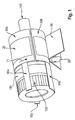
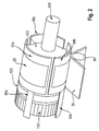
- FIG. 1-3 depicts a non-limiting exemplary embodiment of the method for receiving fibrous material on a shell travelling at a first speed through a receiving zone 23 in a direction indicated by arrow 21, forming on the shell a fibrous patch 25 from the fibrous material, and then applying the fibrous patch 25 to a carrier 30 traveling at a second speed in a direction indicated by arrow 31.
- Carrier 30 may include, but is not limited to, a web substrate, belt, drum, and external-discrete part.
- shells 50a-c are used, however, one skilled in the art would appreciate that any reasonable number of multiple shells may be used.
- Shells 50a-c are adjoined to a corresponding programmable motor by means of movers 60a-c that transport said shell along a stationary track 100 in a direction as indicated by arrow 71.
- shells 50a-c have an axial length from about 4 cm to about 200 cm, tangential width from about 0.5 cm to about 200 cm, and a thickness from about 0.25 mm to about 300 mm.
- Shells 50a-c may be constructed of plastic, aluminum, steel, fibre reinforced composites, such as carbon fibre or glass fibre reinforced composites, and combinations thereof; although one skilled in the art would appreciate that other suitable materials may be used.
- the dimensions of the shell 50 may vary depending upon the desired output of the apparatus 10 and the size and shape of the discrete patches 25 being transferred.
- the shells 50 are driven around a stationary track 100 by a motor which comprises movers 60 and stator 103.
- the stator comprises programmable magnets.
- the shells 50 travel in the direction indicated by the arrow 71 as shown in FIG. 1 .
- the circumferential, outer peripheral surface of the shell 50 defined by an outer radius travels along and defines a path (e.g.
- each shell 50 may have an outer peripheral arc length which spans from about 2 to about 115 degrees of the orbital path.
- the use of a programmable motor in apparatus 10 provides an inexpensive and adaptable method for forming patches 25 at a speed and applying the patches 25 to a carrier 30 traveling at a different speed.
- the variable angular velocity of movers 60 is produced by varying the current supplied to electromagnets. Since the shell 50 is coupled to the output of the motor 60, changes in the angular velocity and position of the movers 60a-c directly correlate to changes in the angular velocity and position of shell 50.
- the current supplied to the electromagnets can be controlled using any of a variety of a methods for programming motors known to those skilled in the art such as, standard cam curve functions, a reference data table containing reference points, desired motor encoder points, and the like or combinations thereof.
- the means of supplying the rotational movement required can be achieved in a plurality of methods to those skilled in the art.
- the programmable electric motors can be driven from any known power source that is capable of delivering a modulated signal such that the motor torque can be varied proportionally.
- One or more power sources deliver a modulated torque signal.
- the torque signal is typically an electrical current which may be fed to the individual electromagnets by separate power supplies or by a single power supply and controlled by a plurality of methods to those skilled in the art.
- the use of programmable motors provides the ability to obtain greater changes in speed and to maintain constant speeds for a fixed duration.
- the fixed speed dwell achieved by programmable motors can be accurately and quickly generated to control the length and placement of the parts.
- the use of programmable motors provides the ability to change the profile at will without requiring the fabrication of new parts.
- the actual position of the shell 50 can be controlled by a plurality of methods known to those skilled in the art including, but not limited to, a position transducer (e.g., encoder-based system, resolver-based system, etc).
- a position transducer e.g., encoder-based system, resolver-based system, etc.
- the actual position of the shell 50 can be controlled by a programmable system that incorporates a position feedback from the shell 50 and mover 60.
- the actual position may not be needed if the position of the shell 50 can be inferred by other means known to those skilled in the art.
- the control method may be used to provide the proportional signal to the motor power supplies that will generate the modulated torque signal.
- a control system may or may not be integrated into the motor power supply.
- a control system along with the motor power supply, may or may not be integrated into the motor 103 itself.
- a control system may or may not be digitally controlled, and may be constructed in various methods, and configurations known to those skilled in the art.
- the control system, power supplies, feedback devices, and motor devices, and any other components required for the purpose of providing rotational movement are hereafter referred to as the "drive system" for shells 50.
- the drive system may be capable of continuously controlling the position of the shell 50, and allowing the shell to stay in phase to a given position on the recipient product, web, or host machine.
- the drive system may be capable of following speed transitions or position variations on the recipient product or web, by phasing itself, when necessary, to the recipient product, web, or host machine, with or without operator intervention.
- the drive system will allow for the registration of the discrete patch 25 on shell 50 in relation to the carrier 30, either upstream or downstream of shell 50.
- the drive system may be capable of providing for a plurality of control methods and algorithms known to those skilled in the art for the purpose of providing motion and position control that will allow the transfer of a discrete patch 25 to a recipient product or web.
- the drive system may be capable of changing the part length with or without operator intervention, for the purpose of varying product sizes or continuous part length, or position variation control.
- the motion trajectory for shell 50 may be based on a pre-calculated profile or a profile that is modified by the speed of the recipient product or web.
- Motor 60, 103 may be a programmable motor selected from the group consisting of a motor having a hollow shaft, a linear motor having a stationary track rail, a motor having a rotatable outer rotor and a stationary inner stator, and a motor having a rotor rotatable around a stationary component of a motor.
- the movers 60 e.g., cross bars running on the track
- the outer portion serves as the stator 103 (i.e., stationary).
- each single shell 50 is driven by a mover 60 and thus support shell 50 on one of its longitudinal ends; although one skilled in the art would appreciate that other arrangements of motor(s) to shell(s) may be used.
- the motor 60, 103 is a stationary series of electromagnets 103 where the switching of the magnets is programmable.
- This system is completed by movers 60a-c that have permanent magnets, and are mounted to a track 100.
- the placement of both types of magnets is such that interaction between the magnetic fields is possible such that a driving force can be created.
- the shells 50a-c are attached to the movers by suitable means.
- the track 100 can have different shapes, provided the profile of the track creates a continuous and closed path in two, or even in three, dimensions.
- a preferred profile is circular in shape as shown in FIGS. 1-3 .
- Shells 50a-c may further include a gripping mechanism so that the outer concave surface of the shell can capture a discrete fibrous patch 25 in the receiving zone 23 and transport it to the application zone 27.
- Said gripping mechanism may be vacuum, electrostatic forces, mechanical forces (e.g., clamps) or another suitable method known in the art.
- shells 50a-c may be air pervious such that vacuum may be applied by a roll 80 which is positioned interior to said shells.
- a vacuum supply line 101 draws vacuum from the air plenum within the stator 103.
- the vacuum force helps to keep discrete fibrous patches 25 positioned against shells 50a-c, or can aid its formation as is common in air laid structures.
- Vacuum pressure may be applied over the entire circumference of roll 80 or it may also be selectively applied from the receiving zone 23 to the application zone 27. Appropriate means to prevent loss of vacuum force when the shells are opened up need to be applied.
- the shells 50a-c supported in a cantilevered manner over stator 103, while the drive mechanism sits to the opposite side of the vacuum body.
- the vacuum supply can be coming from the side not obstructed by the motors.
- Discrete fibrous patches 25 are applied to carrier 30 in the application zone 27.
- the carrier 30 is a carrier web, such as a nonwoven web.
- the carrier 30 is conveyed through the application zone 27. At such time, it may be desirable to discontinue the vacuum force.
- a backing roll 90 may be used to help bring carrier 30 in close proximity to application zone 27 for transferring of discrete fibrous patches 25 to carrier 30.
- Other known techniques to assist the transferring of discrete fibrous patches 25 to carrier 30 may be appreciated by one skilled in the art including, but not limited to, adhesive applied on discrete fibrous patch 25, adhesive applied on carrier 30, electrostatic charge between the discrete fibrous patch 25 and carrier 30, vacuum on the carrier 30, blown air to blow discrete fibrous patch 25 off of shell 50, and the like or combinations thereof.
- the transfer can include the generation of a weld between the discrete fibrous patch 25 and the carrier 30 by any of a variety of means known to those skilled in the art including, but not limited to, pressure generation at a nip formed between the shell 50 and backing roll 90 at transfer, interaction between a pattern on the shell 50 and an ultrasonic horn behind the carrier 30 at transfer, and the like, or combinations thereof.
- the discrete fibrous patch 25 may be modified on the shell 50 by energy addition using any mechanism known to those skilled in the art including, but not limited to, hot air currents, ultraviolet lighting, laser bombardment and the like or combinations thereof.
Landscapes
- Health & Medical Sciences (AREA)
- Engineering & Computer Science (AREA)
- Vascular Medicine (AREA)
- Epidemiology (AREA)
- Biomedical Technology (AREA)
- Heart & Thoracic Surgery (AREA)
- Manufacturing & Machinery (AREA)
- Life Sciences & Earth Sciences (AREA)
- Animal Behavior & Ethology (AREA)
- General Health & Medical Sciences (AREA)
- Public Health (AREA)
- Veterinary Medicine (AREA)
- Mechanical Engineering (AREA)
- Moulding By Coating Moulds (AREA)
- Absorbent Articles And Supports Therefor (AREA)
Priority Applications (2)
| Application Number | Priority Date | Filing Date | Title |
|---|---|---|---|
| EP16170631.2A EP3097895B1 (de) | 2015-05-28 | 2016-05-20 | Verfahren zur herstellung nicht verbundener faserstrukturen |
| PCT/US2016/033981 WO2016191440A1 (en) | 2015-05-28 | 2016-05-25 | Method for forming unbonded fibrous structures |
Applications Claiming Priority (2)
| Application Number | Priority Date | Filing Date | Title |
|---|---|---|---|
| EP15169526 | 2015-05-28 | ||
| EP16170631.2A EP3097895B1 (de) | 2015-05-28 | 2016-05-20 | Verfahren zur herstellung nicht verbundener faserstrukturen |
Publications (2)
| Publication Number | Publication Date |
|---|---|
| EP3097895A1 true EP3097895A1 (de) | 2016-11-30 |
| EP3097895B1 EP3097895B1 (de) | 2018-01-17 |
Family
ID=53284044
Family Applications (1)
| Application Number | Title | Priority Date | Filing Date |
|---|---|---|---|
| EP16170631.2A Active EP3097895B1 (de) | 2015-05-28 | 2016-05-20 | Verfahren zur herstellung nicht verbundener faserstrukturen |
Country Status (3)
| Country | Link |
|---|---|
| US (1) | US20160346994A1 (de) |
| EP (1) | EP3097895B1 (de) |
| WO (1) | WO2016191440A1 (de) |
Citations (7)
| Publication number | Priority date | Publication date | Assignee | Title |
|---|---|---|---|---|
| US3973291A (en) * | 1970-08-28 | 1976-08-10 | Scott Paper Company | Method for forming fibrous pads |
| EP0478182A1 (de) * | 1990-09-12 | 1992-04-01 | McNEIL-PPC, INC. | Verfahren und Vorrichtung zur Herstellung eines Kissens |
| US20040089516A1 (en) * | 2001-06-29 | 2004-05-13 | The Procter & Gamble Company | Method and apparatus utilizing servo motors for placing parts onto a moving web |
| EP2508156A1 (de) * | 2009-12-04 | 2012-10-10 | Kao Corporation | Verfahren und vorrichtung zur herstellung eines saugfähigen elements |
| WO2013143728A2 (de) | 2012-03-27 | 2013-10-03 | Beckhoff Automation Gmbh | Positionserfassungsvorrichtung und verfahren zum erfassen einer position eines beweglichen elements einer antriebsvorrichtung |
| WO2013143783A1 (de) | 2012-03-27 | 2013-10-03 | Beckhoff Automation Gmbh | Statorvorrichtung für einen linearmotor und lineares transportsystem |
| US20130270067A1 (en) * | 2012-04-16 | 2013-10-17 | Clifford Theodore Papsdorf | Apparatuses for transferring discrete articles |
-
2016
- 2016-05-20 EP EP16170631.2A patent/EP3097895B1/de active Active
- 2016-05-20 US US15/160,287 patent/US20160346994A1/en not_active Abandoned
- 2016-05-25 WO PCT/US2016/033981 patent/WO2016191440A1/en not_active Ceased
Patent Citations (8)
| Publication number | Priority date | Publication date | Assignee | Title |
|---|---|---|---|---|
| US3973291A (en) * | 1970-08-28 | 1976-08-10 | Scott Paper Company | Method for forming fibrous pads |
| EP0478182A1 (de) * | 1990-09-12 | 1992-04-01 | McNEIL-PPC, INC. | Verfahren und Vorrichtung zur Herstellung eines Kissens |
| US20040089516A1 (en) * | 2001-06-29 | 2004-05-13 | The Procter & Gamble Company | Method and apparatus utilizing servo motors for placing parts onto a moving web |
| US6811019B2 (en) | 2001-06-29 | 2004-11-02 | The Procter & Gamble Company | Method and apparatus utilizing servo motors for placing parts onto a moving web |
| EP2508156A1 (de) * | 2009-12-04 | 2012-10-10 | Kao Corporation | Verfahren und vorrichtung zur herstellung eines saugfähigen elements |
| WO2013143728A2 (de) | 2012-03-27 | 2013-10-03 | Beckhoff Automation Gmbh | Positionserfassungsvorrichtung und verfahren zum erfassen einer position eines beweglichen elements einer antriebsvorrichtung |
| WO2013143783A1 (de) | 2012-03-27 | 2013-10-03 | Beckhoff Automation Gmbh | Statorvorrichtung für einen linearmotor und lineares transportsystem |
| US20130270067A1 (en) * | 2012-04-16 | 2013-10-17 | Clifford Theodore Papsdorf | Apparatuses for transferring discrete articles |
Also Published As
| Publication number | Publication date |
|---|---|
| US20160346994A1 (en) | 2016-12-01 |
| EP3097895B1 (de) | 2018-01-17 |
| WO2016191440A1 (en) | 2016-12-01 |
Similar Documents
| Publication | Publication Date | Title |
|---|---|---|
| US6811019B2 (en) | Method and apparatus utilizing servo motors for placing parts onto a moving web | |
| US6705453B2 (en) | Method and apparatus utilizing servo motors for placing parts onto a moving web | |
| JP6888080B2 (ja) | 物体を移送し回転させるための装置 | |
| US20030066609A1 (en) | Apparatus and method for assembling absorbent garments | |
| JP5445842B2 (ja) | ラベルを付けるための装置 | |
| JP2018512255A (ja) | 衛生吸収性物品を製作するための製造機械 | |
| US11702309B2 (en) | Turning device for a production line for hygiene products | |
| CN108883000A (zh) | 设置有线性电动机的用于供给卫生吸收制品的部件的单元 | |
| JP2021512032A (ja) | 自動製造機械において吸引保持された構成要素を給送するユニット | |
| EP3097895B1 (de) | Verfahren zur herstellung nicht verbundener faserstrukturen | |
| EP1303240B1 (de) | Verfahren und apparat, welcher servomotoren benutzt, um teile auf einem sich bewegenden gewebe zu plazieren | |
| CN111107815A (zh) | 用于施加吸收性物品的部段的设备 | |
| JP6680765B2 (ja) | 少なくとも1対の付属部材を吸収性材料の連続状バンド上に形成及び付与する装置及びこの装置を備える吸収性衛生用品の製造用機械 | |
| US20180056601A1 (en) | Ultrasonic sealer | |
| WO2019150295A1 (en) | Unit to feed components in an automatic manufacturing machine | |
| WO2014103840A1 (ja) | 伸縮性シートの製造装置、及び製造方法 | |
| IT202000015853A1 (it) | Apparecchio e procedimento per il trasferimento di articoli | |
| JP6078337B2 (ja) | 伸縮性シートの製造装置 | |
| CN103908379A (zh) | 伸缩性片的制造装置及制造方法 | |
| JP2014128443A (ja) | 伸縮性シートの製造装置、及び製造方法 |
Legal Events
| Date | Code | Title | Description |
|---|---|---|---|
| PUAI | Public reference made under article 153(3) epc to a published international application that has entered the european phase |
Free format text: ORIGINAL CODE: 0009012 |
|
| AK | Designated contracting states |
Kind code of ref document: A1 Designated state(s): AL AT BE BG CH CY CZ DE DK EE ES FI FR GB GR HR HU IE IS IT LI LT LU LV MC MK MT NL NO PL PT RO RS SE SI SK SM TR |
|
| AX | Request for extension of the european patent |
Extension state: BA ME |
|
| 17P | Request for examination filed |
Effective date: 20170509 |
|
| RBV | Designated contracting states (corrected) |
Designated state(s): AL AT BE BG CH CY CZ DE DK EE ES FI FR GB GR HR HU IE IS IT LI LT LU LV MC MK MT NL NO PL PT RO RS SE SI SK SM TR |
|
| GRAP | Despatch of communication of intention to grant a patent |
Free format text: ORIGINAL CODE: EPIDOSNIGR1 |
|
| INTG | Intention to grant announced |
Effective date: 20170810 |
|
| GRAS | Grant fee paid |
Free format text: ORIGINAL CODE: EPIDOSNIGR3 |
|
| GRAA | (expected) grant |
Free format text: ORIGINAL CODE: 0009210 |
|
| AK | Designated contracting states |
Kind code of ref document: B1 Designated state(s): AL AT BE BG CH CY CZ DE DK EE ES FI FR GB GR HR HU IE IS IT LI LT LU LV MC MK MT NL NO PL PT RO RS SE SI SK SM TR |
|
| REG | Reference to a national code |
Ref country code: GB Ref legal event code: FG4D |
|
| REG | Reference to a national code |
Ref country code: CH Ref legal event code: EP |
|
| REG | Reference to a national code |
Ref country code: IE Ref legal event code: FG4D |
|
| REG | Reference to a national code |
Ref country code: AT Ref legal event code: REF Ref document number: 963903 Country of ref document: AT Kind code of ref document: T Effective date: 20180215 |
|
| REG | Reference to a national code |
Ref country code: DE Ref legal event code: R096 Ref document number: 602016001361 Country of ref document: DE |
|
| REG | Reference to a national code |
Ref country code: NL Ref legal event code: MP Effective date: 20180117 |
|
| REG | Reference to a national code |
Ref country code: LT Ref legal event code: MG4D |
|
| REG | Reference to a national code |
Ref country code: AT Ref legal event code: MK05 Ref document number: 963903 Country of ref document: AT Kind code of ref document: T Effective date: 20180117 |
|
| PG25 | Lapsed in a contracting state [announced via postgrant information from national office to epo] |
Ref country code: NL Free format text: LAPSE BECAUSE OF FAILURE TO SUBMIT A TRANSLATION OF THE DESCRIPTION OR TO PAY THE FEE WITHIN THE PRESCRIBED TIME-LIMIT Effective date: 20180117 |
|
| PG25 | Lapsed in a contracting state [announced via postgrant information from national office to epo] |
Ref country code: ES Free format text: LAPSE BECAUSE OF FAILURE TO SUBMIT A TRANSLATION OF THE DESCRIPTION OR TO PAY THE FEE WITHIN THE PRESCRIBED TIME-LIMIT Effective date: 20180117 Ref country code: LT Free format text: LAPSE BECAUSE OF FAILURE TO SUBMIT A TRANSLATION OF THE DESCRIPTION OR TO PAY THE FEE WITHIN THE PRESCRIBED TIME-LIMIT Effective date: 20180117 Ref country code: CY Free format text: LAPSE BECAUSE OF FAILURE TO SUBMIT A TRANSLATION OF THE DESCRIPTION OR TO PAY THE FEE WITHIN THE PRESCRIBED TIME-LIMIT Effective date: 20180117 Ref country code: NO Free format text: LAPSE BECAUSE OF FAILURE TO SUBMIT A TRANSLATION OF THE DESCRIPTION OR TO PAY THE FEE WITHIN THE PRESCRIBED TIME-LIMIT Effective date: 20180417 Ref country code: HR Free format text: LAPSE BECAUSE OF FAILURE TO SUBMIT A TRANSLATION OF THE DESCRIPTION OR TO PAY THE FEE WITHIN THE PRESCRIBED TIME-LIMIT Effective date: 20180117 Ref country code: FI Free format text: LAPSE BECAUSE OF FAILURE TO SUBMIT A TRANSLATION OF THE DESCRIPTION OR TO PAY THE FEE WITHIN THE PRESCRIBED TIME-LIMIT Effective date: 20180117 |
|
| PG25 | Lapsed in a contracting state [announced via postgrant information from national office to epo] |
Ref country code: IS Free format text: LAPSE BECAUSE OF FAILURE TO SUBMIT A TRANSLATION OF THE DESCRIPTION OR TO PAY THE FEE WITHIN THE PRESCRIBED TIME-LIMIT Effective date: 20180517 Ref country code: RS Free format text: LAPSE BECAUSE OF FAILURE TO SUBMIT A TRANSLATION OF THE DESCRIPTION OR TO PAY THE FEE WITHIN THE PRESCRIBED TIME-LIMIT Effective date: 20180117 Ref country code: PL Free format text: LAPSE BECAUSE OF FAILURE TO SUBMIT A TRANSLATION OF THE DESCRIPTION OR TO PAY THE FEE WITHIN THE PRESCRIBED TIME-LIMIT Effective date: 20180117 Ref country code: SE Free format text: LAPSE BECAUSE OF FAILURE TO SUBMIT A TRANSLATION OF THE DESCRIPTION OR TO PAY THE FEE WITHIN THE PRESCRIBED TIME-LIMIT Effective date: 20180117 Ref country code: LV Free format text: LAPSE BECAUSE OF FAILURE TO SUBMIT A TRANSLATION OF THE DESCRIPTION OR TO PAY THE FEE WITHIN THE PRESCRIBED TIME-LIMIT Effective date: 20180117 Ref country code: AT Free format text: LAPSE BECAUSE OF FAILURE TO SUBMIT A TRANSLATION OF THE DESCRIPTION OR TO PAY THE FEE WITHIN THE PRESCRIBED TIME-LIMIT Effective date: 20180117 Ref country code: GR Free format text: LAPSE BECAUSE OF FAILURE TO SUBMIT A TRANSLATION OF THE DESCRIPTION OR TO PAY THE FEE WITHIN THE PRESCRIBED TIME-LIMIT Effective date: 20180418 Ref country code: BG Free format text: LAPSE BECAUSE OF FAILURE TO SUBMIT A TRANSLATION OF THE DESCRIPTION OR TO PAY THE FEE WITHIN THE PRESCRIBED TIME-LIMIT Effective date: 20180417 |
|
| REG | Reference to a national code |
Ref country code: DE Ref legal event code: R097 Ref document number: 602016001361 Country of ref document: DE |
|
| PG25 | Lapsed in a contracting state [announced via postgrant information from national office to epo] |
Ref country code: AL Free format text: LAPSE BECAUSE OF FAILURE TO SUBMIT A TRANSLATION OF THE DESCRIPTION OR TO PAY THE FEE WITHIN THE PRESCRIBED TIME-LIMIT Effective date: 20180117 Ref country code: IT Free format text: LAPSE BECAUSE OF FAILURE TO SUBMIT A TRANSLATION OF THE DESCRIPTION OR TO PAY THE FEE WITHIN THE PRESCRIBED TIME-LIMIT Effective date: 20180117 Ref country code: EE Free format text: LAPSE BECAUSE OF FAILURE TO SUBMIT A TRANSLATION OF THE DESCRIPTION OR TO PAY THE FEE WITHIN THE PRESCRIBED TIME-LIMIT Effective date: 20180117 |
|
| PLBE | No opposition filed within time limit |
Free format text: ORIGINAL CODE: 0009261 |
|
| STAA | Information on the status of an ep patent application or granted ep patent |
Free format text: STATUS: NO OPPOSITION FILED WITHIN TIME LIMIT |
|
| PG25 | Lapsed in a contracting state [announced via postgrant information from national office to epo] |
Ref country code: DK Free format text: LAPSE BECAUSE OF FAILURE TO SUBMIT A TRANSLATION OF THE DESCRIPTION OR TO PAY THE FEE WITHIN THE PRESCRIBED TIME-LIMIT Effective date: 20180117 Ref country code: SM Free format text: LAPSE BECAUSE OF FAILURE TO SUBMIT A TRANSLATION OF THE DESCRIPTION OR TO PAY THE FEE WITHIN THE PRESCRIBED TIME-LIMIT Effective date: 20180117 Ref country code: SK Free format text: LAPSE BECAUSE OF FAILURE TO SUBMIT A TRANSLATION OF THE DESCRIPTION OR TO PAY THE FEE WITHIN THE PRESCRIBED TIME-LIMIT Effective date: 20180117 Ref country code: CZ Free format text: LAPSE BECAUSE OF FAILURE TO SUBMIT A TRANSLATION OF THE DESCRIPTION OR TO PAY THE FEE WITHIN THE PRESCRIBED TIME-LIMIT Effective date: 20180117 |
|
| 26N | No opposition filed |
Effective date: 20181018 |
|
| REG | Reference to a national code |
Ref country code: BE Ref legal event code: MM Effective date: 20180531 |
|
| PG25 | Lapsed in a contracting state [announced via postgrant information from national office to epo] |
Ref country code: MC Free format text: LAPSE BECAUSE OF FAILURE TO SUBMIT A TRANSLATION OF THE DESCRIPTION OR TO PAY THE FEE WITHIN THE PRESCRIBED TIME-LIMIT Effective date: 20180117 |
|
| REG | Reference to a national code |
Ref country code: IE Ref legal event code: MM4A |
|
| PG25 | Lapsed in a contracting state [announced via postgrant information from national office to epo] |
Ref country code: SI Free format text: LAPSE BECAUSE OF FAILURE TO SUBMIT A TRANSLATION OF THE DESCRIPTION OR TO PAY THE FEE WITHIN THE PRESCRIBED TIME-LIMIT Effective date: 20180117 |
|
| PG25 | Lapsed in a contracting state [announced via postgrant information from national office to epo] |
Ref country code: LU Free format text: LAPSE BECAUSE OF NON-PAYMENT OF DUE FEES Effective date: 20180520 |
|
| PG25 | Lapsed in a contracting state [announced via postgrant information from national office to epo] |
Ref country code: IE Free format text: LAPSE BECAUSE OF NON-PAYMENT OF DUE FEES Effective date: 20180520 Ref country code: FR Free format text: LAPSE BECAUSE OF NON-PAYMENT OF DUE FEES Effective date: 20180531 |
|
| PG25 | Lapsed in a contracting state [announced via postgrant information from national office to epo] |
Ref country code: BE Free format text: LAPSE BECAUSE OF NON-PAYMENT OF DUE FEES Effective date: 20180531 |
|
| REG | Reference to a national code |
Ref country code: CH Ref legal event code: PL |
|
| PG25 | Lapsed in a contracting state [announced via postgrant information from national office to epo] |
Ref country code: MT Free format text: LAPSE BECAUSE OF NON-PAYMENT OF DUE FEES Effective date: 20180520 Ref country code: CH Free format text: LAPSE BECAUSE OF NON-PAYMENT OF DUE FEES Effective date: 20190531 Ref country code: LI Free format text: LAPSE BECAUSE OF NON-PAYMENT OF DUE FEES Effective date: 20190531 |
|
| PG25 | Lapsed in a contracting state [announced via postgrant information from national office to epo] |
Ref country code: TR Free format text: LAPSE BECAUSE OF FAILURE TO SUBMIT A TRANSLATION OF THE DESCRIPTION OR TO PAY THE FEE WITHIN THE PRESCRIBED TIME-LIMIT Effective date: 20180117 |
|
| PG25 | Lapsed in a contracting state [announced via postgrant information from national office to epo] |
Ref country code: PT Free format text: LAPSE BECAUSE OF FAILURE TO SUBMIT A TRANSLATION OF THE DESCRIPTION OR TO PAY THE FEE WITHIN THE PRESCRIBED TIME-LIMIT Effective date: 20180117 |
|
| PG25 | Lapsed in a contracting state [announced via postgrant information from national office to epo] |
Ref country code: RO Free format text: LAPSE BECAUSE OF FAILURE TO SUBMIT A TRANSLATION OF THE DESCRIPTION OR TO PAY THE FEE WITHIN THE PRESCRIBED TIME-LIMIT Effective date: 20180117 Ref country code: HU Free format text: LAPSE BECAUSE OF FAILURE TO SUBMIT A TRANSLATION OF THE DESCRIPTION OR TO PAY THE FEE WITHIN THE PRESCRIBED TIME-LIMIT; INVALID AB INITIO Effective date: 20160520 Ref country code: MK Free format text: LAPSE BECAUSE OF NON-PAYMENT OF DUE FEES Effective date: 20180117 |
|
| P01 | Opt-out of the competence of the unified patent court (upc) registered |
Effective date: 20230429 |
|
| PGFP | Annual fee paid to national office [announced via postgrant information from national office to epo] |
Ref country code: DE Payment date: 20250402 Year of fee payment: 10 |
|
| PGFP | Annual fee paid to national office [announced via postgrant information from national office to epo] |
Ref country code: GB Payment date: 20260313 Year of fee payment: 11 |