EP3097968B1 - Élément de filtre à air doté d'un joint d'étanchéité radial intégral - Google Patents
Élément de filtre à air doté d'un joint d'étanchéité radial intégral Download PDFInfo
- Publication number
- EP3097968B1 EP3097968B1 EP16159181.3A EP16159181A EP3097968B1 EP 3097968 B1 EP3097968 B1 EP 3097968B1 EP 16159181 A EP16159181 A EP 16159181A EP 3097968 B1 EP3097968 B1 EP 3097968B1
- Authority
- EP
- European Patent Office
- Prior art keywords
- combination
- inner liner
- end cap
- foam material
- gasket
- Prior art date
- Legal status (The legal status is an assumption and is not a legal conclusion. Google has not performed a legal analysis and makes no representation as to the accuracy of the status listed.)
- Expired - Lifetime
Links
- 239000000463 material Substances 0.000 claims description 31
- 238000007789 sealing Methods 0.000 claims description 19
- 239000006261 foam material Substances 0.000 claims description 10
- 238000000465 moulding Methods 0.000 claims description 6
- 239000012530 fluid Substances 0.000 claims description 5
- 239000004033 plastic Substances 0.000 claims description 5
- 229920003023 plastic Polymers 0.000 claims description 5
- 238000001914 filtration Methods 0.000 claims description 3
- 230000000149 penetrating effect Effects 0.000 claims description 2
- 239000013518 molded foam Substances 0.000 claims 1
- JOYRKODLDBILNP-UHFFFAOYSA-N Ethyl urethane Chemical compound CCOC(N)=O JOYRKODLDBILNP-UHFFFAOYSA-N 0.000 description 12
- 238000010586 diagram Methods 0.000 description 3
- 239000012190 activator Substances 0.000 description 2
- 229920002635 polyurethane Polymers 0.000 description 2
- 239000004814 polyurethane Substances 0.000 description 2
- 230000015572 biosynthetic process Effects 0.000 description 1
- 230000000052 comparative effect Effects 0.000 description 1
- 150000001875 compounds Chemical class 0.000 description 1
- 239000000356 contaminant Substances 0.000 description 1
- 230000001419 dependent effect Effects 0.000 description 1
- 238000007599 discharging Methods 0.000 description 1
- 239000000428 dust Substances 0.000 description 1
- 229920001971 elastomer Polymers 0.000 description 1
- 239000006260 foam Substances 0.000 description 1
- 238000005187 foaming Methods 0.000 description 1
- 238000004519 manufacturing process Methods 0.000 description 1
- 238000012986 modification Methods 0.000 description 1
- 230000004048 modification Effects 0.000 description 1
- 150000002825 nitriles Chemical class 0.000 description 1
- 230000035515 penetration Effects 0.000 description 1
- 238000004382 potting Methods 0.000 description 1
- 230000007704 transition Effects 0.000 description 1
Images


Classifications
-
- B—PERFORMING OPERATIONS; TRANSPORTING
- B01—PHYSICAL OR CHEMICAL PROCESSES OR APPARATUS IN GENERAL
- B01D—SEPARATION
- B01D27/00—Cartridge filters of the throw-away type
- B01D27/08—Construction of the casing
-
- B—PERFORMING OPERATIONS; TRANSPORTING
- B01—PHYSICAL OR CHEMICAL PROCESSES OR APPARATUS IN GENERAL
- B01D—SEPARATION
- B01D46/00—Filters or filtering processes specially modified for separating dispersed particles from gases or vapours
- B01D46/24—Particle separators, e.g. dust precipitators, using rigid hollow filter bodies
- B01D46/2403—Particle separators, e.g. dust precipitators, using rigid hollow filter bodies characterised by the physical shape or structure of the filtering element
- B01D46/2411—Filter cartridges
- B01D46/2414—End caps including additional functions or special forms
-
- B—PERFORMING OPERATIONS; TRANSPORTING
- B01—PHYSICAL OR CHEMICAL PROCESSES OR APPARATUS IN GENERAL
- B01D—SEPARATION
- B01D46/00—Filters or filtering processes specially modified for separating dispersed particles from gases or vapours
- B01D46/02—Particle separators, e.g. dust precipitators, having hollow filters made of flexible material
-
- B—PERFORMING OPERATIONS; TRANSPORTING
- B01—PHYSICAL OR CHEMICAL PROCESSES OR APPARATUS IN GENERAL
- B01D—SEPARATION
- B01D46/00—Filters or filtering processes specially modified for separating dispersed particles from gases or vapours
- B01D46/52—Particle separators, e.g. dust precipitators, using filters embodying folded corrugated or wound sheet material
- B01D46/521—Particle separators, e.g. dust precipitators, using filters embodying folded corrugated or wound sheet material using folded, pleated material
-
- F—MECHANICAL ENGINEERING; LIGHTING; HEATING; WEAPONS; BLASTING
- F02—COMBUSTION ENGINES; HOT-GAS OR COMBUSTION-PRODUCT ENGINE PLANTS
- F02M—SUPPLYING COMBUSTION ENGINES IN GENERAL WITH COMBUSTIBLE MIXTURES OR CONSTITUENTS THEREOF
- F02M35/00—Combustion-air cleaners, air intakes, intake silencers, or induction systems specially adapted for, or arranged on, internal-combustion engines
- F02M35/02—Air cleaners
- F02M35/024—Air cleaners using filters, e.g. moistened
-
- B—PERFORMING OPERATIONS; TRANSPORTING
- B01—PHYSICAL OR CHEMICAL PROCESSES OR APPARATUS IN GENERAL
- B01D—SEPARATION
- B01D2271/00—Sealings for filters specially adapted for separating dispersed particles from gases or vapours
- B01D2271/02—Gaskets, sealings
- B01D2271/027—Radial sealings
-
- B—PERFORMING OPERATIONS; TRANSPORTING
- B01—PHYSICAL OR CHEMICAL PROCESSES OR APPARATUS IN GENERAL
- B01D—SEPARATION
- B01D2279/00—Filters adapted for separating dispersed particles from gases or vapours specially modified for specific uses
- B01D2279/60—Filters adapted for separating dispersed particles from gases or vapours specially modified for specific uses for the intake of internal combustion engines or turbines
-
- Y—GENERAL TAGGING OF NEW TECHNOLOGICAL DEVELOPMENTS; GENERAL TAGGING OF CROSS-SECTIONAL TECHNOLOGIES SPANNING OVER SEVERAL SECTIONS OF THE IPC; TECHNICAL SUBJECTS COVERED BY FORMER USPC CROSS-REFERENCE ART COLLECTIONS [XRACs] AND DIGESTS
- Y10—TECHNICAL SUBJECTS COVERED BY FORMER USPC
- Y10S—TECHNICAL SUBJECTS COVERED BY FORMER USPC CROSS-REFERENCE ART COLLECTIONS [XRACs] AND DIGESTS
- Y10S55/00—Gas separation
- Y10S55/05—Methods of making filter
Definitions
- This invention relates to air filters, and more particularly to an improved air filter providing a molded-in-place radial seal.
- Pleated paper filter elements are used on over-the-road trucks, agricultural, automotive and off-highway equipment for preventing dirt and dust from entering the engine with the incoming air supply.
- a popular type of air filter element is that which provides a radial seal, wherein a seal, usually on the inside of the open end of the filter, tightly engages a pipe or conduit which supplies air to the engine. In most cases, the air is drawn into the housing and through the air cleaner element in an outside-in direction. Contaminant in the air stream is removed by flowing through the pleated paper media whose ends are encapsulated into a close molded end cap at one side and an open molded end cap at the other side. The seal at the open end cap side is established by compressing or stretching an inward facing radial gasket made of rubber-like material around the outward facing surface of a cylindrical shaped outlet member of the housing.
- U.S. Patent No. 4,720,292 discloses an air filter element in which both end caps are molded.
- the radial seal filter on the open molded end cap is provided by the soft rubbery material which forms the end cap.
- the gasket portion itself is supported on the inner liner of the media pack.
- An advantage of the filter element is said to be the fact that the radial seal element is supported on the inner liner and the forces on the inner liner (such as those which result when the filter element is restricted) deflect the inner liner inwardly and increase the pressure on the radial seal.
- a filter element constructed according to these teachings has certain drawbacks, not the least of which is the fact that sealing force of the radial seal gasket is directly proportional to the forces exerted on the gasket by the inner liner.
- plugged filter conditions which can distort the inner liner, can cause uneven forces on the gasket.
- the filter is also weak at the closed end cap side.
- the urethane potting compound from which the end cap is made can tend to deflect severely when subjected to relatively high pressure differentials.
- U.S. Patent No. 5,484,466 shows another air filter with a radial seal.
- the radial seal in the '466 patent is a separately formed nitrile element having a portion which is encapsulated into the formed end cap.
- the gasket element itself, while carried by the formed end cap, is a separate element and provides an independent radial seal.
- the structure shown in the '466 patent suffers from the problem of being somewhat higher in cost than other filter elements due to the separately formed gasket member. The structure also leads to a filter which is somewhat heavier in weight and higher in cost.
- WO-A-9942719 discloses an air filtering element comprising in combination tubular filter media having first and second ends; tubular inner liner and outer liner supporting the filter media and also having first and second ends, the filter element having a closed end cap formed of moulded foam material encapsulating the first ends of the liners and the filter media, an insert ring of substantially stiff plastic material having a cylindrical flange having an inner surface positioned to support a gasket.
- a general aim of the present invention is to provide a cylindrical air filter with a formed-in-place radial seal gasket in which the formed-in-place gasket is substantially isolated from forces normally imposed on the inner liner.
- a further and detailed object is to provide a formed-in-place radial seal in an air filter which is closely centered with respect to the filter media pack, but which provides a sealing force which is substantially independent of the forces imposed on the media pack and its liners.
- a resulting object is to provide a filter with a radial seal which has excellent seal integrity in high and low temperature extremes and under vibration conditions normally encountered.
- the air filter unit 20 includes an outer shell 21 having a tubular inlet 22 for admitting unfiltered air into the unit.
- the shell also includes a top wall 23 having a centrally located outlet opening 24 for discharging filtered air to the intake of the engine.
- a plate 25 underlies and is secured to the top wall 24 and is formed with a centrally positioned sleeve 26 which extends downwardly a short distance into the shell 21.
- Closing the bottom of the shell 21 is a selectively removable dish-shaped cover 27 having a bottom wall 28.
- the cover is sealed to the lower end of the shell by an O-ring 29 and may be pulled away from the lower end of the shell to permit access to the interior of the shell.
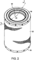
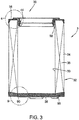
- an air filter element 30 which, as also shown in FIGS. 2 and 3 , is made up of a so-called filter media pack 32 which is made up of an inner liner 33 and an outer liner 34 sandwiching a tube of filter media 35.
- the lower end of the filter 30 is sealed by way of a closed end cap 36 which, as will be described below, is a potted element which encapsulates the filter media 35 and the liners 33, 34.
- the other end of the filter element 30 includes an open end cap in the form of an annular ring 38 which, like the end cap 36, encapsulates the ends of the filter media 35 and the liners 33, 34.
- the upper end cap 38 has an aperture for receiving an air inlet element, in the present example the tube 26.
- the end cap 38 is formed with a resilient radial seal 40 which is supported on a ring carried by the end cap 38, but is relatively isolated from the inner liner 33.
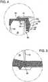
- the structure of the radial seal 40 and the open end cap 38 is best appreciated with concurrent reference to FIGS. 3 and 4 .
- the open end cap 38 is formed of a resilient rubbery material, in the preferred embodiment a foamed polyurethane which expands during cure. Embedded within the rubbery material is the base 41 of a substantially stiff insert ring 42.
- the insert ring 42 has a cylindrical flange 43 projecting from the end cap 38.
- a formed-in-place gasket 44, of the same material as the end cap 38, and formed concurrently with the end cap 38 is carried on a first surface 45 of the flange 43.
- a second or rearward facing surface 46 of the cylindrical flange 43 is substantially free of the urethane material which forms the end cap 38, so that a gap 50, substantially free of urethane material, is present between the surface 46 of the cylindrical flange and the inner liner 33.
- the comparative stiffness of the closed ring 42 and the gap 50 between the ring and the liner serve to isolate the gasket 44 from the inner liner 33 for reasons which will be explained below.
- the gasket 44 maintains its seal under temperature extremes and in the presence of vibration, even when the loading on the inner liner 33 would attempt to impose uneven pressures.
- the ring 42, and particularly its flange 43 is described herein as being substantially stiff. By that is meant materials, typically plastic, which are rigid or semi-rigid and when formed in a ring shape as illustrated will tend to maintain shape and dimensional stability under conditions normally encountered in such filter applications.
- the ring 42 has a base section generally indicated at 41 and a flange section generally indicated at 43. As will be appreciated from FIG. 3 , the base 41 is encapsulated in the end cap material 38 and the flange 43 projects from the end cap.
- the ring 42 includes a plurality of feet 51 which are distributed about the periphery of the ring for supporting the ring in a mold during formation of the end cap.
- the flange section 43 supported by the base 41, includes a tapered portion 53 followed by a sealing portion 54.
- the portion 54 has an outer diameter which snugly fits within the inside of the inner liner, and thus serves as a fluid restriction.
- the tapered portion 53 guides the inner liner onto the sealing portion 54.
- the fit between the portion 54 and the inner liner can be considered a zero clearance fit, intended to restrict the foamed polyurethane from penetrating the fit to enter into the open area 50 ( FIG. 4 ) between the unmolded surface of the flange and the inner liner.
- the foamed urethane will follow the path of least resistance as it expands, and the fluid restriction is intended to take advantage of that fact by allowing the urethane a lower resistance path into the pleats of the filter media.
- a tapered section 56 overlies the vertical portion 55 of the cylindrical flange 43.
- the tapered portion 56 serves to cap the rise of the urethane material.
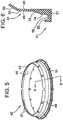
- the ring also include a plurality of apertures 57 (see FIG. 5 ) through which the urethane material penetrates to form mechanical locks between the plastic insert ring 42 and the formed end cap 38.
- each of the feet 51 includes a base surface 60 adapted to engage the bottom of the inner liner and serve as a stop for the inner liner.
- a continuous ring 62 is also carried on the feet 51. The ring 62 serves to engage the lower portion of the filter media 35 to fix the filter media in place during the molding operation.
- the outer liner is to be held in place by the mold as will be described below.
- a body 70 provides gasket forming surfaces 72 for defining the shape of the outer surface of the radial seal gasket.
- the preferred gasket has a tapered lead-in section 72a joining a substantially straight sided cylindrical sealing portion 72b. (See FIG. 4 )
- the portions 72 of the mold are important in providing this feature.
- the base of the mold has a circular rim 73 on which the feet 51 of the ring are to be supported.
- a lower surface 74, positioned somewhat below the rim 73 is adapted to define the bottom of the gasket.
- a feature 75 for forming a locating rim is provided in the mold contour.
- An upper platform 76 is provided for supporting the outer liner and also serves as a seat for the outer portion of the filter element. Gripping notches are formed in the outer portion of the molded end cap by means of the localized formed notches 78.
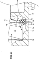
- FIG. 8 shows the mold (left hand side only) placed in operative association with a filter media pack 32 during the molding operation. Just prior to placing of the filter elements, a measured quantity of urethane and activator material are deposited in the lower portion of the mold. The material is distributed by way of the shape of the mold such that a significant quantity of material is available to foam into and fill the area where the seal is to be formed.
- a chamber 80 is created which is the area in which the radial seal gasket will be formed.
- the transition and sealing surfaces 72a, 72b for the radial seal gasket are formed by the surfaces 72 of the mold.
- the second side of the chamber is bounded by the face 45 of the insert ring 42.
- the feet 51 of the ring 42 sit on the base 73.
- the inner liner has been guided by tapered section 53 of the insert ring into contact with the sealing section 54 while being supported at the portion 60 of the feet 51.
- the tubular filter element is supported on the ring 62 near it inner periphery, and on the floor 76 at its outer periphery.
- the outer liner is also supported on the floor 76. A sufficient space between the outer liner and the end wall of the mold provides for a rubber seal which encapsulates the outer liner.
- the material With the urethane and activator materials having been placed, the material will immediately begin to expand to fill the gap 80 and form the radial seal gasket. At the same time, the material will rise to a lesser extent to encompass and encapsulate the lower portions of the inner and outer liners and the lower portion of the filter media.
- the floor of the molded material and the outer periphery of the molded material are determined by the shape of the mold, while the upper extent, the penetration into the filter, is controlled by the quantity of material which is placed.
- the fluid restriction between the inner liner and the surface 54 of the sealing ring tend to restrain the foaming urethane from entering the gap 50 ( FIG. 4 ) which is formed between the cylindrical flange and the inner liner.
- the filter After curing of the urethane material, which is relatively quick, the filter is removed from the mold portion 70.
- the gasket portion 72 has sufficient resilience to allow removal of the molded end cap from the mold 70.
- the filter can then be inverted and the second closed end cap encapsulated to completely seal the second end.
- the mold portions for the closed end cap are not illustrated in the drawings. All that is required is a relatively simple lower mold cup, since upper expansion need not be controlled by a mold, but can be controlled solely by placement and quantity of materials.
- One feature of significance in the lower mold is the provision of a rim 95 (a depression in the mold) which is substantially congruent with the position of the inner liner. Forming the mold in that fashion forms the end cap as best illustrated in FIG. 9 with an enlarged circular ridge 90 which represents an increase in material quantity and thickness at the position where the inner line is encapsulated into the closed end cap. This extra material tends to reduce stress concentrations which would otherwise be imposed on the relatively thin end cap material. It helps to prevent failure of the end cap or movement of the inner liner within the end cap.
- the closed end cap can also be formed to produce mounting feet 95 (see FIG. 1 ) as is conventional.
- a substantially stiff insert ring has a base encapsulated in the foam material which forms the end cap and an upstanding cylindrical flange which carries the radial seal gasket on one surface and is protected from deposit of substantial urethane material on the other surface.
Landscapes
- Chemical & Material Sciences (AREA)
- Engineering & Computer Science (AREA)
- Chemical Kinetics & Catalysis (AREA)
- Combustion & Propulsion (AREA)
- Mechanical Engineering (AREA)
- General Engineering & Computer Science (AREA)
- Physics & Mathematics (AREA)
- Geometry (AREA)
- Filtering Of Dispersed Particles In Gases (AREA)
Claims (11)
- Élément de filtrage d'air (30) comprenant en combinaison :un milieu filtrant tubulaire (35) comportant des première etdeuxième extrémités ;des revêtements tubulaires intérieur (33) et extérieur (34) supportant le milieu filtrant (35) et comportant également des première et deuxième extrémités ; caractérisé par l'élément de filtre (30) comportant un capuchon d'extrémité fermé (36) formé de matériau de mousse moulé encapsulant les premières extrémités des revêtements (33, 34) et du milieu filtrant (35) ;un anneau d'insert (42) de matériau plastique sensiblement rigide comportant :une bride cylindrique (43) présentant une surface intérieure (45) positionnée pour supporter un joint (44) ;une partie d'étanchéité (54) supportant la bride cylindrique (43) et dimensionnée pour s'ajuster parfaitement dans le revêtement intérieur (33), la partie d'étanchéité (54) et le revêtement intérieur formant un ajustement avec jeu nul en tant que restriction de fluide, et la restriction de fluide empêchant le matériau de mousse de pénétrer dans l'ajustement et d'entrer dans la zone ouverte (50) entre la surface non moulée de la bride cylindrique (43) et le revêtement intérieur (33) ;une partie de base (41) supportant la partie d'étanchéité (54) ;l'anneau d'insert (42) étant ajusté dans la deuxième extrémité du revêtement intérieur (33) avec la partie d'étanchéité (54) engageant parfaitement le revêtement intérieur (33) ; etun capuchon d'extrémité ouvert (38) formé de matériau de mousse compressible moulé d'élasticité suffisante pour servir de joint, le matériau de mousse englobant la partie de base (41) de l'anneau d'insert (42), les deuxièmes extrémités des revêtements (33, 34) et du milieu filtrant (35) et la surface intérieure (45) de la bride cylindrique (43), la forme et la dimension dudit matériau de mousse sur la surface intérieure (45) étant configurées pour former un joint d'étanchéité en tant que partie du capuchon d'extrémité ouvert (38).
- Combinaison selon la revendication 1 dans laquelle l'anneau d'insert (42) présente une partie effilée (53) entre la bride cylindrique (43) et la partie d'étanchéité (54), la partie effilée (53) étant dimensionnée pour engager le revêtement intérieur (33) pour guider le revêtement intérieur (33) vers la partie d'étanchéité (54).
- Combinaison selon la revendication 2 dans laquelle la partie d'étanchéité (54) comprend une partie cylindrique sensiblement à côtés droits positionnée entre la partie effilée (53) et la partie de base (41).
- Combinaison selon la revendication 1 incluant en outre un support de revêtement positionné sous la partie d'étanchéité (54) et supporté par la partie de base (41).
- Combinaison selon la revendication 4 dans laquelle la partie de base (41) comprend une pluralité de pieds (51) supportant la partie d'étanchéité (54) et définissant le support de revêtement.
- Combinaison selon la revendication 5 incluant en outre un support de milieu filtrant en forme d'anneau (62) positionné sur la pluralité de pieds (51) dans une position pour supporter le milieu filtrant (53).
- Combinaison selon la revendication 6 dans laquelle la bride cylindrique (43) de l'anneau d'insert (42) inclut une section effilée supérieure (56) positionnée pour limiter le déplacement du matériau de mousse compressible durant le moulage.
- Combinaison selon la revendication 7 dans laquelle l'angle de l'effilage est suffisant pour augmenter la rigidité de l'anneau d'insert (42).
- Combinaison selon la revendication 7 dans laquelle la section effilée supérieure (56) inclut une pluralité d'ouvertures (57) remplies du matériau de mousse pour fournir un verrouillage mécanique entre l'anneau d'insert (42) et le matériau de mousse pour amener le matériau à remplir lesdites ouvertures (57) et empêcher la rotation de l'anneau (42) dans le filtre (30).
- Combinaison selon la revendication 1 dans laquelle la forme du matériau de mousse sur la surface intérieure (45) de la bride cylindrique inclut une partie d'entrée effilée (72a) joignant une partie cylindrique (72b) sensiblement à côtés droits dudit joint (44).
- Combinaison selon la revendication 1 dans laquelle le capuchon d'extrémité fermé (36) inclut une arête surélevée (90) concentrique avec l'élément de filtre (30) et positionnée sur le revêtement intérieur (33) pour réduire la concentration de contraintes causée par la flexion du revêtement intérieur (33).
Applications Claiming Priority (3)
| Application Number | Priority Date | Filing Date | Title |
|---|---|---|---|
| US09/854,650 US6447567B1 (en) | 2001-05-14 | 2001-05-14 | Air filter element with integral radial seal gasket |
| EP01203469.0A EP1258278B2 (fr) | 2001-05-14 | 2001-09-14 | Filtre à air avec joint d'étanchéité radial intégré |
| EP07023233.5A EP1889648B1 (fr) | 2001-05-14 | 2001-09-14 | Élément de filtre à air doté d'un joint d'étanchéité radial intégral |
Related Parent Applications (3)
| Application Number | Title | Priority Date | Filing Date |
|---|---|---|---|
| EP07023233.5A Division EP1889648B1 (fr) | 2001-05-14 | 2001-09-14 | Élément de filtre à air doté d'un joint d'étanchéité radial intégral |
| EP01203469.0A Division EP1258278B2 (fr) | 2001-05-14 | 2001-09-14 | Filtre à air avec joint d'étanchéité radial intégré |
| EP01203469.0A Division-Into EP1258278B2 (fr) | 2001-05-14 | 2001-09-14 | Filtre à air avec joint d'étanchéité radial intégré |
Publications (3)
| Publication Number | Publication Date |
|---|---|
| EP3097968A2 EP3097968A2 (fr) | 2016-11-30 |
| EP3097968A3 EP3097968A3 (fr) | 2016-12-28 |
| EP3097968B1 true EP3097968B1 (fr) | 2020-11-25 |
Family
ID=25319244
Family Applications (3)
| Application Number | Title | Priority Date | Filing Date |
|---|---|---|---|
| EP07023233.5A Expired - Lifetime EP1889648B1 (fr) | 2001-05-14 | 2001-09-14 | Élément de filtre à air doté d'un joint d'étanchéité radial intégral |
| EP01203469.0A Expired - Lifetime EP1258278B2 (fr) | 2001-05-14 | 2001-09-14 | Filtre à air avec joint d'étanchéité radial intégré |
| EP16159181.3A Expired - Lifetime EP3097968B1 (fr) | 2001-05-14 | 2001-09-14 | Élément de filtre à air doté d'un joint d'étanchéité radial intégral |
Family Applications Before (2)
| Application Number | Title | Priority Date | Filing Date |
|---|---|---|---|
| EP07023233.5A Expired - Lifetime EP1889648B1 (fr) | 2001-05-14 | 2001-09-14 | Élément de filtre à air doté d'un joint d'étanchéité radial intégral |
| EP01203469.0A Expired - Lifetime EP1258278B2 (fr) | 2001-05-14 | 2001-09-14 | Filtre à air avec joint d'étanchéité radial intégré |
Country Status (8)
| Country | Link |
|---|---|
| US (1) | US6447567B1 (fr) |
| EP (3) | EP1889648B1 (fr) |
| KR (1) | KR100490696B1 (fr) |
| AU (1) | AU753090B1 (fr) |
| CA (1) | CA2357071C (fr) |
| DE (1) | DE60132559T3 (fr) |
| ES (1) | ES2301517T3 (fr) |
| ZA (1) | ZA200107584B (fr) |
Families Citing this family (94)
| Publication number | Priority date | Publication date | Assignee | Title |
|---|---|---|---|---|
| DE10049313A1 (de) * | 2000-10-05 | 2002-04-11 | Audi Ag | Gehäuse zur Aufnahme eines Luftfilterelements |
| US6537355B2 (en) * | 2000-12-27 | 2003-03-25 | Delphi Technologies, Inc. | Evaporative emission treatment device |
| US7734715B2 (en) * | 2001-03-01 | 2010-06-08 | Ricoh Company, Ltd. | System, computer program product and method for managing documents |
| US6712870B1 (en) * | 2001-11-30 | 2004-03-30 | Dana Corporation | Seals for air filters |
| US6966940B2 (en) | 2002-04-04 | 2005-11-22 | Donaldson Company, Inc. | Air filter cartridge |
| US20040025485A1 (en) * | 2002-08-07 | 2004-02-12 | Dong-Tasi Lee | Air filter with molded end caps |
| US20040103626A1 (en) * | 2002-08-23 | 2004-06-03 | Warth Scott B. | Filter element, filter assembly, gas turbine system, and methods |
| WO2004039476A1 (fr) | 2002-10-28 | 2004-05-13 | Donaldson Company, Inc. | Filtre a air, cartouches de filtres remplaçables et procedes |
| US7537631B2 (en) | 2002-10-28 | 2009-05-26 | Donaldson Company, Inc. | Filter cartridges; air cleaners; and methods |
| US7650999B2 (en) * | 2002-12-16 | 2010-01-26 | Wix Filtration Corp Llc | End cap and gasket assemblies for filter elements |
| KR20050098922A (ko) | 2003-02-11 | 2005-10-12 | 도널드선 컴파니 인코포레이티드 | 에어 크리너 배열과 서비스가능한 필터 구성 요소 및 방법 |
| US6902598B2 (en) | 2003-05-02 | 2005-06-07 | Fleetguard, Inc. | Filter with efficiently sealed end |
| DE502004011118D1 (de) * | 2003-07-18 | 2010-06-17 | Mann & Hummel Gmbh | Filterelement, insbesondere zur Reinigung von Verbrennungsluft |
| WO2007056589A2 (fr) | 2005-11-09 | 2007-05-18 | Donaldson Company, Inc. | Dispositif d’etancheite destine a un element filtrant, ensemble element filtrant et procedes |
| US20090266041A1 (en) * | 2003-12-22 | 2009-10-29 | Donaldson Company, Inc. | Seal arrangement for filter element; Filter element assembly; and, methods |
| US7396376B2 (en) | 2003-12-22 | 2008-07-08 | Donaldson Company, Inc. | Seal arrangement for filter element; filter element assembly; and, methods |
| EP1729621B1 (fr) | 2004-03-24 | 2013-03-20 | Donaldson Company, Inc. | Cartouche de filtration d'air et procede de fabrication |
| US20050229563A1 (en) * | 2004-04-19 | 2005-10-20 | Holzmann Mark V | Filter element |
| GB0409548D0 (en) * | 2004-04-29 | 2004-06-02 | King S College London | Robotic hand |
| EP1748831B1 (fr) | 2004-04-30 | 2012-06-13 | Donaldson Company, Inc. | Dispositifs de filtration et méthode |
| EP2243536B1 (fr) | 2004-06-14 | 2013-11-20 | Donaldson Company, Inc. | Ensemble filtre a air et cartouche de filtre |
| DE102004033550A1 (de) * | 2004-07-09 | 2006-02-16 | Klebchemie, M.G. Becker Gmbh & Co Kg | Polymerdichtung |
| WO2006017790A1 (fr) | 2004-08-06 | 2006-02-16 | Donaldson Company, Inc. | Agencement de filtre à air; montage; et, procédés |
| US8216335B2 (en) | 2004-08-25 | 2012-07-10 | Donaldson Company, Inc. | Air cleaner; replaceable filter cartridges; and methods |
| US8042694B2 (en) * | 2004-11-02 | 2011-10-25 | Baldwin Filters, Inc. | Gathered filter media for an air filter and method of making same |
| US20110197556A1 (en) | 2004-11-02 | 2011-08-18 | Baldwin Filters, Inc. | Filter element |
| US7318851B2 (en) | 2004-11-02 | 2008-01-15 | Baldwin Filters, Inc. | Filter element |
| US20060090431A1 (en) * | 2004-11-02 | 2006-05-04 | Baldwin Filters, Inc. | Filter assembly with combination filter element |
| US20060091084A1 (en) * | 2004-11-02 | 2006-05-04 | Baldwin Filters, Inc. | Fluted filter media with intermediate flow restriction and method of making same |
| US7931725B2 (en) | 2004-11-02 | 2011-04-26 | Baldwin Filters, Inc. | Fluted filter apparatus |
| US7255300B2 (en) | 2004-11-03 | 2007-08-14 | Baldwin Filters, Inc. | Method and apparatus for winding a filter media pack |
| US7909954B2 (en) | 2004-11-03 | 2011-03-22 | Baldwin Filters, Inc. | Method and apparatus for winding a filter media pack |
| US7569090B2 (en) | 2004-11-12 | 2009-08-04 | Donaldson Company, Inc. | Method of forming filter arrangements; and, apparatus |
| US7828870B1 (en) | 2004-11-24 | 2010-11-09 | Cummins Filtration Ip, Inc. | Filter assembly with cost effective seal |
| US7413588B2 (en) * | 2004-11-24 | 2008-08-19 | Fleetguard, Inc. | High efficiency, low restriction, cost effective filter |
| US7520913B2 (en) | 2005-02-04 | 2009-04-21 | Donaldson Company, Inc. | Non-cylindrical filter elements, and methods |
| US7524349B2 (en) * | 2005-05-03 | 2009-04-28 | Donaldson Company, Inc. | Air cleaner; air filter cartridge and method of manufacturing |
| WO2007044677A1 (fr) | 2005-10-11 | 2007-04-19 | Donaldson Company, Inc. | Agencement de filtre a air, ensemble et procedes |
| US7628837B2 (en) * | 2005-10-19 | 2009-12-08 | Baldwin Filters, Inc. | Air filter with composite end cap |
| US7815705B2 (en) * | 2005-10-19 | 2010-10-19 | Baldwin Filters, Inc. | Air filter with composite end cap |
| US20070163945A1 (en) * | 2006-01-19 | 2007-07-19 | Baldwin Filters, Inc. | Method and apparatus for reinforcing a tubular-shaped sealing collar extending from a filter apparatus |
| EP1986761A2 (fr) | 2006-01-20 | 2008-11-05 | Donaldson Company, Inc. | Epurateur d'air conçu pour recevoir des cartouches filtrantes de diverses tailles, composants de celui-ci et procedes associes |
| US7753982B2 (en) * | 2006-02-17 | 2010-07-13 | Baldwin Filters, Inc. | Filter with drained jacket, seal indicator/lock means, and seal baffle |
| US7740679B2 (en) * | 2006-04-18 | 2010-06-22 | Baldwin Filters, Inc. | Air filter element with composite molded end cap |
| WO2007149561A2 (fr) | 2006-06-22 | 2007-12-27 | Donaldson Company, Inc. | Arrangements de nettoyeur d'air, composants de celui-ci et méthodes |
| US7713321B2 (en) | 2006-06-22 | 2010-05-11 | Donaldson Company, Inc. | Air cleaner arrangements; components thereof; and, methods |
| US8273143B2 (en) | 2006-10-06 | 2012-09-25 | Donaldson Company, Inc. | Air cleaner, replaceable filter cartridges, and methods |
| US10040020B2 (en) | 2006-12-06 | 2018-08-07 | Baldwin Filters, Inc. | Fluid filter apparatus having filter media wound about a winding frame |
| US9757676B2 (en) | 2006-12-06 | 2017-09-12 | Baldwin Filters, Inc. | Method and apparatus for winding a filter element |
| US8673196B2 (en) * | 2007-02-28 | 2014-03-18 | Fram Group Ip Llc | Radial seal filter with open end pleats |
| WO2008124437A2 (fr) | 2007-04-03 | 2008-10-16 | Donaldson Company, Inc. | Épurateur d'air ; cartouche de filtre à air et procédé de fabrication |
| US8066791B2 (en) | 2007-07-20 | 2011-11-29 | Donaldson Company, Inc. | Air cleaner arrangements with internal and external support for cartridge; components; and, methods |
| US8292984B2 (en) | 2007-07-20 | 2012-10-23 | Donaldson Company, Inc. | Air cleaner arrangments with end support for cartridge; components; and, methods |
| GB0716659D0 (en) * | 2007-08-25 | 2007-10-03 | Madison Filter 981 Ltd | Filter element constructions |
| US8728193B2 (en) | 2007-09-07 | 2014-05-20 | Donaldson Company, Inc. | Air filter assembly; components thereof and methods |
| DE202007013822U1 (de) * | 2007-10-02 | 2009-02-19 | Mann+Hummel Gmbh | Filterelement und Filtersystem |
| DE202007014821U1 (de) * | 2007-10-02 | 2009-02-26 | Mann+Hummel Gmbh | Filterelement V-Dichtung |
| DE202007014822U1 (de) * | 2007-10-02 | 2009-02-19 | Mann+Hummel Gmbh | Filterelement Zackendichtung |
| US9545593B2 (en) | 2007-11-01 | 2017-01-17 | Baldwin Filters, Inc. | Winding core pressure relief for fluted filter |
| US7959703B2 (en) | 2008-06-30 | 2011-06-14 | Baldwin Filters, Inc. | Fluted filter with integrated frame |
| US8048187B2 (en) | 2008-06-30 | 2011-11-01 | Baldwin Filters, Inc. | Filter frame attachment and fluted filter having same |
| US8080159B2 (en) * | 2008-08-19 | 2011-12-20 | Cummins Filtration Ip, Inc. | Centertube for a combination full flow and bypass filter apparatus |
| KR200460765Y1 (ko) * | 2009-11-12 | 2012-06-14 | 주식회사 세원 | 차량용 공기 여과기 |
| EP2678091A1 (fr) | 2011-02-25 | 2014-01-01 | Donaldson Company, Inc. | Cartouches de filtre à air et ses composants, et ensembles épurateurs d'air |
| US20130206669A1 (en) * | 2011-08-02 | 2013-08-15 | Wix Filtration Corp Llc | Filter Endcap With Integral Seal, Filter Assembly and Methods for Manufacturing the Same |
| US20130032521A1 (en) * | 2011-08-02 | 2013-02-07 | Wix Filtration Corp Llc | Filter Endcap With Integral Seal, Filter Assembly and Methods for Manufacturing the Same |
| US8673037B2 (en) | 2011-10-18 | 2014-03-18 | Camfil Farr, Inc. | Air filter with balanced seal |
| CN106861310B (zh) | 2011-10-26 | 2020-04-10 | 唐纳森公司 | 过滤器组件、其部件和特征、以及使用和组装的方法 |
| CN107081026B (zh) | 2011-10-31 | 2019-07-23 | 唐纳森公司 | 空气过滤器组件 |
| CN202721947U (zh) * | 2011-11-03 | 2013-02-06 | 卢子鬯 | 电子仪器用之无卤素阻燃电磁干扰防护垫片 |
| WO2013096646A1 (fr) | 2011-12-20 | 2013-06-27 | Eclipse, Inc. | Procédé et appareil pour brûleur à deux modes produisant une faible émission de nox |
| US20130305672A1 (en) * | 2012-05-16 | 2013-11-21 | Purolator Filters Na Llc | Helical/Spiral Seal Air Filter |
| WO2014018528A1 (fr) | 2012-07-25 | 2014-01-30 | Baldwin Filters, Inc. | Boîtier de filtre, filtre plissé et filtre de sécurité |
| US9089804B2 (en) | 2012-11-19 | 2015-07-28 | Donaldson Company, Inc. | Filter arrangements; components; assemblies; and, methods |
| EP2742986B1 (fr) * | 2012-12-17 | 2018-04-18 | Mann + Hummel Gmbh | Système de filtre à air, élément de filtre à air et procédé de remplacement d'un élément de filtre à air |
| US10315147B2 (en) | 2014-09-15 | 2019-06-11 | Donaldson Company, Inc. | Filter cartridges; air cleaner assemblies; housings; features; components; and, methods |
| US12467537B2 (en) * | 2015-06-01 | 2025-11-11 | Mann+Hummel Gmbh | Sealing element, annular filter element, oil separator, and method for controlling prevailing pressure in crankcase ventilation system |
| EP3101244B1 (fr) * | 2015-06-01 | 2021-04-07 | Mann + Hummel Gmbh | Élement d'etancheite, element de filtre annulaire, separateur d'huile et procede d'ouverture d'un carter de filtre d'un separateur d'huile |
| US10112133B2 (en) | 2015-07-20 | 2018-10-30 | Caterpillar Inc. | Filter housing with end cap seal |
| RU2741961C2 (ru) | 2016-02-12 | 2021-02-01 | Дональдсон Компани, Инк. | Фильтрующие элементы, воздухоочистительные узлы и способы применения и сборки |
| BR112018016914B1 (pt) | 2016-02-19 | 2023-04-25 | Baldwin Filters, Inc | Elemento de filtro e método de aplicar um revestimento líquido a um filtro |
| EP3433004B1 (fr) * | 2016-03-24 | 2022-04-27 | K & N Engineering, Inc. | Système de filtre à air réutilisable et procédé correspondant |
| US10682597B2 (en) | 2016-04-14 | 2020-06-16 | Baldwin Filters, Inc. | Filter system |
| CN110248716B (zh) | 2016-12-01 | 2021-09-28 | 唐纳森公司 | 滤芯、空气滤清器组件、以及使用和组装方法 |
| EP3401000A1 (fr) | 2017-05-09 | 2018-11-14 | Donaldson Company, Inc. | Adaptateur et cartouche de filtre à air conçue pour être utilisée avec un tel adaptateur |
| US10760536B2 (en) | 2017-10-27 | 2020-09-01 | Indian Motorcycle International, LLC | Air box for a vehicle |
| WO2020112536A1 (fr) * | 2018-11-28 | 2020-06-04 | Cummins Filtration Ip, Inc. | Joint incurvé sur élément filtrant et moule de joint de protection |
| EP3906108B9 (fr) * | 2018-12-31 | 2023-10-25 | Cummins Filtration IP, Inc. | Élément d'étanchéité d'embout d'extrémité multifonctionnel intégré |
| WO2020231769A1 (fr) | 2019-05-14 | 2020-11-19 | Cummins Filtration Ip, Inc. | Système de filtre à air à verrouillage étanche à lobes incurvé |
| IL269021B2 (en) * | 2019-08-29 | 2023-05-01 | Riskin Yefim | Air disinfection method and disinfection device |
| TWI699233B (zh) * | 2019-09-12 | 2020-07-21 | 濾能股份有限公司 | 筒狀過濾裝置、其製造方法與用途、以及包含筒狀過濾裝置之過濾系統 |
| CN113440948B (zh) * | 2020-03-25 | 2022-10-21 | Oppo(重庆)智能科技有限公司 | 清洁设备 |
| US11772028B2 (en) | 2020-06-01 | 2023-10-03 | The Sy-Klone Company, Llc | Radial seal filter |
| CN112429400A (zh) * | 2020-11-09 | 2021-03-02 | 湖南冠一颜料有限公司 | 一种三氧化二铁颜料生产用的氧化桶密封装置 |
Family Cites Families (23)
| Publication number | Priority date | Publication date | Assignee | Title |
|---|---|---|---|---|
| US4349363A (en) * | 1980-10-27 | 1982-09-14 | Incom International Inc. | Filter element ledge gasket |
| US4350509A (en) | 1981-07-24 | 1982-09-21 | Donaldson Company, Inc. | Disposable air cleaner |
| GB8319167D0 (en) * | 1983-07-15 | 1983-08-17 | Marshall D A G | Fluid filter element |
| US4720292B1 (en) | 1986-07-14 | 1991-09-10 | Cylindrical air filter with lightweight housing and radially directed seal | |
| DE3934433A1 (de) * | 1989-10-14 | 1991-04-25 | Mann & Hummel Filter | Luftfilter mit radial abdichtendem filtereinsatz |
| DE9011419U1 (de) * | 1990-08-06 | 1990-10-11 | Filterwerk Mann & Hummel Gmbh, 7140 Ludwigsburg | Ansaugluftfilter für die Verbrennungskraftmaschine eines Fahrzeugs |
| DE4241586C1 (de) * | 1992-12-10 | 1994-01-27 | Mann & Hummel Filter | Luftfilter |
| US5487767A (en) * | 1993-09-30 | 1996-01-30 | Dana Corporation | Radially sealed air filters |
| US5415677A (en) * | 1993-12-28 | 1995-05-16 | Dana Corporation | Air filters including filters configured for both radial and axial sealing |
| US5547480A (en) * | 1994-01-21 | 1996-08-20 | Donaldson Company, Inc. | Cylindrical air filter with radially directed seal |
| US5484466A (en) | 1994-02-14 | 1996-01-16 | Baldwin Filters, Inc. | Air filter element with radial seal sealing gasket |
| SE506017C2 (sv) * | 1994-05-10 | 1997-11-03 | Volvo Ab | Luftfilter |
| JP3468436B2 (ja) * | 1994-09-22 | 2003-11-17 | 豊田紡織株式会社 | 樹脂製エアクリーナ |
| EP0802820B1 (fr) * | 1995-01-12 | 2001-04-04 | Donaldson Company, Inc. | Element filtrant |
| US5803941A (en) * | 1995-01-12 | 1998-09-08 | Donaldson Company, Inc. | Filter element |
| US5669949A (en) * | 1995-04-21 | 1997-09-23 | Donaldson Company, Inc. | Air filtration arrangement |
| US5685985A (en) * | 1995-12-20 | 1997-11-11 | Baldwin Filters, Inc. | Environmentally friendly filter cartridge |
| DE19613847A1 (de) * | 1996-04-06 | 1997-10-09 | Hydac Filtertechnik Gmbh | Filtervorrichtung |
| DE19634720A1 (de) * | 1996-08-28 | 1998-03-05 | Mann & Hummel Filter | Filterpatrone |
| AU2970899A (en) * | 1998-02-19 | 1999-09-06 | Donaldson Company Inc. | Air filtration arrangements and methods |
| US6099606A (en) * | 1998-03-19 | 2000-08-08 | Donaldson Company, Inc. | Air filtration arrangements having spacer constructions |
| US6261334B1 (en) * | 1999-01-29 | 2001-07-17 | Nelson Industries, Inc. | High flow capacity filter |
| US6383244B1 (en) * | 2000-10-20 | 2002-05-07 | Nelson Industries, Inc. | Filter with retained safety element |
-
2001
- 2001-05-14 US US09/854,650 patent/US6447567B1/en not_active Expired - Lifetime
- 2001-09-11 AU AU69982/01A patent/AU753090B1/en not_active Ceased
- 2001-09-13 CA CA002357071A patent/CA2357071C/fr not_active Expired - Lifetime
- 2001-09-14 ES ES01203469T patent/ES2301517T3/es not_active Expired - Lifetime
- 2001-09-14 EP EP07023233.5A patent/EP1889648B1/fr not_active Expired - Lifetime
- 2001-09-14 EP EP01203469.0A patent/EP1258278B2/fr not_active Expired - Lifetime
- 2001-09-14 DE DE60132559.1T patent/DE60132559T3/de not_active Expired - Lifetime
- 2001-09-14 ZA ZA200107584A patent/ZA200107584B/xx unknown
- 2001-09-14 EP EP16159181.3A patent/EP3097968B1/fr not_active Expired - Lifetime
- 2001-09-17 KR KR10-2001-0057143A patent/KR100490696B1/ko not_active Expired - Fee Related
Non-Patent Citations (1)
| Title |
|---|
| None * |
Also Published As
| Publication number | Publication date |
|---|---|
| DE60132559T2 (de) | 2009-01-29 |
| US6447567B1 (en) | 2002-09-10 |
| DE60132559T3 (de) | 2019-04-25 |
| EP1258278B1 (fr) | 2008-01-23 |
| EP1889648A2 (fr) | 2008-02-20 |
| ES2301517T3 (es) | 2008-07-01 |
| ZA200107584B (en) | 2002-05-14 |
| EP3097968A3 (fr) | 2016-12-28 |
| EP1258278B2 (fr) | 2018-12-05 |
| HK1112435A1 (en) | 2008-09-05 |
| CA2357071C (fr) | 2003-02-11 |
| KR100490696B1 (ko) | 2005-05-24 |
| KR20020088047A (ko) | 2002-11-25 |
| EP1258278A2 (fr) | 2002-11-20 |
| AU753090B1 (en) | 2002-10-10 |
| EP1258278A3 (fr) | 2003-11-19 |
| DE60132559D1 (de) | 2008-03-13 |
| EP3097968A2 (fr) | 2016-11-30 |
| EP1889648B1 (fr) | 2016-03-16 |
| EP1889648A3 (fr) | 2008-03-05 |
| CA2357071A1 (fr) | 2001-11-24 |
Similar Documents
| Publication | Publication Date | Title |
|---|---|---|
| EP3097968B1 (fr) | Élément de filtre à air doté d'un joint d'étanchéité radial intégral | |
| US5484466A (en) | Air filter element with radial seal sealing gasket | |
| KR102201240B1 (ko) | 필터 배열; 구성요소; 어셈블리; 및 방법 | |
| US8016922B2 (en) | Air filter with composite end cap | |
| US6058963A (en) | Vehicle refueling valve | |
| US4673419A (en) | Air dryer device | |
| US20040068970A1 (en) | Air filter element and method of producing the same | |
| CA2622232C (fr) | Filtre a air muni dun couvercle terminal composite | |
| US4989629A (en) | Fuel cut valve for vent line | |
| EP0999914B1 (fr) | Clapet a basculement pour bombe aerosol et procede de fabrication correspondant | |
| GB2054755A (en) | Electrical fuel pump unit | |
| US6435365B2 (en) | Seal assembly for a fuel tank | |
| US20010025652A1 (en) | Fuel cutoff valve and production method thereof | |
| JP2004522895A (ja) | 燃料タンク蒸気ベント弁組立体およびその製造方法 | |
| JP3741798B2 (ja) | 液面検知用バルブ | |
| HK1112435B (en) | Air filter element with integral radial seal gasket | |
| JP2004534692A (ja) | タンク内のバルブ装着 | |
| JPH0530655U (ja) | 車輌の燃料流出防止弁 | |
| JP2538627Y2 (ja) | 燃料タンク内配置の燃料蒸気通気弁の取付構造 | |
| JPS5941325Y2 (ja) | 乾式エアクリ−ナにおける合成樹脂製クリ−ナケ−ス | |
| US2718277A (en) | Air cleaner construction | |
| JPH0728832U (ja) | リザーバタンク |
Legal Events
| Date | Code | Title | Description |
|---|---|---|---|
| PUAI | Public reference made under article 153(3) epc to a published international application that has entered the european phase |
Free format text: ORIGINAL CODE: 0009012 |
|
| PUAL | Search report despatched |
Free format text: ORIGINAL CODE: 0009013 |
|
| AC | Divisional application: reference to earlier application |
Ref document number: 1889648 Country of ref document: EP Kind code of ref document: P Ref document number: 1258278 Country of ref document: EP Kind code of ref document: P |
|
| AK | Designated contracting states |
Kind code of ref document: A2 Designated state(s): DE ES GB IT |
|
| AK | Designated contracting states |
Kind code of ref document: A3 Designated state(s): DE ES GB IT |
|
| RIC1 | Information provided on ipc code assigned before grant |
Ipc: B01D 46/24 20060101AFI20161123BHEP Ipc: F02M 35/024 20060101ALI20161123BHEP Ipc: B01D 46/52 20060101ALI20161123BHEP |
|
| STAA | Information on the status of an ep patent application or granted ep patent |
Free format text: STATUS: REQUEST FOR EXAMINATION WAS MADE |
|
| 17P | Request for examination filed |
Effective date: 20170627 |
|
| RBV | Designated contracting states (corrected) |
Designated state(s): DE ES GB IT |
|
| STAA | Information on the status of an ep patent application or granted ep patent |
Free format text: STATUS: EXAMINATION IS IN PROGRESS |
|
| 17Q | First examination report despatched |
Effective date: 20190704 |
|
| GRAP | Despatch of communication of intention to grant a patent |
Free format text: ORIGINAL CODE: EPIDOSNIGR1 |
|
| STAA | Information on the status of an ep patent application or granted ep patent |
Free format text: STATUS: GRANT OF PATENT IS INTENDED |
|
| INTG | Intention to grant announced |
Effective date: 20200615 |
|
| GRAS | Grant fee paid |
Free format text: ORIGINAL CODE: EPIDOSNIGR3 |
|
| GRAA | (expected) grant |
Free format text: ORIGINAL CODE: 0009210 |
|
| STAA | Information on the status of an ep patent application or granted ep patent |
Free format text: STATUS: THE PATENT HAS BEEN GRANTED |
|
| AC | Divisional application: reference to earlier application |
Ref document number: 1889648 Country of ref document: EP Kind code of ref document: P Ref document number: 1258278 Country of ref document: EP Kind code of ref document: P |
|
| AK | Designated contracting states |
Kind code of ref document: B1 Designated state(s): DE ES GB IT |
|
| REG | Reference to a national code |
Ref country code: GB Ref legal event code: FG4D |
|
| REG | Reference to a national code |
Ref country code: DE Ref legal event code: R096 Ref document number: 60151313 Country of ref document: DE |
|
| REG | Reference to a national code |
Ref country code: DE Ref legal event code: R097 Ref document number: 60151313 Country of ref document: DE |
|
| REG | Reference to a national code |
Ref country code: DE Ref legal event code: R071 Ref document number: 60151313 Country of ref document: DE |
|
| PLBE | No opposition filed within time limit |
Free format text: ORIGINAL CODE: 0009261 |
|
| STAA | Information on the status of an ep patent application or granted ep patent |
Free format text: STATUS: NO OPPOSITION FILED WITHIN TIME LIMIT |
|
| PG25 | Lapsed in a contracting state [announced via postgrant information from national office to epo] |
Ref country code: IT Free format text: LAPSE BECAUSE OF FAILURE TO SUBMIT A TRANSLATION OF THE DESCRIPTION OR TO PAY THE FEE WITHIN THE PRESCRIBED TIME-LIMIT Effective date: 20201125 |
|
| 26N | No opposition filed |
Effective date: 20210826 |
|
| PG25 | Lapsed in a contracting state [announced via postgrant information from national office to epo] |
Ref country code: ES Free format text: LAPSE BECAUSE OF FAILURE TO SUBMIT A TRANSLATION OF THE DESCRIPTION OR TO PAY THE FEE WITHIN THE PRESCRIBED TIME-LIMIT Effective date: 20201125 |
|
| REG | Reference to a national code |
Ref country code: GB Ref legal event code: PE20 Expiry date: 20210913 |
|
| PG25 | Lapsed in a contracting state [announced via postgrant information from national office to epo] |
Ref country code: GB Free format text: LAPSE BECAUSE OF EXPIRATION OF PROTECTION Effective date: 20210913 |