EP3098030A1 - Carcasse de machine-outil portative - Google Patents
Carcasse de machine-outil portative Download PDFInfo
- Publication number
- EP3098030A1 EP3098030A1 EP15169325.6A EP15169325A EP3098030A1 EP 3098030 A1 EP3098030 A1 EP 3098030A1 EP 15169325 A EP15169325 A EP 15169325A EP 3098030 A1 EP3098030 A1 EP 3098030A1
- Authority
- EP
- European Patent Office
- Prior art keywords
- housing part
- housing
- groove
- spring
- hand tool
- Prior art date
- Legal status (The legal status is an assumption and is not a legal conclusion. Google has not performed a legal analysis and makes no representation as to the accuracy of the status listed.)
- Withdrawn
Links
- 230000000295 complement effect Effects 0.000 claims abstract description 7
- 239000000203 mixture Substances 0.000 claims description 14
- 230000003014 reinforcing effect Effects 0.000 claims description 13
- 238000001746 injection moulding Methods 0.000 claims description 3
- 230000037431 insertion Effects 0.000 claims description 2
- 238000003780 insertion Methods 0.000 claims description 2
- 238000002788 crimping Methods 0.000 claims 1
- 239000000463 material Substances 0.000 description 3
- 238000009825 accumulation Methods 0.000 description 1
- 230000002411 adverse Effects 0.000 description 1
- 238000001816 cooling Methods 0.000 description 1
- 210000003746 feather Anatomy 0.000 description 1
- 230000002787 reinforcement Effects 0.000 description 1
- 238000009423 ventilation Methods 0.000 description 1
Images


Classifications
-
- B—PERFORMING OPERATIONS; TRANSPORTING
- B25—HAND TOOLS; PORTABLE POWER-DRIVEN TOOLS; MANIPULATORS
- B25F—COMBINATION OR MULTI-PURPOSE TOOLS NOT OTHERWISE PROVIDED FOR; DETAILS OR COMPONENTS OF PORTABLE POWER-DRIVEN TOOLS NOT PARTICULARLY RELATED TO THE OPERATIONS PERFORMED AND NOT OTHERWISE PROVIDED FOR
- B25F5/00—Details or components of portable power-driven tools not particularly related to the operations performed and not otherwise provided for
- B25F5/02—Construction of casings, bodies or handles
Definitions
- the present invention relates to a hand tool housing with a first housing part, at the edge of a first stepped rabbet is formed and with a second housing part, at the edge of a second stepped rabbet is formed.
- the first stepped rebate and the second stepped rebate are formed complementary to each other, so that the first housing part and the second housing part can be assembled in an assembly direction.
- Such hand tool machines are basically known from the prior art and are used in hand power tools such as combi hammers or hammer drills.
- a portable power tool housing of the type mentioned above in that at the edge of the first housing part a groove and at the edge of the second housing part, a spring is formed, which form a transversely to the direction of interlocking positive tongue and groove connection.
- the tongue and groove connection is positively connected perpendicular to the composition direction and / or in the longitudinal direction of extension of the edge.
- the invention includes the realization that hand tool housing are typically made of plastic, in particular by injection molding, which can cause distortion and shrinkage of the housing parts. As a result, the housing parts of the portable power tool housing may not be dimensionally stable.
- the invention also includes the recognition that, in prior art portable power tool housings, a first shifter and second shifter shifter connection typically needs to be stabilized by internal reinforcing struts and / or reinforcing webs.
- the disadvantage here is, on the one hand, that there is an accumulation of material in the area of the stepped rebate pairing, which leads to sink marks, for example, leaks on the outside of the handheld power tool housing.
- the reinforcing struts or reinforcing webs typical in the prior art have a low strength, since they are typically made very thin for reasons of material parsimony become.
- said reinforcing struts or reinforcing webs cause a disturbing geometry which adversely affects a ventilation flow of a cooling fan provided by generating unwanted air turbulence.
- a tongue and groove connection is provided which makes it possible to dispense with the reinforcing struts and reinforcing webs just described, i. saves material and at the same time is particularly stable.
- the groove is provided on the longer in the assembly direction portion of the first stepped rabbet.
- the spring may be provided on the shorter in the direction of assembly portion of the stepped rebate. It has proven to be advantageous if the groove and the spring are arranged on the respective edges of the housing parts, that they are not visible from outside the housing when the first housing part and the second housing part are assembled.
- the groove, together with the longer portion of the first stepped rebate, can form a first minor stepped rebate.
- the spring may form a second secondary stage fold together with a longer portion of the second stage rabbet in the assembly direction.
- the first Maustichnfalz and the second Maumenfalz are formed complementary to each other. Such results in a particularly advantageous cohesion of the first and second housing part in the assembled state.
- the groove and / or the spring has a height-to-width ratio between 1: 1 and 1: 3.
- a height-to-width ratio is preferably about 1: 2.
- a height is to be understood to mean an extension of the groove and / or the spring parallel to the composition direction.
- a width is to be understood to mean an extension of the groove and / or the spring transversely to the composition direction, in particular perpendicular to the composition direction and in the longitudinal extension direction of the edge.
- the groove and / or the spring has a height of about 2 mm and a width of about 5 mm.
- the spring has rounded or chamfered corners to facilitate insertion of the spring into the groove in the course of assembling the first and second housing parts.
- the height of the groove and / or the height of the spring is greater than the rebate height of the first and / or second devisnfalzes in the assembly direction.
- the first Maustichnfalz preferably in the assembly direction, a greater FalzHAN than the first stepped rabbet and / or the second Maustimenfalz, preferably in the assembly direction, a greater rebate height than the second stepped rabbet.
- At least one further tongue and groove connection is formed on the edge of the first housing part and on the edge of the second housing part.
- the further tongue and groove connection or the further tongue and groove connections are spaced from the first tongue and groove connection along the edges.
- the first shiplap and the second shiplap can be designed such that they form their own tongue and groove connection.
- first housing part and / or the second housing part is free of reinforcing struts and / or reinforcing webs, preferably free of those of a surface of the first housing part and / or the second housing part, the surface normal transverse to the composition direction is oriented, protrude and / or protrude freely over the edges.
- the portable power tool housing is preferably made of plastic, and may be manufactured by injection molding.
- the first housing part is an upper housing part and the second housing part is a lower housing part.
- the hand tool housing is preferably comprised of a hand tool.
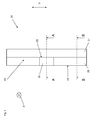
- a hand tool housing 100 is fragmentary in Fig. 1 shown.
- the portable power tool housing 100 has a first housing part 10 and a second housing part 20.
- the first housing part 10 is a housing upper part and the second housing part 20 is a housing lower part.
- the first housing part 10 has an edge 11, which is oriented downwards in the illustrated embodiment.
- a stepped fold 13 is formed at the edge 11 of the first housing part 10 .
- a second stepped fold 23 is formed.
- the edge 21 of the second devisnfalzes 23 is oriented in the illustrated embodiment, upwards.
- the first stepped fold 13 and the second stepped fold 23 are formed complementary to each other. In this way, the first housing part 10 and the second housing part 20 can be assembled in a composition direction Z.
- a groove 15 is formed at the edge 11 of the first housing part 10.
- a spring 25 is formed at the edge 21 of the second housing part 20, a spring 25 is formed.
- Groove 15 and spring 25 form a tongue and groove connection.
- the tongue and groove connection 15, 25 is transversely to the direction of composition Z positively.
- the transverse direction Q which is characterized by the directional arrow, is in the present case oriented perpendicular to the composition direction Z. In other words, the first housing part 10 and the second housing part 20 when they are assembled, not in the transverse direction Q against each other movable.
- the height H of the groove 15 and the spring 25 are greater than the rebate height F of the first stepped rebate 13 and the second stepped rebate 23 in the assembly direction Z.
- the groove 15 is provided on the longer in the direction of assembly Z section 17 of the first devisnfalzes 13.
- the shorter section 18 of the first stepped fold 13 lying next to the longer section 17 is free of a groove.
- the spring 25 is provided on the shorter in the direction of assembly Z section 28 of the second devisnfalzes 23. More specifically, the spring 25 is formed in the present embodiment illustrated on the shorter portion 28 of the second stepped rabbet 23.
- the longer portion 27 of the second stepped rebate 23 remains in the assembly direction Z free of a spring.
- the groove 15, together with the longer portion 17 of the first devisnfalzes 13 a first Maustinum 19.
- the spring 25 forms a second Maustinumnfalz 29 together with a longer in the assembly direction Z longer portion 27 of the second devisnfalzes 23.
- the first Maustinumnfalz 19 and the second Maumenfalz 29th are complementary to each other, which leads to a particularly secure cohesion of the first housing part 10 and the second housing part 20.
- the groove 15 and the spring 25 a height-width ratio of about 1: 1, wherein the reference H denotes the parallel to the composition direction Z oriented height of the groove 15 and the spring 25 and wherein the reference B is perpendicular to Composition direction Z oriented width B of the groove 15 and the spring 25 respectively.
- a surface OF of the first housing part 10 and the second housing part 20, which is directed in the assembled state of the power tool housing 100 in the direction of the housing inner side, is also in Fig. 1 designated.
- the groove 15 and the spring 25 are thus arranged on the respective edges 11, 21, that they are not visible from outside the portable power tool housing 100, ie in the present case from behind, when the first housing part 10 and the second housing part 20 are assembled.
- Fig. 2 shows a plan view of the in Fig. 1 illustrated second (lower) housing part 20. Perpendicular to the transverse direction Q is a section line A - A, which extends through the spring 25 shown. A section line B - B passes through a portion of the second housing part 20, which is free of a spring. Again Fig. 2 can be removed, the shorter portion 28 of the second devisnfalzes 23 is equipped with the spring 25, whereas the longer portion 27 of the second devisnfalzes 23 remains without spring.
- the second Crowstich 29 is formed between the spring 25 and in the assembly direction Z (shown by an arrow pointing in the plane of the paper) longer portion 27 of the second stepped fold 23.
- Fig. 3 is now the section A - A of the second (lower) housing part 20 of the Fig. 2 shown. Again Fig. 3 can be removed, the second Maustinumnfalz 29 is formed identically with respect to groove 25 and longer portion 27.
- Fig. 4 shows a sectional view B - B of the second housing part 20 according to the in Fig. 2 drawn cut line B - B.
- the second stepped rebate 23 starts from the surface OF, which is oriented to the interior of the housing.
- the width of the longer portion 27 and the shorter portion 28 of the second stepped rabbet 23 are approximately the same width in the illustrated embodiment.
- the spring 25 extends over the entire width of the shorter portion 28 of the second Maustichnfalzes 23rd
- both the first housing part 10 and the second housing part 20 are free of Reinforcement struts and reinforcing webs, which protrude from the surface OF of the first housing part 10 and the second housing part 20. This applies both in the direction of the surface normal of the surface OF perpendicular to the composition direction Z and in terms of an outward projection over the edges 11, 21 parallel to the composition direction Z. This applies, of course, with the exception of the spring 25 according to the invention.
Landscapes
- Engineering & Computer Science (AREA)
- Mechanical Engineering (AREA)
- Battery Mounting, Suspending (AREA)
- Portable Power Tools In General (AREA)
- Toys (AREA)
- Connector Housings Or Holding Contact Members (AREA)
- Casings For Electric Apparatus (AREA)
Priority Applications (5)
| Application Number | Priority Date | Filing Date | Title |
|---|---|---|---|
| EP15169325.6A EP3098030A1 (fr) | 2015-05-27 | 2015-05-27 | Carcasse de machine-outil portative |
| PCT/EP2016/061398 WO2016188891A1 (fr) | 2015-05-27 | 2016-05-20 | Carter de machine-outil portative |
| US15/575,259 US10675746B2 (en) | 2015-05-27 | 2016-05-20 | Hand-held power tool housing |
| CN201680015714.7A CN107405767A (zh) | 2015-05-27 | 2016-05-20 | 手持式工具设备壳体 |
| EP16725473.9A EP3302889B1 (fr) | 2015-05-27 | 2016-05-20 | Carcasse de machine-outil portative |
Applications Claiming Priority (1)
| Application Number | Priority Date | Filing Date | Title |
|---|---|---|---|
| EP15169325.6A EP3098030A1 (fr) | 2015-05-27 | 2015-05-27 | Carcasse de machine-outil portative |
Publications (1)
| Publication Number | Publication Date |
|---|---|
| EP3098030A1 true EP3098030A1 (fr) | 2016-11-30 |
Family
ID=53373260
Family Applications (2)
| Application Number | Title | Priority Date | Filing Date |
|---|---|---|---|
| EP15169325.6A Withdrawn EP3098030A1 (fr) | 2015-05-27 | 2015-05-27 | Carcasse de machine-outil portative |
| EP16725473.9A Active EP3302889B1 (fr) | 2015-05-27 | 2016-05-20 | Carcasse de machine-outil portative |
Family Applications After (1)
| Application Number | Title | Priority Date | Filing Date |
|---|---|---|---|
| EP16725473.9A Active EP3302889B1 (fr) | 2015-05-27 | 2016-05-20 | Carcasse de machine-outil portative |
Country Status (4)
| Country | Link |
|---|---|
| US (1) | US10675746B2 (fr) |
| EP (2) | EP3098030A1 (fr) |
| CN (1) | CN107405767A (fr) |
| WO (1) | WO2016188891A1 (fr) |
Families Citing this family (1)
| Publication number | Priority date | Publication date | Assignee | Title |
|---|---|---|---|---|
| CN108193777A (zh) * | 2018-02-25 | 2018-06-22 | 陈贵 | 拼接式穹顶房 |
Citations (6)
| Publication number | Priority date | Publication date | Assignee | Title |
|---|---|---|---|---|
| DE4226903A1 (de) * | 1992-08-14 | 1994-02-17 | Bosch Gmbh Robert | Handwerkzeugmaschine |
| DE20000230U1 (de) * | 2000-01-10 | 2001-05-23 | Robert Bosch Gmbh, 70469 Stuttgart | Elektrische Handwerkzeugmaschine, insbesondere Winkelschleifer |
| JP2002254340A (ja) * | 2001-03-02 | 2002-09-10 | Hitachi Koki Co Ltd | 電動工具 |
| US20120152068A1 (en) * | 2010-12-15 | 2012-06-21 | Yi Feng Liu | Hand tool set combination |
| US20130081838A1 (en) * | 2011-09-30 | 2013-04-04 | Greenlee Textron Inc. | Handle For A Hydraulically Driven Tool With Heat Transmission Reducing Properties |
| DE102013202160A1 (de) * | 2013-02-11 | 2014-08-14 | Robert Bosch Gmbh | Werkzeugmaschinengehäuse |
Family Cites Families (14)
| Publication number | Priority date | Publication date | Assignee | Title |
|---|---|---|---|---|
| DE3312176A1 (de) * | 1983-04-02 | 1984-10-04 | Heinrich C. 4300 Essen Kosmeier | Zweiteiliger behaelter |
| DE3901728C2 (de) * | 1989-01-21 | 1994-10-13 | Atlas Copco Elektrowerkzeuge | Schraubfreie Verbindung der Handgriffschalen eines zweischaligen Gehäuses für ein Elektrowerkzeug |
| DE4428892A1 (de) * | 1994-08-18 | 1996-02-22 | Braun Ag | Epilationsgerät mit einem mehrschaligen Gehäuse |
| JP2638750B2 (ja) * | 1994-10-13 | 1997-08-06 | リョービ株式会社 | 電動工具のハンドル構造 |
| JPH08126977A (ja) * | 1994-10-28 | 1996-05-21 | Hitachi Koki Co Ltd | 携帯用電動工具 |
| US6350124B1 (en) * | 1999-10-22 | 2002-02-26 | Eric Wade | Prophylactic systems for dental instruments and methods for using the same |
| JP2002254240A (ja) | 2001-02-23 | 2002-09-10 | Amada Co Ltd | 帯鋸盤 |
| US7103980B2 (en) * | 2004-04-15 | 2006-09-12 | Clio Designs Incorporated | Integrated shaver and hair trimmer device with adjustable handle |
| DE102004042086A1 (de) * | 2004-08-31 | 2006-03-02 | BSH Bosch und Siemens Hausgeräte GmbH | Haushaltsgerät mit Rast- und Gegenrastmitteln |
| JP4990172B2 (ja) * | 2008-01-24 | 2012-08-01 | パナソニック株式会社 | 電気機器 |
| CN201220408Y (zh) * | 2008-06-12 | 2009-04-15 | 黄金潭 | 具有工具头承置座的握柄 |
| US20100024183A1 (en) * | 2008-06-30 | 2010-02-04 | Cuprys Lawrence M | Removable tool for a display assembly |
| DE102011081661B4 (de) * | 2011-08-26 | 2023-11-30 | Robert Bosch Gmbh | Schaltbares Getriebe für eine Handwerkzeugmaschine |
| CN103370169A (zh) * | 2011-12-30 | 2013-10-23 | 坎贝尔·豪斯费尔德/斯科特·费策尔公司 | 手持式工具及其部件 |
-
2015
- 2015-05-27 EP EP15169325.6A patent/EP3098030A1/fr not_active Withdrawn
-
2016
- 2016-05-20 WO PCT/EP2016/061398 patent/WO2016188891A1/fr not_active Ceased
- 2016-05-20 CN CN201680015714.7A patent/CN107405767A/zh active Pending
- 2016-05-20 US US15/575,259 patent/US10675746B2/en active Active
- 2016-05-20 EP EP16725473.9A patent/EP3302889B1/fr active Active
Patent Citations (6)
| Publication number | Priority date | Publication date | Assignee | Title |
|---|---|---|---|---|
| DE4226903A1 (de) * | 1992-08-14 | 1994-02-17 | Bosch Gmbh Robert | Handwerkzeugmaschine |
| DE20000230U1 (de) * | 2000-01-10 | 2001-05-23 | Robert Bosch Gmbh, 70469 Stuttgart | Elektrische Handwerkzeugmaschine, insbesondere Winkelschleifer |
| JP2002254340A (ja) * | 2001-03-02 | 2002-09-10 | Hitachi Koki Co Ltd | 電動工具 |
| US20120152068A1 (en) * | 2010-12-15 | 2012-06-21 | Yi Feng Liu | Hand tool set combination |
| US20130081838A1 (en) * | 2011-09-30 | 2013-04-04 | Greenlee Textron Inc. | Handle For A Hydraulically Driven Tool With Heat Transmission Reducing Properties |
| DE102013202160A1 (de) * | 2013-02-11 | 2014-08-14 | Robert Bosch Gmbh | Werkzeugmaschinengehäuse |
Also Published As
| Publication number | Publication date |
|---|---|
| US20180133885A1 (en) | 2018-05-17 |
| CN107405767A (zh) | 2017-11-28 |
| EP3302889B1 (fr) | 2019-05-01 |
| WO2016188891A1 (fr) | 2016-12-01 |
| EP3302889A1 (fr) | 2018-04-11 |
| US10675746B2 (en) | 2020-06-09 |
Similar Documents
| Publication | Publication Date | Title |
|---|---|---|
| DE102013015179A1 (de) | Wärmetauscheranordnung und Herstellungsverfahren | |
| EP3219917B1 (fr) | Agencement d'aubes de turbomachine, turbomachine et procédé de fabrication associés | |
| EP3106823A1 (fr) | Échangeur de chaleur | |
| DE102011053720A1 (de) | Sägeblatt mit Leistungszähnen und Oberflächenzähnen | |
| WO2017005239A1 (fr) | Module solaire | |
| EP3302889B1 (fr) | Carcasse de machine-outil portative | |
| DE2162381A1 (de) | Eckverbinder fuer doppel-hohlprofilstreben | |
| DE19822772C2 (de) | Metallische Mehrlagenflachdichtung | |
| EP1288435A2 (fr) | Aube de turbine avec au moins un orifice de refroidissement | |
| DE202012002498U1 (de) | Tür, Metallkonstruktionsprofil einer Zarge oder eines Rahmens für eine Tür oder ein Fenster | |
| DE102007027706A1 (de) | Wärmetauscher | |
| DE20306407U1 (de) | Doppelwand-Wellrohr | |
| DE202017102919U1 (de) | Ringförmige Dichtung | |
| AT508417A2 (de) | Geschossfangvorrichtung | |
| DE102019133501B4 (de) | Spoilerblatt, Spoileranordnung und Kraftfahrzeug | |
| DE102007032973B4 (de) | Y-förmige Kühlrippenanordnung | |
| EP3409909B1 (fr) | Boîtier intermédiaire de turbine comprenant un élément de centrage et écarteur | |
| EP3363994B1 (fr) | Agencement d'étanchéité pour une turbine à gaz | |
| DE102014204504A1 (de) | Formwerkzeug mit optimierten Klemmleisten zur dreidimensionalen Verformung eines Fasermattenzuschnitts | |
| EP2772700A1 (fr) | Grille de guidage d'air de ventilation destinée à être disposée dans une entrée d'air et/ou dans une sortie d'air d'une installation de climatisation et de ventilation | |
| EP2592359B9 (fr) | Clapet coupe-feu doté d'un boîtier et d'un clapet d'arrêt installé à l'intérieur de celui-ci et pivotant autour d'un axe de pivotement, notamment au centre de celui-ci | |
| DE102004016068B4 (de) | Eckwinkel für eine Flanschverbindung von Klimatisierungskanälen | |
| EP4062994B9 (fr) | Procédé de montage d'une cellule filtrante pour une installation technique d'air ambiant | |
| DE10217389A1 (de) | Turbinenschaufel | |
| DE597378C (de) | Irisblende |
Legal Events
| Date | Code | Title | Description |
|---|---|---|---|
| PUAI | Public reference made under article 153(3) epc to a published international application that has entered the european phase |
Free format text: ORIGINAL CODE: 0009012 |
|
| AK | Designated contracting states |
Kind code of ref document: A1 Designated state(s): AL AT BE BG CH CY CZ DE DK EE ES FI FR GB GR HR HU IE IS IT LI LT LU LV MC MK MT NL NO PL PT RO RS SE SI SK SM TR |
|
| AX | Request for extension of the european patent |
Extension state: BA ME |
|
| STAA | Information on the status of an ep patent application or granted ep patent |
Free format text: STATUS: THE APPLICATION IS DEEMED TO BE WITHDRAWN |
|
| 18D | Application deemed to be withdrawn |
Effective date: 20170531 |