EP3098431A1 - Gasmotor - Google Patents
Gasmotor Download PDFInfo
- Publication number
- EP3098431A1 EP3098431A1 EP15739811.6A EP15739811A EP3098431A1 EP 3098431 A1 EP3098431 A1 EP 3098431A1 EP 15739811 A EP15739811 A EP 15739811A EP 3098431 A1 EP3098431 A1 EP 3098431A1
- Authority
- EP
- European Patent Office
- Prior art keywords
- air supply
- opening degree
- air
- target
- gas
- Prior art date
- Legal status (The legal status is an assumption and is not a legal conclusion. Google has not performed a legal analysis and makes no representation as to the accuracy of the status listed.)
- Withdrawn
Links
Images




Classifications
-
- F—MECHANICAL ENGINEERING; LIGHTING; HEATING; WEAPONS; BLASTING
- F02—COMBUSTION ENGINES; HOT-GAS OR COMBUSTION-PRODUCT ENGINE PLANTS
- F02D—CONTROLLING COMBUSTION ENGINES
- F02D41/00—Electrical control of supply of combustible mixture or its constituents
- F02D41/0025—Controlling engines characterised by use of non-liquid fuels, pluralities of fuels, or non-fuel substances added to the combustible mixtures
- F02D41/0027—Controlling engines characterised by use of non-liquid fuels, pluralities of fuels, or non-fuel substances added to the combustible mixtures the fuel being gaseous
-
- B—PERFORMING OPERATIONS; TRANSPORTING
- B63—SHIPS OR OTHER WATERBORNE VESSELS; RELATED EQUIPMENT
- B63H—MARINE PROPULSION OR STEERING
- B63H21/00—Use of propulsion power plant or units on vessels
- B63H21/12—Use of propulsion power plant or units on vessels the vessels being motor-driven
- B63H21/14—Use of propulsion power plant or units on vessels the vessels being motor-driven relating to internal-combustion engines
-
- B—PERFORMING OPERATIONS; TRANSPORTING
- B63—SHIPS OR OTHER WATERBORNE VESSELS; RELATED EQUIPMENT
- B63H—MARINE PROPULSION OR STEERING
- B63H21/00—Use of propulsion power plant or units on vessels
- B63H21/12—Use of propulsion power plant or units on vessels the vessels being motor-driven
- B63H21/17—Use of propulsion power plant or units on vessels the vessels being motor-driven by electric motor
-
- F—MECHANICAL ENGINEERING; LIGHTING; HEATING; WEAPONS; BLASTING
- F02—COMBUSTION ENGINES; HOT-GAS OR COMBUSTION-PRODUCT ENGINE PLANTS
- F02B—INTERNAL-COMBUSTION PISTON ENGINES; COMBUSTION ENGINES IN GENERAL
- F02B29/00—Engines characterised by provision for charging or scavenging not provided for in groups F02B25/00, F02B27/00 or F02B33/00 - F02B39/00; Details thereof
- F02B29/04—Cooling of air intake supply
- F02B29/0406—Layout of the intake air cooling or coolant circuit
- F02B29/0437—Liquid cooled heat exchangers
-
- F—MECHANICAL ENGINEERING; LIGHTING; HEATING; WEAPONS; BLASTING
- F02—COMBUSTION ENGINES; HOT-GAS OR COMBUSTION-PRODUCT ENGINE PLANTS
- F02B—INTERNAL-COMBUSTION PISTON ENGINES; COMBUSTION ENGINES IN GENERAL
- F02B37/00—Engines characterised by provision of pumps driven at least for part of the time by exhaust
- F02B37/12—Control of the pumps
- F02B37/16—Control of the pumps by bypassing charging air
-
- F—MECHANICAL ENGINEERING; LIGHTING; HEATING; WEAPONS; BLASTING
- F02—COMBUSTION ENGINES; HOT-GAS OR COMBUSTION-PRODUCT ENGINE PLANTS
- F02B—INTERNAL-COMBUSTION PISTON ENGINES; COMBUSTION ENGINES IN GENERAL
- F02B43/00—Engines characterised by operating on gaseous fuels; Plants including such engines
-
- F—MECHANICAL ENGINEERING; LIGHTING; HEATING; WEAPONS; BLASTING
- F02—COMBUSTION ENGINES; HOT-GAS OR COMBUSTION-PRODUCT ENGINE PLANTS
- F02B—INTERNAL-COMBUSTION PISTON ENGINES; COMBUSTION ENGINES IN GENERAL
- F02B61/00—Adaptations of engines for driving vehicles or for driving propellers; Combinations of engines with gearing
- F02B61/04—Adaptations of engines for driving vehicles or for driving propellers; Combinations of engines with gearing for driving propellers
-
- F—MECHANICAL ENGINEERING; LIGHTING; HEATING; WEAPONS; BLASTING
- F02—COMBUSTION ENGINES; HOT-GAS OR COMBUSTION-PRODUCT ENGINE PLANTS
- F02D—CONTROLLING COMBUSTION ENGINES
- F02D19/00—Controlling engines characterised by their use of non-liquid fuels, pluralities of fuels, or non-fuel substances added to the combustible mixtures
- F02D19/02—Controlling engines characterised by their use of non-liquid fuels, pluralities of fuels, or non-fuel substances added to the combustible mixtures peculiar to engines working with gaseous fuels
-
- F—MECHANICAL ENGINEERING; LIGHTING; HEATING; WEAPONS; BLASTING
- F02—COMBUSTION ENGINES; HOT-GAS OR COMBUSTION-PRODUCT ENGINE PLANTS
- F02D—CONTROLLING COMBUSTION ENGINES
- F02D19/00—Controlling engines characterised by their use of non-liquid fuels, pluralities of fuels, or non-fuel substances added to the combustible mixtures
- F02D19/02—Controlling engines characterised by their use of non-liquid fuels, pluralities of fuels, or non-fuel substances added to the combustible mixtures peculiar to engines working with gaseous fuels
- F02D19/021—Control of components of the fuel supply system
- F02D19/023—Control of components of the fuel supply system to adjust the fuel mass or volume flow
- F02D19/024—Control of components of the fuel supply system to adjust the fuel mass or volume flow by controlling fuel injectors
-
- F—MECHANICAL ENGINEERING; LIGHTING; HEATING; WEAPONS; BLASTING
- F02—COMBUSTION ENGINES; HOT-GAS OR COMBUSTION-PRODUCT ENGINE PLANTS
- F02D—CONTROLLING COMBUSTION ENGINES
- F02D23/00—Controlling engines characterised by their being supercharged
-
- F—MECHANICAL ENGINEERING; LIGHTING; HEATING; WEAPONS; BLASTING
- F02—COMBUSTION ENGINES; HOT-GAS OR COMBUSTION-PRODUCT ENGINE PLANTS
- F02D—CONTROLLING COMBUSTION ENGINES
- F02D29/00—Controlling engines, such controlling being peculiar to the devices driven thereby, the devices being other than parts or accessories essential to engine operation, e.g. controlling of engines by signals external thereto
- F02D29/06—Controlling engines, such controlling being peculiar to the devices driven thereby, the devices being other than parts or accessories essential to engine operation, e.g. controlling of engines by signals external thereto peculiar to engines driving electric generators
-
- F—MECHANICAL ENGINEERING; LIGHTING; HEATING; WEAPONS; BLASTING
- F02—COMBUSTION ENGINES; HOT-GAS OR COMBUSTION-PRODUCT ENGINE PLANTS
- F02D—CONTROLLING COMBUSTION ENGINES
- F02D41/00—Electrical control of supply of combustible mixture or its constituents
- F02D41/0002—Controlling intake air
- F02D41/0007—Controlling intake air for control of turbo-charged or super-charged engines
-
- F—MECHANICAL ENGINEERING; LIGHTING; HEATING; WEAPONS; BLASTING
- F02—COMBUSTION ENGINES; HOT-GAS OR COMBUSTION-PRODUCT ENGINE PLANTS
- F02D—CONTROLLING COMBUSTION ENGINES
- F02D41/00—Electrical control of supply of combustible mixture or its constituents
- F02D41/30—Controlling fuel injection
- F02D41/32—Controlling fuel injection of the low pressure type
- F02D41/34—Controlling fuel injection of the low pressure type with means for controlling injection timing or duration
-
- F—MECHANICAL ENGINEERING; LIGHTING; HEATING; WEAPONS; BLASTING
- F02—COMBUSTION ENGINES; HOT-GAS OR COMBUSTION-PRODUCT ENGINE PLANTS
- F02M—SUPPLYING COMBUSTION ENGINES IN GENERAL WITH COMBUSTIBLE MIXTURES OR CONSTITUENTS THEREOF
- F02M21/00—Apparatus for supplying engines with non-liquid fuels, e.g. gaseous fuels stored in liquid form
- F02M21/02—Apparatus for supplying engines with non-liquid fuels, e.g. gaseous fuels stored in liquid form for gaseous fuels
- F02M21/0203—Apparatus for supplying engines with non-liquid fuels, e.g. gaseous fuels stored in liquid form for gaseous fuels characterised by the type of gaseous fuel
- F02M21/0215—Mixtures of gaseous fuels; Natural gas; Biogas; Mine gas; Landfill gas
-
- F—MECHANICAL ENGINEERING; LIGHTING; HEATING; WEAPONS; BLASTING
- F02—COMBUSTION ENGINES; HOT-GAS OR COMBUSTION-PRODUCT ENGINE PLANTS
- F02M—SUPPLYING COMBUSTION ENGINES IN GENERAL WITH COMBUSTIBLE MIXTURES OR CONSTITUENTS THEREOF
- F02M21/00—Apparatus for supplying engines with non-liquid fuels, e.g. gaseous fuels stored in liquid form
- F02M21/02—Apparatus for supplying engines with non-liquid fuels, e.g. gaseous fuels stored in liquid form for gaseous fuels
- F02M21/0218—Details on the gaseous fuel supply system, e.g. tanks, valves, pipes, pumps, rails, injectors or mixers
- F02M21/0248—Injectors
- F02M21/0278—Port fuel injectors for single or multipoint injection into the air intake system
-
- F—MECHANICAL ENGINEERING; LIGHTING; HEATING; WEAPONS; BLASTING
- F02—COMBUSTION ENGINES; HOT-GAS OR COMBUSTION-PRODUCT ENGINE PLANTS
- F02M—SUPPLYING COMBUSTION ENGINES IN GENERAL WITH COMBUSTIBLE MIXTURES OR CONSTITUENTS THEREOF
- F02M21/00—Apparatus for supplying engines with non-liquid fuels, e.g. gaseous fuels stored in liquid form
- F02M21/02—Apparatus for supplying engines with non-liquid fuels, e.g. gaseous fuels stored in liquid form for gaseous fuels
- F02M21/04—Gas-air mixing apparatus
-
- F—MECHANICAL ENGINEERING; LIGHTING; HEATING; WEAPONS; BLASTING
- F02—COMBUSTION ENGINES; HOT-GAS OR COMBUSTION-PRODUCT ENGINE PLANTS
- F02D—CONTROLLING COMBUSTION ENGINES
- F02D41/00—Electrical control of supply of combustible mixture or its constituents
- F02D41/02—Circuit arrangements for generating control signals
- F02D41/14—Introducing closed-loop corrections
- F02D41/1401—Introducing closed-loop corrections characterised by the control or regulation method
- F02D2041/1412—Introducing closed-loop corrections characterised by the control or regulation method using a predictive controller
-
- F—MECHANICAL ENGINEERING; LIGHTING; HEATING; WEAPONS; BLASTING
- F02—COMBUSTION ENGINES; HOT-GAS OR COMBUSTION-PRODUCT ENGINE PLANTS
- F02D—CONTROLLING COMBUSTION ENGINES
- F02D2250/00—Engine control related to specific problems or objectives
- F02D2250/31—Control of the fuel pressure
-
- Y—GENERAL TAGGING OF NEW TECHNOLOGICAL DEVELOPMENTS; GENERAL TAGGING OF CROSS-SECTIONAL TECHNOLOGIES SPANNING OVER SEVERAL SECTIONS OF THE IPC; TECHNICAL SUBJECTS COVERED BY FORMER USPC CROSS-REFERENCE ART COLLECTIONS [XRACs] AND DIGESTS
- Y02—TECHNOLOGIES OR APPLICATIONS FOR MITIGATION OR ADAPTATION AGAINST CLIMATE CHANGE
- Y02T—CLIMATE CHANGE MITIGATION TECHNOLOGIES RELATED TO TRANSPORTATION
- Y02T10/00—Road transport of goods or passengers
- Y02T10/10—Internal combustion engine [ICE] based vehicles
- Y02T10/12—Improving ICE efficiencies
-
- Y—GENERAL TAGGING OF NEW TECHNOLOGICAL DEVELOPMENTS; GENERAL TAGGING OF CROSS-SECTIONAL TECHNOLOGIES SPANNING OVER SEVERAL SECTIONS OF THE IPC; TECHNICAL SUBJECTS COVERED BY FORMER USPC CROSS-REFERENCE ART COLLECTIONS [XRACs] AND DIGESTS
- Y02—TECHNOLOGIES OR APPLICATIONS FOR MITIGATION OR ADAPTATION AGAINST CLIMATE CHANGE
- Y02T—CLIMATE CHANGE MITIGATION TECHNOLOGIES RELATED TO TRANSPORTATION
- Y02T10/00—Road transport of goods or passengers
- Y02T10/10—Internal combustion engine [ICE] based vehicles
- Y02T10/30—Use of alternative fuels, e.g. biofuels
-
- Y—GENERAL TAGGING OF NEW TECHNOLOGICAL DEVELOPMENTS; GENERAL TAGGING OF CROSS-SECTIONAL TECHNOLOGIES SPANNING OVER SEVERAL SECTIONS OF THE IPC; TECHNICAL SUBJECTS COVERED BY FORMER USPC CROSS-REFERENCE ART COLLECTIONS [XRACs] AND DIGESTS
- Y02—TECHNOLOGIES OR APPLICATIONS FOR MITIGATION OR ADAPTATION AGAINST CLIMATE CHANGE
- Y02T—CLIMATE CHANGE MITIGATION TECHNOLOGIES RELATED TO TRANSPORTATION
- Y02T70/00—Maritime or waterways transport
- Y02T70/50—Measures to reduce greenhouse gas emissions related to the propulsion system
- Y02T70/5218—Less carbon-intensive fuels, e.g. natural gas, biofuels
Definitions
- the present invention relates to a gas engine.
- a gas engine using a fuel gas such as natural gas and town gas as fuel, in which a ratio between a flow rate of outside atmospheric air (supply air) and a flow rate of the fuel gas (hereinafter, the ratio will simply be referred to as an "air-fuel ratio”) is adjusted so as to achieve an optimum ratio according to properties of the fuel gas to be used, in order to maintain an adequate combustion state and to suppress NOx or the like contained in exhaust gas.
- a ratio between a flow rate of outside atmospheric air (supply air) and a flow rate of the fuel gas hereinafter, the ratio will simply be referred to as an "air-fuel ratio”
- a target fuel gas flow rate determined from a target rotational speed and power output, and a target air supply amount determined based on the optimum air-fuel ratio are calculated.
- a target opening degree of an air supply valve which serves as a benchmark reference, is calculated from an air supply amount, and a target opening degree of a throttle valve is corrected based on a deviation between the target air supply amount and an actual air supply amount.
- Patent Document 1 is a diagrammatic representation of Patent Document 1
- a target opening degree of a throttle valve is corrected based on a deviation between a target air supply amount and an actual air supply amount in order to maintain an air-fuel ratio at an adequate value. Consequently, when a load fluctuation occurs, a supply amount of the supply air having a low response speed to an increase in the injection amount of the fuel gas fails to follow the increase in the injection amount of the fuel gas, and the air-fuel ratio fluctuates in some cases.
- Patent Document 1 JP-A 2009-57873 Gazette
- the present invention is conceived in order to solve such a problem, and an object thereof is to provide a gas engine capable of suppressing a fluctuation of an air-fuel ratio even when a load fluctuation occurs.
- a target gas pressure and a target gas injection time of a fuel gas are calculated based on a load fluctuation, a gas pressure is corrected based on the target gas pressure, and at least one of the opening degree of the air supply valve and the opening degree of the bypass valve is corrected based on amounts of variations in the target gas pressure and the target gas injection time.
- a target gas pressure is calculated based on a load fluctuation
- a gas pressure is corrected based on the target gas pressure
- a predicted load after a unit time is calculated based on a load fluctuation pattern in a predetermined period up to the present current time
- at least one of the opening degree of the air supply valve and the opening degree of the bypass valve is corrected based on the predicted load.
- a predicted load after a unit time is calculated based on a load fluctuation pattern in a predetermined period up to the present current time, and a target air supply pressure or a target air-fuel ratio is collected based on the predicted load.
- At least one of the opening degree of the air supply valve and the opening degree of the bypass valve is corrected based on a pressure difference between the target air supply pressure and an actual air supply pressure, or a difference between the target air-fuel ratio and an actual air-fuel ratio.
- an opening degree of an air supply valve and an opening degree of a bypass valve is corrected based on variation in a target gas pressure and a target gas injection time of a fuel gas having a high response speed, a response speed of an air supply pressure improves. Thus, it is possible to suppress a fluctuation of an air-fuel ratio associated with a fluctuation of a load rate.
- the present invention since in addition to the correction of at least one of the opening degree of the air supply valve and the opening degree of the bypass valve based on the variation in the target gas pressure and the target gas injection time of the fuel gas having a high response speed, at least one of the opening degree of the air supply valve and the opening degree of the bypass valve is corrected based on a predicted forthcoming load fluctuation, a response speed of an air supply pressure improves. Thus, it is possible to suppress a fluctuation of an air-fuel ratio associated with a load fluctuation.
- the opening degree of the air supply valve and the opening degree of the bypass valve is corrected based on the predicted forthcoming load fluctuation, a deviation between a target air supply pressure and an actual air supply pressure reduces. Thus, it is possible to suppress a fluctuation of an air-fuel ratio associated with a load fluctuation.
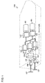
- FIG. 1 is an embodiment of a ship that has gas engines 1 according to the present invention mounted thereon and including superchargers, respectively. Further, FIG. 1 schematically shows a configuration of the electric propulsion ship 100.
- the electric propulsion ship 100 has the gas engines 1 according to the embodiment.
- the electric propulsion ship 100 includes LNG tanks 101, vaporizers 102, the gas engines 1, electric generators 103, a power control board 104, propulsion motors 105, reducers 106, and adjustable pitch-propellers 107.
- a fuel gas stored in the LNG tanks 101-101 is mixed with air by the vaporizers 102-102, and is supplied to the gas engines 1 ⁇ 1 ⁇ 1.
- the electric generators 103 ⁇ 103 ⁇ 103 are driven by the gas engines 1 ⁇ 1 ⁇ 1, and power is supplied to the propulsion motors 105 ⁇ 105 and inboard loads by the power control board 104.
- the drive of the propulsion motors 105 ⁇ 105 is transmitted to the adjustable pitch-propellers 107 ⁇ 107 via the reducers 106 ⁇ 106.
- each of the gas engine 1 includes gas engines 1 that are gas engines using fuel gas such as natural gas as a fuel.
- gas engines 1 that are gas engines using fuel gas such as natural gas as a fuel.
- a main power generation system of the electric propulsion ship is the gas engine in the present embodiment, the usage of the gas engine is not limited thereto, and the gas engine may be used as a main machine or an auxiliary machine in a ship that drives a propeller by an engine.
- an "upstream side” in the present embodiment indicates the upstream side in the flowing direction of gas and air mixture
- a “downstream side” in the present embodiment indicates the downstream side in the flowing direction of gas and air mixture.
- the gas engine 1 is a single cylinder engine or a multicylinder engine, and uses fuel gas such as natural gas as fuel.
- the gas engine 1 according to the present embodiment is mainly a straight-six-cylinder engine having six cylinders 1a. Further, in the embodiment, the gas engine 1 is the straight-six-cylinder engine equipped with a one-stage supercharger, but the gas engine 1 is not limited thereto as long as it is a multicylinder engine equipped with at least one or more supercharger.
- the gas engine 1 rotates and drives an output shaft by mixing and combusting atmospheric air and fuel gas inside each cylinder 1a.
- the gas engine 1 is equipped with an air intake device 2 that takes atmospheric air in, an air exhaust device 11 that discharges exhaust air to the outside, and an ECU 14 that is a control device.
- the gas engine 1 connects to the electric generators 103 (see FIG. 1 ), of which the power output shaft (not shown in FIG.) is a load device.
- the air intake device 2 is equipped with a compressor unit 3a of a supercharger 3, an air supply pipe 4a, an air supply valve 5a, a bypass valve 5b, an intercooler 6, and an air supply manifold 7.
- the supercharger 3 pressurizes and compresses intake air, using an exhaust pressure of exhaust air as a driving source.
- the supercharger 3 includes the compressor unit 3 a and a turbine unit 3b.
- the compressor unit 3a of the supercharger 3 pressurizes and compresses intake-air.
- the compressor unit 3a is coupled to the turbine unit 3b with a connecting shaft 3c.
- the compressor unit 3a is configured such that rotational power from the turbine unit 3b can be transmitted via the connecting shaft 3c.
- the intercooler 6 is coupled to the compressor unit 3a via the air supply pipe 4a.
- supply air the pressurized intake-air after the pressurization and compression by the compressor unit 3a is referred to as supply air.
- the air supply valve 5a changes a flow rate of the supply air (air supply amount).
- the air supply pipe 4a includes the air supply valve 5a.
- the air supply valve 5a is provided in the air supply pipe 4a on the downstream side of the compressor unit 3a of the supercharger 3 and on the upstream side of the intercooler 6. Specifically, the air supply valve 5a is provided between the compressor unit 3a and the intercooler 6.
- the air supply valve 5a includes an automatic valve that is openable and closable by an actuator such as an electronic motor.
- the air supply valve 5a can change the air supply amount to be supplied to the gas engine 1 by adjusting an opening degree D thereof.
- the bypass valve 5b reduces the air supply amount.
- the bypass valve 5b is provided in a bypass pipe 4b that connects the upstream side of the compressor unit 3a of the supercharger 3 and the intercooler 6.
- the air supply valve 5a can discharge the supply air supplied to the intercooler 6 to the upstream side of the compressor unit 3a.
- the bypass valve 5b includes an automatic valve that is openable and closable by an actuator such as an electronic motor.
- the bypass valve 5b can discharge the supply air from the intercooler 6 and change the air supply amount to be supplied to the gas engine 1 by adjusting an opening degree thereof.
- the intercooler 6 cools the pressurized supply air.
- the intercooler 6 cools the supply air by exchanging heat between cooling water supplied by a cooling water pump (not shown) and the pressurized supply air.
- the air supply manifold 7 is connected to the intercooler 6.
- the air supply manifold 7 distributes the supply air to each cylinder 1a of the engine 1.
- the air supply manifold 7 is connected to each cylinder 1a of the gas engine 1 via corresponding one of air supply ports 8.
- the air supply manifold 7 is configured such that the supply air cooled by the intercooler 6 can be supplied to each cylinder 1a of the gas engine 1.
- the air supply manifold 7 is provided with an air supply pressure sensor 9 that senses an actual air supply pressure Pi.
- Each of the air supply ports 8 is provided with a gas injector 8a that injects fuel gas.
- a regulator 10 that is a pressure regulating valve controlling a fuel gas pressure is provided in a fuel gas supplying path (not shown) that supplies fuel gas to each gas injector 8a.
- the air exhaust device 11 discharges exhaust air from the gas engine 1 to the outside.
- the air exhaust device 11 comprises an air exhaust manifold 12 and the turbine unit 3b of the supercharger 3.
- the air exhaust manifold 12 collects exhaust air from each cylinder 1a.
- the air exhaust manifold 12 is connected to each cylinder 1a of the gas engine 1 via corresponding one of air exhaust port 13.
- the air exhaust manifold 12 has another side end portion connected to the supercharger 3.
- the air exhaust manifold 12 is provided with an air-fuel ratio sensor (oxygen sensor) (not shown) that detects a residual oxygen amount O (not shown in FIG.) in the exhaust air, which is used for calculating an actual air-fuel ratio ⁇ .
- oxygen sensor oxygen sensor
- the turbine unit 3b of the supercharger 3 generates rotational power by the pressure of the exhaust air.
- the turbine unit 3b is coupled with the compressor unit 3a by the connecting shaft 3c, and is configured such that the rotational power can be transmitted to the compressor unit 3a.
- the air exhaust manifold 12 is connected to the turbine unit 3b.
- the turbine unit 3b communicates with the outside via a purification system (not shown in FIG.) or the like.
- the compressor unit 3a of the supercharger 3, the air supply pipe 4a, the intercooler 6, and the air supply manifold 7 are connected to the air intake device 2 inorder from the upstream side (outside).
- the air exhaust manifold 12, the turbine unit 3b of the supercharger 3, an exhaust pipe (not shown in FIG.), and the like are connected to the air exhaust device 11 in order from the upstream side (the gas engine 1).
- the ECU 14 that is a control device controls operation of the gas engine 1.
- the ECU 14 stores various programs for controlling the gas engine 1, and data such as a target rotational speed map M1 (not shown in FIG.), a target air supply pressure map M2, a target gas differential pressure map M3, a reference opening degree map M4, and a first opening degree correction map M5.
- the gas pressure difference means a pressure difference between the actual air supply pressure Pi and a target gas pressure Pgt.
- the ECU 14 stores a variety of maps and is configured to perform the control based on these maps, but the configuration of the ECU 14 is not limited thereto.
- the ECU 14 may be configured to calculate each value by an arithmetic expression instead of the maps.
- the ECU 14 may be configured such that a CPU, a ROM, a RAM, an HDD or the like is connected in a bus, or may be configured to include one chip LSI or the like.
- the ECU 14 is connected to the air supply valve 5a and the bypass valve 5b, and the ECU 14 can change the actual air supply pressure Pi by controlling the opening degree D of the air supply valve 5a. That is, the ECU 14 can change the air supply amount to be supplied to the gas engine 1 by controlling the opening degree D of the air supply valve 5a (and/or the opening degree of the bypass valve 5b).
- the ECU 14 is connected to each gas injector 8a, and can change a fuel gas injection time T of the gas injector 8a. That is, the ECU 14 can stop operation of the gas engine 1 and change a fuel gas amount by changing the fuel gas injection time by the gas injector 8a.
- the ECU 14 is connected to the regulator 10, and can change a set pressure Pr of the fuel gas pressure of the regulator 10. That is, the ECU 14 can change the fuel gas amount to be supplied to the gas engine 1 by controlling the set pressure Pr of the regulator 10.
- the ECU 14 is connected to the air supply pressure sensor 9, and can acquire the actual air supply pressure Pi detected by the air supply pressure sensor 9.
- the ECU 14 is connected to a gas pressure sensor 15, and can acquire an actual gas pressure Pg (not shown in FIG.) detected by the gas pressure sensor 15.
- the ECU 14 is connected to a rotational speed detection sensor 16, and can acquire an actual rotational speed N of the gas engine 1 detected by the rotational speed detection sensor 16.
- the ECU 14 is connected to an accelerator lever 17 commanding an application of a load, and can acquire a command value C from the accelerator lever 17.
- the ECU 14 is connected to the air-fuel ratio sensor (not shown in FIG.), and can acquire the residual oxygen amount O in the exhaust air detected by the air-fuel ratio sensor.
- the ECU 14 is connected to the electric generator 103, and can acquire an actual load L, based on a power signal from the electric generator 103.
- the ECU 14 can calculate a target rotational speed Nt, based on the target rotational speed map M1 and from the command value C from the accelerator lever 17.
- the ECU 14 can calculate a target air supply pressure Pit, based on the acquired actual load L, a lubricant oil temperature acquired from a lubricant oil temperature sensor (not shown in FIG.), a supply air temperature acquired from a supply air temperature sensor (not shown in FIG.), or the like.
- the ECU 14 can calculate a target gas differential pressure Pgdt, based on the target gas pressure difference map M3 and from the acquired actual load L.
- the ECU 14 can calculate a target gas injection time Tt of the gas injector 8a from the acquired actual rotational speed N and the calculated target rotational speed Nt.
- the ECU 14 can calculate a reference opening degree D0 of the air supply valve 5a (or at least one of the air supply valve 5a and the bypass valve 5b), based on the reference opening degree map M4 and from a deviation between the acquired actual air supply pressure Pi and the calculated target air supply pressure Pit.
- the ECU 14 can calculate a first corrected opening degree ⁇ D1 of at least either one of the air supply valve 5a or the bypass valve 5b, based on the first opening degree correction map M5 and from amounts of change in the acquired target gas pressure difference Pgdt and the target gas injection time Tt.
- the ECU 14 can calculate the target gas pressure Pgt from the acquired actual air supply pressure Pi and the calculated target gas pressure difference Pgdt.
- the ECU 14 can change the injection time T of the gas injector 8a to the calculated target gas injection time Tt.
- the ECU 14 can calculate a target air-fuel ratio ⁇ t, based on a target air-fuel ratio map (not shown in FIG.) and from the acquired actual load L.
- the ECU 14 can calculate the actual air-fuel ratio ⁇ from the acquired residual oxygen amount O.
- the ECU 14 can change the current set pressure Pr of the regulator 10 to the calculated target gas pressure Pgt.
- the air intake device 2 is basically configured such that the opening degree of at least either one of the air supply valve 5a or the bypass valve 5b is corrected based on the pressure difference between the target air supply pressure Pit and the actual air supply pressure Pi, but the air intake device 2 may be configured such that the opening degree is corrected based on a difference between the target air-fuel ratio ⁇ t and the actual air-fuel ratio ⁇ .
- outside air suction air
- pressurized and compressed by the compressor unit 3a of the supercharger 3 At this time, compression heat is generated by the pressurization and compression of the intake-air, and a temperature of the intake-air increases.
- the supply air pressurized and compressed by the compressor unit 3a is discharged from the supercharger 3.
- the supply air discharged from the supercharger 3 is supplied to the intercooler 6 via the air supply pipe 4a at a flow rate adjusted by at least either one of the air supply valve 5a or the bypass valve 5b.
- the supply air supplied to the intercooler 6 is cooled and thereafter supplied to the air supply manifold 7.
- some of the supply air supplied to the intercooler 6 is supplied to the supercharger 3 via the bypass pipe 4b at a flow rate adjusted by the bypass valve 5b.
- the supply air supplied to the air supply manifold 7 is supplied to each cylinder 1a of the gas engine 1 via each air supply port 8. At this time, a fuel gas is injected from the gas injector 8a equipped in each air supply port 8, based on the target air supply pressure Pit.
- the exhaust air from the gas engine 1 is supplied to the turbine unit 3b of the supercharger 3 via the air exhaust manifold 8 and the air exhaust manifold 12.
- the turbine unit 3b is rotated by the exhaust air. Rotational power of the turbine unit 3b is transmitted to the compressor unit 3a via the connecting shaft 3c.
- the exhaust air supplied to the turbine unit 3b is discharged outside via a purification system (not shown in FIG.) or the like.
- the ECU 14 calculates the target air supply pressure Pit from the actual load L.
- the ECU 14 calculates the reference opening degree D0 from the deviation between the target air supply pressure Pit and the actual air supply pressure Pi.
- the ECU 14 calculates the first corrected opening degree ⁇ D1 from the amounts of change in the target gas pressure difference Pgdt and the target gas injection time Tt.
- the ECU 14 changes the opening degree D of at least either one of the air supply valve 5a or the bypass valve 5b on the basis of the reference opening degree D0 and the first corrected opening degree ⁇ D1.
- the ECU 14 corrects the air supply amount.
- the ECU 14 changes the set pressure Pr of the regulator 10 to the target gas pressure Pgt, and changes the injection time T of the gas injector 8a to the target gas injection time Tt.
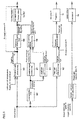
- the ECU 14 acquires the actual air supply pressure Pi detected by the air supply pressure sensor 9, the actual rotational speed N of the gas engine 1 detected by the rotational speed detection sensor 16, the actual load L detected by the electric generator 103, and the command value C from the accelerator lever 17, and the step proceeds to the step S120.
- step S120 the ECU 14 calculates the target rotational speed Nt from the acquired command value C, and the step proceeds to the step S130.
- step S130 the ECU 14 calculates the target air supply pressure Pit from the acquired actual load L, and the step proceeds to the step S140.
- step S140 the ECU 14 calculates the target gas pressure difference Pgdt from the acquired actual load L, and the step proceeds to the step S150.
- step S150 the ECU 14 calculates the target gas injection time Tt from the acquired actual rotational speed N and the calculated target rotational speed Nt, and the step proceeds to the step S160.
- step S160 the ECU 14 calculates the reference opening degree D0 from the deviation between the acquired actual air supply pressure Pi and the calculated target air supply pressure Pit, and the step proceeds to the step S170.
- the ECU 14 calculates the first corrected opening degree ⁇ D1 from the amounts of change in the calculated target gas pressure difference Pgdt and the calculated target gas injection time Tt, and the step proceeds to the step S180.
- step S180 the ECU 14 calculates the target gas pressure Pgt from the acquired actual air supply pressure Pi and the calculated target gas pressure difference Pgdt, and the step proceeds to the step S190.
- the opening degree D of at least either one of the air supply valve 5a or the bypass valve 5b is changed based on the reference opening degree D0 calculated from the deviation between the actual air supply pressure Pi and the target air supply pressure Pit, and based on the first corrected opening degree ⁇ D1 calculated from the amounts of change in the target gas pressure difference Pgdt and the target gas injection time Tt.
- the opening degree D of the air supply valve i.e., the air supply amount is corrected based on the changes in the target gas pressure difference Pgdt and the target gas injection time Tt of fuel gas having a high response speed
- a response speed of the actual air supply pressure Pi improves.
- FIGs. 5 and 6 a gas engine 19 that is a second embodiment of the gas engine according to the present invention will be described with reference to FIGs. 5 and 6 . Further, in the following embodiment, specific description related to points similar to the description in the embodiment described above will be omitted, and different points will be described mainly.
- An ECU 14 stores a variety of programs for controlling a gas engine 19, and data such as a load prediction map M6, a predicted target injection map M7, and a second opening degree correction map M8.
- the ECU 14 can select one approximate load fluctuation pattern from data accumulated in a certain period of a calculated target rotational speed Nt and a calculated actual load L, based on the load prediction map M6 including a plurality of load fluctuation patterns preliminarily set by experiments and measurement, and can calculate and predict load Lp after a predetermined time, based on the selected load fluctuation pattern. Further, in the present embodiment, the ECU 14 is configured to select the approximate one load fluctuation pattern from a plurality of load fluctuation patterns preliminarily set by experiments and measurement, but the configuration of the ECU 14 is not limited thereto. For example, the ECU 14 may be configured to calculate a load pattern from an actual load and to calculate the predicted load Lp after a predetermined time, based on the calculated load fluctuation pattern.
- the ECU 14 can calculate a predicted target injection time Tp, based on the predicted target injection map M7 and from the predicted load Lp, and can calculate a predicted target gas pressure difference Pgpdt that is a corrected value of a target gas pressure difference Pgdt by the predicted load Lp, based on a target gas pressure difference map M3 and from the predicted load Lp.
- the ECU 14 can calculate a second corrected opening degree ⁇ D2 of at least either one of the air supply valve 5a or a bypass valve 5b in view of a load fluctuation assumed after a predetermined time based on the second opening degree correction map M8 and from the calculated predicted target injection time Tp and the predicted target gas pressure difference Pgpdt.
- the ECU 14 calculates the predicted load Lp from the actual load L.
- the ECU 14 calculates the reference opening degree D0, and at the same time, calculates a third corrected opening degree ⁇ D3 in view of a load fluctuation assumed after a predetermined time from the predicted target injection time Tp and the predicted target gas pressure difference Pgpdt. Then, the ECU 14 changes the opening degree D of at least either one of the air supply valve 5a or the bypass valve 5b on the basis of the reference opening degree D0 and the second corrected opening degree ⁇ D2.
- the ECU 14 calculates a target gas injection time Tt from an acquired actual rotational speed N and the calculated target rotational speed Nt, and the step proceeds to the step S151.
- step S 151 the ECU 14 calculates the predicted load Lp from the acquired actual load L, and the step proceeds to the step S 152.
- step S 152 the ECU 14 calculates the predicted target injection time Tp from the calculated predicted load Lp, and the step proceeds to the step S 153.
- step S 153 the ECU 14 calculates and predicts the target gas pressure difference Pgpdt from the calculated and predicted load Lp, and the step proceeds to the step S160.
- the ECU 14 calculates the reference opening degree D0 from a deviation between an acquired actual air supply pressure Pi and a calculated target air supply pressure Pit, and the step proceeds to the step S171.
- the ECU 14 calculates the second corrected opening degree ⁇ D2 in view of a load fluctuation assumed after a predetermined time from amounts of change in the calculated and predicted target injection time Tp and the predicted target gas pressure difference Pgpdt, and the step proceeds to the step S180.
- step S180 the ECU 14 calculates a target gas pressure Pgt from the acquired actual air supply pressure Pi and the calculated target gas pressure difference Pgdt, and the step proceeds to the step S191.
- the opening degree D of the air supply valve 5a (or at least one of the air supply valve 5a and the bypass valve 5b) is changed based on the reference opening degree D0, and based on the second corrected opening degree ⁇ D2 in view of a load fluctuation assumed after a predetermined time from the amounts of change in the predicted target injection time Tp and the predicted target gas pressure difference Pgpdt.
- a response speed of the actual air supply pressure Pi further improves.
- FIGs. 7 and 8 a gas engine 20 that is a third embodiment of the gas engine according to the present invention will be described with reference to FIGs. 7 and 8 . Note that in the following embodiment, specific description related to points similar to those in the embodiments described above will be omitted, and different points will be described mainly.
- An ECU 14 can select a load fluctuation pattern from data accumulated in a certain period of an acquired actual load L, based on a load prediction map M6, and can calculate and predict the load Lp after a predetermined time, based on the selected load fluctuation pattern. Then, the ECU 14 can calculate and predict the target air supply pressure Pipt that is a corrected value of a target air supply pressure Pit by the predicted load Lp, based on a target air supply pressure map M2 and from the calculated and predicted load Lp.
- the ECU 14 calculates the load predictionLp from the actual load L.
- the ECU 14 calculates the target air supply pressure Pit in view of a load fluctuation assumed after a predetermined time from the predicted load Lp.
- the ECU 14 calculates a reference opening degree D0 in view of a load fluctuation assumed after a predetermined time from a deviation between the target air supply pressure Pit and an actual air supply pressure Pi.
- step S120 the ECU 14 calculates a target rotational speed Nt from an acquired command value C, and the step proceeds to the step S 151.
- step S 151 the ECU 14 calculates the load prediction Lp from the calculated actual load L, and the step proceeds to the step S 154.
- step S 154 the ECU 14 calculates the predictable target air supply pressurePipt from the calculated and predicted load Lp, and the step proceeds to the step S161.
- the ECU 14 calculates the reference opening degree D0 from a deviation between the acquired actual air supply pressure Pi and the calculated and predicted target air supply pressure Pipt, and the step proceeds to the step S 192.
- the opening degree D of the air supply valve is changed based on the reference opening degree D0 calculated from the deviation between the predicted target air supply pressure Pipt in view of a load fluctuation assumed after a predetermined time from the predicted load Lp and the actual air supply pressure Pi. That is, in the gas engine 1, since the opening degree D of the air supply valve (or at least one of the air supply valve and the bypass valve 5b), that is, an air supply amount is corrected on the basis of the predicted target air supply pressure Pipt in view of a forthcoming load fluctuation, a response speed of the actual air supply pressure Pi improves. Thus, it is possible to suppress a fluctuation of an actual air-fuel ratio ⁇ associated with a fluctuation of the actual load L.
- the configurations of the gas engine 1 according to the first embodiment, the gas engine 19 according to the second embodiment, and the gas engine 20 according to the third embodiment are independent respectively, but each configuration may switch the control modes in the respective embodiments to one another according to load states.
- the ECU of the gas engine stores the control programs and maps related to the control modes in the respective embodiments. Then, the ECU is configured to be capable of performing manual switching via an external switch, communication or the like, automatic switching in response to a detection of failure of a variety of sensors, automatic switching based on an instant error or a previous error between a load rate and a predicted load rate, and automatic switching based on position information acquired from a GPS.
- the present invention can be applied in a variety of gas engine technologies.
Landscapes
- Engineering & Computer Science (AREA)
- Chemical & Material Sciences (AREA)
- Combustion & Propulsion (AREA)
- Mechanical Engineering (AREA)
- General Engineering & Computer Science (AREA)
- Chemical Kinetics & Catalysis (AREA)
- General Chemical & Material Sciences (AREA)
- Oil, Petroleum & Natural Gas (AREA)
- Ocean & Marine Engineering (AREA)
- Physics & Mathematics (AREA)
- Thermal Sciences (AREA)
- Combined Controls Of Internal Combustion Engines (AREA)
- Electrical Control Of Air Or Fuel Supplied To Internal-Combustion Engine (AREA)
- Output Control And Ontrol Of Special Type Engine (AREA)
- Fuel-Injection Apparatus (AREA)
- Control Of Vehicle Engines Or Engines For Specific Uses (AREA)
Applications Claiming Priority (2)
| Application Number | Priority Date | Filing Date | Title |
|---|---|---|---|
| JP2014011688A JP6296810B2 (ja) | 2014-01-24 | 2014-01-24 | ガスエンジン |
| PCT/JP2015/050982 WO2015111502A1 (ja) | 2014-01-24 | 2015-01-15 | ガスエンジン |
Publications (2)
| Publication Number | Publication Date |
|---|---|
| EP3098431A1 true EP3098431A1 (de) | 2016-11-30 |
| EP3098431A4 EP3098431A4 (de) | 2017-10-11 |
Family
ID=53681307
Family Applications (1)
| Application Number | Title | Priority Date | Filing Date |
|---|---|---|---|
| EP15739811.6A Withdrawn EP3098431A4 (de) | 2014-01-24 | 2015-01-15 | Gasmotor |
Country Status (6)
| Country | Link |
|---|---|
| US (1) | US10330031B2 (de) |
| EP (1) | EP3098431A4 (de) |
| JP (1) | JP6296810B2 (de) |
| KR (1) | KR101872137B1 (de) |
| CN (1) | CN105934579B (de) |
| WO (1) | WO2015111502A1 (de) |
Cited By (1)
| Publication number | Priority date | Publication date | Assignee | Title |
|---|---|---|---|---|
| EP3376012A4 (de) * | 2015-11-10 | 2019-03-06 | Kawasaki Jukogyo Kabushiki Kaisha | Antriebssystem für gasmotor |
Families Citing this family (11)
| Publication number | Priority date | Publication date | Assignee | Title |
|---|---|---|---|---|
| KR101846625B1 (ko) * | 2015-10-23 | 2018-04-09 | 현대자동차주식회사 | 냉각수 상태 진단 시스템 및 방법 |
| JP6178825B2 (ja) * | 2015-10-27 | 2017-08-09 | 川崎重工業株式会社 | 舶用推進システム |
| JP6130901B1 (ja) * | 2015-12-28 | 2017-05-17 | 川崎重工業株式会社 | ガスエンジンシステム |
| DE102018210049B4 (de) * | 2018-06-20 | 2020-06-18 | Mtu Friedrichshafen Gmbh | Verfahren zum Betreiben einer Brennkraftmaschine und Brennkraftmaschine |
| CN110630396B (zh) * | 2019-09-30 | 2022-06-28 | 潍柴动力股份有限公司 | 气体机的控制方法及装置 |
| US12065230B1 (en) | 2022-02-15 | 2024-08-20 | Brunswick Corporation | Marine propulsion control system and method with rear and lateral marine drives |
| CN116201646B (zh) * | 2022-05-23 | 2024-08-16 | 潍柴动力股份有限公司 | 一种燃气量的控制方法及装置 |
| US12258115B2 (en) | 2022-07-20 | 2025-03-25 | Brunswick Corporation | Marine propulsion system and joystick control method |
| US12110088B1 (en) | 2022-07-20 | 2024-10-08 | Brunswick Corporation | Marine propulsion system and method with rear and lateral marine drives |
| US12134454B1 (en) | 2022-07-20 | 2024-11-05 | Brunswick Corporation | Marine propulsion system and method with single rear drive and lateral marine drive |
| CN116696574B (zh) * | 2023-06-19 | 2025-09-19 | 潍柴动力股份有限公司 | 一种基于燃气压差修正的燃气阀控制方法及系统 |
Family Cites Families (25)
| Publication number | Priority date | Publication date | Assignee | Title |
|---|---|---|---|---|
| NL8801554A (nl) * | 1988-06-17 | 1990-01-16 | Necam Bv | Intelligente besturing van autogasapparatuur. |
| US5052360A (en) * | 1989-12-21 | 1991-10-01 | Gas Research Institute | Process and apparatus for timed port injection of fuel to form a stratified charge |
| JPH0633773A (ja) * | 1992-08-19 | 1994-02-08 | Royal Pootoreeto:Kk | 内燃機関装置 |
| EP0992667B1 (de) | 1998-10-06 | 2004-08-18 | Toyota Jidosha Kabushiki Kaisha | Brennkraftmaschine |
| JP3890847B2 (ja) * | 2000-02-29 | 2007-03-07 | 株式会社日立製作所 | 自動車用制御装置 |
| JP2002047989A (ja) * | 2000-08-02 | 2002-02-15 | Toyota Motor Corp | 内燃機関の制御装置 |
| IT1321088B1 (it) * | 2000-11-24 | 2003-12-30 | Fiat Ricerche | Sistema di iniezione di gas, in particolare di metano, per motori acombustione interna, e valvola di regolazione facente parte di tale |
| JP2003097314A (ja) * | 2001-09-20 | 2003-04-03 | Tokyo Gas Co Ltd | 希薄燃焼ガスエンジン及びその制御方法。 |
| JP2003097309A (ja) * | 2001-09-20 | 2003-04-03 | Sanshin Ind Co Ltd | 操船装置、操船方法 |
| JP4365553B2 (ja) | 2001-12-26 | 2009-11-18 | 株式会社日立製作所 | エンジンの燃料制御装置及びアイドリング時の空燃比制御方法 |
| JP4572843B2 (ja) * | 2005-10-13 | 2010-11-04 | 株式会社デンソー | コモンレール式燃料噴射システムの制御装置 |
| JP4755155B2 (ja) | 2007-08-30 | 2011-08-24 | 三菱重工業株式会社 | ガスエンジンの統合制御方法及び装置 |
| JP2009062936A (ja) | 2007-09-07 | 2009-03-26 | Toho Gas Co Ltd | 発電システム |
| US7841322B2 (en) * | 2007-11-16 | 2010-11-30 | Dynamic Fuel Systems, Inc. | Super cooled air and fuel induction system for internal combustion engines |
| JP5287529B2 (ja) * | 2009-06-12 | 2013-09-11 | いすゞ自動車株式会社 | エンジンの吸気制御装置 |
| JP5295909B2 (ja) * | 2009-08-26 | 2013-09-18 | ダイハツ工業株式会社 | 内燃機関の運転制御方法 |
| US8306722B2 (en) * | 2010-02-05 | 2012-11-06 | GM Global Technology Operations LLC | Power-based engine speed control |
| DE102012209759B4 (de) | 2011-06-16 | 2017-06-22 | GM Global Technology Operations, LLC (n.d. Ges. d. Staates Delaware) | Steuerungssystem und verfahren zum koordinieren von drossel und ladedruck |
| US9267449B2 (en) | 2011-06-16 | 2016-02-23 | GM Global Technology Operations LLC | Control system and method for coordinating throttle and boost |
| JP2013133792A (ja) | 2011-12-27 | 2013-07-08 | Denso Corp | 内燃機関の制御装置 |
| JP2015521251A (ja) * | 2012-05-30 | 2015-07-27 | クリーン エア パワー, インコーポレーテッドClean Air Power, Inc. | ガス燃料圧縮点火エンジンの吸気要素を順次に制御するための方法及び装置 |
| DE102013213352B4 (de) * | 2013-03-28 | 2015-04-02 | Mtu Friedrichshafen Gmbh | Verfahren zum Betrieb einer Brennkraftmaschine, Regelung für eine Brennkraftmaschine und Brennkraftmaschine |
| AT516134B1 (de) * | 2014-07-22 | 2018-12-15 | Ge Jenbacher Gmbh & Co Og | Brennkraftmaschine mit einer Regeleinrichtung |
| WO2016069617A1 (en) * | 2014-10-28 | 2016-05-06 | Colorado State University Research Foundation | Gaseous fuel consuming engine controlling systems |
| US9518516B2 (en) * | 2015-01-13 | 2016-12-13 | Southwest Research Institute | State-based diesel fueling for improved transient response in dual-fuel engine |
-
2014
- 2014-01-24 JP JP2014011688A patent/JP6296810B2/ja not_active Expired - Fee Related
-
2015
- 2015-01-15 CN CN201580005663.5A patent/CN105934579B/zh not_active Expired - Fee Related
- 2015-01-15 WO PCT/JP2015/050982 patent/WO2015111502A1/ja not_active Ceased
- 2015-01-15 EP EP15739811.6A patent/EP3098431A4/de not_active Withdrawn
- 2015-01-15 US US15/113,958 patent/US10330031B2/en not_active Expired - Fee Related
- 2015-01-15 KR KR1020167022641A patent/KR101872137B1/ko not_active Expired - Fee Related
Cited By (2)
| Publication number | Priority date | Publication date | Assignee | Title |
|---|---|---|---|---|
| EP3376012A4 (de) * | 2015-11-10 | 2019-03-06 | Kawasaki Jukogyo Kabushiki Kaisha | Antriebssystem für gasmotor |
| US10480445B2 (en) | 2015-11-10 | 2019-11-19 | Kawasaki Jukogyo Kabushiki Kaisha | Gas engine drive system |
Also Published As
| Publication number | Publication date |
|---|---|
| JP2015137641A (ja) | 2015-07-30 |
| EP3098431A4 (de) | 2017-10-11 |
| WO2015111502A1 (ja) | 2015-07-30 |
| US10330031B2 (en) | 2019-06-25 |
| US20160369720A1 (en) | 2016-12-22 |
| CN105934579A (zh) | 2016-09-07 |
| JP6296810B2 (ja) | 2018-03-20 |
| KR20160108552A (ko) | 2016-09-19 |
| KR101872137B1 (ko) | 2018-06-27 |
| CN105934579B (zh) | 2018-12-21 |
Similar Documents
| Publication | Publication Date | Title |
|---|---|---|
| US10330031B2 (en) | Gas engine | |
| KR102114527B1 (ko) | 엔진 장치 | |
| CN107949689B (zh) | 发动机装置 | |
| US20100256890A1 (en) | Method for Controlling a Stationary Gas Motor | |
| JP6450286B2 (ja) | エンジン装置 | |
| JP5307851B2 (ja) | エンジンの燃料ポンプ制御装置 | |
| WO2014108969A1 (ja) | 内燃機関の燃料噴射制御装置 | |
| US20140121941A1 (en) | Intake Pressure Control In Internal Combustion Engine | |
| JP6226775B2 (ja) | エンジン装置 | |
| EP3064747B1 (de) | Gasmotor mit einer hilfskammer | |
| US20160153371A1 (en) | Gas regulator for a multi-fuel engine and method of operating same | |
| JP6391253B2 (ja) | エンジン装置 | |
| JP5557094B2 (ja) | 内燃機関の燃料供給装置 | |
| US10221796B2 (en) | Engine device | |
| JP2015161201A (ja) | エンジン装置 | |
| JP7595349B2 (ja) | 水素燃焼エンジンの燃焼制御方法、水素燃焼エンジン、及び水素燃焼エンジンを搭載した船舶 | |
| KR101021834B1 (ko) | 엘피아이 차량의 연료 펌프 속도 제어 장치 및 방법 | |
| EP2103797A2 (de) | Brennstoffeinspritzungssteuerverfahren in einem Flüssigbrennstoffmotor | |
| JP2014196736A (ja) | 内燃機関の制御装置 | |
| JP6148601B2 (ja) | 副室式ガスエンジン | |
| RU2735778C1 (ru) | Устройство электронного управления подачей топлива дизеля транспортного средства | |
| JP2007231872A (ja) | 内燃機関の制御装置 | |
| WO2022196654A1 (ja) | ハイブリッドシステム | |
| JP2001248480A (ja) | エンジンの空燃比制御装置 | |
| KR20070083041A (ko) | 터보 챠져 엔진에서의 lpg 연료 공급 제어시스템 |
Legal Events
| Date | Code | Title | Description |
|---|---|---|---|
| PUAI | Public reference made under article 153(3) epc to a published international application that has entered the european phase |
Free format text: ORIGINAL CODE: 0009012 |
|
| 17P | Request for examination filed |
Effective date: 20160811 |
|
| AK | Designated contracting states |
Kind code of ref document: A1 Designated state(s): AL AT BE BG CH CY CZ DE DK EE ES FI FR GB GR HR HU IE IS IT LI LT LU LV MC MK MT NL NO PL PT RO RS SE SI SK SM TR |
|
| AX | Request for extension of the european patent |
Extension state: BA ME |
|
| DAX | Request for extension of the european patent (deleted) | ||
| A4 | Supplementary search report drawn up and despatched |
Effective date: 20170911 |
|
| RIC1 | Information provided on ipc code assigned before grant |
Ipc: F02D 45/00 20060101ALI20170904BHEP Ipc: F02B 43/00 20060101ALI20170904BHEP Ipc: F02M 69/00 20060101ALI20170904BHEP Ipc: F02M 51/02 20060101ALI20170904BHEP Ipc: F02D 19/02 20060101ALI20170904BHEP Ipc: F02D 29/06 20060101ALI20170904BHEP Ipc: F02M 21/02 20060101AFI20170904BHEP Ipc: F02D 43/00 20060101ALI20170904BHEP |
|
| STAA | Information on the status of an ep patent application or granted ep patent |
Free format text: STATUS: EXAMINATION IS IN PROGRESS |
|
| 17Q | First examination report despatched |
Effective date: 20180712 |
|
| RAP1 | Party data changed (applicant data changed or rights of an application transferred) |
Owner name: YANMAR POWER TECHNOLOGY CO., LTD. Owner name: JAPAN SHIP MACHINERY & EQUIPMENT ASSOCIATION |
|
| STAA | Information on the status of an ep patent application or granted ep patent |
Free format text: STATUS: THE APPLICATION IS DEEMED TO BE WITHDRAWN |
|
| 18D | Application deemed to be withdrawn |
Effective date: 20201117 |