EP3098443B1 - Agencement de couplage dans un champ d'éoliennes - Google Patents
Agencement de couplage dans un champ d'éoliennes Download PDFInfo
- Publication number
- EP3098443B1 EP3098443B1 EP15169200.1A EP15169200A EP3098443B1 EP 3098443 B1 EP3098443 B1 EP 3098443B1 EP 15169200 A EP15169200 A EP 15169200A EP 3098443 B1 EP3098443 B1 EP 3098443B1
- Authority
- EP
- European Patent Office
- Prior art keywords
- nacelle
- tower
- coupling arrangement
- bolts
- locking
- Prior art date
- Legal status (The legal status is an assumption and is not a legal conclusion. Google has not performed a legal analysis and makes no representation as to the accuracy of the status listed.)
- Active
Links
Images


Classifications
-
- F—MECHANICAL ENGINEERING; LIGHTING; HEATING; WEAPONS; BLASTING
- F16—ENGINEERING ELEMENTS AND UNITS; GENERAL MEASURES FOR PRODUCING AND MAINTAINING EFFECTIVE FUNCTIONING OF MACHINES OR INSTALLATIONS; THERMAL INSULATION IN GENERAL
- F16B—DEVICES FOR FASTENING OR SECURING CONSTRUCTIONAL ELEMENTS OR MACHINE PARTS TOGETHER, e.g. NAILS, BOLTS, CIRCLIPS, CLAMPS, CLIPS OR WEDGES; JOINTS OR JOINTING
- F16B1/00—Devices for securing together, or preventing relative movement between, constructional elements or machine parts
- F16B1/02—Means for securing elements of mechanisms after operation
-
- F—MECHANICAL ENGINEERING; LIGHTING; HEATING; WEAPONS; BLASTING
- F03—MACHINES OR ENGINES FOR LIQUIDS; WIND, SPRING, OR WEIGHT MOTORS; PRODUCING MECHANICAL POWER OR A REACTIVE PROPULSIVE THRUST, NOT OTHERWISE PROVIDED FOR
- F03D—WIND MOTORS
- F03D13/00—Assembly, mounting or commissioning of wind motors; Arrangements specially adapted for transporting wind motor components
- F03D13/20—Arrangements for mounting or supporting wind motors; Masts or towers for wind motors
-
- F—MECHANICAL ENGINEERING; LIGHTING; HEATING; WEAPONS; BLASTING
- F03—MACHINES OR ENGINES FOR LIQUIDS; WIND, SPRING, OR WEIGHT MOTORS; PRODUCING MECHANICAL POWER OR A REACTIVE PROPULSIVE THRUST, NOT OTHERWISE PROVIDED FOR
- F03D—WIND MOTORS
- F03D1/00—Wind motors with rotation axis substantially parallel to the air flow entering the rotor
-
- F—MECHANICAL ENGINEERING; LIGHTING; HEATING; WEAPONS; BLASTING
- F03—MACHINES OR ENGINES FOR LIQUIDS; WIND, SPRING, OR WEIGHT MOTORS; PRODUCING MECHANICAL POWER OR A REACTIVE PROPULSIVE THRUST, NOT OTHERWISE PROVIDED FOR
- F03D—WIND MOTORS
- F03D13/00—Assembly, mounting or commissioning of wind motors; Arrangements specially adapted for transporting wind motor components
- F03D13/10—Assembly of wind motors; Arrangements for erecting wind motors
-
- F—MECHANICAL ENGINEERING; LIGHTING; HEATING; WEAPONS; BLASTING
- F03—MACHINES OR ENGINES FOR LIQUIDS; WIND, SPRING, OR WEIGHT MOTORS; PRODUCING MECHANICAL POWER OR A REACTIVE PROPULSIVE THRUST, NOT OTHERWISE PROVIDED FOR
- F03D—WIND MOTORS
- F03D80/00—Details, components or accessories not provided for in groups F03D1/00 - F03D17/00
- F03D80/80—Arrangement of components within nacelles or towers
- F03D80/82—Arrangement of components within nacelles or towers of electrical components
-
- F—MECHANICAL ENGINEERING; LIGHTING; HEATING; WEAPONS; BLASTING
- F03—MACHINES OR ENGINES FOR LIQUIDS; WIND, SPRING, OR WEIGHT MOTORS; PRODUCING MECHANICAL POWER OR A REACTIVE PROPULSIVE THRUST, NOT OTHERWISE PROVIDED FOR
- F03D—WIND MOTORS
- F03D80/00—Details, components or accessories not provided for in groups F03D1/00 - F03D17/00
- F03D80/80—Arrangement of components within nacelles or towers
- F03D80/88—Arrangement of components within nacelles or towers of mechanical components
-
- F—MECHANICAL ENGINEERING; LIGHTING; HEATING; WEAPONS; BLASTING
- F03—MACHINES OR ENGINES FOR LIQUIDS; WIND, SPRING, OR WEIGHT MOTORS; PRODUCING MECHANICAL POWER OR A REACTIVE PROPULSIVE THRUST, NOT OTHERWISE PROVIDED FOR
- F03D—WIND MOTORS
- F03D9/00—Adaptations of wind motors for special use; Combinations of wind motors with apparatus driven thereby; Wind motors specially adapted for installation in particular locations
- F03D9/20—Wind motors characterised by the driven apparatus
- F03D9/25—Wind motors characterised by the driven apparatus the apparatus being an electrical generator
-
- F—MECHANICAL ENGINEERING; LIGHTING; HEATING; WEAPONS; BLASTING
- F05—INDEXING SCHEMES RELATING TO ENGINES OR PUMPS IN VARIOUS SUBCLASSES OF CLASSES F01-F04
- F05B—INDEXING SCHEME RELATING TO WIND, SPRING, WEIGHT, INERTIA OR LIKE MOTORS, TO MACHINES OR ENGINES FOR LIQUIDS COVERED BY SUBCLASSES F03B, F03D AND F03G
- F05B2230/00—Manufacture
- F05B2230/60—Assembly methods
-
- F—MECHANICAL ENGINEERING; LIGHTING; HEATING; WEAPONS; BLASTING
- F05—INDEXING SCHEMES RELATING TO ENGINES OR PUMPS IN VARIOUS SUBCLASSES OF CLASSES F01-F04
- F05B—INDEXING SCHEME RELATING TO WIND, SPRING, WEIGHT, INERTIA OR LIKE MOTORS, TO MACHINES OR ENGINES FOR LIQUIDS COVERED BY SUBCLASSES F03B, F03D AND F03G
- F05B2230/00—Manufacture
- F05B2230/60—Assembly methods
- F05B2230/604—Assembly methods using positioning or alignment devices for aligning or centering, e.g. pins
-
- F—MECHANICAL ENGINEERING; LIGHTING; HEATING; WEAPONS; BLASTING
- F05—INDEXING SCHEMES RELATING TO ENGINES OR PUMPS IN VARIOUS SUBCLASSES OF CLASSES F01-F04
- F05B—INDEXING SCHEME RELATING TO WIND, SPRING, WEIGHT, INERTIA OR LIKE MOTORS, TO MACHINES OR ENGINES FOR LIQUIDS COVERED BY SUBCLASSES F03B, F03D AND F03G
- F05B2240/00—Components
- F05B2240/10—Stators
- F05B2240/14—Casings, housings, nacelles, gondels or the like, protecting or supporting assemblies there within
-
- F—MECHANICAL ENGINEERING; LIGHTING; HEATING; WEAPONS; BLASTING
- F05—INDEXING SCHEMES RELATING TO ENGINES OR PUMPS IN VARIOUS SUBCLASSES OF CLASSES F01-F04
- F05B—INDEXING SCHEME RELATING TO WIND, SPRING, WEIGHT, INERTIA OR LIKE MOTORS, TO MACHINES OR ENGINES FOR LIQUIDS COVERED BY SUBCLASSES F03B, F03D AND F03G
- F05B2240/00—Components
- F05B2240/90—Mounting on supporting structures or systems
- F05B2240/91—Mounting on supporting structures or systems on a stationary structure
- F05B2240/912—Mounting on supporting structures or systems on a stationary structure on a tower
-
- F—MECHANICAL ENGINEERING; LIGHTING; HEATING; WEAPONS; BLASTING
- F05—INDEXING SCHEMES RELATING TO ENGINES OR PUMPS IN VARIOUS SUBCLASSES OF CLASSES F01-F04
- F05B—INDEXING SCHEME RELATING TO WIND, SPRING, WEIGHT, INERTIA OR LIKE MOTORS, TO MACHINES OR ENGINES FOR LIQUIDS COVERED BY SUBCLASSES F03B, F03D AND F03G
- F05B2260/00—Function
- F05B2260/30—Retaining components in desired mutual position
-
- F—MECHANICAL ENGINEERING; LIGHTING; HEATING; WEAPONS; BLASTING
- F05—INDEXING SCHEMES RELATING TO ENGINES OR PUMPS IN VARIOUS SUBCLASSES OF CLASSES F01-F04
- F05B—INDEXING SCHEME RELATING TO WIND, SPRING, WEIGHT, INERTIA OR LIKE MOTORS, TO MACHINES OR ENGINES FOR LIQUIDS COVERED BY SUBCLASSES F03B, F03D AND F03G
- F05B2260/00—Function
- F05B2260/30—Retaining components in desired mutual position
- F05B2260/302—Retaining components in desired mutual position by means of magnetic or electromagnetic forces
-
- F—MECHANICAL ENGINEERING; LIGHTING; HEATING; WEAPONS; BLASTING
- F05—INDEXING SCHEMES RELATING TO ENGINES OR PUMPS IN VARIOUS SUBCLASSES OF CLASSES F01-F04
- F05B—INDEXING SCHEME RELATING TO WIND, SPRING, WEIGHT, INERTIA OR LIKE MOTORS, TO MACHINES OR ENGINES FOR LIQUIDS COVERED BY SUBCLASSES F03B, F03D AND F03G
- F05B2260/00—Function
- F05B2260/30—Retaining components in desired mutual position
- F05B2260/303—Retaining components in desired mutual position with a bayonet coupling
-
- Y—GENERAL TAGGING OF NEW TECHNOLOGICAL DEVELOPMENTS; GENERAL TAGGING OF CROSS-SECTIONAL TECHNOLOGIES SPANNING OVER SEVERAL SECTIONS OF THE IPC; TECHNICAL SUBJECTS COVERED BY FORMER USPC CROSS-REFERENCE ART COLLECTIONS [XRACs] AND DIGESTS
- Y02—TECHNOLOGIES OR APPLICATIONS FOR MITIGATION OR ADAPTATION AGAINST CLIMATE CHANGE
- Y02E—REDUCTION OF GREENHOUSE GAS [GHG] EMISSIONS, RELATED TO ENERGY GENERATION, TRANSMISSION OR DISTRIBUTION
- Y02E10/00—Energy generation through renewable energy sources
- Y02E10/70—Wind energy
- Y02E10/72—Wind turbines with rotation axis in wind direction
-
- Y—GENERAL TAGGING OF NEW TECHNOLOGICAL DEVELOPMENTS; GENERAL TAGGING OF CROSS-SECTIONAL TECHNOLOGIES SPANNING OVER SEVERAL SECTIONS OF THE IPC; TECHNICAL SUBJECTS COVERED BY FORMER USPC CROSS-REFERENCE ART COLLECTIONS [XRACs] AND DIGESTS
- Y02—TECHNOLOGIES OR APPLICATIONS FOR MITIGATION OR ADAPTATION AGAINST CLIMATE CHANGE
- Y02E—REDUCTION OF GREENHOUSE GAS [GHG] EMISSIONS, RELATED TO ENERGY GENERATION, TRANSMISSION OR DISTRIBUTION
- Y02E10/00—Energy generation through renewable energy sources
- Y02E10/70—Wind energy
- Y02E10/728—Onshore wind turbines
-
- Y—GENERAL TAGGING OF NEW TECHNOLOGICAL DEVELOPMENTS; GENERAL TAGGING OF CROSS-SECTIONAL TECHNOLOGIES SPANNING OVER SEVERAL SECTIONS OF THE IPC; TECHNICAL SUBJECTS COVERED BY FORMER USPC CROSS-REFERENCE ART COLLECTIONS [XRACs] AND DIGESTS
- Y02—TECHNOLOGIES OR APPLICATIONS FOR MITIGATION OR ADAPTATION AGAINST CLIMATE CHANGE
- Y02P—CLIMATE CHANGE MITIGATION TECHNOLOGIES IN THE PRODUCTION OR PROCESSING OF GOODS
- Y02P70/00—Climate change mitigation technologies in the production process for final industrial or consumer products
- Y02P70/50—Manufacturing or production processes characterised by the final manufactured product
Definitions
- the present invention relates to a coupling arrangement in the field of wind turbines, to a wind turbine and to a method for assembling said coupling arrangement.
- Wind turbines are manufactured and transported in parts.
- the parts are connected at the installation site of the wind turbine.
- the tower is erected and connected to the foundation, the nacelle is attached to the tower, the tower is connected to the nacelle and the rotor blades are attached to the tower.
- Installation of wind turbines involves mounting of large components, in particular a nacelle to a tower, in hazardous environments, e.g. far out at sea.
- the nacelle is lifted by a crane and is arranged on top of the tower.
- the position of the nacelle needs to be adjusted in respect to the tower to connect the nacelle to the tower.
- Personnel is present in the upper part of the tower to guide the nacelle into the right position to be connected and to connect the nacelle to the tower.
- the connection is established by bolts.
- the tower comprises a flange in the area of the upper end of the tower.
- the flange comprises holes to interact with bolts.
- the nacelle is connected to the tower by a number of bolts. Until the connection is established the nacelle is secured by the crane.
- EP 2 461 021 A2 describes a wind power generator whose yaw bearing can be replaced.
- the wind power generator has a nacelle and a tower that supports the nacelle.
- the nacelle and the tower are connected by bolts.
- a coupling arrangement in the field of wind turbines comprises a nacelle having a plurality of bolts, a tower having a plurality of bolt holes, the bolts being insertable in the bolt holes by moving the nacelle and the tower towards each other in a mounting direction, and locking means for locking the nacelle to the tower in a direction opposite to the mounting direction.
- a wind turbine is a wind-driven generator for generating electricity.
- a tower is bearing the nacelle of the wind turbine that is connected to the tower by bolts.
- a bolt may be a threaded heavy-duty metal pin.
- the bolt holes are adapted to receive the bolts.
- the tower may comprise a flange having the bolt holes.
- the mounting direction is the direction of movement by which mounting is achieved.
- locking means are separate elements (separate from the bolts and corresponding nuts) which correspond to each other and are adapted to be joined in a detachable way. "Locking” is to say that relative movement in a direction opposite to the mounting direction is prevented by a positive fit between locking elements.
- the locking means comprise a first element and a second element, wherein the first element is engaged in or behind the second element for locking the nacelle to the tower.
- the locking means are configured to be self-locking.
- Self-locking means that the step of locking is obtained without human intervention at least from within the tower, or without any human intervention at all.
- the locking means are spring loaded for self-locking.
- spring loaded stands for loaded or secured by means of spring tension or compression.
- the locking means comprise an actuator, in particular an electromagnetic or hydraulic actuator.
- the actuator may be remote controlled by a user outside the tower or fully automatic (using appropriate sensors).
- the nacelle has protruding elements protruding further in the mounting direction than the bolts, each of the protruding elements having one of the first or second element and the tower having the respective other one of the first or the second element.
- first and second elements are conceivable as locking means for different installation situations.
- the protruding elements are configured as protruding bolts insertable in the holes by moving the nacelle and the tower towards each other in the mounting direction.
- the first or second element is spring loaded in a direction perpendicular to the mounting direction for engaging the respective other one of the first or second element.
- the actuator actuates the first or second element in a direction perpendicular to the mounting direction for engaging the respective other one of the first or second element.
- Perpendicular means being at right angles to a given direction and preferably includes deviations from said direction of +/- 20 degrees, more preferably +/- 5 degrees.
- the first element is configured as at least one movable pin
- the second element is configured as a stopping surface for engaging the movable pin
- a stopping surface is a surface acting as a mechanical end stop.
- the first element is configured as a rotatable arm and the second element is configured as a stopping surface for stopping the rotatable arm.
- rotatable denotes being able to turn on a pivot, i.e. a shaft or pin.
- the first element is a rotatable lobe and the second element is a corresponding engaging surface.
- a lobe may be a curved or rounded element, e.g. a cam-shaped element.
- the first element is a rotatable hook and the second element is a corresponding surface engageable by the hook.
- a hook may be a curved or bent element for catching or holding.
- the first element is a toothed element and the second element is a corresponding toothed element for meshing with the toothed element.
- toothed means having pointed projections (teeth) on an edge or surface.
- the nacelle comprises a first part of guiding means and the tower comprises a second part of guiding means.
- the first part and the second part of the guiding means are prepared and arranged in a way to abut on each other when the nacelle is mounted to the tower. Thereby the movement of the nacelle is limited in respect to the tower and the position of the nacelle in respect to the tower is influenced to allow the coupling arrangement to interact.
- the nacelle is easier and quicker to mount on the tower.
- Any embodiment of the first aspect may be combined with any embodiment of the first aspect to obtain another embodiment of the first aspect.
- a wind turbine comprising the coupling arrangement.
- the nacelle to be mounted on the wind turbine is provisionally locked by such a coupling arrangement, disabling the nacelle to be retracted in the direction opposite to the mounting direction.
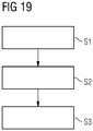
- a method for assembling the coupling arrangement comprises the steps of a) moving the nacelle and the tower towards each other, b) locking the nacelle to the tower in the direction opposite to the mounting direction by use of the locking means, and c) fastening nuts to the bolts.
- Fig. 1 shows a wind turbine 1 according to an embodiment.
- the wind turbine 1 comprises a rotor 2 connected to a generator (not shown) arranged inside a nacelle 8.
- the nacelle 8 is arranged at the upper end of a tower 6 of the wind turbine 1 and is preferably rotatable around a rotational axis of the tower 6.
- the rotor 2 comprises three blades 5, preferably with an adjustable pitch.
- the blades 5 are connected to a hub 3 of the wind turbine 1.
- Rotors 2 of this kind may have diameters ranging from, for example, 30 to 160 meters.
- the blades 5 are subjected to high wind loads. At the same time, the blades 5 need to be lightweight. For these reasons, blades 5 in modern wind turbines 1 are manufactured from fiber-reinforced composite materials.
- Fig. 2 shows, a process step during the assembly of the nacelle 8 to the tower 6 and thus the assembly of a coupling arrangement 7 according to an embodiment.
- the coupling arrangement 7 comprises a nacelle 8 and bolts 9 extending from the nacelle 8. Further, the coupling arrangement 7 comprises the tower 6 having a flange 10. Parallel bolt holes 11 extend through the flange 10. In addition to the bolts 9, the nacelle 8 has protruding elements 12 protruding further in a mounting direction M than the bolts 9. In the present example, the protruding elements 12 are formed as parallel protruding bolts.
- the coupling arrangement 7 further comprises locking means 13 shown in Fig. 3 .
- the locking means 13 comprise first elements 14 and second elements 15.
- the second element 15 comprises pins 16 biased by respective springs 17 in a direction perpendicular to the protruding bolt axis X and the mounting direction M.
- the pins 16 and associated springs 17 are arranged in recesses 18 of the second element 15.
- the first element 14 comprise stopping surfaces at the area with the reduced diameter 20 which are engaged by the pins 16 in their extended position when the protruding bolt 14 retracts in a direction opposite to the mounting direction M.
- the nacelle 8 is positioned relative to the tower 6 such that the bolts 9 and protruding bolts 12 are aligned with corresponding bolt holes 11, respectively.
- step S1 the nacelle 8 is moved towards the tower 6 in the mounting direction M.
- the protruding bolts 14 enter respective bolt holes 15 on the outer side of the flange 10.
- the pins 16, initially in their extended position are depressed.
- the area of the bolt 12, 14 with the reduced diameter 20 arrives at the position of the pins 16 and the pins snap into their extended position ( Fig. 3 ) due to the springs 17, i.e. without further human interaction (herein referred to as self-locking).
- the pins 16 together with the bolt 14 lock the nacelle 8 with respect to the tower 6 in a direction opposite the mounting direction M (step S2 in Fig. 19 ), i.e. the nacelle 8 cannot move further away from the tower 6 than the pins 16 and bolt 12, 14 allow.
- the bolts 9 enter their corresponding bolt holes 11 shortly after the protruding bolts 12, 14. This is a result of the protruding bolts 12 being longer than the bolts 9, for example by 1 to 20 cm.
- the protruding bolts 12 provide guidance for the bolts 9 to be threaded into their corresponding bolt holes 7.
- the bolts 9 preferably also extend past the inside surface of the flange 10, i.e. the bolts 9 extend through and past the bolt holes 11.
- Fig. 4 shows the protruding bolt or first element 12, 14 in a locked state.
- the protruding bolt 12 was received by the corresponding bolt hole.
- the pins 16 are pushed by the springs 17 from the recess 18 into the area with a reduced diameter 20 of the bolt 12.
- the bolt 12 is therefore locked in its position in the bolt hole by the pins 16.
- each of which comprising locking means 13 including at least one first element 14 and at least one second element 15 to be engaged with each other.
- Each of the depicted locking means 13 represents a way of locking protruding elements 12 of the nacelle 8 to the tower 6 in a direction opposite to the mounting direction M.
- Figs. 5 and 6 show a section view of a further embodiment of a coupling arrangement 7 similar to the embodiment of Fig. 3 .
- the protruding bolt 12 includes two rotatable arms 23 which are provided at the free end 19.
- the rotatable arms 23 are spring loaded by spring 17 in a direction perpendicular to the mounting direction M.
- the arms 23 are folded into the protruding bolt 12 (which usually occurs when the protruding bolt 12 enters the corresponding bolt hole 11).
- Fig. 6 the arms 23 are unfolded laterally and engaged with the stopping surfaces 15 at the flange 10 after the free end 19 of the protruding bolt 12 exits from the bolt hole 11.
- Fig. 7 shows a sectional view of a further embodiment of a coupling arrangement 7.
- the protruding bolt 12 has an extension 24 with a T-shaped cross-section.
- plate 26 is moved by an actuator 27, e.g. an electromagnet, in a direction N perpendicular to the mounting direction M such that a stopping surface 15 of the plate 26 bordering on a portion 28 having a reduced breadth of the keyhole 25 engages the extension 24.
- the plate 26 is supported such in the tower 6 or at the flange 10 that it can be moved in the direction N but is fixed in the direction opposite to the mounting direction M.
- the actuator 27 may be configured to be controlled by a user from remote, in particular from outside the tower 6.
- the actuator 27 may work fully automatically - to this end, the actuator 27 may comprise a sensor for sensing the presence of the protruding bolt 12. When sensing the protruding bolt 12, the actuator moves the plate 26 without any human intervention.
- Fig. 8 shows a further embodiment of a coupling arrangement 7.
- Fig. 8 shows a coupling arrangement 7.
- the protruding element 12 comprises a first element 14 and is arranged at the nacelle 8 within the ring of bolts 9 that are prepared to interact with the holes 11 in the flange 10.
- the first element 14 comprises a square shaped part
- the second element 15 comprises a square shaped opening.
- the square shaped opening of the second element 15 corresponds in size to the square shaped part of the first element 14, so that the square shaped element can be moved through the square shaped opening.
- the first element 14 protrudes longer from the nacelle 8 than the bolts 9. Thus the first element 14 can be locked with the second element 15, and thereafter the bolts 9 are introduced in the bolt holes 11 of the flange 10.
- either the first element 14 can be rotated in respect to the second element 15, or vice versa.
- Figs. 9 and 10 show section views of a further embodiment of a coupling arrangement 7.
- the protruding elements 12 are formed as lobes 30 respectively held rotatably about an axis G (the axis G being orientated parallel to the mounting direction M) at the nacelle 8.
- Protruding bolts 12 are not required in this example but may be provided.
- Figs. 11 and 12 The embodiment of Figs. 11 and 12 is similar to Figs. 9 and 10 .
- Hooks 31 are respectively provided rotatably about an axis Z perpendicular to the mounting direction M at the nacelle 8. Once the nacelle 8 has been moved towards the tower 6 in the mounting direction M to an extent where the bolts 9 have passed through corresponding bolt holes 11 (not shown), the hooks 31 are rotated about the axes Z and become engaged with stopping or engaging surfaces at the tower 6 or flange 10.
- Figs. 13 und 14 illustrate an embodiment of a coupling arrangement 7, wherein a protruding bolt 12 is provided with teeth 32 (first element) which become engaged with corresponding teeth 33 (second element) at the tower 6 or the flange 10 once the nacelle 8 has been moved towards the tower 6 in the mounting direction M to an extent where the bolts 9 have passed through corresponding bolt holes 11.
- Figs. 15 und 16 illustrate an embodiment of a coupling arrangement 7, wherein a protruding bolt 12 is provided with a threaded portion 34 (first element) which is engaged by a nut 35 (second element) provided at the tower 6 or at the flange 10 once the nacelle 8 has been moved towards the tower 6 in the mounting direction M to an extent where the bolts 9 have passed through corresponding bolt holes 11.
- the nut 35 may be rotated by an actuator (not shown) for engagement with the threaded portion 34.
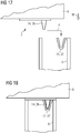
- the coupling arrangement 7 comprises a nacelle 8 having a V-shaped element 36 (first element) and a tower 6 having a corresponding V-shaped recess 37 (second element).
- the V-shaped element 36 is moved along path P to become engaged with the corresponding V-shaped recess 37 once the nacelle 8 has been moved towards the tower 6 in the mounting direction M to an extent where the bolts 9 have passed through corresponding bolt holes 11.
Landscapes
- Engineering & Computer Science (AREA)
- General Engineering & Computer Science (AREA)
- Mechanical Engineering (AREA)
- Life Sciences & Earth Sciences (AREA)
- Sustainable Development (AREA)
- Sustainable Energy (AREA)
- Chemical & Material Sciences (AREA)
- Combustion & Propulsion (AREA)
- Power Engineering (AREA)
- Wind Motors (AREA)
Claims (14)
- Agencement de couplage (7) dans le domaine des éoliennes comprenant- une nacelle (8) ayant une pluralité de premiers boulons (9),- un mât (6) ayant une pluralité de trous de boulon (11), les boulons (9) étant insérables dans les trous de boulon (11) en déplaçant la nacelle (8) et le mât (6) l'un vers l'autre dans une direction de montage (M), et- des moyens de verrouillage (13) destinés à verrouiller la nacelle (8) au mât (6) dans une direction opposée à la direction de montage (M),- dans lequel les moyens de verrouillage (13) comprennent un premier élément (14) et un second élément (15), dans lequel le premier élément (14) peut être mis en prise dans ou derrière le second élément (15) pour verrouiller la nacelle (8) au mât (6),- dans lequel la nacelle (8) comprend un élément en saillie (12) faisant saillie davantage dans la direction de montage que les premiers boulons (9), chacun des éléments en saillie (12) ayant l'un du premier ou du second élément (14, 15) des moyens de verrouillage (13) et le mât (6) ayant l'autre élément respectif du premier ou du second élément (14, 15) des moyens de verrouillage (13),- dans lequel les éléments en saillie (12) sont configurés en tant que seconds boulons en saillie insérables dans les trous (11) en déplaçant la nacelle (8) et le mât (6) l'un vers l'autre dans la direction de montage (M).
- Agencement de couplage (7) selon la revendication 1, dans lequel les moyens de verrouillage (13) sont configurés pour s'auto-verrouiller.
- Agencement de couplage (7) selon la revendication 2, dans lequel les moyens de verrouillage (13) sont actionnés par ressort (17) pour s'auto-verrouiller.
- Agencement de couplage (7) selon la revendication 1 ou 2, dans lequel les moyens de verrouillage (13) comprennent un actionneur (27), en particulier un actionneur électromagnétique ou hydraulique.
- Agencement de couplage (7) selon l'une des revendications 2 à 4, dans lequel le premier ou le second élément (14, 15) est actionné par ressort (17) dans une direction perpendiculaire à la direction de montage (M) pour se mettre en prise avec l'autre élément respectif du premier ou du second élément (14, 15).
- Agencement de couplage (7) selon l'une des revendications 4 et 5, dans lequel l'actionneur (27) actionne le premier ou le second élément (14, 15) dans une direction perpendiculaire à la direction de montage (M) pour se mettre en prise avec l'autre élément respectif du premier ou du second élément (14, 15).
- Agencement de couplage (7) selon l'une des revendications 2 à 6, dans lequel le premier élément (14) est configuré en tant qu'au moins une broche mobile (16), et le second élément (15) est configuré en tant que surface de butée pour se mettre en prise avec la broche mobile (16).
- Agencement de couplage (7) selon l'une des revendications 2 à 6, dans lequel le premier élément (14) est configuré en tant que bras rotatif (23) et le second élément (15) est configuré en tant que surface de butée destinée à se mettre en prise avec le bras rotatif (23).
- Agencement de couplage (7) selon l'une des revendications 2 à 6, dans lequel le premier élément (14) est un lobe rotatif (30) et le second élément est une surface de mise en prise correspondante.
- Agencement de couplage (7) selon l'une des revendications 2 à 6, dans lequel le premier élément (14) est un crochet rotatif (31) et le second élément est une surface correspondante qui peut être mise en prise par le crochet (31) ou dans lequel le premier élément (14) est un élément denté (32) et le second élément (15) est un élément denté (33) correspondant destiné à s'engrener avec l'élément denté (32).
- Agencement de couplage (7) selon l'une des revendications précédentes, dans lequel la nacelle comprend une première partie de moyens de guidage, et le mât comprend une seconde partie de moyens de guidage, moyennant quoi la première partie et la seconde partie des moyens de guidage sont préparées et agencées de façon à se mettre en butée l'une contre l'autre lorsque la nacelle est montée sur le mât, à limiter le mouvement de la nacelle par rapport au mât et à influencer la position de la nacelle par rapport au mât pour permettre au premier élément (14) et au second élément (15) de l'agencement de couplage d'interagir.
- Eolienne (1) comprenant l'agencement de couplage (7) selon l'une des revendications 1 à 11.
- Procédé destiné à assembler l'agencement de couplage (7) selon l'une des revendications 1 à 11, comprenant les étapes:- déplacer la nacelle (8) et le mât (6) l'un vers l'autre,- verrouiller la nacelle (8) sur le mât (6) dans la direction opposée à la direction de montage (M) au moyen de l'utilisation des moyens de verrouillage (13), et- fixer des écrous aux boulons (9).
- Procédé selon la revendication 13 destiné à assembler l'agencement de couplage (7) selon l'une des revendications 1 à 11, comprenant l'étape supplémentaire:- mettre en butée la première partie des moyens de guidage sur la seconde partie des moyens de guidage pour limiter le mouvement de la nacelle par rapport au mât et pour ajuster la position de la nacelle pour que les moyens de couplage interagissent.
Priority Applications (4)
| Application Number | Priority Date | Filing Date | Title |
|---|---|---|---|
| EP15169200.1A EP3098443B1 (fr) | 2015-05-26 | 2015-05-26 | Agencement de couplage dans un champ d'éoliennes |
| DK15169200T DK3098443T3 (da) | 2015-05-26 | 2015-05-26 | Koblingsanordning inden for området vindmøller |
| US15/148,047 US20160348650A1 (en) | 2015-05-26 | 2016-05-06 | Coupling arrangement in the field of wind turbines |
| CN201610355914.9A CN106194605B (zh) | 2015-05-26 | 2016-05-26 | 风力涡轮机领域的联接装置 |
Applications Claiming Priority (1)
| Application Number | Priority Date | Filing Date | Title |
|---|---|---|---|
| EP15169200.1A EP3098443B1 (fr) | 2015-05-26 | 2015-05-26 | Agencement de couplage dans un champ d'éoliennes |
Publications (2)
| Publication Number | Publication Date |
|---|---|
| EP3098443A1 EP3098443A1 (fr) | 2016-11-30 |
| EP3098443B1 true EP3098443B1 (fr) | 2019-07-31 |
Family
ID=53191613
Family Applications (1)
| Application Number | Title | Priority Date | Filing Date |
|---|---|---|---|
| EP15169200.1A Active EP3098443B1 (fr) | 2015-05-26 | 2015-05-26 | Agencement de couplage dans un champ d'éoliennes |
Country Status (4)
| Country | Link |
|---|---|
| US (1) | US20160348650A1 (fr) |
| EP (1) | EP3098443B1 (fr) |
| CN (1) | CN106194605B (fr) |
| DK (1) | DK3098443T3 (fr) |
Cited By (1)
| Publication number | Priority date | Publication date | Assignee | Title |
|---|---|---|---|---|
| CN112709672A (zh) * | 2020-12-23 | 2021-04-27 | 山东中车风电有限公司 | 一种分片式塔架段的密封防水结构及塔架 |
Families Citing this family (13)
| Publication number | Priority date | Publication date | Assignee | Title |
|---|---|---|---|---|
| US9783315B2 (en) * | 2012-02-24 | 2017-10-10 | Rohr, Inc. | Nacelle with longitudinal translating cowling and rotatable sleeves |
| EP2998569B1 (fr) * | 2014-09-22 | 2017-08-02 | Siemens Aktiengesellschaft | Dispositif pour aligner une partie d'une éolienne |
| DK3492734T3 (da) * | 2017-12-04 | 2020-08-10 | Siemens Gamesa Renewable Energy As | Vindmølle og fremgangsmåde til samling af en vindmølle |
| CN108506168A (zh) * | 2018-03-24 | 2018-09-07 | 于晓东 | 一种风力发电用多功能支撑架 |
| NL2021462B1 (en) * | 2018-08-13 | 2020-02-24 | Siemens Gamesa Renewable Energy B V | Assembly comprising a first and a second member and a connector, and a method of assembling such an assembly |
| EP3874162B1 (fr) * | 2018-11-02 | 2023-01-04 | Vestas Wind Systems A/S | Nacelle et procédé d'assemblage de celle-ci |
| CN109869279B (zh) * | 2019-03-29 | 2020-01-07 | 浙江海洋大学 | 一种海上风电机安装方法及安装系统 |
| EP3973178B1 (fr) | 2019-05-21 | 2024-04-24 | Vestas Wind Systems A/S | Procédé permettant d'ériger une tour d'éolienne à l'aide de boulons filetés |
| CN113279917B (zh) * | 2020-02-20 | 2023-03-03 | 江苏金风科技有限公司 | 塔筒段和风力发电机组 |
| CN112283052B (zh) * | 2020-11-12 | 2022-08-19 | 交口县棋盘山新能源有限公司 | 一种风力发电机的机头回转结构的定位装置 |
| CN114198261B (zh) * | 2021-12-24 | 2024-11-08 | 中交第一航务工程局有限公司 | 一种起重船浮态安装风机机舱的导向装置及操作方法 |
| EP4303430A1 (fr) * | 2022-07-04 | 2024-01-10 | Siemens Gamesa Renewable Energy A/S | Système d'assemblage d'éolienne et procédé d'assemblage d'éolienne |
| EP4722527A1 (fr) * | 2024-10-07 | 2026-04-08 | Siemens Gamesa Renewable Energy Innovation & Technology S.L. | Ensemble d'installation |
Family Cites Families (15)
| Publication number | Priority date | Publication date | Assignee | Title |
|---|---|---|---|---|
| US3613497A (en) * | 1969-04-10 | 1971-10-19 | U S Expansion Bolt Co | Expansion anchor |
| CA1331032C (fr) * | 1988-01-25 | 1994-07-26 | Thony, Franz | Appareil servant a raccorder deux pieces amovibles |
| CN2154376Y (zh) * | 1993-04-08 | 1994-01-26 | 庄清宝 | 枢接杆件结构 |
| JP2000283018A (ja) * | 1999-03-30 | 2000-10-10 | Fuji Heavy Ind Ltd | 水平軸風車及び該水平軸風車の建設方法 |
| JP4484143B2 (ja) * | 2004-06-09 | 2010-06-16 | 日東工器株式会社 | プラグ/ソケットアセンブリ |
| DE102005061824B4 (de) * | 2005-12-23 | 2007-10-31 | Fujitsu Siemens Computers Gmbh | Computergehäuse |
| DE202007011105U1 (de) * | 2007-08-09 | 2007-10-18 | Itw Automotive Products Gmbh & Co. Kg | Einteiliger Clip aus Kunststoff |
| CN201507522U (zh) * | 2009-07-30 | 2010-06-16 | 比亚迪股份有限公司 | 一种插销 |
| GB2484672B (en) * | 2010-10-18 | 2013-10-16 | Claxton Engineering Services Ltd | Tower connector |
| JP5106619B2 (ja) * | 2010-12-06 | 2012-12-26 | 株式会社日立製作所 | 風力発電装置及び風力発電装置のヨーベアリング交換方法 |
| CN201973070U (zh) * | 2010-12-30 | 2011-09-14 | 杭州奇尚商业展示系统有限公司 | 卡入式挂钩 |
| DK2538073T3 (en) * | 2011-06-24 | 2016-07-25 | Vestas Wind Sys As | An improvement of a horizontal wing installation of windmills |
| EP2696123A1 (fr) * | 2012-08-06 | 2014-02-12 | Siemens Aktiengesellschaft | Agencement de décrochage de câble |
| DK177908B1 (en) * | 2013-02-26 | 2014-12-15 | Envision Energy Denmark Aps | Tower assembly system for wind turbines and method thereof |
| CN204152907U (zh) * | 2014-09-23 | 2015-02-11 | 中国计量学院 | 一种杆的快速连接结构 |
-
2015
- 2015-05-26 EP EP15169200.1A patent/EP3098443B1/fr active Active
- 2015-05-26 DK DK15169200T patent/DK3098443T3/da active
-
2016
- 2016-05-06 US US15/148,047 patent/US20160348650A1/en not_active Abandoned
- 2016-05-26 CN CN201610355914.9A patent/CN106194605B/zh not_active Expired - Fee Related
Non-Patent Citations (1)
| Title |
|---|
| None * |
Cited By (1)
| Publication number | Priority date | Publication date | Assignee | Title |
|---|---|---|---|---|
| CN112709672A (zh) * | 2020-12-23 | 2021-04-27 | 山东中车风电有限公司 | 一种分片式塔架段的密封防水结构及塔架 |
Also Published As
| Publication number | Publication date |
|---|---|
| CN106194605B (zh) | 2020-12-08 |
| CN106194605A (zh) | 2016-12-07 |
| DK3098443T3 (da) | 2019-11-04 |
| US20160348650A1 (en) | 2016-12-01 |
| EP3098443A1 (fr) | 2016-11-30 |
Similar Documents
| Publication | Publication Date | Title |
|---|---|---|
| EP3098443A1 (fr) | Agencement de couplage dans un champ d'éoliennes | |
| EP2406490B1 (fr) | Verrou de rotor pour éolienne | |
| US8624412B2 (en) | Locking device for the rotor of wind turbines | |
| EP3040551B1 (fr) | Système de connection dans le domaine des éoliennes | |
| EP2406492B1 (fr) | Montage de pale | |
| US10054106B2 (en) | Counterweight systems for a wind turbine and methods | |
| EP2343454B1 (fr) | Dispositif de blockage de commande auxiliaire d'éolienne | |
| EP2525092B1 (fr) | Élément pour le levage de pale d'éolienne et procédé correspondant | |
| EP2527556B1 (fr) | Raccord à boulon destiné à une structure en treillis de tour éolienne | |
| US20140377062A1 (en) | Device and method for rotating a rotor of a wind turbine | |
| US20140073477A1 (en) | Fixture, maintenance assembly, and method for maintaining wind turbine gearbox | |
| EP2290228A2 (fr) | Dispositif de verrouillage d'un dispositif de commande de pas des pales | |
| EP3299615B1 (fr) | Système pour le montage/démontage de pales sur des aérogénérateurs | |
| US9909561B2 (en) | Rotor assembly for a wind turbine and method for mounting a blade to the rotor assembly | |
| US11181097B2 (en) | Multirotor wind turbine with guy wires | |
| EP3001030B1 (fr) | Installation des pales dans une éolienne et systèmes de levage de turbine éolienne | |
| US10641042B2 (en) | External ladder assembly for wind turbine nacelle | |
| EP3719310B1 (fr) | Dispositif de rotation de rotor pour une éolienne | |
| EP2837819B1 (fr) | Procédé pour installer une pale de rotor | |
| EP2607684B1 (fr) | Moyen de rotation du rotor d'une éolienne et procédé pour faire tourner le rotor | |
| EP4519559A1 (fr) | Système d'assemblage d'éolienne et procédé d'assemblage d'une éolienne | |
| US12497952B2 (en) | Couplings and auxiliary components for wind turbines, and associated methods | |
| WO2010128940A1 (fr) | Position de repos d'une éolienne | |
| WO2024037798A1 (fr) | Ensemble pour une boîte de vitesses pour une éolienne, agencement, kit, boîte de vitesses pour une éolienne, procédé de transport d'un ensemble pour une boîte de vitesses et procédé d'assemblage d'une éolienne |
Legal Events
| Date | Code | Title | Description |
|---|---|---|---|
| PUAI | Public reference made under article 153(3) epc to a published international application that has entered the european phase |
Free format text: ORIGINAL CODE: 0009012 |
|
| AK | Designated contracting states |
Kind code of ref document: A1 Designated state(s): AL AT BE BG CH CY CZ DE DK EE ES FI FR GB GR HR HU IE IS IT LI LT LU LV MC MK MT NL NO PL PT RO RS SE SI SK SM TR |
|
| AX | Request for extension of the european patent |
Extension state: BA ME |
|
| STAA | Information on the status of an ep patent application or granted ep patent |
Free format text: STATUS: REQUEST FOR EXAMINATION WAS MADE |
|
| 17P | Request for examination filed |
Effective date: 20170519 |
|
| RBV | Designated contracting states (corrected) |
Designated state(s): AL AT BE BG CH CY CZ DE DK EE ES FI FR GB GR HR HU IE IS IT LI LT LU LV MC MK MT NL NO PL PT RO RS SE SI SK SM TR |
|
| RAP1 | Party data changed (applicant data changed or rights of an application transferred) |
Owner name: SIEMENS AKTIENGESELLSCHAFT |
|
| REG | Reference to a national code |
Ref country code: DE Ref legal event code: R079 Ref document number: 602015034650 Country of ref document: DE Free format text: PREVIOUS MAIN CLASS: F03D0013200000 Ipc: F03D0001000000 |
|
| RIC1 | Information provided on ipc code assigned before grant |
Ipc: F03D 1/00 20060101AFI20190206BHEP |
|
| GRAP | Despatch of communication of intention to grant a patent |
Free format text: ORIGINAL CODE: EPIDOSNIGR1 |
|
| STAA | Information on the status of an ep patent application or granted ep patent |
Free format text: STATUS: GRANT OF PATENT IS INTENDED |
|
| INTG | Intention to grant announced |
Effective date: 20190319 |
|
| RAP1 | Party data changed (applicant data changed or rights of an application transferred) |
Owner name: SIEMENS GAMESA RENEWABLE ENERGY A/S |
|
| GRAS | Grant fee paid |
Free format text: ORIGINAL CODE: EPIDOSNIGR3 |
|
| GRAA | (expected) grant |
Free format text: ORIGINAL CODE: 0009210 |
|
| STAA | Information on the status of an ep patent application or granted ep patent |
Free format text: STATUS: THE PATENT HAS BEEN GRANTED |
|
| AK | Designated contracting states |
Kind code of ref document: B1 Designated state(s): AL AT BE BG CH CY CZ DE DK EE ES FI FR GB GR HR HU IE IS IT LI LT LU LV MC MK MT NL NO PL PT RO RS SE SI SK SM TR |
|
| REG | Reference to a national code |
Ref country code: CH Ref legal event code: EP Ref country code: GB Ref legal event code: FG4D |
|
| REG | Reference to a national code |
Ref country code: AT Ref legal event code: REF Ref document number: 1161171 Country of ref document: AT Kind code of ref document: T Effective date: 20190815 |
|
| REG | Reference to a national code |
Ref country code: IE Ref legal event code: FG4D |
|
| REG | Reference to a national code |
Ref country code: DE Ref legal event code: R096 Ref document number: 602015034650 Country of ref document: DE |
|
| REG | Reference to a national code |
Ref country code: DK Ref legal event code: T3 Effective date: 20191029 |
|
| REG | Reference to a national code |
Ref country code: NL Ref legal event code: MP Effective date: 20190731 |
|
| REG | Reference to a national code |
Ref country code: LT Ref legal event code: MG4D |
|
| REG | Reference to a national code |
Ref country code: AT Ref legal event code: MK05 Ref document number: 1161171 Country of ref document: AT Kind code of ref document: T Effective date: 20190731 |
|
| PG25 | Lapsed in a contracting state [announced via postgrant information from national office to epo] |
Ref country code: PT Free format text: LAPSE BECAUSE OF FAILURE TO SUBMIT A TRANSLATION OF THE DESCRIPTION OR TO PAY THE FEE WITHIN THE PRESCRIBED TIME-LIMIT Effective date: 20191202 Ref country code: LT Free format text: LAPSE BECAUSE OF FAILURE TO SUBMIT A TRANSLATION OF THE DESCRIPTION OR TO PAY THE FEE WITHIN THE PRESCRIBED TIME-LIMIT Effective date: 20190731 Ref country code: NL Free format text: LAPSE BECAUSE OF FAILURE TO SUBMIT A TRANSLATION OF THE DESCRIPTION OR TO PAY THE FEE WITHIN THE PRESCRIBED TIME-LIMIT Effective date: 20190731 Ref country code: HR Free format text: LAPSE BECAUSE OF FAILURE TO SUBMIT A TRANSLATION OF THE DESCRIPTION OR TO PAY THE FEE WITHIN THE PRESCRIBED TIME-LIMIT Effective date: 20190731 Ref country code: SE Free format text: LAPSE BECAUSE OF FAILURE TO SUBMIT A TRANSLATION OF THE DESCRIPTION OR TO PAY THE FEE WITHIN THE PRESCRIBED TIME-LIMIT Effective date: 20190731 Ref country code: BG Free format text: LAPSE BECAUSE OF FAILURE TO SUBMIT A TRANSLATION OF THE DESCRIPTION OR TO PAY THE FEE WITHIN THE PRESCRIBED TIME-LIMIT Effective date: 20191031 Ref country code: AT Free format text: LAPSE BECAUSE OF FAILURE TO SUBMIT A TRANSLATION OF THE DESCRIPTION OR TO PAY THE FEE WITHIN THE PRESCRIBED TIME-LIMIT Effective date: 20190731 Ref country code: NO Free format text: LAPSE BECAUSE OF FAILURE TO SUBMIT A TRANSLATION OF THE DESCRIPTION OR TO PAY THE FEE WITHIN THE PRESCRIBED TIME-LIMIT Effective date: 20191031 Ref country code: FI Free format text: LAPSE BECAUSE OF FAILURE TO SUBMIT A TRANSLATION OF THE DESCRIPTION OR TO PAY THE FEE WITHIN THE PRESCRIBED TIME-LIMIT Effective date: 20190731 |
|
| PG25 | Lapsed in a contracting state [announced via postgrant information from national office to epo] |
Ref country code: ES Free format text: LAPSE BECAUSE OF FAILURE TO SUBMIT A TRANSLATION OF THE DESCRIPTION OR TO PAY THE FEE WITHIN THE PRESCRIBED TIME-LIMIT Effective date: 20190731 Ref country code: RS Free format text: LAPSE BECAUSE OF FAILURE TO SUBMIT A TRANSLATION OF THE DESCRIPTION OR TO PAY THE FEE WITHIN THE PRESCRIBED TIME-LIMIT Effective date: 20190731 Ref country code: GR Free format text: LAPSE BECAUSE OF FAILURE TO SUBMIT A TRANSLATION OF THE DESCRIPTION OR TO PAY THE FEE WITHIN THE PRESCRIBED TIME-LIMIT Effective date: 20191101 Ref country code: AL Free format text: LAPSE BECAUSE OF FAILURE TO SUBMIT A TRANSLATION OF THE DESCRIPTION OR TO PAY THE FEE WITHIN THE PRESCRIBED TIME-LIMIT Effective date: 20190731 Ref country code: IS Free format text: LAPSE BECAUSE OF FAILURE TO SUBMIT A TRANSLATION OF THE DESCRIPTION OR TO PAY THE FEE WITHIN THE PRESCRIBED TIME-LIMIT Effective date: 20191130 Ref country code: LV Free format text: LAPSE BECAUSE OF FAILURE TO SUBMIT A TRANSLATION OF THE DESCRIPTION OR TO PAY THE FEE WITHIN THE PRESCRIBED TIME-LIMIT Effective date: 20190731 |
|
| PG25 | Lapsed in a contracting state [announced via postgrant information from national office to epo] |
Ref country code: TR Free format text: LAPSE BECAUSE OF FAILURE TO SUBMIT A TRANSLATION OF THE DESCRIPTION OR TO PAY THE FEE WITHIN THE PRESCRIBED TIME-LIMIT Effective date: 20190731 |
|
| PG25 | Lapsed in a contracting state [announced via postgrant information from national office to epo] |
Ref country code: RO Free format text: LAPSE BECAUSE OF FAILURE TO SUBMIT A TRANSLATION OF THE DESCRIPTION OR TO PAY THE FEE WITHIN THE PRESCRIBED TIME-LIMIT Effective date: 20190731 Ref country code: EE Free format text: LAPSE BECAUSE OF FAILURE TO SUBMIT A TRANSLATION OF THE DESCRIPTION OR TO PAY THE FEE WITHIN THE PRESCRIBED TIME-LIMIT Effective date: 20190731 Ref country code: IT Free format text: LAPSE BECAUSE OF FAILURE TO SUBMIT A TRANSLATION OF THE DESCRIPTION OR TO PAY THE FEE WITHIN THE PRESCRIBED TIME-LIMIT Effective date: 20190731 Ref country code: PL Free format text: LAPSE BECAUSE OF FAILURE TO SUBMIT A TRANSLATION OF THE DESCRIPTION OR TO PAY THE FEE WITHIN THE PRESCRIBED TIME-LIMIT Effective date: 20190731 |
|
| PG25 | Lapsed in a contracting state [announced via postgrant information from national office to epo] |
Ref country code: CZ Free format text: LAPSE BECAUSE OF FAILURE TO SUBMIT A TRANSLATION OF THE DESCRIPTION OR TO PAY THE FEE WITHIN THE PRESCRIBED TIME-LIMIT Effective date: 20190731 Ref country code: IS Free format text: LAPSE BECAUSE OF FAILURE TO SUBMIT A TRANSLATION OF THE DESCRIPTION OR TO PAY THE FEE WITHIN THE PRESCRIBED TIME-LIMIT Effective date: 20200224 Ref country code: SK Free format text: LAPSE BECAUSE OF FAILURE TO SUBMIT A TRANSLATION OF THE DESCRIPTION OR TO PAY THE FEE WITHIN THE PRESCRIBED TIME-LIMIT Effective date: 20190731 Ref country code: SM Free format text: LAPSE BECAUSE OF FAILURE TO SUBMIT A TRANSLATION OF THE DESCRIPTION OR TO PAY THE FEE WITHIN THE PRESCRIBED TIME-LIMIT Effective date: 20190731 |
|
| REG | Reference to a national code |
Ref country code: DE Ref legal event code: R097 Ref document number: 602015034650 Country of ref document: DE |
|
| PLBE | No opposition filed within time limit |
Free format text: ORIGINAL CODE: 0009261 |
|
| STAA | Information on the status of an ep patent application or granted ep patent |
Free format text: STATUS: NO OPPOSITION FILED WITHIN TIME LIMIT |
|
| PG2D | Information on lapse in contracting state deleted |
Ref country code: IS |
|
| PG25 | Lapsed in a contracting state [announced via postgrant information from national office to epo] |
Ref country code: IS Free format text: LAPSE BECAUSE OF FAILURE TO SUBMIT A TRANSLATION OF THE DESCRIPTION OR TO PAY THE FEE WITHIN THE PRESCRIBED TIME-LIMIT Effective date: 20191030 |
|
| 26N | No opposition filed |
Effective date: 20200603 |
|
| PG25 | Lapsed in a contracting state [announced via postgrant information from national office to epo] |
Ref country code: SI Free format text: LAPSE BECAUSE OF FAILURE TO SUBMIT A TRANSLATION OF THE DESCRIPTION OR TO PAY THE FEE WITHIN THE PRESCRIBED TIME-LIMIT Effective date: 20190731 |
|
| PG25 | Lapsed in a contracting state [announced via postgrant information from national office to epo] |
Ref country code: MC Free format text: LAPSE BECAUSE OF FAILURE TO SUBMIT A TRANSLATION OF THE DESCRIPTION OR TO PAY THE FEE WITHIN THE PRESCRIBED TIME-LIMIT Effective date: 20190731 Ref country code: LI Free format text: LAPSE BECAUSE OF NON-PAYMENT OF DUE FEES Effective date: 20200531 Ref country code: CH Free format text: LAPSE BECAUSE OF NON-PAYMENT OF DUE FEES Effective date: 20200531 |
|
| REG | Reference to a national code |
Ref country code: BE Ref legal event code: MM Effective date: 20200531 |
|
| PG25 | Lapsed in a contracting state [announced via postgrant information from national office to epo] |
Ref country code: LU Free format text: LAPSE BECAUSE OF NON-PAYMENT OF DUE FEES Effective date: 20200526 |
|
| PG25 | Lapsed in a contracting state [announced via postgrant information from national office to epo] |
Ref country code: IE Free format text: LAPSE BECAUSE OF NON-PAYMENT OF DUE FEES Effective date: 20200526 |
|
| PG25 | Lapsed in a contracting state [announced via postgrant information from national office to epo] |
Ref country code: BE Free format text: LAPSE BECAUSE OF NON-PAYMENT OF DUE FEES Effective date: 20200531 |
|
| PG25 | Lapsed in a contracting state [announced via postgrant information from national office to epo] |
Ref country code: MT Free format text: LAPSE BECAUSE OF FAILURE TO SUBMIT A TRANSLATION OF THE DESCRIPTION OR TO PAY THE FEE WITHIN THE PRESCRIBED TIME-LIMIT Effective date: 20190731 Ref country code: CY Free format text: LAPSE BECAUSE OF FAILURE TO SUBMIT A TRANSLATION OF THE DESCRIPTION OR TO PAY THE FEE WITHIN THE PRESCRIBED TIME-LIMIT Effective date: 20190731 |
|
| PG25 | Lapsed in a contracting state [announced via postgrant information from national office to epo] |
Ref country code: MK Free format text: LAPSE BECAUSE OF FAILURE TO SUBMIT A TRANSLATION OF THE DESCRIPTION OR TO PAY THE FEE WITHIN THE PRESCRIBED TIME-LIMIT Effective date: 20190731 |
|
| PGFP | Annual fee paid to national office [announced via postgrant information from national office to epo] |
Ref country code: GB Payment date: 20240522 Year of fee payment: 10 |
|
| PGFP | Annual fee paid to national office [announced via postgrant information from national office to epo] |
Ref country code: DE Payment date: 20240517 Year of fee payment: 10 |
|
| PGFP | Annual fee paid to national office [announced via postgrant information from national office to epo] |
Ref country code: DK Payment date: 20240522 Year of fee payment: 10 |
|
| PGFP | Annual fee paid to national office [announced via postgrant information from national office to epo] |
Ref country code: FR Payment date: 20240522 Year of fee payment: 10 |
|
| REG | Reference to a national code |
Ref country code: DE Ref legal event code: R119 Ref document number: 602015034650 Country of ref document: DE |
|
| REG | Reference to a national code |
Ref country code: DK Ref legal event code: EBP Effective date: 20250531 |
|
| GBPC | Gb: european patent ceased through non-payment of renewal fee |
Effective date: 20250526 |
|
| PG25 | Lapsed in a contracting state [announced via postgrant information from national office to epo] |
Ref country code: GB Free format text: LAPSE BECAUSE OF NON-PAYMENT OF DUE FEES Effective date: 20250526 |
|
| PG25 | Lapsed in a contracting state [announced via postgrant information from national office to epo] |
Ref country code: DK Free format text: LAPSE BECAUSE OF NON-PAYMENT OF DUE FEES Effective date: 20250531 Ref country code: DE Free format text: LAPSE BECAUSE OF NON-PAYMENT OF DUE FEES Effective date: 20251202 |
|
| PG25 | Lapsed in a contracting state [announced via postgrant information from national office to epo] |
Ref country code: FR Free format text: LAPSE BECAUSE OF NON-PAYMENT OF DUE FEES Effective date: 20250531 |