EP3098452B1 - Turbomachine - Google Patents
Turbomachine Download PDFInfo
- Publication number
- EP3098452B1 EP3098452B1 EP16160651.2A EP16160651A EP3098452B1 EP 3098452 B1 EP3098452 B1 EP 3098452B1 EP 16160651 A EP16160651 A EP 16160651A EP 3098452 B1 EP3098452 B1 EP 3098452B1
- Authority
- EP
- European Patent Office
- Prior art keywords
- shaft portion
- bearing surface
- bearing
- radial impeller
- connecting shaft
- Prior art date
- Legal status (The legal status is an assumption and is not a legal conclusion. Google has not performed a legal analysis and makes no representation as to the accuracy of the status listed.)
- Active
Links
Images
Classifications
-
- F—MECHANICAL ENGINEERING; LIGHTING; HEATING; WEAPONS; BLASTING
- F04—POSITIVE - DISPLACEMENT MACHINES FOR LIQUIDS; PUMPS FOR LIQUIDS OR ELASTIC FLUIDS
- F04D—NON-POSITIVE-DISPLACEMENT PUMPS
- F04D17/00—Radial-flow pumps, e.g. centrifugal pumps; Helico-centrifugal pumps
- F04D17/08—Centrifugal pumps
- F04D17/10—Centrifugal pumps for compressing or evacuating
- F04D17/12—Multi-stage pumps
-
- F—MECHANICAL ENGINEERING; LIGHTING; HEATING; WEAPONS; BLASTING
- F04—POSITIVE - DISPLACEMENT MACHINES FOR LIQUIDS; PUMPS FOR LIQUIDS OR ELASTIC FLUIDS
- F04D—NON-POSITIVE-DISPLACEMENT PUMPS
- F04D29/00—Details, component parts, or accessories
- F04D29/02—Selection of particular materials
- F04D29/023—Selection of particular materials especially adapted for elastic fluid pumps
-
- F—MECHANICAL ENGINEERING; LIGHTING; HEATING; WEAPONS; BLASTING
- F04—POSITIVE - DISPLACEMENT MACHINES FOR LIQUIDS; PUMPS FOR LIQUIDS OR ELASTIC FLUIDS
- F04D—NON-POSITIVE-DISPLACEMENT PUMPS
- F04D29/00—Details, component parts, or accessories
- F04D29/05—Shafts or bearings, or assemblies thereof, specially adapted for elastic fluid pumps
- F04D29/056—Bearings
-
- F—MECHANICAL ENGINEERING; LIGHTING; HEATING; WEAPONS; BLASTING
- F04—POSITIVE - DISPLACEMENT MACHINES FOR LIQUIDS; PUMPS FOR LIQUIDS OR ELASTIC FLUIDS
- F04D—NON-POSITIVE-DISPLACEMENT PUMPS
- F04D29/00—Details, component parts, or accessories
- F04D29/05—Shafts or bearings, or assemblies thereof, specially adapted for elastic fluid pumps
- F04D29/056—Bearings
- F04D29/0566—Ceramic bearing designs
-
- F—MECHANICAL ENGINEERING; LIGHTING; HEATING; WEAPONS; BLASTING
- F04—POSITIVE - DISPLACEMENT MACHINES FOR LIQUIDS; PUMPS FOR LIQUIDS OR ELASTIC FLUIDS
- F04D—NON-POSITIVE-DISPLACEMENT PUMPS
- F04D29/00—Details, component parts, or accessories
- F04D29/26—Rotors specially for elastic fluids
- F04D29/28—Rotors specially for elastic fluids for centrifugal or helico-centrifugal pumps for radial-flow or helico-centrifugal pumps
- F04D29/284—Rotors specially for elastic fluids for centrifugal or helico-centrifugal pumps for radial-flow or helico-centrifugal pumps for compressors
-
- F—MECHANICAL ENGINEERING; LIGHTING; HEATING; WEAPONS; BLASTING
- F16—ENGINEERING ELEMENTS AND UNITS; GENERAL MEASURES FOR PRODUCING AND MAINTAINING EFFECTIVE FUNCTIONING OF MACHINES OR INSTALLATIONS; THERMAL INSULATION IN GENERAL
- F16C—SHAFTS; FLEXIBLE SHAFTS; ELEMENTS OR CRANKSHAFT MECHANISMS; ROTARY BODIES OTHER THAN GEARING ELEMENTS; BEARINGS
- F16C17/00—Sliding-contact bearings for exclusively rotary movement
- F16C17/04—Sliding-contact bearings for exclusively rotary movement for axial load only
-
- F—MECHANICAL ENGINEERING; LIGHTING; HEATING; WEAPONS; BLASTING
- F16—ENGINEERING ELEMENTS AND UNITS; GENERAL MEASURES FOR PRODUCING AND MAINTAINING EFFECTIVE FUNCTIONING OF MACHINES OR INSTALLATIONS; THERMAL INSULATION IN GENERAL
- F16C—SHAFTS; FLEXIBLE SHAFTS; ELEMENTS OR CRANKSHAFT MECHANISMS; ROTARY BODIES OTHER THAN GEARING ELEMENTS; BEARINGS
- F16C17/00—Sliding-contact bearings for exclusively rotary movement
- F16C17/10—Sliding-contact bearings for exclusively rotary movement for both radial and axial load
- F16C17/102—Sliding-contact bearings for exclusively rotary movement for both radial and axial load with grooves in the bearing surface to generate hydrodynamic pressure
- F16C17/107—Sliding-contact bearings for exclusively rotary movement for both radial and axial load with grooves in the bearing surface to generate hydrodynamic pressure with at least one surface for radial load and at least one surface for axial load
-
- F—MECHANICAL ENGINEERING; LIGHTING; HEATING; WEAPONS; BLASTING
- F05—INDEXING SCHEMES RELATING TO ENGINES OR PUMPS IN VARIOUS SUBCLASSES OF CLASSES F01-F04
- F05D—INDEXING SCHEME FOR ASPECTS RELATING TO NON-POSITIVE-DISPLACEMENT MACHINES OR ENGINES, GAS-TURBINES OR JET-PROPULSION PLANTS
- F05D2220/00—Application
- F05D2220/40—Application in turbochargers
-
- F—MECHANICAL ENGINEERING; LIGHTING; HEATING; WEAPONS; BLASTING
- F05—INDEXING SCHEMES RELATING TO ENGINES OR PUMPS IN VARIOUS SUBCLASSES OF CLASSES F01-F04
- F05D—INDEXING SCHEME FOR ASPECTS RELATING TO NON-POSITIVE-DISPLACEMENT MACHINES OR ENGINES, GAS-TURBINES OR JET-PROPULSION PLANTS
- F05D2300/00—Materials; Properties thereof
- F05D2300/20—Oxide or non-oxide ceramics
-
- F—MECHANICAL ENGINEERING; LIGHTING; HEATING; WEAPONS; BLASTING
- F16—ENGINEERING ELEMENTS AND UNITS; GENERAL MEASURES FOR PRODUCING AND MAINTAINING EFFECTIVE FUNCTIONING OF MACHINES OR INSTALLATIONS; THERMAL INSULATION IN GENERAL
- F16C—SHAFTS; FLEXIBLE SHAFTS; ELEMENTS OR CRANKSHAFT MECHANISMS; ROTARY BODIES OTHER THAN GEARING ELEMENTS; BEARINGS
- F16C2360/00—Engines or pumps
- F16C2360/23—Gas turbine engines
- F16C2360/24—Turbochargers
Definitions
- the invention relates to a turbomachine according to claim 1.
- a turbomachine with a first and a second radial impeller is known.
- the radial impellers are rotatably mounted.
- an improved turbomachine can be provided by the turbomachine comprising at least a rotor and a stator, wherein the rotor is rotatably supported about an axis of rotation by means of a bearing device, wherein the rotor comprises a first radial impeller, wherein the first radial impeller the first blade assembly and a first and integrally formed with the first blade assembly first support assembly, wherein the bearing means comprises a first bearing shell having a first bearing surface, wherein the bearing means at the first Supporting arrangement comprises on a side facing away from the first blade assembly side, a second bearing surface, wherein between the first bearing surface and the second bearing surface, a first gap is provided, wherein the first bearing surface and the second bearing surface are in operative connection with one another via a fluid present in the first gap for mounting the rotor.
- the tolerances of the radial impeller in connection with the bearing device can be kept low, so that the turbomachine has a particularly high efficiency.
- the first bearing surface is arranged in a first plane of rotation to the axis of rotation, wherein the second bearing surface is arranged in a second plane of rotation to the axis of rotation, wherein the first gap is arranged axially between the first bearing surface and the second bearing surface and in the radial direction runs.
- the first radial impeller has a first shaft section.
- the first shaft section is arranged axially next to the first support arrangement on a side facing away from the first blade arrangement.
- the first bearing shell has a third bearing surface extending in the circumferential direction.
- the bearing device has on the first shaft portion circumferentially on a fourth bearing surface. Radial between the third bearing surface and the fourth bearing surface, a second gap extending in the axial direction is provided, wherein the second gap is preferably fluidly connected to the first gap.
- the first shaft section is formed in one piece and of the same material as the first support arrangement and the first blade arrangement.
- the third bearing surface is arranged axially adjacent to the first bearing surface.
- the first bearing surface extends substantially in the radial direction from the first shaft portion to a radially outer end of the first support assembly.
- the rotor comprises a second radial impeller.
- the second radial impeller is torque-coupled to the first radial impeller.
- the second radial impeller comprises a second blade arrangement and a second support arrangement formed integrally and integrally with the second blade arrangement.
- the second support arrangement is arranged on one of the first support arrangement facing side of the second radial impeller.
- the bearing device comprises a second bearing shell with a fifth bearing surface arranged in a third plane of rotation relative to the axis of rotation.
- the bearing device comprises a sixth bearing surface arranged on the second support arrangement, on a side facing the first support arrangement, in a fourth plane of rotation relative to the axis of rotation. Between the fifth bearing surface and the sixth bearing surface extending in the radial direction third gap is provided.
- the third gap is fluidically connected to the second gap.
- the turbomachine has a connection channel.
- the second radial impeller is connected upstream to a low pressure side and downstream to the connection channel.
- the first radial impeller is fluidically connected to the connection channel and downstream to a high pressure side.
- the second radial impeller is configured to deliver the fluid from the low pressure side into the communication passage and to raise a pressure of the fluid to a first pressure level.
- the first radial impeller is configured to deliver the fluid from the connection channel to the high pressure side and the fluid to a raise second pressure level.
- the gaps are configured to guide the portion of the fluid from the high pressure side to the first pressure level along the bearing surfaces. As a result, cooling of the bearing surfaces is achieved.
- the second radial impeller has a second shaft section.
- the second shaft portion is disposed axially adjacent to the second support assembly on a side facing the first radial impeller.
- the second shaft section is formed in one piece and of the same material as the second support arrangement and the second blade arrangement.
- the rotor has a connecting shaft.
- the connecting shaft is axially at least partially disposed between the first shaft portion and the second shaft portion and connects torque-locking the first shaft portion with the second shaft portion.
- first shaft section and / or the second shaft section has a receptacle and the connecting shaft has a connecting shaft section at at least one longitudinal end.
- the connecting shaft section engages the receptacle and couples the first and / or the second shaft section to the connecting shaft.
- the receptacle is arranged axially at the level of the fourth bearing surface.
- first bearing shell and the first radial impeller on an identical material. Additionally or alternatively, the first bearing shell and / or the first radial impeller one of the following materials: hard metal, ceramic.
- the bearing device is designed as a fluid bearing, in particular as a dynamic fluid bearing.
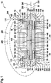
- FIG. 1 shows a semi-longitudinal section through a turbomachine 10th
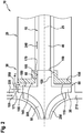
- FIG. 2 shows a section of the in FIG. 1 shown turbomachine 10.
- the turbomachine 10 is formed in the embodiment as a compressor for a heat pump cycle.
- the turbomachine 10 can also be embodied as a turbocompressor, turbocharger or as a microturbine or as a closed-cycle microturbine. It is also conceivable that the turbomachine 10 is mounted in a (block) cogeneration plant for power and / or heat generation.
- the turbomachine 10 has a rotor 15 and a stator 20.
- the rotor 15 is mounted rotatably about a rotation axis 25 by means of a bearing device 30 on the stator 20.
- the rotor 15 has a first radial impeller 35, a connecting shaft 40 and a second radial impeller 45.
- the first radial impeller 35 includes a first vane assembly 50, a first support assembly 55, and a first shaft portion 60.
- the first support assembly 55 is disposed axially adjacent the first vane assembly 50.
- the first support assembly 95 has a first radially outer end 171. Axially next to the first support assembly 55, on a side facing away from the first blade assembly 50 side, the first shaft portion 60 is arranged.
- the first blade assembly 50, the first support assembly 55 and the first shaft portion 60 are integrally formed of the same material. As a result, a particularly radially and mechanically stable first radial impeller 35 can be provided.
- the first radial impeller 35 has a first receptacle 65.
- the first shaft portion 60 is formed like a hollow shaft.
- the first receptacle 65 extends substantially axially over the entire axial width of the first shaft portion 60.
- the first recording 65 axially wider or narrower than in FIG. 1 is shown formed.
- the connecting shaft 40 has a first connecting shaft portion 70, a second connecting shaft portion 75, and a third connecting shaft portion 80.
- the first connection shaft portion 70 is disposed axially adjacent to the second connection shaft portion 75.
- the third connection shaft portion 80 is disposed axially adjacent to the second connection shaft portion 75 on a side of the second connection shaft portion 75 opposite to the first connection shaft portion 70.
- the first connecting shaft portion 70 is radially outwardly formed corresponding to the first receptacle 65 and engages in the first receptacle 65 and couples the connecting shaft 40 torque-locking with the first radial impeller 35.
- the coupling can be positive and / or cohesive.
- a diameter of the first shaft portion 60 is substantially identical to a diameter of the second connection shaft portion 70.
- the second radial impeller 45 is mirror-symmetrical to a plane of symmetry 85, which is aligned perpendicular to the axis of rotation 25 is formed.
- first radial impeller 35 and the second radial impeller 45 are formed asymmetrically to each other.
- the second radial impeller 45 has a second blade arrangement 90, a second support arrangement 95 and a second shaft section 100.
- the second shaft section 100 and the second support arrangement 95 are arranged on a side of the second radial impeller 45 facing the first support arrangement 55.
- the second support assembly 95 has a second radially outer end 245.
- the second blade arrangement 90 is arranged axially adjacent to the second support arrangement 95 on a side facing away from the first support arrangement 55.
- the second blade assembly 90, the second support assembly 95 and the second shaft portion 100 are integrally formed of the same material.
- the first radial impeller 35 and the second one Radial impeller 45 on the same material.
- the first radial impeller 35 has a different material to the second radial impeller 45.
- the second radial impeller 45 has a second receptacle 101.
- the second receptacle 101 is formed corresponding to the third connection shaft portion 80 of the connection shaft 40.
- the third connection shaft portion 80 engages in the second receptacle 101 and coupled torque-tight, the second radial impeller 45 with the connecting shaft 40.
- the coupling can be positive and / or cohesive.
- the bearing device 30 is designed as a fluid bearing, in particular as a gas-dynamic fluid bearing, and has a first bearing shell 105 and a second bearing shell 110.
- the bearing shells 105, 110 are formed like a bush.
- the first bearing shell 105 has a first radial section 115 and a first axial section 120.
- the second bearing shell 110 has a second radial section 125 and a second axial section 130.
- the first radial section 115 extends perpendicular to the axis of rotation 25 and adjoins the first axial section 120.
- the first radial section 115 is formed in the shape of a collar in relation to the first axial section 120.
- the bearing shells 105, 110 are mechanically supported by the stator 20.
- the stator 20 has radially on the outside of the bearing shells 105, 110 on an opposite side of the other bearing shell 105 an inner circumferential surface 111, 112 on.
- an inlet gap 151 is provided which has a width a 1 in the radial direction.
- an outlet gap 152 is provided which has a width a 2 in the radial direction.
- the second radial section 125 is arranged perpendicular to the axis of rotation 25 and adjoins the second axial section 130.
- the second radial portion is formed like a collar to the second axial portion 130.
- the first axial section 120 and the second axial section 130 are hollow-cylindrical.
- a drive motor 135 is provided.
- the drive motor 135 is formed in the embodiment as an electric machine.
- the drive motor 135 in this case has windings 140, which are arranged in the stator 20.
- the electric machine 135 has at least one permanent magnet 141.
- the permanent magnet 141 is connected in a torque-locking manner to the second connecting shaft section 75 of the connecting shaft 40.
- the first bearing shell 105 has a first bearing surface 145 on the first radial section 115.
- the first bearing surface 145 is arranged in a first plane of rotation, which is arranged perpendicular to the axis of rotation 25.
- the first bearing surface 145 extends substantially in the radial direction from the first shaft portion 60 to a radially outer end 171 of the first radial impeller 35.
- the first bearing surface 145 is narrower in the radial direction.
- the bearing device 30 on the first support arrangement 55 on a front side facing away from the first blade arrangement 50, has a second bearing surface 150 arranged in a second plane of rotation relative to the rotation axis 25. Between the first bearing surface 145 and the second bearing surface 150, a first gap 155 extending in the radial direction is provided. The first gap 155 is fluidically connected to the inlet gap 151.
- the first bearing shell 105 On an inner circumferential surface of the first axial section 120, the first bearing shell 105 has a third bearing surface 160 extending in the circumferential direction. Furthermore, the bearing device 30 comprises a fourth bearing surface 165 on the first shaft section 60 on an outer circumferential surface. Radially between the third bearing surface 160 and the fourth bearing surface 165, an axially extending second gap 170 is provided. The second gap 170 is fluidly connected to the first gap 155. In the embodiment, the third bearing surface 160 directly adjoins the first bearing surface 145. Of course, it is also conceivable that the third bearing surface 160 is arranged at a distance from the second bearing surface 150.
- the second bearing shell 110 has a fifth bearing surface 175 on the second radial section 125.
- the fifth bearing surface 175 is arranged in a third plane of rotation to the axis of rotation 25.
- the bearing device 30 has a sixth bearing surface 180 on the second support arrangement 95.
- the sixth bearing surface 180 is arranged in a fourth plane of rotation to the axis of rotation 25.
- a third gap 185 extending in the radial direction is provided between the fifth bearing surface 175 and the sixth bearing surface 180.
- the second axial section 130 has a seventh bearing surface 190 on an inner circumferential surface.
- the second shaft portion 100 has an eighth bearing surface 195 on an outer peripheral surface.
- the seventh bearing surface 190 and the eighth bearing surface 195 extend in the circumferential direction.
- a fourth gap 200 is provided between the seventh bearing surface 190 and the eighth bearing surface 195.
- the fourth gap 200 fluidly connects the second gap 170 fluidically with the third gap 185.
- the second and fourth gap 170, 200 are in this case designed as an annular gap, while the first and third gap 155, 185 are formed as a radial gap.
- another gap 201 may be provided, which is formed differently to the gaps 155, 170, 185, 200.
- the turbomachine 10 has a housing 205.
- the housing 205 has an inlet 210, an outlet 215 and in the embodiment by way of example a connection channel 220.
- the inlet 210 can be connected, for example, to a low-pressure side 225 of a heat pump cycle 230.
- the outlet 215 is fluidically connectable to a high pressure side 235 of the heat pump cycle 230.
- the heat pump cycle 230 has in the turbomachine an exemplary gaseous fluid 240 10 as a heat transfer medium.
- the fluid 240 may also be a gas-liquid mixture and / or a gas-solid mixture.
- the second radial impeller 45 is fluidly connected on the upstream side via the inlet 210 with the low pressure side 225. Downstream, the second radial impeller 45 is connected to the connection channel 220.
- the first radial impeller 35 is upstream with the connection channel 220 and downstream connected via the outlet 215 with the high pressure side 235 of the heat pump cycle 230
- the drive motor 135 rotates the rotor 15.
- the second radial impeller 45 sucks the gas 240 via the inlet 210 from the low-pressure side 225 and conveys it radially outward.
- the fluid 240 is compressed to a first pressure level.
- the fluid 240 flows downstream from the second radial impeller 45 into the connection channel 220.
- the fluid 240 is guided via the connection channel 220 from the second radial impeller 45 to the first radial impeller 35.
- the fluid 240 is supplied radially inward of the first blade arrangement 50.
- the first vane assembly 50 radially outwardly compresses the fluid 240 and compresses the fluid 240 from the first pressure level to a second pressure level. Radially outward, the fluid 240 flows from the second radial impeller 45 via the outlet 215 into the high pressure side 235 of the heat pump cycle 230.
- the fluid 240 also serves to support the rotor 15.
- the fluid 240 flows radially outward between the housing 205 and the radially outer end 171 of the first radial impeller 35 in the first gap 155 a.
- the fluid 240 flows radially from outside to inside in the first gap 155. From the first gap 155, the fluid 240 flows into the second gap 170.
- the configuration of the bearing device 30 as a fluid bearing forms the fluid 240 in the first and second gaps 155, 170, respectively Pad, so that the first bearing surface 145 axially spaced from the second bearing surface 150 and the third bearing surface 160 is radially spaced from the fourth bearing surface 165. As a result, a contact contact between the bearing surfaces 145, 150, 160, 165 is avoided.
- the fluid 240 flows along the second gap 170 and along a longitudinal direction of the connecting shaft 40.
- the fluid 240 flows from the second gap 170 into the further gap 201.
- the fluid 240 flows along the drive motor 135 and cools the windings 140 in particular Drive motor 135 flows the fluid 240 from the further gap 201 into the fourth gap 200.
- the fluid 240 forms another pad, so that the eighth bearing surface 195 is spaced apart from the seventh Storage area 190 rotates. As a result, wear between the second shaft portion 100 and the second bearing shell is avoided.
- the fluid 240 flows into the third gap 185 and flows radially from the inside to the outside.
- the fluid forms a further cushion between the fifth and sixth bearing surfaces 175, 180.
- the fluid 240 exits the third gap 185 via the outlet gap 152 downstream of the second radial impeller 45. Due to the difference in pressure between entry into the first gap 155 and exit from the third gap 185, the fluid 240 flows along the flow path just described across the gaps 155, 170, 185, 200, 201.
- the expansion of the fluid 240 from the second pressure level towards the fluid 240 cools both the bearing device 30 and the drive motor 135.
- the fluid 240 ensures a non-contact running of the radial impellers 35 through the formation of cushioning between the bearing surfaces 145, 150, 160, 165, 175, 180, 190, 195. 45, so that both an axial and a radial abutment of the bearing surfaces 145, 150, 160, 165, 175, 180, 190, 195 are avoided together.
- the above-described embodiment of the turbomachine 10 has the advantage that the rotor 15 can be mounted without contact on both sides of the bearing device 30 designed as a fluid bearing during operation of the turbomachine 10, so that tumbling of the rotor 15 can be avoided. Furthermore, a safe positioning of the rotor 15 is ensured by the fact that the bearing device 30 acts as a plain bearing in this state when starting and at a standstill of the turbomachine 10.
- the bearing shells 105, 110 may further be arranged axially far apart from each other, so that a reliable support of the rotor 15 is ensured.
- the arrangement of the first and second bearing shell 105, 110 in the stator 20, the stator 20 can be formed in one piece and of uniform material. Furthermore, inspection and service reliability for the turbomachine 10 is improved.
- the width a 1 and / or the width a 2 may be less than 50 ⁇ m, in particular less than 10 ⁇ m.
- an efficiency of the turbomachine 10 can be improved.
- the turbomachine 10 is particularly simple.
Landscapes
- Engineering & Computer Science (AREA)
- General Engineering & Computer Science (AREA)
- Mechanical Engineering (AREA)
- Physics & Mathematics (AREA)
- Fluid Mechanics (AREA)
- Chemical & Material Sciences (AREA)
- Ceramic Engineering (AREA)
- Structures Of Non-Positive Displacement Pumps (AREA)
Claims (11)
- Turbomachine (10), comprenant au moins un rotor (15) et un stator (20),- le rotor (15) étant monté rotatif autour d'un axe de rotation (25) au moyen d'un dispositif formant palier (30),- le rotor (15) comportant une première roue mobile radiale (35),- la première roue mobile radiale (35) comportant un premier arrangement d'aubes (50) et un premier arrangement d'appui (55) réalisé d'un seul tenant avec le premier arrangement d'aubes (50) et dans la même matière que celui-ci,- le dispositif formant palier (30) comportant une première coque de palier (105) dotée d'une première surface d'appui (145),- le dispositif formant palier (30) comportant une deuxième surface d'appui (150) au niveau du premier arrangement d'appui (55), sur un côté à l'opposé du premier arrangement d'aubes (50),- un premier interstice (155) se trouvant entre la première surface d'appui (145) et la deuxième surface d'appui (150),- la première surface d'appui (145) et la deuxième surface d'appui (150) se trouvant en liaison active l'une avec l'autre en vue de supporter le rotor (15) par le biais d'un fluide (240) présent dans le premier interstice (155),- la première roue mobile radiale (35) possédant une première portion d'arbre (60),- la première portion d'arbre (60) étant disposée dans le sens axial à côté du premier arrangement d'appui (55) sur un côté à l'opposé du premier arrangement d'aubes (50),- la première roue mobile radiale (35) possédant un premier logement (65) dans la première portion d'arbre (60), la première portion d'arbre (60) étant configurée en arbre creux dans la zone du premier logement (65) et le premier logement (65) s'étendant sensiblement dans le sens axial sur toute la largeur axiale de la première portion d'arbre (60),- la première coque de palier (105) comportant une troisième surface d'appui (160) qui s'étend dans la direction périphérique,- le dispositif formant palier (30) comportant une quatrième surface d'appui (165) sur le côté périphérique au niveau de la première portion d'arbre (60),- un deuxième interstice (170) qui s'étend dans la direction axiale se trouvant dans le sens radial entre la troisième surface d'appui (160) et la quatrième surface d'appui (165),- le deuxième interstice (170) étant de préférence en liaison fluidique avec le premier interstice (155),- le rotor (15) possédant un arbre de liaison (40),- l'arbre de liaison (40) possédant une première portion d'arbre de liaison (70), une deuxième portion d'arbre de liaison (75) et une troisième portion d'arbre de liaison (80),- la première portion d'arbre de liaison (70) étant disposée au niveau d'une extrémité longitudinale de l'arbre de liaison (40) et de manière axialement adjacente à la deuxième portion d'arbre de liaison (75),- la troisième portion d'arbre de liaison (80) étant disposée de manière axialement adjacente à la deuxième portion d'arbre de liaison (75) sur un côté de la deuxième portion d'arbre de liaison (75) opposé à la première portion d'arbre de liaison (70),caractérisée en ce que- la première portion d'arbre (60) est réalisée d'un seul tenant avec le premier arrangement d'appui (55) et le premier arrangement d'aubes (50) et dans la même manière que ceux-ci,- la première portion d'arbre de liaison (70) étant configurée, du côté extérieur dans le sens radial, en correspondance avec le premier logement (65) et venant en prise dans le premier logement (65) et accouplant l'arbre de liaison (40) à la première roue mobile radiale (35) en transmission de couple,- un diamètre extérieur de la première portion d'arbre (60) étant sensiblement identique à un diamètre extérieur de la deuxième portion d'arbre de liaison (70).
- Turbomachine (10) selon la revendication 1,- la première surface d'appui (145) étant disposée dans un premier plan de rotation par rapport à l'axe de rotation (25),- la deuxième surface d'appui (150) étant disposée dans un deuxième plan de rotation par rapport à l'axe de rotation (25),- le premier interstice (155) étant disposé axialement entre la première surface d'appui (145) et la deuxième surface d'appui (150) et s'étendant dans la direction radiale.
- Turbomachine (10) selon la revendication 1 ou 2, la troisième surface d'appui (160) étant disposée adjacente à la première surface d'appui (145).
- Turbomachine (10) selon l'une des revendications 1 à 3, la première surface d'appui (145) se projetant sensiblement dans la direction radiale de la première portion d'arbre (60) jusqu'à une extrémité (171), située à l'extérieur dans le sens radial, du premier arrangement d'appui (55).
- Turbomachine (10) selon l'une des revendications 1 à 4,- le rotor (15) comportant une deuxième roue mobile radiale (45),- la deuxième roue mobile radiale (45) étant accouplée avec la première roue mobile radiale (35) en transmission de couple,- la deuxième roue mobile radiale (45) comportant un deuxième arrangement d'aubes (90) et un deuxième arrangement d'appui (95), réalisé d'un seul tenant avec le deuxième arrangement d'aubes (90) et dans la même matière que celui-ci,- le deuxième arrangement d'appui (95) étant disposé sur un côté de la deuxième roue mobile radiale (45) faisant face au premier arrangement d'appui (55),- le dispositif formant palier (30) comportant une deuxième coque de palier (110) dotée d'une cinquième surface d'appui (175) disposée dans un troisième plan de rotation par rapport à l'axe de rotation (25),- le dispositif formant palier (30) comportant une sixième surface d'appui (180) disposée au niveau du deuxième arrangement d'appui (95) sur un côté faisant face au premier arrangement d'appui (55) dans un quatrième plan de rotation par rapport à l'axe de rotation (25),- un troisième interstice (185) qui s'étend dans la direction radiale se trouvant entre la cinquième surface d'appui (175) et la sixième surface d'appui (180).
- Turbomachine (10) selon la revendication 5, le troisième interstice (185) étant en liaison fluidique avec le deuxième interstice (170).
- Turbomachine (10) selon la revendication 5 ou 6,- possédant un canal de liaison (220),- la deuxième roue mobile radiale (45) étant reliée côté amont à un côté basse pression (225) et côté aval au canal de liaison (220),- la première roue mobile radiale (35) étant reliée côté amont au canal de liaison (220) et étant reliée fluidiquement côté aval à un côté haute pression (235),- la deuxième roue mobile radiale (45) étant configurée pour transporter le fluide (240) du côté basse pression (225) dans le canal de liaison (220) et élever une pression du fluide (240) à un premier niveau de pression,- la première roue mobile radiale (35) étant configurée pour transporter le fluide (240) du canal de liaison (220) au côté haute pression (235) et élever le fluide (240) à un deuxième niveau de pression,- les interstices (155, 170, 185, 200) étant configurés pour guider la partie du fluide (240) depuis le côté haute pression (235) vers le premier niveau de pression le long des surfaces d'appui (145, 150, 160, 165, 175, 180, 190, 195) .
- Turbomachine (10) selon l'une des revendications 5 à 7,- la deuxième roue mobile radiale (45) possédant une deuxième portion d'arbre (100),- la deuxième portion d'arbre (100) étant disposée dans le sens axial à côté du deuxième arrangement d'appui (95) sur un côté faisant face à la première roue mobile radiale (35),- la deuxième portion d'arbre (100) étant réalisée d'un seul tenant avec le deuxième arrangement d'appui (95) et le deuxième arrangement d'aubes (90) et dans la même matière que ceux-ci,- le rotor (15) comportant un arbre de liaison (40),- l'arbre de liaison (40) étant disposé dans le sens axial au moins partiellement entre la première portion d'arbre (60) et la deuxième portion d'arbre (100) et reliant la première portion d'arbre (60) à la deuxième portion d'arbre (100) en transmission de couple.
- Turbomachine (10) selon la revendication 8,- la deuxième portion d'arbre (100) possédant un logement supplémentaire (101) et l'arbre de liaison (40) la troisième portion d'arbre de liaison (80) au niveau d'au moins une extrémité longitudinale,- la troisième portion d'arbre de liaison (80) venant en prise dans le logement supplémentaire (101) et accouplant la deuxième portion d'arbre (100) à l'arbre de liaison (40),- le logement (65, 101) étant de préférence disposé au moins partiellement dans le sens axial à la hauteur de la quatrième surface d'appui (165).
- Turbomachine (10) selon la revendication 9,- la première coque de palier (105) et la première roue mobile radiale (35) présentant un matériau identique- et/ou- la première coque de palier (105) et/ou la première roue mobile radiale (35) présentant l'un des matériaux suivants : métal dur, céramique.
- Turbomachine (10) selon l'une des revendications 1 à 10, le dispositif formant palier (30) étant réalisé sous la forme d'un palier à fluide, notamment sous la forme d'un palier à fluide dynamique.
Applications Claiming Priority (1)
| Application Number | Priority Date | Filing Date | Title |
|---|---|---|---|
| DE102015209682.3A DE102015209682A1 (de) | 2015-05-27 | 2015-05-27 | Turbomaschine |
Publications (2)
| Publication Number | Publication Date |
|---|---|
| EP3098452A1 EP3098452A1 (fr) | 2016-11-30 |
| EP3098452B1 true EP3098452B1 (fr) | 2019-10-16 |
Family
ID=55650127
Family Applications (1)
| Application Number | Title | Priority Date | Filing Date |
|---|---|---|---|
| EP16160651.2A Active EP3098452B1 (fr) | 2015-05-27 | 2016-03-16 | Turbomachine |
Country Status (2)
| Country | Link |
|---|---|
| EP (1) | EP3098452B1 (fr) |
| DE (1) | DE102015209682A1 (fr) |
Families Citing this family (4)
| Publication number | Priority date | Publication date | Assignee | Title |
|---|---|---|---|---|
| KR101970400B1 (ko) * | 2016-08-12 | 2019-08-13 | 한양대학교 에리카산학협력단 | 공기 베어링 및 회전체 시스템 |
| DE102020202130A1 (de) * | 2020-02-19 | 2021-08-19 | Robert Bosch Gesellschaft mit beschränkter Haftung | Gaszuführvorrichtung |
| CN115263800B (zh) * | 2022-06-06 | 2025-02-25 | 中国船舶重工集团公司第七一九研究所 | 用于管道泵叶轮的支承装置及管道泵 |
| CN117006068A (zh) * | 2023-08-22 | 2023-11-07 | 珠海格力电器股份有限公司 | 压缩机及空调器 |
Family Cites Families (10)
| Publication number | Priority date | Publication date | Assignee | Title |
|---|---|---|---|---|
| GB1249863A (en) * | 1968-01-22 | 1971-10-13 | Lucas Industries Ltd | Gas bearings |
| DE3143606A1 (de) * | 1981-11-03 | 1983-05-11 | MTU Motoren- und Turbinen-Union München GmbH, 8000 München | "gaslagerung relativ zueinander sich bewegender bauteile" |
| DE69114139T2 (de) * | 1991-12-19 | 1996-04-04 | United Technologies Corp | Kühlung für Lager einer Luftkreisanlage. |
| US6231302B1 (en) * | 1999-06-08 | 2001-05-15 | G. Fonda Bonardi | Thermal control system for gas-bearing turbocompressors |
| EP1205678A1 (fr) * | 2000-11-07 | 2002-05-15 | Ingersoll-Rand Company | Palier à gaz |
| US7948105B2 (en) * | 2007-02-01 | 2011-05-24 | R&D Dynamics Corporation | Turboalternator with hydrodynamic bearings |
| US7758320B2 (en) * | 2007-05-03 | 2010-07-20 | Tank, Inc. | Two-stage hydrodynamic pump and method |
| DE102008014684A1 (de) * | 2008-03-18 | 2009-10-15 | Continental Automotive Gmbh | Turbolader mit einer Lageranordnung zur Lagerung einer Welle des Turboladers |
| DE102008059598A1 (de) * | 2008-11-28 | 2010-06-02 | Bosch Mahle Turbo Systems Gmbh & Co. Kg | Abgasturbolader |
| DE102011001530A1 (de) | 2011-03-24 | 2012-09-27 | Atlas Copco Energas Gmbh | Turbomaschine |
-
2015
- 2015-05-27 DE DE102015209682.3A patent/DE102015209682A1/de not_active Withdrawn
-
2016
- 2016-03-16 EP EP16160651.2A patent/EP3098452B1/fr active Active
Non-Patent Citations (1)
| Title |
|---|
| None * |
Also Published As
| Publication number | Publication date |
|---|---|
| DE102015209682A1 (de) | 2016-12-01 |
| EP3098452A1 (fr) | 2016-11-30 |
Similar Documents
| Publication | Publication Date | Title |
|---|---|---|
| EP3098452B1 (fr) | Turbomachine | |
| EP1898054B1 (fr) | Turbine a gaz | |
| DE102017115042A1 (de) | Deckbandkonfigurationen für Turbinenlaufschaufeln | |
| EP3040560B1 (fr) | Dispositif de boitier pour un etage d'un compresseur a plusieurs etages et procede de fabrication d'un dispositif de boitier | |
| DE102011051650A1 (de) | Axiale Wellenabdichtung | |
| CH713305B1 (de) | Turbolader. | |
| EP1148209B1 (fr) | Configuration de joint inter-étages | |
| DE102008017844A1 (de) | Strömungsmaschine mit Fluid-Injektorbaugruppe | |
| DE102008032661A1 (de) | Strömungsmaschine | |
| EP3039298A1 (fr) | Rotor de compresseur radial muni d'un bandage et d'un palier aérodynamique entre le bandage et le carter | |
| EP2884054A1 (fr) | Aube de guidage variable avec cône tronqué dans un ensemble palier | |
| DE102007050916A1 (de) | Verfahren und Vorrichtung zum Zusammenbau von Gasturbinen-Triebwerken | |
| WO2016184550A1 (fr) | Compresseur centrifuge et turbocompresseur à gaz d'échappement d'un moteur à combustion interne | |
| EP1624192A1 (fr) | Aube de rouet pour compresseur axial | |
| EP2871325B1 (fr) | Virole interne d'une turbomachine et distributeur | |
| DE102008057729A1 (de) | Abgasturbolader | |
| EP2284426B1 (fr) | Turbomachine | |
| CH708842A2 (de) | Leitschaufelanordnung zur Sicherung von Turbinenleitschaufeln innerhalb einer Nut eines Aussenrings. | |
| DE102017118795B4 (de) | Verstellbarer Leitapparat für eine Turbine, Turbine für einen Abgasturbolader und Abgasturbolader | |
| EP1507959B1 (fr) | Ensemble pour la fixation axiale et radiale des aubes fixes d'un stator d'une turbine a gaz | |
| EP0690204A2 (fr) | Turbine à vapeur ayant au moins deux joint pour assurer l'étanchéité du carter | |
| DE102015220131A1 (de) | Verdichtereinrichtung, Antriebsvorrichtung, Kraftfahrzeug | |
| DE102016112520A1 (de) | Lagervorrichtung für einen Abgasturbolader und Abgasturbolader | |
| EP2572108B1 (fr) | Compresseur centrifuge | |
| EP2235377B1 (fr) | Pompe turbomoléculaire |
Legal Events
| Date | Code | Title | Description |
|---|---|---|---|
| PUAI | Public reference made under article 153(3) epc to a published international application that has entered the european phase |
Free format text: ORIGINAL CODE: 0009012 |
|
| AK | Designated contracting states |
Kind code of ref document: A1 Designated state(s): AL AT BE BG CH CY CZ DE DK EE ES FI FR GB GR HR HU IE IS IT LI LT LU LV MC MK MT NL NO PL PT RO RS SE SI SK SM TR |
|
| AX | Request for extension of the european patent |
Extension state: BA ME |
|
| STAA | Information on the status of an ep patent application or granted ep patent |
Free format text: STATUS: REQUEST FOR EXAMINATION WAS MADE |
|
| 17P | Request for examination filed |
Effective date: 20170530 |
|
| RBV | Designated contracting states (corrected) |
Designated state(s): AL AT BE BG CH CY CZ DE DK EE ES FI FR GB GR HR HU IE IS IT LI LT LU LV MC MK MT NL NO PL PT RO RS SE SI SK SM TR |
|
| GRAP | Despatch of communication of intention to grant a patent |
Free format text: ORIGINAL CODE: EPIDOSNIGR1 |
|
| STAA | Information on the status of an ep patent application or granted ep patent |
Free format text: STATUS: GRANT OF PATENT IS INTENDED |
|
| INTG | Intention to grant announced |
Effective date: 20190513 |
|
| GRAS | Grant fee paid |
Free format text: ORIGINAL CODE: EPIDOSNIGR3 |
|
| GRAA | (expected) grant |
Free format text: ORIGINAL CODE: 0009210 |
|
| STAA | Information on the status of an ep patent application or granted ep patent |
Free format text: STATUS: THE PATENT HAS BEEN GRANTED |
|
| AK | Designated contracting states |
Kind code of ref document: B1 Designated state(s): AL AT BE BG CH CY CZ DE DK EE ES FI FR GB GR HR HU IE IS IT LI LT LU LV MC MK MT NL NO PL PT RO RS SE SI SK SM TR |
|
| REG | Reference to a national code |
Ref country code: GB Ref legal event code: FG4D Free format text: NOT ENGLISH |
|
| REG | Reference to a national code |
Ref country code: DE Ref legal event code: R096 Ref document number: 502016007082 Country of ref document: DE Ref country code: CH Ref legal event code: EP |
|
| REG | Reference to a national code |
Ref country code: IE Ref legal event code: FG4D Free format text: LANGUAGE OF EP DOCUMENT: GERMAN |
|
| REG | Reference to a national code |
Ref country code: AT Ref legal event code: REF Ref document number: 1191539 Country of ref document: AT Kind code of ref document: T Effective date: 20191115 |
|
| REG | Reference to a national code |
Ref country code: NL Ref legal event code: MP Effective date: 20191016 |
|
| REG | Reference to a national code |
Ref country code: LT Ref legal event code: MG4D |
|
| RAP2 | Party data changed (patent owner data changed or rights of a patent transferred) |
Owner name: ROBERT BOSCH GMBH |
|
| PG25 | Lapsed in a contracting state [announced via postgrant information from national office to epo] |
Ref country code: NL Free format text: LAPSE BECAUSE OF FAILURE TO SUBMIT A TRANSLATION OF THE DESCRIPTION OR TO PAY THE FEE WITHIN THE PRESCRIBED TIME-LIMIT Effective date: 20191016 Ref country code: SE Free format text: LAPSE BECAUSE OF FAILURE TO SUBMIT A TRANSLATION OF THE DESCRIPTION OR TO PAY THE FEE WITHIN THE PRESCRIBED TIME-LIMIT Effective date: 20191016 Ref country code: LV Free format text: LAPSE BECAUSE OF FAILURE TO SUBMIT A TRANSLATION OF THE DESCRIPTION OR TO PAY THE FEE WITHIN THE PRESCRIBED TIME-LIMIT Effective date: 20191016 Ref country code: PT Free format text: LAPSE BECAUSE OF FAILURE TO SUBMIT A TRANSLATION OF THE DESCRIPTION OR TO PAY THE FEE WITHIN THE PRESCRIBED TIME-LIMIT Effective date: 20200217 Ref country code: BG Free format text: LAPSE BECAUSE OF FAILURE TO SUBMIT A TRANSLATION OF THE DESCRIPTION OR TO PAY THE FEE WITHIN THE PRESCRIBED TIME-LIMIT Effective date: 20200116 Ref country code: FI Free format text: LAPSE BECAUSE OF FAILURE TO SUBMIT A TRANSLATION OF THE DESCRIPTION OR TO PAY THE FEE WITHIN THE PRESCRIBED TIME-LIMIT Effective date: 20191016 Ref country code: LT Free format text: LAPSE BECAUSE OF FAILURE TO SUBMIT A TRANSLATION OF THE DESCRIPTION OR TO PAY THE FEE WITHIN THE PRESCRIBED TIME-LIMIT Effective date: 20191016 Ref country code: PL Free format text: LAPSE BECAUSE OF FAILURE TO SUBMIT A TRANSLATION OF THE DESCRIPTION OR TO PAY THE FEE WITHIN THE PRESCRIBED TIME-LIMIT Effective date: 20191016 Ref country code: NO Free format text: LAPSE BECAUSE OF FAILURE TO SUBMIT A TRANSLATION OF THE DESCRIPTION OR TO PAY THE FEE WITHIN THE PRESCRIBED TIME-LIMIT Effective date: 20200116 Ref country code: GR Free format text: LAPSE BECAUSE OF FAILURE TO SUBMIT A TRANSLATION OF THE DESCRIPTION OR TO PAY THE FEE WITHIN THE PRESCRIBED TIME-LIMIT Effective date: 20200117 |
|
| PG25 | Lapsed in a contracting state [announced via postgrant information from national office to epo] |
Ref country code: RS Free format text: LAPSE BECAUSE OF FAILURE TO SUBMIT A TRANSLATION OF THE DESCRIPTION OR TO PAY THE FEE WITHIN THE PRESCRIBED TIME-LIMIT Effective date: 20191016 Ref country code: HR Free format text: LAPSE BECAUSE OF FAILURE TO SUBMIT A TRANSLATION OF THE DESCRIPTION OR TO PAY THE FEE WITHIN THE PRESCRIBED TIME-LIMIT Effective date: 20191016 Ref country code: IS Free format text: LAPSE BECAUSE OF FAILURE TO SUBMIT A TRANSLATION OF THE DESCRIPTION OR TO PAY THE FEE WITHIN THE PRESCRIBED TIME-LIMIT Effective date: 20200224 |
|
| PG25 | Lapsed in a contracting state [announced via postgrant information from national office to epo] |
Ref country code: AL Free format text: LAPSE BECAUSE OF FAILURE TO SUBMIT A TRANSLATION OF THE DESCRIPTION OR TO PAY THE FEE WITHIN THE PRESCRIBED TIME-LIMIT Effective date: 20191016 |
|
| REG | Reference to a national code |
Ref country code: DE Ref legal event code: R097 Ref document number: 502016007082 Country of ref document: DE |
|
| PG2D | Information on lapse in contracting state deleted |
Ref country code: IS |
|
| PG25 | Lapsed in a contracting state [announced via postgrant information from national office to epo] |
Ref country code: RO Free format text: LAPSE BECAUSE OF FAILURE TO SUBMIT A TRANSLATION OF THE DESCRIPTION OR TO PAY THE FEE WITHIN THE PRESCRIBED TIME-LIMIT Effective date: 20191016 Ref country code: CZ Free format text: LAPSE BECAUSE OF FAILURE TO SUBMIT A TRANSLATION OF THE DESCRIPTION OR TO PAY THE FEE WITHIN THE PRESCRIBED TIME-LIMIT Effective date: 20191016 Ref country code: ES Free format text: LAPSE BECAUSE OF FAILURE TO SUBMIT A TRANSLATION OF THE DESCRIPTION OR TO PAY THE FEE WITHIN THE PRESCRIBED TIME-LIMIT Effective date: 20191016 Ref country code: DK Free format text: LAPSE BECAUSE OF FAILURE TO SUBMIT A TRANSLATION OF THE DESCRIPTION OR TO PAY THE FEE WITHIN THE PRESCRIBED TIME-LIMIT Effective date: 20191016 Ref country code: EE Free format text: LAPSE BECAUSE OF FAILURE TO SUBMIT A TRANSLATION OF THE DESCRIPTION OR TO PAY THE FEE WITHIN THE PRESCRIBED TIME-LIMIT Effective date: 20191016 Ref country code: IS Free format text: LAPSE BECAUSE OF FAILURE TO SUBMIT A TRANSLATION OF THE DESCRIPTION OR TO PAY THE FEE WITHIN THE PRESCRIBED TIME-LIMIT Effective date: 20200216 |
|
| PLBE | No opposition filed within time limit |
Free format text: ORIGINAL CODE: 0009261 |
|
| STAA | Information on the status of an ep patent application or granted ep patent |
Free format text: STATUS: NO OPPOSITION FILED WITHIN TIME LIMIT |
|
| PG25 | Lapsed in a contracting state [announced via postgrant information from national office to epo] |
Ref country code: SK Free format text: LAPSE BECAUSE OF FAILURE TO SUBMIT A TRANSLATION OF THE DESCRIPTION OR TO PAY THE FEE WITHIN THE PRESCRIBED TIME-LIMIT Effective date: 20191016 Ref country code: IT Free format text: LAPSE BECAUSE OF FAILURE TO SUBMIT A TRANSLATION OF THE DESCRIPTION OR TO PAY THE FEE WITHIN THE PRESCRIBED TIME-LIMIT Effective date: 20191016 Ref country code: SM Free format text: LAPSE BECAUSE OF FAILURE TO SUBMIT A TRANSLATION OF THE DESCRIPTION OR TO PAY THE FEE WITHIN THE PRESCRIBED TIME-LIMIT Effective date: 20191016 |
|
| 26N | No opposition filed |
Effective date: 20200717 |
|
| PG25 | Lapsed in a contracting state [announced via postgrant information from national office to epo] |
Ref country code: MC Free format text: LAPSE BECAUSE OF FAILURE TO SUBMIT A TRANSLATION OF THE DESCRIPTION OR TO PAY THE FEE WITHIN THE PRESCRIBED TIME-LIMIT Effective date: 20191016 |
|
| REG | Reference to a national code |
Ref country code: CH Ref legal event code: PL |
|
| PG25 | Lapsed in a contracting state [announced via postgrant information from national office to epo] |
Ref country code: SI Free format text: LAPSE BECAUSE OF FAILURE TO SUBMIT A TRANSLATION OF THE DESCRIPTION OR TO PAY THE FEE WITHIN THE PRESCRIBED TIME-LIMIT Effective date: 20191016 |
|
| REG | Reference to a national code |
Ref country code: BE Ref legal event code: MM Effective date: 20200331 |
|
| PG25 | Lapsed in a contracting state [announced via postgrant information from national office to epo] |
Ref country code: LU Free format text: LAPSE BECAUSE OF NON-PAYMENT OF DUE FEES Effective date: 20200316 |
|
| PG25 | Lapsed in a contracting state [announced via postgrant information from national office to epo] |
Ref country code: LI Free format text: LAPSE BECAUSE OF NON-PAYMENT OF DUE FEES Effective date: 20200331 Ref country code: IE Free format text: LAPSE BECAUSE OF NON-PAYMENT OF DUE FEES Effective date: 20200316 Ref country code: FR Free format text: LAPSE BECAUSE OF NON-PAYMENT OF DUE FEES Effective date: 20200331 Ref country code: CH Free format text: LAPSE BECAUSE OF NON-PAYMENT OF DUE FEES Effective date: 20200331 |
|
| PG25 | Lapsed in a contracting state [announced via postgrant information from national office to epo] |
Ref country code: BE Free format text: LAPSE BECAUSE OF NON-PAYMENT OF DUE FEES Effective date: 20200331 |
|
| GBPC | Gb: european patent ceased through non-payment of renewal fee |
Effective date: 20200316 |
|
| PG25 | Lapsed in a contracting state [announced via postgrant information from national office to epo] |
Ref country code: GB Free format text: LAPSE BECAUSE OF NON-PAYMENT OF DUE FEES Effective date: 20200316 |
|
| REG | Reference to a national code |
Ref country code: AT Ref legal event code: MM01 Ref document number: 1191539 Country of ref document: AT Kind code of ref document: T Effective date: 20210316 |
|
| PG25 | Lapsed in a contracting state [announced via postgrant information from national office to epo] |
Ref country code: TR Free format text: LAPSE BECAUSE OF FAILURE TO SUBMIT A TRANSLATION OF THE DESCRIPTION OR TO PAY THE FEE WITHIN THE PRESCRIBED TIME-LIMIT Effective date: 20191016 Ref country code: MT Free format text: LAPSE BECAUSE OF FAILURE TO SUBMIT A TRANSLATION OF THE DESCRIPTION OR TO PAY THE FEE WITHIN THE PRESCRIBED TIME-LIMIT Effective date: 20191016 Ref country code: CY Free format text: LAPSE BECAUSE OF FAILURE TO SUBMIT A TRANSLATION OF THE DESCRIPTION OR TO PAY THE FEE WITHIN THE PRESCRIBED TIME-LIMIT Effective date: 20191016 |
|
| PG25 | Lapsed in a contracting state [announced via postgrant information from national office to epo] |
Ref country code: MK Free format text: LAPSE BECAUSE OF FAILURE TO SUBMIT A TRANSLATION OF THE DESCRIPTION OR TO PAY THE FEE WITHIN THE PRESCRIBED TIME-LIMIT Effective date: 20191016 |
|
| PG25 | Lapsed in a contracting state [announced via postgrant information from national office to epo] |
Ref country code: AT Free format text: LAPSE BECAUSE OF NON-PAYMENT OF DUE FEES Effective date: 20210316 |
|
| REG | Reference to a national code |
Ref country code: DE Ref legal event code: R084 Ref document number: 502016007082 Country of ref document: DE |
|
| PGFP | Annual fee paid to national office [announced via postgrant information from national office to epo] |
Ref country code: DE Payment date: 20250522 Year of fee payment: 10 |