EP3098884A1 - Dispositif et procédé de traitement pour la récupération d'accumulateurs d'énergie électrochimiques - Google Patents
Dispositif et procédé de traitement pour la récupération d'accumulateurs d'énergie électrochimiques Download PDFInfo
- Publication number
- EP3098884A1 EP3098884A1 EP16001176.3A EP16001176A EP3098884A1 EP 3098884 A1 EP3098884 A1 EP 3098884A1 EP 16001176 A EP16001176 A EP 16001176A EP 3098884 A1 EP3098884 A1 EP 3098884A1
- Authority
- EP
- European Patent Office
- Prior art keywords
- energy storage
- holding device
- ejector
- holding
- energy
- Prior art date
- Legal status (The legal status is an assumption and is not a legal conclusion. Google has not performed a legal analysis and makes no representation as to the accuracy of the status listed.)
- Granted
Links
Images



Classifications
-
- H—ELECTRICITY
- H01—ELECTRIC ELEMENTS
- H01M—PROCESSES OR MEANS, e.g. BATTERIES, FOR THE DIRECT CONVERSION OF CHEMICAL ENERGY INTO ELECTRICAL ENERGY
- H01M6/00—Primary cells; Manufacture thereof
- H01M6/04—Cells with aqueous electrolyte
- H01M6/06—Dry cells, i.e. cells wherein the electrolyte is rendered non-fluid
- H01M6/08—Dry cells, i.e. cells wherein the electrolyte is rendered non-fluid with cup-shaped electrodes
-
- Y—GENERAL TAGGING OF NEW TECHNOLOGICAL DEVELOPMENTS; GENERAL TAGGING OF CROSS-SECTIONAL TECHNOLOGIES SPANNING OVER SEVERAL SECTIONS OF THE IPC; TECHNICAL SUBJECTS COVERED BY FORMER USPC CROSS-REFERENCE ART COLLECTIONS [XRACs] AND DIGESTS
- Y02—TECHNOLOGIES OR APPLICATIONS FOR MITIGATION OR ADAPTATION AGAINST CLIMATE CHANGE
- Y02E—REDUCTION OF GREENHOUSE GAS [GHG] EMISSIONS, RELATED TO ENERGY GENERATION, TRANSMISSION OR DISTRIBUTION
- Y02E60/00—Enabling technologies; Technologies with a potential or indirect contribution to GHG emissions mitigation
- Y02E60/10—Energy storage using batteries
Definitions
- the invention relates to a processing apparatus and a corresponding processing method for the recovery of spent or spent electrochemical energy storage, in particular of commercially available alkali-manganese round cells of the AA or AAA type, wherein a plurality of energy stores simultaneously mechanically processed, broken down into their essential components and for further recycling or the further recovery prepared and provided.
- Electrochemical energy stores in particular in the form of round cells, for example as alkali-manganese round cells of the type C, D, AA or AAA can be found today in many areas of daily life and needs, in particular for the operation of a variety of small electrical appliances, such as radios, remote controls, cameras , Ringing, CD player and the like. Accordingly, these fall after use in large quantities, being sold and implemented in Germany alone every year about 1.5 billion energy storage in the form of batteries and accumulators. These are also after use, on the one hand, an important source of raw materials and, on the other hand, dangerous goods which, if stored improperly, could sustainably contaminate and damage the environment. Accordingly, the professional and appropriate utilization of such energy stores and the recycling of at least some of their components into the recycling chain are of particular importance.
- Such round cells usually have a housing with a metallic shell, in which a cathode forming the outer jacket is provided.
- This outer sheath encloses a core forming the anode, wherein an ion-permeable membrane is provided between the core and outer sheath, which is formed, for example, of pulp.
- the outer jacket which is essentially formed by the cathode material
- the core which is essentially formed by the anode material
- the core has an anode formed of a paste of zinc and potassium hydroxide, which is wrapped in ion-permeable fiber paper and thus physically separated from the pressed manganese oxide (manganese oxide) cathode, such that direct or immediate contact between the anode and cathode is avoided.
- a spike or pin-like metal element which is formed for example of brass, is provided, which is electrically conductively connected to a circular, metallic bottom plate and protrudes into the anode. This bottom plate forms the negative pole of the round cell.
- the cathode is circumferentially surrounded by and electrically conductive with a cup-like metal capsule whose capsule bottom, which is arranged opposite the bottom plate, has a cylindrical, outwardly directed formation, which forms the positive pole.
- Such a recovery process is, for example, the EP 2 182 569 B1 removable, wherein in each individual energy storage in each case in several steps, the metallic shell and the insulating layer of the core, outer sheath and the electrodes is removed.
- each individual energy store must be subjected to several mechanical processing steps one after the other before the recyclable components and in particular the core and outer jacket are present individually. Due to the comparatively high mechanical processing effort, the achievable throughput of machinable energy stores is severely limited and the processing facility is comparatively complex, maintenance-intensive and prone to failure due to the large number of different mechanical processing tools.
- the invention is thus based on the object an efficient and environmentally friendly way to prepare for mechanical processing of spent electrochemical energy storage for their recycling, with which in only a few processing steps, a mechanical processing of a larger number of energy stores effected and the energy storage in their essential components, in particular in anode material and cathode material as well as sheath, can be disassembled and separated.
- presorted energy stores of one type are selected and directed and fed to at least one magazine-like holding device, wherein in each case Holding a plurality of energy storage in a grid next to each other aligned and arranged and by means of at least one ejection device Stepwise, first the core and the anode material of the grid-like arranged energy storage from the energy storage and then the outer shell and the cathode material and the energy storage shell ejected from the holding device or expressed and collected separately and provided for further processing.
- a plurality of energy storage devices in particular 48 energy storage devices, can be inserted into the holding device and processed at the same time, so that in a single processing step, all energy storage cores, in particular 48 energy storage cores, and in just one further processing step all outer shells, in particular outer shells and sheaths , to be processed energy storage in the respective holding device expressed and / or ejected and collected.
- the circulation is clocked or stepwise in 15 ° steps, in which case 24 holding devices rotate on a circular path.
- the filling of a holding device is done in two steps, wherein a 48 energy storage receiving holding device is filled or equipped in two batches or passes each with 24 energy spokes simultaneously in a staggered arrangement.
- a processing device for the utilization of electrochemical energy storage and in particular for alkali-manganese round cells, which is particularly suitable for carrying out the presented method, and which comprises at least one magazine-like holding device and at least one complementary ejector device, wherein the holding device has a plurality of arranged in a grid energy storage recordings and each of these recordings as a cylinder-like recess and / or hollow cylinder-like and are adapted in cross-section and / or clearance and / or dimension to the dimensions of the respective energy storage type to be processed, and the ejector more In the grid of the holding device arranged ejector and each ejector is designed as a cylinder-like pin or pin, the de in cross-section and / or dimension on the dimensions s respective energy storage core or the respective energy storage to be processed itself is adjusted.
- a second ejection device which has a plurality of arranged in the grid of the holding device second ejector and every second ejector is designed as a cylinder-like pin or pin in the cross-section and / or dimension, in particular outer diameter and length, to the dimensions of the respective adjusted energy storage type is adapted.
- a bearing plate is provided with the respective ejection device arranged opposite through holes against which are supported in the region of the holding device the respective energy storage to be processed, and which through holes in diameter (inside diameter) and / or cross-section on the respectively during ejection engaging in them or radical ejectors.
- the bearing plate is arranged below the respective holding devices, so that the holding devices between the bearing plate and ejector can be positioned and / or arranged.
- the respective energy storage receptacle of the holding device at its end facing away from the ejection device has a cross-sectional constriction, in particular in the form of three inwardly directed projections on which the energy stores are supported and / or rest or force-locked after being filled or inserted into the holding device are.
- this is advantageously adapted to the geometry and dimensions, in particular with regard to length, height width, the cross-sectional constriction and in particular the three projections.
- the energy storage in the longitudinal direction vertically in the receptacles of the magazine-like holding device form-fitting and / or laterally resistant to deformation and / or tilting can be arranged.
- the at least one magazine-like holding device is arranged on a rotary indexing table, in particular non-positively, for example by means of screwing or clamping.
- the at least one holding device is embedded in the rotary indexing table, wherein the rotary indexing table has a mounting plate with at least one recess into which the respective holding device is inserted.
- the respective holding device preferably has a peripheral edge, with which it is supported on the mounting plate and rests on this mounting plate.
- the rotary indexing table has, in addition to the mounting plate, a bearing plate arranged below the mounting plate, against which the energy stores used are supported and which in the region of the respective ejector, whose ejectors are arranged opposite passage openings for the passage or passage of energy storage cores or energy storage during ejection thereof having.
- mounting plate and bearing plate of the rotary indexing table relative to each other movable, in particular rotatably movable, are arranged.
- the rotational movement is carried out in steps and / or clocked, wherein the step size depends on the number of arranged on a circular path or a circumference holding means.
- the respective rotational movement can be effected by means of at least one electromagnetic or pneumatic or hydraulic drive means motor.
- the bearing plate are rigid and the mounting plate are rotatably mounted.
- an arrangement with a linear guide is conceivable, such as a band-like or chain-like arrangement with at least one receptacle for at least temporarily receiving one or more holding devices, wherein a type of mounting plate is likewise formed by the linear guide and at least one receptacle, and wherein it is further foreseeable that the respective holding device can be moved over a corresponding bearing plate.
- At least one recess is provided, such that the arranged in the holding device coreless energy storage through the mounting plate and bearing plate and thus the rotary table through are ejected or hin micbewegbar and / or below the bearing plate, in particular by means of a conveyor, can be collected and collected.
- magazine-like holding devices are provided on the rotary table and in particular the mounting plate, which are arranged almost radially encircling, in particular with an angular distance ⁇ of 15 °.
- At least two regions are provided with recesses in the bearing plate, wherein in at least a first region, a first recess is provided, in which a die can be used, which has passage openings which correspond in number and arrangement to the receptacles of at least one holding device and have a cross-section and / or clear width, which is adapted to the dimensions of the core of the respective energy storage type to be processed and / or the ejector of the respective ejection device.
- the mounting plate and the bearing plate are aligned and / or rotationally movable relative to each other or a relative orientation of mounting plate and bearing plate is effected, that the energy storage cores of the respective holding device down through the rotary table and in particular the mounting plate and the bearing plate into a conveyor - And / or collecting device can be expressed and / or ejected, with the processed energy storage, and in particular their outer shells; supported during the ejection or ejection against the bearing plate and / or the inserted die, and the expressed energy storage material is collected below the table and collected and collected by means of appropriate conveying and / or collecting devices.
- the bearing plate serves as an abutment for the arranged in the holding device energy storage and prevents unwanted falling through the energy storage.
- At least one second recess is advantageously provided in a second region, wherein the mounting plate and the bearing plate are aligned and / or movable relative to each other or a relative alignment of mounting plate and bearing plate is effected, that remaining in the respective holding device energy storage residues, in particular outer shells and shell, can be expressed and / or ejected and / or ejected downwards through the rotary indexing table and in particular the mounting plate and the bearing plate into a collecting and / or conveying device, and the respective energy storage residue material is collected below the table and by means of at least one corresponding conveyor and / or collection facilities can be collected.
- the mounting plate and the bearing plate are movable relative to each other and the mounting plate are designed to be movable relative to the ejector.
- the respective movement can advantageously be effected stepwise or clocked by means of, for example, at least one electric drive.
- the timing is in a rotary table in this case preferably each an angle of 15 °.
- the bearing plate is rigid and the mounting plate movable, in particular rotatably designed, such that the at least one holding device, in particular in a rotational movement, is movable over the bearing plate.
- bearing plate and mounting plate are arranged horizontally aligned and adapted to each other in their dimensions.
- the bearing plate is designed and arranged or can be arranged such that the first region is arranged opposite at least one first recesses of the ejection device for the energy storage core, so that each core ejector has a bearing plate recess or a recess of the die inserted into the bearing plate assigned and arranged opposite, so that the energy storage cores of the energy storage used in the respective holding device by means of respective kraftbeaufschlagten ejector from the energy storage through the rotary indexing table, in particular by the mounting plate and the bearing plate, down expressible and below the bearing plate and the rotary table is trappable.
- the ejection device facing open end of the respective energy storage receptacle end has an inner cone to facilitate the insertion or filling of the spent energy storage in the holding device and their recording.
- the ejector comprises several in number and arrangement adapted to the holding device stamp-like ejector whose cross section adapted to the core cross section of the respective energy storage to be processed and the inside diameter of the first recess of the bearing plate or the die and are acted upon by a force, wherein the ejector move when acted upon by a force on the holding device, so that the punch-like ejector engage in an end position in the respective complementary energy storage recordings and / or reach through their entire length.
- the necessary pressing force are applied by means of a 50 tons eccentric press with gas cylinders or pistons.
- the remaining energy storage residue in particular the outer sheath, substantially the cathode and the sheath, securely held and guided in the holding device.
- the ejection device has a holding-down device with passage openings for the passage of the individual ejectors, in which the individual ejectors are guided along their trajectory, so that a bending or deformation of the individual ejector avoided when hitting the respective energy storage and prevented is.
- the hold-down device initially lowers to the holding device during the ejection process of the energy storage core and, after insertion, presses any protruding energy store into the receptacles of the respective holding device until the energy store is flush with its upper edge.
- a weakening, in particular material weakening, of the downwardly directed end face that is to say the surface of the energy store used in the holding device, in particular round cells, facing away from the hold-down device, can be provided or effected, by way of example from below a recess is formed or punched in the face or contact surface.
- a weakening device with a pressing or stamping device with one of the number of provided in the holding device energy storage recordings corresponding number of Schissechungsstkovn, in particular with radially encircling and / or star or radiating Cutting edge and / or tapered mandrel, used or used, wherein the punch are acted upon with a presettable force or act and retract the weakening process from below into the receptacles of the respective holding device and engage, so that in the downholder, which serves as an abutment , opposite and / or downwardly located end face or contact surface of the respective energy store and in particular of the respective round cells a weakening opening or one or more weakening lines or predetermined breaking lines are introduced and / or punched or finally introduced and / or stamped.
- the ejectors are then lowered through the through holes of the blank holder in the energy storage and the recordings of the respective holding device and thus push the energy storage cores from the energy storage down.
- the retainer initially remains on the respective holding device during the retraction until the ejectors are again outside the energy storage. Then the hold-down is raised again or withdrawn.
- the hold-down By means of the hold-down it is avoided that the energy storage residues hang or adhere to the ejectors and be removed with these from the holding device. Accordingly, the hold-down holds the energy storage during the entire ejection process of the cores in position and fixes them in the holding device.
- the holding-down device is designed as a plate with recesses or passages arranged in a grid-like manner, in particular in the form of through holes, the grid corresponding to the grid of the ejection device and the holding device and the cross section of the recesses being adapted to the cross section of the individual ejectors ,
- the contact surface of the respective ejector to facilitate the ejection or Auspressvorgangs has a radially encircling cutting edge.
- At least one control device with at least one data processing unit, in particular a microprocessor or a microprocessor unit or an ASIC or a PLC (Programmable Logic Controller), is provided for controlling the mechanical processing process and the related apparatus.
- a microprocessor or a microprocessor unit or an ASIC or a PLC Programmable Logic Controller
- the processing device comprises at least one storage bunker in which the preselected unmixed energy storage are held and stored for mechanical processing.
- At least one Vibra discharge chute is providable via which the energy storage from the storage bunker batch or batch to be transferred to a separation plant or handed over.
- round brushes can be provided by means of which the linearly driven by vibration energy storage, in particular round cells, one or more hose lines are supplied.
- At least one sensor and / or at least one PLC-controlled shut-off are arranged at the end of the respective hose line, which also serves as a storage container at the same time, which reports charging readiness of the respective control device.
- the spent or used energy stores are filled into the magazine-like holding device of the rotary indexing table, wherein each holding device can hold 48 energy stores in each case, in particular round cells of the AA or AAA type.
- holding devices with a different number of energy storage receptacles can be provided, wherein holding device, ejector, bearing plate and die are always adapted and tuned to each other.
- the malfunction can then be easily remedied at the next opportunity, without the machining process being permanently impaired or disturbed.
- the holding devices filled with energy stores are responsible for the following tasks:: the holding devices filled with energy stores himergetaktet after filling, in particular further moved, and the filled energy storage in the Auspressvorgang from the energy storage core, that is separated from zinc oxide, paper, brass pin, the cores after ejection to a conveyor, in particular drop a conveyor belt.
- the squeezed out cored energy storage in particular round cells, are pressed in a next step from the respective holding device on a blasting cone, in particular a steel cone and expanded.
- a blasting cone in particular a steel cone and expanded.
- a magnetic tape and / or a head magnet which filters out the metal parts from the material mix and / or sorted out, the remaining manganese oxide, for example, an advantageously predictable mill with adjustable grain size and change Big Bag filling can be fed.
- Fig. 1 an exemplary trained inventive processing device is specified, which several holding devices 22 and an ejector 10 for ejecting the energy storage cores with 48 ejectors 14 and a Hold-down 12 includes.
- a 50 tons eccentric provided to act on the ejector 10 with a force.
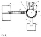
- an example of an electric motor about an axis 16 rotatable rotary indexing table 20 is provided on which 24 holding devices 22 radially arranged at an angular distance of 15 ° and / or are embedded.
- Each holding device 22 has 48 receptacles provided for alkali manganese round cells of a predeterminable type. In each case two holding devices are fastened or fixed by means of a retaining clip 16 on the rotary indexing table.
- single-grade alkaline manganese round cells of types C, D and AA and AAA can be processed as input material or energy storage.
- still conveyors 30,32 for collecting and transporting the expelled energy storage materials and storage containers 34,36 provided for their collection.
- the two conveyors include in the example shown here an angle of about 90 °, but are in principle arbitrarily arranged.
- the proposed rotary table with the radially circumferentially arranged 24 holding devices can be seen. Furthermore, the rotary indexing table on an upper rotatable mounting plate 20, in which the 24 holding devices 22 are inserted or embedded, and a rigidly arranged below the mounting plate 20 bearing plate 24.
- Fig. 4 a 3dim sectional view through the rotary table and the ejector 10 and a filled with alkali manganese round cells 28a, b holding device 22 is shown, in which case the mounting plate 20 and the bearing plate 24 of the rotary indexing table, as well as in the mounting plate 20 recessed holding devices 22 and a in the bearing plate 24 recessed die 26 is indicated.
- each holding device 22 has, as in FIG. 5 indicated a circumferential edge, with which the holding device 22 is supported on the mounting plate 20 and rests on this mounting plate.
- the used energy storage 28a, b based on the bearing plate 24, wherein in the region of the respective ejector 10, the ejectors 14 and the downholder 12 opposite in the bearing plate 24 a die 26 with through holes for the passage or passage of the energy storage cores 28d during ejection is provided.
- the bearing plate 24 is rigid and the mounting plate 20 rotatably arranged.
- a weakening device (not explicitly shown in the figures) with a pressing or punching device with one of the number of provided in the holding device energy storage recordings corresponding number of Schissechungsstkovn, in particular with radially encircling and / or star-shaped or radiating cutting edge and / or conically tapered mandrel, providable, wherein the punch are acted upon or can be acted upon with a presettable force, and from below into the receptacles of the respective holding device 22 are retracted, so that from below into the hold-down facing away and / or underlying end face or contact surface of the respective energy store 28a, 28a, 28b and in particular of the respective round cell a weakening opening or one or more weakening lines or predetermined breaking lines can be molded and / or punched in or out r are formed or punched in after insertion of the stamp.
- the hold-down 12 serves as an abutment to an upward sliding out of the energy storage 28a, b from the holding device 22 to avoid or prevent.
- all of the energy storage 28a, b and / or round cells used in a holding device 22 can be simultaneously actuated.
- liquid constituents of the respective energy store can already exit or flow downwards, for example into a corresponding gutter or trough and / or collecting container.
- a second ejector 31 is providable, wherein in the region of the second ejector 31 for the respective outer shell 28c in the bearing plate 24 at least one recess is provided, such that the arranged in the holding device 22 coreless energy storage through the mounting plate 20 and bearing plate 24 and thus the rotary indexing table are moved through and / or below the bearing plate 24, in particular by means of a conveyor 32, can be collected.
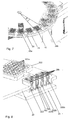
- FIG. 6 can be taken that on the rotary index table and in particular the mounting plate 20 magazine-like holding devices 22, 24 are provided in the number, which almost radially encircling, in particular with an angular distance ⁇ of 15 ° (see also Fig. 7 ) are arranged.
- At least two areas are provided with recesses in the bearing plate 24, wherein in at least a first region, a first recess is provided, in which a die 26 is inserted, which has passage openings which correspond in number and arrangement to the receptacles of at least one holding device 22 and have a cross-section and / or clear width, which is adapted to the dimensions of the core 28d of the respective energy storage type to be processed.
- Mounting plate 20 and bearing plate 24 act in such a way that the mounting plate in each case in 15 ° steps against the respective ejector 10,31 and the position plate 24 is rotationally counterclockwise rotatably movable and that the energy storage cores 28d of the respective holding device 22 down through the rotary table and in particular the mounting plate 20 and the bearing plate 24 can be expressed and / or ejected into a conveying / collecting device 30, 32, 34, 36, wherein the energy stores 28 a, b, and in particular their outer jackets 28 c, during the ejection or ejection against support the inserted die 26, and the expressed energy storage material is collected below the table 20,24 and collected by means of corresponding conveyors 30,32.
- 48 energy storage can be used in the holding device and at the same time editable, so that 48 energy storage cores 28d and only one further processing step 48 outer shells 8c and envelopes of the processed energy storage 28a, b are expressed and / or expelled in only one processing step.
- a holding device 22 takes place in two steps, wherein a 48 energy storage receiving holding device 22, as in Fig. 6 shown in two batches 28a and 28b or passes filled with 24 energy spokes in a staggered arrangement or equipped.
- the processing device comprises at least one storage bunker in which the preselected unmixed energy storage 28a, b are kept and stored for mechanical processing and transferred via a Vibra discharge chute from the storage bunker batchwise or in batches or in packets to a separation plant.
- a plurality of round brushes are providable, by means of which the linearly driven by vibration energy storage, in particular round cells, on two feed strands are transferred, wherein the respective holding device 22 are cyclically filled in parallel at two staggered points by means of the two feed strands with 24 tubing with 24 round cells and / or Zu manufacturedredundanz is formed, each holding device is finally filled with 48 cells.
- the filled with energy storage devices 28a, b holding devices 22 are further clocked after filling, that is, the mounting plate each moved by 15 °, and the filled energy storage 28a, b in the Auspressvorgang from the energy storage core, that is separated from zinc oxide, paper, brass pin, wherein the Cores 28d fall after ejection on a conveyor 30, in particular a discharge conveyor.
- the individual holding devices 22 are successively populated, ejected the energy storage cores and then ejected the remaining energy storage residues. Accordingly, 48 round cells can be processed approximately every 4 to 10 seconds
- the hold-down 12 first descends except for the holding device 22 and presses after insertion additional supernatant energy storage into the receptacles 22a of the respective holding device 22 until the energy store is flush with its top edge.
- an eccentric press with, in particular, four gas pressure pistons 16 is used.
- Such supernatant energy stores are exemplary in Fig. 8 shown.
- an optional intermediate step (which is not explicitly shown in the figures) is to facilitate or simplify the ejection process of the energy storage cores 28d weakening, in particular material weakening, the downwardly directed end, that is, the downholder 12 facing away Side of the energy storage 28a, b used in the holding device 22, in particular round cells, bewirkbar.
- the energy stores 28a, b are advantageously machined from below in the respective holding device 22 in such a way that each energy store 28a, b and / or bottom face or contact surface remote from the hold-down 12 and / or bottom face
- Each round cell is formed and / or stamped a weakening opening or recess or one or more weakening lines or predetermined breaking lines.
- the hold-down 12 serves as an abutment to an upward sliding out of the energy storage 28a, b from the holding device 22 to avoid or prevent.
- all of the energy storage 28a, b and / or round cells used in a holding device 22 can be simultaneously actuated.
- a weakening device (not explicitly shown in the figures) with a pressing or punching device having a number of weakening punches corresponding to the number of energy storage shots provided in the holding device, in particular with radially encircling and / or star-shaped or radiating, is exemplified Cutting edge and / or tapered mandrel, used or used, wherein the punch are acted upon with a presettable force or acted upon, and wherein these punch engage in the weakening process from below into the receptacles of the respective holding device 22, wherein the energy storage 28a, b, in particular Circular cells are processed from below such that in the down side facing away from the down and / or lying end face or contact surface of the respective energy storage 287a, b and in particular the respective round cell an attenuation opening or one or more re weakening lines or predetermined breaking lines are formed and / or stamped or are.
- the ejectors 14 are then lowered through the through holes of the blank holder 12 in the energy storage 28a, b and the receptacles 22a of the respective holding device 22 and thus push the energy storage cores from the energy storage down.
- the hold-down 12 initially remains on the respective holding device 22 during the retraction until the ejector 14 are again outside the energy storage. Then also the hold-down 12 is raised again or withdrawn.
- the hold-down 12 By means of the hold-down 12 is avoided that the energy storage remains stuck to the ejectors 14 and are removed with these from the holding device 22. Accordingly, the hold-down holds the energy storage during the entire ejection process of the cores in position and fixes them in the holding device.
- the holding-down device 12 shown here by way of example is designed as a plate with recesses or passages arranged in grid fashion, in particular in the form of through-holes, the grid corresponding to the grid of the ejection device 10 and the holding device 22 and the cross-section of the recesses to the cross-section of the individual ejectors 14 is adjusted.
- the contact surface of the respective ejector 14 is to facilitate the Ausforcerithticians formed as a flat surface with a radially circumferential cutting edge.
- the remaining in the holding device energy storage residues are after further movement or rotation of the bearing plate by means of a second ejection device 31 by at least one further recess in the bearing plate 24th pushed through and collected below the bearing plate and collected.
- a significantly lower force required for this purpose than when ejecting the energy storage cores.
- FIGS. 4 to 7 Removable comprises the example designed according to the invention processing device for the utilization of electrochemical energy storage and in particular for alkali-manganese round cells, 24 magazine-like holding devices 22 and two complementary trained ejection devices, wherein the respective holding device 22 has a plurality, in particular 48 arranged in a grid energy storage receptacles 22a and each of these receptacles 22a is formed as a cylinder-like recess and in cross-section and / or clear width and / or dimension are adapted to the dimensions of the respective energy storage type to be processed 28a, b, and the ejector 10,31 more arranged in the grid of the holding device ejector 14th and each ejector 14 is designed as a cylinder-like pin or pin, which in cross-section and / or dimension to the dimensions of the respective energy storage core 28d or the respective energy storage to be processed s 28a, b itself is adjusted.
- the bearing plate 224 is disposed below the respective holding means 222, so that the holding means 222 between the bearing plate 224 and ejector can be positioned and / or arranged.
- a cross-sectional constriction 222b in particular in the form of three inwardly directed projections on which the energy storage 28a, b are supported and / or rest after filling or insertion in the holding device 222 ,
- the three projections are arranged uniformly distributed over the inner circumference of the receptacle 222a. To damage the respective ejector to avoid this is advantageously adapted to the geometry and dimension, in particular with regard to length, height width, the cross-sectional constriction 222b and in particular the three projections.
Landscapes
- Engineering & Computer Science (AREA)
- Manufacturing & Machinery (AREA)
- Chemical & Material Sciences (AREA)
- Chemical Kinetics & Catalysis (AREA)
- Electrochemistry (AREA)
- General Chemical & Material Sciences (AREA)
- Primary Cells (AREA)
Applications Claiming Priority (1)
| Application Number | Priority Date | Filing Date | Title |
|---|---|---|---|
| DE102015006530 | 2015-05-27 |
Publications (2)
| Publication Number | Publication Date |
|---|---|
| EP3098884A1 true EP3098884A1 (fr) | 2016-11-30 |
| EP3098884B1 EP3098884B1 (fr) | 2018-02-14 |
Family
ID=56292414
Family Applications (1)
| Application Number | Title | Priority Date | Filing Date |
|---|---|---|---|
| EP16001176.3A Not-in-force EP3098884B1 (fr) | 2015-05-27 | 2016-05-24 | Dispositif et procédé de traitement pour la récupération d'accumulateurs d'énergie électrochimiques |
Country Status (2)
| Country | Link |
|---|---|
| EP (1) | EP3098884B1 (fr) |
| DE (1) | DE102016006176A1 (fr) |
Cited By (4)
| Publication number | Priority date | Publication date | Assignee | Title |
|---|---|---|---|---|
| CN113764761A (zh) * | 2021-08-13 | 2021-12-07 | 安徽绿沃循环能源科技有限公司 | 一种锂电池组拆分回收装置 |
| CN113851749A (zh) * | 2021-08-13 | 2021-12-28 | 安徽绿沃循环能源科技有限公司 | 一种电池组内部电池液检测回收装置 |
| CN114156498A (zh) * | 2021-11-05 | 2022-03-08 | 合肥众禾动力新能源科技有限公司 | 一种圆柱电芯剥壳结构 |
| EP4095995A1 (fr) * | 2021-05-27 | 2022-11-30 | Wilhelm Bahmüller Maschinenbau-Präzisionswerkzeuge GmbH | Dispositif d'équipement des porte-cellules des accumulateurs |
Citations (4)
| Publication number | Priority date | Publication date | Assignee | Title |
|---|---|---|---|---|
| EP0452564A1 (fr) * | 1990-03-26 | 1991-10-23 | Fémmü, Csepel Müvek | Procédé et dispositif pour la récupération de composants de batteries sèches |
| CN2925654Y (zh) * | 2006-06-15 | 2007-07-25 | 深圳市格林美高新技术有限公司 | 废弃电池立式破壳机 |
| EP2182569B1 (fr) | 2008-10-29 | 2013-01-16 | REDUX Technology GmbH | Procédé et appareil pour le recyclage d'un accumulateur d'énergie électrochimique |
| CN104868138A (zh) * | 2015-05-03 | 2015-08-26 | 谢洁萍 | 一种废旧干电池的回收处理装置 |
-
2016
- 2016-05-24 EP EP16001176.3A patent/EP3098884B1/fr not_active Not-in-force
- 2016-05-24 DE DE102016006176.6A patent/DE102016006176A1/de not_active Withdrawn
Patent Citations (4)
| Publication number | Priority date | Publication date | Assignee | Title |
|---|---|---|---|---|
| EP0452564A1 (fr) * | 1990-03-26 | 1991-10-23 | Fémmü, Csepel Müvek | Procédé et dispositif pour la récupération de composants de batteries sèches |
| CN2925654Y (zh) * | 2006-06-15 | 2007-07-25 | 深圳市格林美高新技术有限公司 | 废弃电池立式破壳机 |
| EP2182569B1 (fr) | 2008-10-29 | 2013-01-16 | REDUX Technology GmbH | Procédé et appareil pour le recyclage d'un accumulateur d'énergie électrochimique |
| CN104868138A (zh) * | 2015-05-03 | 2015-08-26 | 谢洁萍 | 一种废旧干电池的回收处理装置 |
Cited By (6)
| Publication number | Priority date | Publication date | Assignee | Title |
|---|---|---|---|---|
| EP4095995A1 (fr) * | 2021-05-27 | 2022-11-30 | Wilhelm Bahmüller Maschinenbau-Präzisionswerkzeuge GmbH | Dispositif d'équipement des porte-cellules des accumulateurs |
| CN113764761A (zh) * | 2021-08-13 | 2021-12-07 | 安徽绿沃循环能源科技有限公司 | 一种锂电池组拆分回收装置 |
| CN113851749A (zh) * | 2021-08-13 | 2021-12-28 | 安徽绿沃循环能源科技有限公司 | 一种电池组内部电池液检测回收装置 |
| CN113851749B (zh) * | 2021-08-13 | 2023-11-03 | 安徽绿沃循环能源科技有限公司 | 一种电池组内部电池液检测回收装置 |
| CN114156498A (zh) * | 2021-11-05 | 2022-03-08 | 合肥众禾动力新能源科技有限公司 | 一种圆柱电芯剥壳结构 |
| CN114156498B (zh) * | 2021-11-05 | 2024-02-27 | 合肥众禾动力新能源科技有限公司 | 一种圆柱电芯剥壳结构 |
Also Published As
| Publication number | Publication date |
|---|---|
| DE102016006176A1 (de) | 2016-12-01 |
| EP3098884B1 (fr) | 2018-02-14 |
Similar Documents
| Publication | Publication Date | Title |
|---|---|---|
| EP3098884B1 (fr) | Dispositif et procédé de traitement pour la récupération d'accumulateurs d'énergie électrochimiques | |
| EP2182569B1 (fr) | Procédé et appareil pour le recyclage d'un accumulateur d'énergie électrochimique | |
| EP3746576A1 (fr) | Procédé de recyclage de batteries au lithium | |
| WO2018233774A1 (fr) | Dispositif et procédé servant à fabriquer un élément de machine pourvu d'enroulements pour une machine électrique | |
| EP3863161B1 (fr) | Dispositif d'assemblage et système comprenant un dispositif d'assemblage et un rotor | |
| EP3222414B1 (fr) | Presse a comprimes rotative comprenant des poinçons ayant au moins deux pointes de poinçons echelonnees en hauteur destinee a executer plusieurs procedes de presse pendant une rotation | |
| DE69125269T2 (de) | Verfahren zum bau einer bleisäurebatterie und dementsprechende vorrichtung | |
| DE10013690A1 (de) | Verfahren zur Herstellung von aus Blechteilen bestehenden Paketen | |
| WO2012152412A1 (fr) | Dispositif permettant d'ouvrir et de vider des gélules remplies | |
| EP3182569B1 (fr) | Dispositif et procede d'introduction d'une enroulement ondulé d'une natte des enroulements ondulés prefabriqués dans les encoches d'un empilage de tôles de stator | |
| EP2592703A2 (fr) | Dispositif d'alimentation variable pour un agrégat de sertissage | |
| DE4009830C1 (fr) | ||
| EP4304063B1 (fr) | Machine de tri et installation de fabrication ainsi que procédé de tri pour barres conductrices | |
| EP4325614A1 (fr) | Procédé de préparation d'accumulateurs | |
| DE102018109706B4 (de) | Bestückungsstation zur Bestückung einer Rotoreinheit oder eines Hilfswerkzeugs mit Magnetelementen und Verfahren zum Bestücken einer ringförmigen Rotoreinheit für einen Elektromotor mit Magnetelementen | |
| DE19914688A1 (de) | Verfahren und System zum Entfernen einer Explosivladung aus Hohlladungsmunition | |
| EP3278886A1 (fr) | Procédé et dispositif de recyclage de récipients fermés et remplis de poudre | |
| WO2014020005A1 (fr) | Dispositif et procédé de fabrication d'un élément accumulateur d'énergie | |
| DE102012007357B4 (de) | Blechbearbeitungswerkzeug mit einer Stanz-Einpress-Vorrichtung und einem im Werkzeugoberteil angeordneten Abfallkanal zur Ausleitung von ausgestanzten Lochabfallstücken | |
| DE1627688A1 (de) | Verfahren und Vorrichtung fuer das Warmverformen von kopfprofilierten Elementen wie Bolzen,Stifte,Stanzstempel u.dgl.auf Matrizen | |
| EP2984191A1 (fr) | Procédé et dispositif d'extraction de résidus de métaux ferreux purs et libres contenus dans un mélange de déchets métalliques broyés | |
| DE102021119930B3 (de) | Vorrichtung und Verfahren zum Herstellen von Formteilen aus erwärmter thermoplastischer Kunststofffolie | |
| AT387329B (de) | Verfahren und vorrichtung zur rueckgewinnung von golfball-kernen | |
| EP0994539B1 (fr) | Dispositif pour l'assemblage d'un câble | |
| DE102024134438B4 (de) | Vorrichtung zur Herstellung eines Snackprodukts auf der Basis einer Eiswaffel |
Legal Events
| Date | Code | Title | Description |
|---|---|---|---|
| PUAI | Public reference made under article 153(3) epc to a published international application that has entered the european phase |
Free format text: ORIGINAL CODE: 0009012 |
|
| AK | Designated contracting states |
Kind code of ref document: A1 Designated state(s): AL AT BE BG CH CY CZ DE DK EE ES FI FR GB GR HR HU IE IS IT LI LT LU LV MC MK MT NL NO PL PT RO RS SE SI SK SM TR |
|
| AX | Request for extension of the european patent |
Extension state: BA ME |
|
| 17P | Request for examination filed |
Effective date: 20161028 |
|
| GRAP | Despatch of communication of intention to grant a patent |
Free format text: ORIGINAL CODE: EPIDOSNIGR1 |
|
| INTG | Intention to grant announced |
Effective date: 20170510 |
|
| GRAJ | Information related to disapproval of communication of intention to grant by the applicant or resumption of examination proceedings by the epo deleted |
Free format text: ORIGINAL CODE: EPIDOSDIGR1 |
|
| INTC | Intention to grant announced (deleted) | ||
| GRAP | Despatch of communication of intention to grant a patent |
Free format text: ORIGINAL CODE: EPIDOSNIGR1 |
|
| GRAS | Grant fee paid |
Free format text: ORIGINAL CODE: EPIDOSNIGR3 |
|
| GRAJ | Information related to disapproval of communication of intention to grant by the applicant or resumption of examination proceedings by the epo deleted |
Free format text: ORIGINAL CODE: EPIDOSDIGR1 |
|
| GRAL | Information related to payment of fee for publishing/printing deleted |
Free format text: ORIGINAL CODE: EPIDOSDIGR3 |
|
| INTG | Intention to grant announced |
Effective date: 20170510 |
|
| GRAP | Despatch of communication of intention to grant a patent |
Free format text: ORIGINAL CODE: EPIDOSNIGR1 |
|
| INTC | Intention to grant announced (deleted) | ||
| INTG | Intention to grant announced |
Effective date: 20171011 |
|
| GRAA | (expected) grant |
Free format text: ORIGINAL CODE: 0009210 |
|
| AK | Designated contracting states |
Kind code of ref document: B1 Designated state(s): AL AT BE BG CH CY CZ DE DK EE ES FI FR GB GR HR HU IE IS IT LI LT LU LV MC MK MT NL NO PL PT RO RS SE SI SK SM TR |
|
| REG | Reference to a national code |
Ref country code: GB Ref legal event code: FG4D Free format text: NOT ENGLISH |
|
| REG | Reference to a national code |
Ref country code: CH Ref legal event code: EP |
|
| REG | Reference to a national code |
Ref country code: IE Ref legal event code: FG4D Free format text: LANGUAGE OF EP DOCUMENT: GERMAN |
|
| REG | Reference to a national code |
Ref country code: DE Ref legal event code: R096 Ref document number: 502016000562 Country of ref document: DE Ref country code: AT Ref legal event code: REF Ref document number: 970414 Country of ref document: AT Kind code of ref document: T Effective date: 20180315 |
|
| REG | Reference to a national code |
Ref country code: FR Ref legal event code: PLFP Year of fee payment: 3 |
|
| REG | Reference to a national code |
Ref country code: NL Ref legal event code: MP Effective date: 20180214 |
|
| PG25 | Lapsed in a contracting state [announced via postgrant information from national office to epo] |
Ref country code: ES Free format text: LAPSE BECAUSE OF FAILURE TO SUBMIT A TRANSLATION OF THE DESCRIPTION OR TO PAY THE FEE WITHIN THE PRESCRIBED TIME-LIMIT Effective date: 20180214 Ref country code: NL Free format text: LAPSE BECAUSE OF FAILURE TO SUBMIT A TRANSLATION OF THE DESCRIPTION OR TO PAY THE FEE WITHIN THE PRESCRIBED TIME-LIMIT Effective date: 20180214 Ref country code: CY Free format text: LAPSE BECAUSE OF FAILURE TO SUBMIT A TRANSLATION OF THE DESCRIPTION OR TO PAY THE FEE WITHIN THE PRESCRIBED TIME-LIMIT Effective date: 20180214 Ref country code: LT Free format text: LAPSE BECAUSE OF FAILURE TO SUBMIT A TRANSLATION OF THE DESCRIPTION OR TO PAY THE FEE WITHIN THE PRESCRIBED TIME-LIMIT Effective date: 20180214 Ref country code: NO Free format text: LAPSE BECAUSE OF FAILURE TO SUBMIT A TRANSLATION OF THE DESCRIPTION OR TO PAY THE FEE WITHIN THE PRESCRIBED TIME-LIMIT Effective date: 20180514 Ref country code: FI Free format text: LAPSE BECAUSE OF FAILURE TO SUBMIT A TRANSLATION OF THE DESCRIPTION OR TO PAY THE FEE WITHIN THE PRESCRIBED TIME-LIMIT Effective date: 20180214 Ref country code: HR Free format text: LAPSE BECAUSE OF FAILURE TO SUBMIT A TRANSLATION OF THE DESCRIPTION OR TO PAY THE FEE WITHIN THE PRESCRIBED TIME-LIMIT Effective date: 20180214 |
|
| PG25 | Lapsed in a contracting state [announced via postgrant information from national office to epo] |
Ref country code: RS Free format text: LAPSE BECAUSE OF FAILURE TO SUBMIT A TRANSLATION OF THE DESCRIPTION OR TO PAY THE FEE WITHIN THE PRESCRIBED TIME-LIMIT Effective date: 20180214 Ref country code: GR Free format text: LAPSE BECAUSE OF FAILURE TO SUBMIT A TRANSLATION OF THE DESCRIPTION OR TO PAY THE FEE WITHIN THE PRESCRIBED TIME-LIMIT Effective date: 20180515 Ref country code: SE Free format text: LAPSE BECAUSE OF FAILURE TO SUBMIT A TRANSLATION OF THE DESCRIPTION OR TO PAY THE FEE WITHIN THE PRESCRIBED TIME-LIMIT Effective date: 20180214 Ref country code: LV Free format text: LAPSE BECAUSE OF FAILURE TO SUBMIT A TRANSLATION OF THE DESCRIPTION OR TO PAY THE FEE WITHIN THE PRESCRIBED TIME-LIMIT Effective date: 20180214 Ref country code: BG Free format text: LAPSE BECAUSE OF FAILURE TO SUBMIT A TRANSLATION OF THE DESCRIPTION OR TO PAY THE FEE WITHIN THE PRESCRIBED TIME-LIMIT Effective date: 20180514 |
|
| PG25 | Lapsed in a contracting state [announced via postgrant information from national office to epo] |
Ref country code: MT Free format text: LAPSE BECAUSE OF FAILURE TO SUBMIT A TRANSLATION OF THE DESCRIPTION OR TO PAY THE FEE WITHIN THE PRESCRIBED TIME-LIMIT Effective date: 20180214 |
|
| PG25 | Lapsed in a contracting state [announced via postgrant information from national office to epo] |
Ref country code: IT Free format text: LAPSE BECAUSE OF FAILURE TO SUBMIT A TRANSLATION OF THE DESCRIPTION OR TO PAY THE FEE WITHIN THE PRESCRIBED TIME-LIMIT Effective date: 20180214 Ref country code: RO Free format text: LAPSE BECAUSE OF FAILURE TO SUBMIT A TRANSLATION OF THE DESCRIPTION OR TO PAY THE FEE WITHIN THE PRESCRIBED TIME-LIMIT Effective date: 20180214 Ref country code: PL Free format text: LAPSE BECAUSE OF FAILURE TO SUBMIT A TRANSLATION OF THE DESCRIPTION OR TO PAY THE FEE WITHIN THE PRESCRIBED TIME-LIMIT Effective date: 20180214 Ref country code: AL Free format text: LAPSE BECAUSE OF FAILURE TO SUBMIT A TRANSLATION OF THE DESCRIPTION OR TO PAY THE FEE WITHIN THE PRESCRIBED TIME-LIMIT Effective date: 20180214 Ref country code: EE Free format text: LAPSE BECAUSE OF FAILURE TO SUBMIT A TRANSLATION OF THE DESCRIPTION OR TO PAY THE FEE WITHIN THE PRESCRIBED TIME-LIMIT Effective date: 20180214 |
|
| REG | Reference to a national code |
Ref country code: DE Ref legal event code: R097 Ref document number: 502016000562 Country of ref document: DE |
|
| PG25 | Lapsed in a contracting state [announced via postgrant information from national office to epo] |
Ref country code: DK Free format text: LAPSE BECAUSE OF FAILURE TO SUBMIT A TRANSLATION OF THE DESCRIPTION OR TO PAY THE FEE WITHIN THE PRESCRIBED TIME-LIMIT Effective date: 20180214 Ref country code: SM Free format text: LAPSE BECAUSE OF FAILURE TO SUBMIT A TRANSLATION OF THE DESCRIPTION OR TO PAY THE FEE WITHIN THE PRESCRIBED TIME-LIMIT Effective date: 20180214 Ref country code: CZ Free format text: LAPSE BECAUSE OF FAILURE TO SUBMIT A TRANSLATION OF THE DESCRIPTION OR TO PAY THE FEE WITHIN THE PRESCRIBED TIME-LIMIT Effective date: 20180214 Ref country code: SK Free format text: LAPSE BECAUSE OF FAILURE TO SUBMIT A TRANSLATION OF THE DESCRIPTION OR TO PAY THE FEE WITHIN THE PRESCRIBED TIME-LIMIT Effective date: 20180214 |
|
| PLBE | No opposition filed within time limit |
Free format text: ORIGINAL CODE: 0009261 |
|
| STAA | Information on the status of an ep patent application or granted ep patent |
Free format text: STATUS: NO OPPOSITION FILED WITHIN TIME LIMIT |
|
| 26N | No opposition filed |
Effective date: 20181115 |
|
| REG | Reference to a national code |
Ref country code: BE Ref legal event code: MM Effective date: 20180531 |
|
| PG25 | Lapsed in a contracting state [announced via postgrant information from national office to epo] |
Ref country code: MC Free format text: LAPSE BECAUSE OF FAILURE TO SUBMIT A TRANSLATION OF THE DESCRIPTION OR TO PAY THE FEE WITHIN THE PRESCRIBED TIME-LIMIT Effective date: 20180214 |
|
| REG | Reference to a national code |
Ref country code: IE Ref legal event code: MM4A |
|
| PG25 | Lapsed in a contracting state [announced via postgrant information from national office to epo] |
Ref country code: SI Free format text: LAPSE BECAUSE OF FAILURE TO SUBMIT A TRANSLATION OF THE DESCRIPTION OR TO PAY THE FEE WITHIN THE PRESCRIBED TIME-LIMIT Effective date: 20180214 |
|
| PG25 | Lapsed in a contracting state [announced via postgrant information from national office to epo] |
Ref country code: LU Free format text: LAPSE BECAUSE OF NON-PAYMENT OF DUE FEES Effective date: 20180524 |
|
| PG25 | Lapsed in a contracting state [announced via postgrant information from national office to epo] |
Ref country code: IE Free format text: LAPSE BECAUSE OF NON-PAYMENT OF DUE FEES Effective date: 20180524 |
|
| PG25 | Lapsed in a contracting state [announced via postgrant information from national office to epo] |
Ref country code: BE Free format text: LAPSE BECAUSE OF NON-PAYMENT OF DUE FEES Effective date: 20180531 |
|
| PG25 | Lapsed in a contracting state [announced via postgrant information from national office to epo] |
Ref country code: TR Free format text: LAPSE BECAUSE OF FAILURE TO SUBMIT A TRANSLATION OF THE DESCRIPTION OR TO PAY THE FEE WITHIN THE PRESCRIBED TIME-LIMIT Effective date: 20180214 |
|
| PG25 | Lapsed in a contracting state [announced via postgrant information from national office to epo] |
Ref country code: PT Free format text: LAPSE BECAUSE OF FAILURE TO SUBMIT A TRANSLATION OF THE DESCRIPTION OR TO PAY THE FEE WITHIN THE PRESCRIBED TIME-LIMIT Effective date: 20180214 |
|
| PG25 | Lapsed in a contracting state [announced via postgrant information from national office to epo] |
Ref country code: HU Free format text: LAPSE BECAUSE OF FAILURE TO SUBMIT A TRANSLATION OF THE DESCRIPTION OR TO PAY THE FEE WITHIN THE PRESCRIBED TIME-LIMIT; INVALID AB INITIO Effective date: 20160524 Ref country code: MK Free format text: LAPSE BECAUSE OF NON-PAYMENT OF DUE FEES Effective date: 20180214 |
|
| PG25 | Lapsed in a contracting state [announced via postgrant information from national office to epo] |
Ref country code: IS Free format text: LAPSE BECAUSE OF FAILURE TO SUBMIT A TRANSLATION OF THE DESCRIPTION OR TO PAY THE FEE WITHIN THE PRESCRIBED TIME-LIMIT Effective date: 20180614 |
|
| PGFP | Annual fee paid to national office [announced via postgrant information from national office to epo] |
Ref country code: FR Payment date: 20200519 Year of fee payment: 5 |
|
| PGFP | Annual fee paid to national office [announced via postgrant information from national office to epo] |
Ref country code: GB Payment date: 20200522 Year of fee payment: 5 |
|
| PGFP | Annual fee paid to national office [announced via postgrant information from national office to epo] |
Ref country code: CH Payment date: 20210525 Year of fee payment: 6 Ref country code: AT Payment date: 20210518 Year of fee payment: 6 |
|
| GBPC | Gb: european patent ceased through non-payment of renewal fee |
Effective date: 20210524 |
|
| PG25 | Lapsed in a contracting state [announced via postgrant information from national office to epo] |
Ref country code: GB Free format text: LAPSE BECAUSE OF NON-PAYMENT OF DUE FEES Effective date: 20210524 |
|
| PG25 | Lapsed in a contracting state [announced via postgrant information from national office to epo] |
Ref country code: FR Free format text: LAPSE BECAUSE OF NON-PAYMENT OF DUE FEES Effective date: 20210531 |
|
| PGFP | Annual fee paid to national office [announced via postgrant information from national office to epo] |
Ref country code: DE Payment date: 20220519 Year of fee payment: 7 |
|
| REG | Reference to a national code |
Ref country code: CH Ref legal event code: PL |
|
| REG | Reference to a national code |
Ref country code: AT Ref legal event code: MM01 Ref document number: 970414 Country of ref document: AT Kind code of ref document: T Effective date: 20220524 |
|
| PG25 | Lapsed in a contracting state [announced via postgrant information from national office to epo] |
Ref country code: LI Free format text: LAPSE BECAUSE OF NON-PAYMENT OF DUE FEES Effective date: 20220531 Ref country code: CH Free format text: LAPSE BECAUSE OF NON-PAYMENT OF DUE FEES Effective date: 20220531 Ref country code: AT Free format text: LAPSE BECAUSE OF NON-PAYMENT OF DUE FEES Effective date: 20220524 |
|
| REG | Reference to a national code |
Ref country code: DE Ref legal event code: R119 Ref document number: 502016000562 Country of ref document: DE |
|
| PG25 | Lapsed in a contracting state [announced via postgrant information from national office to epo] |
Ref country code: DE Free format text: LAPSE BECAUSE OF NON-PAYMENT OF DUE FEES Effective date: 20231201 |