EP3099152A1 - Geschlossener schrank für elektrische vorrichtung mit wärmerohr - Google Patents
Geschlossener schrank für elektrische vorrichtung mit wärmerohr Download PDFInfo
- Publication number
- EP3099152A1 EP3099152A1 EP16169359.3A EP16169359A EP3099152A1 EP 3099152 A1 EP3099152 A1 EP 3099152A1 EP 16169359 A EP16169359 A EP 16169359A EP 3099152 A1 EP3099152 A1 EP 3099152A1
- Authority
- EP
- European Patent Office
- Prior art keywords
- heat dissipation
- heat
- cabinet
- accommodation space
- closed cabinet
- Prior art date
- Legal status (The legal status is an assumption and is not a legal conclusion. Google has not performed a legal analysis and makes no representation as to the accuracy of the status listed.)
- Withdrawn
Links
- 230000017525 heat dissipation Effects 0.000 claims abstract description 141
- 230000004308 accommodation Effects 0.000 claims abstract description 30
- 238000010438 heat treatment Methods 0.000 claims abstract description 10
- 239000012530 fluid Substances 0.000 claims description 3
- 230000002708 enhancing effect Effects 0.000 abstract description 2
- 239000013529 heat transfer fluid Substances 0.000 description 10
- 238000001816 cooling Methods 0.000 description 7
- 238000009434 installation Methods 0.000 description 6
- 230000005494 condensation Effects 0.000 description 5
- 238000009833 condensation Methods 0.000 description 5
- 238000001704 evaporation Methods 0.000 description 4
- 230000008020 evaporation Effects 0.000 description 4
- 230000000694 effects Effects 0.000 description 3
- 239000000126 substance Substances 0.000 description 3
- 239000000428 dust Substances 0.000 description 1
- 230000005484 gravity Effects 0.000 description 1
- 230000007257 malfunction Effects 0.000 description 1
- 230000003252 repetitive effect Effects 0.000 description 1
- 150000003839 salts Chemical class 0.000 description 1
- 239000004065 semiconductor Substances 0.000 description 1
- XLYOFNOQVPJJNP-UHFFFAOYSA-N water Substances O XLYOFNOQVPJJNP-UHFFFAOYSA-N 0.000 description 1
Images



Classifications
-
- H—ELECTRICITY
- H05—ELECTRIC TECHNIQUES NOT OTHERWISE PROVIDED FOR
- H05K—PRINTED CIRCUITS; CASINGS OR CONSTRUCTIONAL DETAILS OF ELECTRIC APPARATUS; MANUFACTURE OF ASSEMBLAGES OF ELECTRICAL COMPONENTS
- H05K7/00—Constructional details common to different types of electric apparatus
- H05K7/20—Modifications to facilitate cooling, ventilating, or heating
- H05K7/2089—Modifications to facilitate cooling, ventilating, or heating for power electronics, e.g. for inverters for controlling motor
- H05K7/20936—Liquid coolant with phase change
-
- H—ELECTRICITY
- H05—ELECTRIC TECHNIQUES NOT OTHERWISE PROVIDED FOR
- H05K—PRINTED CIRCUITS; CASINGS OR CONSTRUCTIONAL DETAILS OF ELECTRIC APPARATUS; MANUFACTURE OF ASSEMBLAGES OF ELECTRICAL COMPONENTS
- H05K7/00—Constructional details common to different types of electric apparatus
- H05K7/20—Modifications to facilitate cooling, ventilating, or heating
- H05K7/20009—Modifications to facilitate cooling, ventilating, or heating using a gaseous coolant in electronic enclosures
- H05K7/20136—Forced ventilation, e.g. by fans
- H05K7/20154—Heat dissipaters coupled to components
- H05K7/20163—Heat dissipaters coupled to components the components being isolated from air flow, e.g. hollow heat sinks, wind tunnels or funnels
-
- H—ELECTRICITY
- H05—ELECTRIC TECHNIQUES NOT OTHERWISE PROVIDED FOR
- H05K—PRINTED CIRCUITS; CASINGS OR CONSTRUCTIONAL DETAILS OF ELECTRIC APPARATUS; MANUFACTURE OF ASSEMBLAGES OF ELECTRICAL COMPONENTS
- H05K7/00—Constructional details common to different types of electric apparatus
- H05K7/20—Modifications to facilitate cooling, ventilating, or heating
- H05K7/2029—Modifications to facilitate cooling, ventilating, or heating using a liquid coolant with phase change in electronic enclosures
- H05K7/20336—Heat pipes, e.g. wicks or capillary pumps
-
- H—ELECTRICITY
- H05—ELECTRIC TECHNIQUES NOT OTHERWISE PROVIDED FOR
- H05K—PRINTED CIRCUITS; CASINGS OR CONSTRUCTIONAL DETAILS OF ELECTRIC APPARATUS; MANUFACTURE OF ASSEMBLAGES OF ELECTRICAL COMPONENTS
- H05K7/00—Constructional details common to different types of electric apparatus
- H05K7/20—Modifications to facilitate cooling, ventilating, or heating
- H05K7/20009—Modifications to facilitate cooling, ventilating, or heating using a gaseous coolant in electronic enclosures
- H05K7/20136—Forced ventilation, e.g. by fans
- H05K7/20145—Means for directing air flow, e.g. ducts, deflectors, plenum or guides
-
- H—ELECTRICITY
- H05—ELECTRIC TECHNIQUES NOT OTHERWISE PROVIDED FOR
- H05K—PRINTED CIRCUITS; CASINGS OR CONSTRUCTIONAL DETAILS OF ELECTRIC APPARATUS; MANUFACTURE OF ASSEMBLAGES OF ELECTRICAL COMPONENTS
- H05K7/00—Constructional details common to different types of electric apparatus
- H05K7/20—Modifications to facilitate cooling, ventilating, or heating
- H05K7/2089—Modifications to facilitate cooling, ventilating, or heating for power electronics, e.g. for inverters for controlling motor
- H05K7/20909—Forced ventilation, e.g. on heat dissipaters coupled to components
- H05K7/20918—Forced ventilation, e.g. on heat dissipaters coupled to components the components being isolated from air flow, e.g. hollow heat sinks, wind tunnels or funnels
Definitions
- the present invention relates to a cabinet for electric device and, more particularly, a closed cabinet for electric devices which has a heat pipe capable of efficiently dissipating heat generated from internal devices, implementing compact design of the cabinet and enhancing durability of the internal devices.
- a cabinet for electric devices includes multiple internal devices (e.g., an inverter) generating heat.
- internal devices e.g., an inverter
- the cabinet is provided with heat dissipation means to ensure that the internal devices can operate at a proper temperature.
- Fig. 1 is a view illustrating a medium/large-size inverter cabinet which is a kind of cabinet for electric devices.
- the medium/large-size inverter cabinet 10 accommodates various electric and electronic components including an inverter.
- the medium/large-size inverter cabinet 10 is provided therein with a device accommodation space configured to have multiple layers to accommodate electric devices, and electric devices 20 are accommodated in each layer in the device accommodation space.
- the medium/large-size inverter cabinet 10 is structured to dissipate heat generated from the electric devices 20.
- the heat dissipation is implemented by cooling the devices with suctioned external air.
- an intake port 14 is provided in one surface of the medium/large-size inverter cabinet 10, and a heat dissipation fan 16 is provided to an upper portion of the medium/large-size inverter cabinet 10.
- the heat dissipation fan 16 is driven to introduce external cool air into the cabinet 10 and discharge the internal air from the cabinet 10.
- the cooling operation is performed in a manner that fresh air introduced from the outside cools the interior of the cabinet and is then discharged from the cabinet according to subsequent introduction of air.
- a heat dissipation fin 24 is attached to one surface of the heating element 22.
- the structure of the cabinet may become complex and large.
- a filter is installed, the resistance against suction may increase due to the installed filter, and thus a fan of a higher capacity needs to be used to secure an air flow rate and velocity needed to implement the cooling. If a fan having a high capacity is used, power consumption increases. In addition, the filter needs to be regularly cleaned and replaced.
- the heat dissipation fan 16 since the heat dissipation fan 16 is provided to the exterior of the cabinet 10, the heat dissipation fan 16 cannot be protected from water and foreign substances may be stuck to the heat dissipation fan. Thereby, the service life of the heat dissipation fan 16 may be shortened or malfunction may easily occur. In addition, if the heat dissipation fan 16 does not operate normally, heat dissipation efficiency of the cabinet for electric devices may be degraded, and accordingly the internal electronic components may be overrated and damaged or the service lives thereof may be shortened.
- a closed cabinet for an electric device includes: a device accommodation space providing a closed space to accommodate the electric device; a heat dissipation duct provided separately from the device accommodation space to dissipate heat generated from the device accommodation space; and a heat dissipation means including: a heat sink attached to a heating element of the device accommodation space; a heat dissipation fin disposed in the heat dissipation duct; a heat pipe configured to transfer heat of the heat sink to the heat dissipation fin.
- the heat dissipation duct is vertically arranged to allow external air introduced thereinto to flow upward.
- the closed cabinet further includes a heat dissipation fan configured to accelerate flow of the air in the heat dissipation duct.
- a section of the heat pipe coupled to the heat dissipation fin may be inclined upward.
- the heat dissipation fin is disposed in a vertical direction to increase an area of contact between the heat dissipation fin and the heat pipe.
- the heat pipe may be disposed in a horizontal direction and provided therein with a wick to return a heat exchange fluid to the heat sink.
- the heat dissipation fin may be attached to the heat pipe in an inclined manner.
- the heat dissipation means is disposed in a plurality of layers in the closed cabinet, wherein the heat dissipation fin of the heat dissipation means 160 in an upper layer has a relatively wider heat exchange area.
- external air does not circulate through a device accommodation space accommodating electric devices, but is introduced into a separately provided heat dissipation duct to perform the cooling operation.
- the electric device accommodation space may be prevented from being contaminated by rainwater or foreign substances introduced into the space along with the external air.
- the closed cabinet for electric devices employs a heat pipe.
- heat generated from heating elements may be effectively dissipated.
- Fig. 2 is a view illustrating configuration of a closed cabinet for electric devices according to an embodiment of the present invention.
- a closed cabinet 100 for electric devices includes a device accommodation space 120 for accommodating electric devices in a stacking manner, a heat dissipation duct 140 configured to dissipate heat generated from the device accommodation space 120, and a heat dissipation means 160 configured to discharge heat generated from a heating element 125 disposed in the device accommodation space 120 to the heat dissipation duct 140.
- the term “closed” means that the device accommodation space 120 for accommodating electric devices is closed.
- the term “closed” does not mean “completely sealed”, but means that the electric device cabinet of the present invention does not allow introduction of external air into the device accommodation space 120 in contrast with the conventional electric device cabinets, which allows external air to be introduced into the electric device accommodation space to circulate therein.
- the cabinet 100 for electric devices is provided with the heat dissipation duct 140 separately from the device accommodation space 120 for accommodating electric devices.
- external air is introduced into the heat dissipation duct 140 to dissipate heat generated from the electric devices in an air-cooling manner. Accordingly, external air need not be introduced into the device accommodation space 120, and thus foreign substances or rainwater in the external air may be prevented from contaminating the device accommodation space 120.
- the heat dissipation duct 140 may be formed to have a vertical flow path. Since heated air flow upward, the heat dissipation duct 144 formed to have a vertical flow path may cause the air in the heat dissipation duct 140 to be discharged upward through natural convection.
- a lower portion of the heat dissipation duct 140 may be provided with an introduction port 142, and an upper portion of the heat dissipation duct 140 may be provided with a discharge port 144. While the discharge port 144 is illustrated as being provided with a heat dissipation fan 145, the heat dissipation fan may be provided to the introduction port 142, or heat dissipation fans may be provided to both the introduction port 142 and the discharge port 144.
- the heat dissipation fan provided to the introduction port 142 operates to introduce external air into the heat dissipation duct 140, and the heat dissipation fan 145 provided to the discharge port 144 operates to discharge air from the heat dissipation duct 140.
- the heat dissipation means 160 provided to the cabinet 100 for electric devices includes a heat sink 162 attached to the heating element 125 accommodated in the device accommodation space 120, a heat pipe 164 configured to transfer heat from the heat sink 162 to the heat dissipation duct 140, and heat dissipation fins 166 coupled with the heat pipe 164 in the heat dissipation duct 140 to dissipate heat through contact with air.
- the heat dissipation means 160 is structured such that the heat sink 162 absorbs heat of the heating element 125, the heat absorbed by the heat sink 162 is transferred to the heat dissipation fins 166 disposed in the heat dissipation duct 140 through the heat pipe 164, and the heat transferred to the heat dissipation fins 166 is transferred to external air introduced into the heat dissipation duct 140 and then discharged from the heat dissipation duct 140.
- the external air performs heat exchange with the heat dissipation fins 166. Accordingly, the temperature of the air in the heat dissipation duct 140 increases as the air rises. As a result, the temperature of the air in the heat dissipation duct 140 differs among vertical positions.
- the effect of heat dissipation of the heat dissipation fins 166 is affected by the temperature of the contacting external air. Accordingly, to obtain a uniform heat dissipation effect regardless of the vertical positions, the heat exchange area of heat dissipation fins located at a higher position is preferably configured to be greater than that of heat dissipation fins located at a lower position. This structure is intended to overcome variation of the heat dissipation effect resulting from difference in temperature among vertical positions through adjustment of the heat dissipation area.
- Fig. 3 is a perspective view illustrating a heat dissipation means according to a first embodiment of the present invention
- Fig. 4 is a side view illustrating the heat dissipation means according to the first embodiment of the present invention.
- the heat dissipation means provided to a closed cabinet for electric devices includes the heat sink 162 attached to a heating element (e.g., a power semiconductor provided to a device such as an inverter), the heat pipe 164 having one side buried in the heat sink 162 and the other side extending into the heat dissipation duct, and the heat dissipation fins 166 attached to the heat pipe 164 in the heat dissipation duct.
- a heating element e.g., a power semiconductor provided to a device such as an inverter
- the heat pipe 164 having one side buried in the heat sink 162 and the other side extending into the heat dissipation duct
- the heat dissipation fins 166 attached to the heat pipe 164 in the heat dissipation duct.
- a section of the heat pipe coupled to the heat dissipation fins 166 is inclined upward.
- the heat pipe 164 is configured to accommodate a heat transfer fluid in a closed body thereof.
- the heat transfer fluid circulates in the pipe to transfer heat through repetitive evaporation and condensation.
- the evaporation occurs in a part of the pipe buried in the heat sink 162, and the condensation occurs in a part of the pipe to which the heat dissipation fins 166 are attached. Accordingly, as a section of the pipe in which condensation occurs is inclined upward, the condensed heat transfer fluid flows by gravity to a portion (the heat sink) where evaporation occurs. Thereby, the heat transfer fluid circulates and heat is transferred from the heat sink 162 to the heat dissipation fins 166.
- the heat dissipation fins 166 are disposed such that the surfaces thereof are arranged in parallel with the vertical direction. Since air is caused to flow upward in the heat dissipation duct 140 (see Fig. 2 ), resistance against air flow created in the heat dissipation duct may be minimized by vertically disposing the heat dissipation fins 166.
- the section of the heat pipe 164 coupled to the heat dissipation fins 166 is inclined upward, vertical disposition of the heat dissipation fins 166 produces elliptical cross sections at the portions of the heat pipe 164 to which the heat dissipation fins 166 are connected. Accordingly, the area of contact between the heat dissipation fins 166 and the heat pipe 164 increases, and thus conductivity of heat from the heat pipe 164 to the heat dissipation fins 166 may be enhanced.
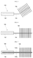
- Fig. 5 is a side view illustrating a heat dissipation means according to a second embodiment of the present invention.
- the heat dissipation fins 166 are perpendicularly coupled to the heat pipe 164.
- the number of heat dissipation fins 166 installed on the heat pipe 164 per length may be increased.
- the vertical installation according to the first embodiment allows 86 heat dissipation fins 166 to be arranged in the heat dissipation duct, while perpendicular installation relative to the heat pipe according to the second embodiment allows 100 heat dissipation fins 166 to be arranged in the heat dissipation duct.
- Fig. 6 is a side view illustrating a heat dissipation means according to a third embodiment of the present invention
- Fig. 7 is a cross-sectional view illustrating the heat dissipation means according to the third embodiment of the present invention.
- the heat pipe 164 is generally formed in the horizontal direction.
- the heat dissipation means 160 may be inconvenient if the internal space of the cabinet for electric devices is limited. In other words, the height of the device accommodation space in the cabinet may not be sufficient to allow the section for installation of heat dissipation fins to be arranged therethrough. In this case, the heat dissipation means 160 needs to be pushed into the device accommodation space from one side of the heat dissipation duct, and installation of the heat dissipation means may not be easy.
- the heat pipe 164 is generally arranged in a horizontal direction. Thereby, the height of the section thereof for installation of the heat dissipation fins is reduced.
- a wick 164b to return the heat exchange fluid to the heat sink 162 is preferably provided in the heat pipe 164 as shown in Fig. 7 .
- the heat pipe 164 according to the third environment is charged with a heat transfer fluid in the closed pipe body 164a thereof, and is provided with the wick 164b having a capillary structure enabling circulation of the heat transfer fluid.
- the heat transfer fluid returns from a part of the wick 164b on the side of the heat dissipation fins 166 to a part of the wick 164b on the side of the heat sink 162 according to a capillary phenomenon. Thereby, the heat transfer fluid may circulate, and heat of the heat sink 162 may be transferred to the heat dissipation fins 166.
- Fig. 8 is a side view illustrating a heat dissipation means according to a fourth embodiment of the present invention.
- the heat dissipation fins 166 are arranged inclined with respect to the heat pipe 164 to reduce the height of the section in which the heat dissipation fins 166 are installed.
- the heat dissipation fins 166 are connected to the heat pipe 164 in a manner that the heat dissipation fins 166 are inclined with respect to the heat pipe 164, the surfaces of contact between the heat dissipation fins 166 and the heat pipe 164 have an elliptical shape and thus the contact area thereof may increase, thereby improving heat transfer efficiency as described above in the first embodiment.
- the heat dissipation fins 166 are arranged inclined with respect to the heat pipe 164, the overall height of the heat dissipation means 160 may be reduced. Thereby, even if the internal space of the cabinet for electric devices is limited, the heat dissipation means 160 may be easily installed.
Landscapes
- Engineering & Computer Science (AREA)
- Microelectronics & Electronic Packaging (AREA)
- Physics & Mathematics (AREA)
- Thermal Sciences (AREA)
- Cooling Or The Like Of Electrical Apparatus (AREA)
- Cooling Or The Like Of Semiconductors Or Solid State Devices (AREA)
- Inverter Devices (AREA)
Applications Claiming Priority (1)
| Application Number | Priority Date | Filing Date | Title |
|---|---|---|---|
| KR1020150072890A KR20160139094A (ko) | 2015-05-26 | 2015-05-26 | 히트파이프를 구비한 전력전자 기기용 밀폐형 외함 |
Publications (1)
| Publication Number | Publication Date |
|---|---|
| EP3099152A1 true EP3099152A1 (de) | 2016-11-30 |
Family
ID=55970863
Family Applications (1)
| Application Number | Title | Priority Date | Filing Date |
|---|---|---|---|
| EP16169359.3A Withdrawn EP3099152A1 (de) | 2015-05-26 | 2016-05-12 | Geschlossener schrank für elektrische vorrichtung mit wärmerohr |
Country Status (5)
| Country | Link |
|---|---|
| US (1) | US20160353606A1 (de) |
| EP (1) | EP3099152A1 (de) |
| JP (1) | JP2016225621A (de) |
| KR (1) | KR20160139094A (de) |
| CN (1) | CN106211707A (de) |
Cited By (1)
| Publication number | Priority date | Publication date | Assignee | Title |
|---|---|---|---|---|
| CN112492405A (zh) * | 2020-12-16 | 2021-03-12 | 沈阳工程学院 | 一种用于提高交换机散热效率的交换机柜 |
Families Citing this family (19)
| Publication number | Priority date | Publication date | Assignee | Title |
|---|---|---|---|---|
| WO2015016808A1 (en) * | 2013-07-29 | 2015-02-05 | Ge Intelligent Platforms, Inc. | Heatspreader with extended surface for heat transfer through a sealed chassis wall |
| JP2017005010A (ja) * | 2015-06-05 | 2017-01-05 | 富士通株式会社 | 電子機器 |
| KR101922991B1 (ko) * | 2016-12-23 | 2018-11-28 | 효성중공업 주식회사 | 전력변환장치용 전력소자 냉각장치 |
| US10925181B2 (en) * | 2017-03-21 | 2021-02-16 | Lg Innotek Co., Ltd. | Converter |
| RU2694815C2 (ru) * | 2017-07-21 | 2019-07-17 | Общество с ограниченной ответственностью "МИП "Термодевайс" | Шкаф с радиоэлектронной аппаратурой |
| US10670650B2 (en) * | 2017-09-28 | 2020-06-02 | Advantest Corporation | Device testing with heat pipe cooling assembly |
| KR102349144B1 (ko) * | 2018-02-08 | 2022-01-10 | 동우 화인켐 주식회사 | 착색 감광성 수지 조성물, 이를 사용하여 제조된 컬러필터, 및 상기 컬러필터를 포함하는 표시장치 |
| CN108449919A (zh) * | 2018-04-02 | 2018-08-24 | 陈建明 | 一种降尘散热的通信机箱 |
| KR102092830B1 (ko) | 2018-11-02 | 2020-03-24 | 한국로봇융합연구원 | 밀폐공간에서 내부열 배출을 위한 방열장치를 구비한 방수 가능 전자장치용 하우징 및 그 하우징을 이용한 방열방법 |
| KR102135773B1 (ko) * | 2018-12-06 | 2020-07-20 | 효성중공업 주식회사 | 송전시스템의 서브모듈 냉각장치 |
| JP6813197B2 (ja) * | 2019-04-26 | 2021-01-13 | Necプラットフォームズ株式会社 | 放熱構造体 |
| CN110740622B (zh) * | 2019-07-25 | 2023-09-19 | 湖南华润电力鲤鱼江有限公司 | 一种用于电气设备的智能散热器 |
| CN110582189B (zh) * | 2019-10-15 | 2024-05-21 | 南京工业大学 | 一种应用热管作为导热元件的热管式温度控制机柜 |
| CN114007372A (zh) * | 2020-07-28 | 2022-02-01 | 华为技术有限公司 | 一种散热机柜及通信设备 |
| FR3117286A1 (fr) * | 2020-12-07 | 2022-06-10 | Sas | Système électronique et convertisseur de tension comprenant un tel système électronique |
| CN112770609A (zh) * | 2021-01-11 | 2021-05-07 | 林晓玲 | 一种智能楼宇控制柜 |
| CN114006293B (zh) * | 2021-12-30 | 2022-03-04 | 山东万海电气科技有限公司 | 一种地埋排热除植式低压开关柜 |
| CN114362486A (zh) * | 2022-02-18 | 2022-04-15 | 青岛鼎信通讯股份有限公司 | 一种应用于电力电子变压器的热管散热的级联模组单元 |
| DE102022107292A1 (de) * | 2022-03-28 | 2023-09-28 | Yazaki Systems Technologies Gmbh | Selbsttätig gezielt wärmeabführende Einheit mit einer Funktionseinrichtung |
Citations (7)
| Publication number | Priority date | Publication date | Assignee | Title |
|---|---|---|---|---|
| US5925929A (en) * | 1992-07-03 | 1999-07-20 | Hitachi, Ltd. | Cooling apparatus for electronic elements |
| JP2001024122A (ja) * | 1999-07-09 | 2001-01-26 | Mitsubishi Electric Corp | 発熱体の冷却装置 |
| JP2006306399A (ja) * | 2006-07-18 | 2006-11-09 | Toshiba Corp | 鉄道車両用電力変換装置 |
| JP2009302112A (ja) * | 2008-06-10 | 2009-12-24 | Nikon Corp | 電子機器収容ラック |
| EP2290681A2 (de) * | 2009-08-27 | 2011-03-02 | Hitachi, Ltd. | Leistungswandlungsvorrichtung |
| US20120014063A1 (en) * | 2010-07-16 | 2012-01-19 | Rockwell Automation Technologies, Inc. | Heat sink cooling arrangement for multiple power electronic circuits |
| US20150021000A1 (en) * | 2013-07-16 | 2015-01-22 | Lsis Co., Ltd. | Cabinet for power electronic apparatus |
Family Cites Families (13)
| Publication number | Priority date | Publication date | Assignee | Title |
|---|---|---|---|---|
| US2620171A (en) * | 1949-10-27 | 1952-12-02 | Slant Fin Radiator Corp | Heat exchange fin and assembly |
| JPS6112246U (ja) * | 1984-06-27 | 1986-01-24 | 株式会社日立製作所 | 冷却構造 |
| US6308771B1 (en) * | 1998-10-29 | 2001-10-30 | Advanced Thermal Solutions, Inc. | High performance fan tail heat exchanger |
| JP2000161880A (ja) * | 1998-11-26 | 2000-06-16 | Toshiba Corp | ヒートパイプ式冷却器 |
| KR200185419Y1 (ko) * | 2000-01-25 | 2000-06-15 | 주식회사에치에프알 | 무선통신 시스템의 함체 구조 |
| US20090151899A1 (en) * | 2007-12-17 | 2009-06-18 | Cheng-Yi Chang | Cooling apparatus |
| TWM353311U (en) * | 2008-10-07 | 2009-03-21 | Shi-Ming Chen | Improved heat dissipator |
| TWM403012U (en) * | 2010-11-03 | 2011-05-01 | Enermax Tech Corporation | Heat dissipating device having swirl generator |
| JP5772315B2 (ja) * | 2011-07-08 | 2015-09-02 | 富士通株式会社 | 電子機器の冷却システム |
| US20130020367A1 (en) * | 2011-07-21 | 2013-01-24 | Joel Buckley | Golf ball marker holder and method |
| JP5872913B2 (ja) * | 2012-01-20 | 2016-03-01 | 株式会社日立製作所 | 鉄道車両用電力変換装置の冷却器 |
| BR112015014943A2 (pt) * | 2012-12-27 | 2017-07-11 | Furukawa Electric Co Ltd | aparelho de resfriamento |
| US20140290929A1 (en) * | 2013-03-26 | 2014-10-02 | Ge Energy Power Conversion Technology Ltd | Heat pipe heat sink with heating unit |
-
2015
- 2015-05-26 KR KR1020150072890A patent/KR20160139094A/ko not_active Withdrawn
-
2016
- 2016-05-12 EP EP16169359.3A patent/EP3099152A1/de not_active Withdrawn
- 2016-05-25 JP JP2016103836A patent/JP2016225621A/ja active Pending
- 2016-05-25 US US15/164,196 patent/US20160353606A1/en not_active Abandoned
- 2016-05-26 CN CN201610356712.6A patent/CN106211707A/zh active Pending
Patent Citations (7)
| Publication number | Priority date | Publication date | Assignee | Title |
|---|---|---|---|---|
| US5925929A (en) * | 1992-07-03 | 1999-07-20 | Hitachi, Ltd. | Cooling apparatus for electronic elements |
| JP2001024122A (ja) * | 1999-07-09 | 2001-01-26 | Mitsubishi Electric Corp | 発熱体の冷却装置 |
| JP2006306399A (ja) * | 2006-07-18 | 2006-11-09 | Toshiba Corp | 鉄道車両用電力変換装置 |
| JP2009302112A (ja) * | 2008-06-10 | 2009-12-24 | Nikon Corp | 電子機器収容ラック |
| EP2290681A2 (de) * | 2009-08-27 | 2011-03-02 | Hitachi, Ltd. | Leistungswandlungsvorrichtung |
| US20120014063A1 (en) * | 2010-07-16 | 2012-01-19 | Rockwell Automation Technologies, Inc. | Heat sink cooling arrangement for multiple power electronic circuits |
| US20150021000A1 (en) * | 2013-07-16 | 2015-01-22 | Lsis Co., Ltd. | Cabinet for power electronic apparatus |
Cited By (1)
| Publication number | Priority date | Publication date | Assignee | Title |
|---|---|---|---|---|
| CN112492405A (zh) * | 2020-12-16 | 2021-03-12 | 沈阳工程学院 | 一种用于提高交换机散热效率的交换机柜 |
Also Published As
| Publication number | Publication date |
|---|---|
| US20160353606A1 (en) | 2016-12-01 |
| CN106211707A (zh) | 2016-12-07 |
| JP2016225621A (ja) | 2016-12-28 |
| KR20160139094A (ko) | 2016-12-07 |
Similar Documents
| Publication | Publication Date | Title |
|---|---|---|
| EP3099152A1 (de) | Geschlossener schrank für elektrische vorrichtung mit wärmerohr | |
| US11116106B2 (en) | Cooling device, cooling system, and method of cooling | |
| ES2960739T3 (es) | Estructura de disipación de calor para carcasa | |
| CN105932538B (zh) | 具备具有散热翅片的l字状热传导部件的空冷式激光装置 | |
| CN103931279B (zh) | 冷却机架式服务器的冷却装置和具备该冷却装置的数据中心 | |
| CN105932539B (zh) | 具备具有散热翅片的导热部件的空冷式激光装置 | |
| EP2827691B1 (de) | Gehäuse für leistungselektronische Vorrichtung | |
| KR101609253B1 (ko) | 반도체 모듈의 소켓 장치 | |
| CN101416373B (zh) | 电力变换装置 | |
| EP2434542A2 (de) | Wärmeableitungsvorrichtung mit mehreren wärmeleitenden Rohren | |
| JP4720688B2 (ja) | 電子制御装置の冷却装置 | |
| CN109690763B (zh) | 具有封闭壳体和冷却装置的开关柜 | |
| US7278468B2 (en) | Heat sink with multiple coolant inlets | |
| JP2015194985A (ja) | 冷却装置を備えた電子装置の構造箱 | |
| WO2015128951A1 (ja) | 半導体素子冷却装置および電子機器 | |
| JP6501510B2 (ja) | 盤用電子除湿器 | |
| US12621954B2 (en) | Electronic device | |
| US20240164045A1 (en) | Electronic device | |
| KR20060005848A (ko) | 공기조화기의 실외기 | |
| KR200426534Y1 (ko) | 용접기 내부 디바이스의 냉각구조 | |
| CN221979407U (zh) | 盒体及电源装置 | |
| CN211828748U (zh) | 一种新型网络通信设备散热装置 | |
| KR20250045407A (ko) | 내진형 통신장비 함체 | |
| KR101475455B1 (ko) | 방열구조를 갖는 전자장치, 그의 방열방법 및 방열 구조를 갖는 컴퓨터 | |
| WO2023048027A1 (ja) | 制御装置 |
Legal Events
| Date | Code | Title | Description |
|---|---|---|---|
| PUAI | Public reference made under article 153(3) epc to a published international application that has entered the european phase |
Free format text: ORIGINAL CODE: 0009012 |
|
| AK | Designated contracting states |
Kind code of ref document: A1 Designated state(s): AL AT BE BG CH CY CZ DE DK EE ES FI FR GB GR HR HU IE IS IT LI LT LU LV MC MK MT NL NO PL PT RO RS SE SI SK SM TR |
|
| AX | Request for extension of the european patent |
Extension state: BA ME |
|
| STAA | Information on the status of an ep patent application or granted ep patent |
Free format text: STATUS: REQUEST FOR EXAMINATION WAS MADE |
|
| 17P | Request for examination filed |
Effective date: 20170530 |
|
| RBV | Designated contracting states (corrected) |
Designated state(s): AL AT BE BG CH CY CZ DE DK EE ES FI FR GB GR HR HU IE IS IT LI LT LU LV MC MK MT NL NO PL PT RO RS SE SI SK SM TR |
|
| STAA | Information on the status of an ep patent application or granted ep patent |
Free format text: STATUS: EXAMINATION IS IN PROGRESS |
|
| 17Q | First examination report despatched |
Effective date: 20180925 |
|
| STAA | Information on the status of an ep patent application or granted ep patent |
Free format text: STATUS: THE APPLICATION IS DEEMED TO BE WITHDRAWN |
|
| 18D | Application deemed to be withdrawn |
Effective date: 20190206 |