EP3099559B1 - Brancard avant d'un véhicule automobile et procédé de fabrication d'un tel brancard. - Google Patents
Brancard avant d'un véhicule automobile et procédé de fabrication d'un tel brancard. Download PDFInfo
- Publication number
- EP3099559B1 EP3099559B1 EP15702524.8A EP15702524A EP3099559B1 EP 3099559 B1 EP3099559 B1 EP 3099559B1 EP 15702524 A EP15702524 A EP 15702524A EP 3099559 B1 EP3099559 B1 EP 3099559B1
- Authority
- EP
- European Patent Office
- Prior art keywords
- deformation
- shaft
- level
- deformation zone
- stretcher
- Prior art date
- Legal status (The legal status is an assumption and is not a legal conclusion. Google has not performed a legal analysis and makes no representation as to the accuracy of the status listed.)
- Active
Links
- 238000004519 manufacturing process Methods 0.000 title claims description 8
- 238000004080 punching Methods 0.000 claims description 6
- 238000000034 method Methods 0.000 claims description 3
- 230000006835 compression Effects 0.000 claims 1
- 238000007906 compression Methods 0.000 claims 1
- 230000035939 shock Effects 0.000 description 5
- 238000003466 welding Methods 0.000 description 3
- 238000010521 absorption reaction Methods 0.000 description 2
- 238000004049 embossing Methods 0.000 description 2
- 239000002184 metal Substances 0.000 description 2
- 229910000831 Steel Inorganic materials 0.000 description 1
- 239000010959 steel Substances 0.000 description 1
Images

Classifications
-
- B—PERFORMING OPERATIONS; TRANSPORTING
- B62—LAND VEHICLES FOR TRAVELLING OTHERWISE THAN ON RAILS
- B62D—MOTOR VEHICLES; TRAILERS
- B62D25/00—Superstructure or monocoque structure sub-units; Parts or details thereof not otherwise provided for
- B62D25/08—Front or rear portions
- B62D25/082—Engine compartments
-
- B—PERFORMING OPERATIONS; TRANSPORTING
- B62—LAND VEHICLES FOR TRAVELLING OTHERWISE THAN ON RAILS
- B62D—MOTOR VEHICLES; TRAILERS
- B62D21/00—Understructures, i.e. chassis frame on which a vehicle body may be mounted
- B62D21/15—Understructures, i.e. chassis frame on which a vehicle body may be mounted having impact absorbing means, e.g. a frame designed to permanently or temporarily change shape or dimension upon impact with another body
- B62D21/152—Front or rear frames
Definitions
- the present invention relates to a front stretcher of a motor vehicle and to a method of manufacturing this stretcher.
- the invention belongs to the field of devices for absorbing shocks in the front of motor vehicles.
- a motor vehicle usually has, in front of its cabin, a powertrain for propulsion and two front stretchers.
- Stretchers generally consist of a metal beam disposed along a longitudinal axis of the vehicle, on either side of the powertrain. Stretchers protect the occupants of the vehicle during a frontal collision of the vehicle with an obstacle, avoiding the intrusion of the powertrain into the passenger compartment of the vehicle.
- Document is known FR-A-2,375,500 a shock absorption device disposed on the front portion of a motor vehicle, for absorbing, by plastic deformation, the energy of an impact with an obstacle.
- Such a device is designed to deform with a predefined level of effort, depending for example on the mass of the vehicle. It is therefore necessary to design different absorption devices depending on the mass of the vehicle, which is not economical.
- the invention aims to overcome the disadvantages of the prior art.
- the present invention provides a front stretcher according to claim 1.
- the invention makes it possible to economically adjust the level of effort with which the stretcher deforms during an impact.
- the stretcher is of tubular general shape.
- the stretcher has a rectangular general section.
- the stretcher has a reduced section at the location of the first and second deformation zones.
- the stretcher comprises a main axis of deformation and the first cut has a larger dimension in an axis perpendicular to this main axis of deformation.
- the first blank is obtained by punching.
- the stretcher comprises at least a third deformation zone, provided with a second cutout positioned facing the first cut defined above.
- the subject of the invention is also a method of manufacturing a stretcher as described above, comprising a step consisting in embossing the second deformation zone described above so that it deforms with a first level of effort in the event of shock, this method being remarkable in that it further comprises a step consisting in producing on the second deformation zone at least a first cut of determined dimensions so that it deforms with a second level of lower stress at the first level of effort.
- the invention also relates to a motor vehicle comprising a stretcher as briefly described above.
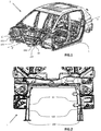
- the motor vehicle 1 represented on the figure 1 comprises two stretchers 10 arranged in front of a passenger compartment 5.
- Each stretcher 10 comprises a beam 100, generally metal, for example steel, having two ends and a plate 150.
- the beam 100 is preferably of generally tubular shape and is bonded, generally by welding, to the passenger compartment 5.
- the plate 150 is connected to the end of the beam 100 opposite to the passenger compartment 5. The plate 150 makes it possible to fix stretcher 10 of the vehicle elements 1 not shown on the figure 1 .
- the beam 100 consists of a sheet of thickness between 1.45 and 1.75 mm.
- the figure 2 has an enlarged view, from above, of the front part of the vehicle 1.
- the stretchers 10 are arranged parallel to the longitudinal axis XX 'of the vehicle 1, on either side of a central zone in which is generally disposed a power train (not shown).
- the figure 3 is a side view of a stretcher 10 according to the invention.
- the beam 100 is provided with first deformation zones 105 and a second deformation zone 110.
- the first and second deformation zones 105 and 110 are stampings made on the beam 100 to promote the compressive deformation of the stretcher 10, during an impact along a main axis of deformation AD.
- the first deformation zones 105 are arranged to deform with a first determined level of effort E1.
- the stretcher 10 has a reduced section at the location of the deformation zones 105 and 110.
- the first deformation zones 105 are for example arranged so that the first level of effort E1 is equal to 160 kN.
- the second deformation zone 110 further comprises a cutout 115 of length d1 and width d2.
- the dimensions d1 and d2 are defined so that, in the event of an impact along the main axis of deformation AD, the second deformation zone 110 deforms with a determined second level of effort E2, lower than the first level of effort E1.
- the length d1 of the blank 115 is between 20 and 70 mm and the width d2 is between 10 and 30 mm.
- the second level of effort E2 can in this case be between 110 and 140 kN, lower than the level of effort E1.
- the cutout 115 is for example made by punching the stretcher 10.
- the second deformation zone 110 may comprise several cutouts 115.
- the beam 100 comprises only a second deformation zone 110 provided with a cut-out 115.
- the beam 100 may comprise several second deformation zones 110 each comprising one or more cut-outs 115.
- a third deformation zone 120 (visible on the figure 5 ), similar to the second deformation zone 110, may be provided with a cutout 125, positioned facing the cutout 115 of the second deformation zone 110.
- FIGS. 4 and 5 have views of a stretcher before 10, during steps of the manufacturing process of this stretcher 10.
- the method comprises a stamping step, the result of which is visible on the figure 4 , making it possible to obtain embossings at the level of the first deformation zones 105 and the second deformation zone 110 of the stretcher 10.
- the stampings made on the first deformation zones 105 and on the second deformation zone 110 are arranged so that they deform, in case of shock, with a first level of effort E1.
- a cutout 115 is made on the second deformation zone 110 of length d1 and width d2.
- the dimensions d1 and d2 of the cutout 115 are determined so that the second deformation zone 110 deforms, in the event of an impact, with a second level of effort E2, which is less than the first level of effort E1.
- Another cutout 125 can also be made on a third deformation zone 120, facing the cutout 115 of the second deformation zone 110.
- the punching step may for example be performed simultaneously with the stamping step, before a welding operation of the stretcher 10 On the vehicle 1. Alternatively, the punching step can be performed after this welding operation.
- a front stretcher of a vehicle according to the invention and a method of manufacturing such a stretcher can adjust economically the level of effort with which the stretcher is deformed.
Landscapes
- Engineering & Computer Science (AREA)
- Chemical & Material Sciences (AREA)
- Combustion & Propulsion (AREA)
- Transportation (AREA)
- Mechanical Engineering (AREA)
- Body Structure For Vehicles (AREA)
Description
- La présente invention se rapporte à un brancard avant d'un véhicule automobile ainsi qu'à un procédé de fabrication de ce brancard.
- L'invention appartient au domaine des dispositifs pour absorber les chocs à l'avant des véhicules automobiles.
- Un véhicule automobile comporte habituellement, en avant de son habitacle, un groupe motopropulseur permettant sa propulsion et deux brancards avant. Les brancards sont généralement constitués d'une poutre métallique disposée selon un axe longitudinal du véhicule, de part et d'autre du groupe motopropulseur. Les brancards permettent de protéger les occupants du véhicule lors d'un choc frontal du véhicule avec un obstacle, en évitant l'intrusion du groupe motopropulseur dans l'habitacle du véhicule.
- Lors d'un tel choc, pour la protection des occupants de l'habitacle du véhicule, il est également nécessaire que certains éléments absorbent une partie de l'énergie cinétique du véhicule et de l'obstacle percuté.
- On connaît du document
FR-A-2 375 500 - Un tel dispositif est conçu pour se déformer avec un niveau d'effort prédéfini, fonction par exemple de la masse du véhicule. Il est par conséquent nécessaire de concevoir des dispositifs d'absorption différents en fonction de la masse du véhicule, ce qui n'est pas économique.
- L'invention a pour but de remédier aux inconvénients de l'art antérieur.
- Dans ce but, la présente invention propose un brancard avant selon la revendication 1.
- Ainsi, l'invention permet d'ajuster de manière économique le niveau d'effort avec lequel le brancard se déforme lors d'un choc.
- Selon une caractéristique particulière, le brancard est de forme générale tubulaire.
- Selon une caractéristique particulière, le brancard présente une section générale rectangulaire.
- Selon une caractéristique particulière, le brancard présente une section réduite à l'endroit des première et deuxième zones de déformation.
- Selon une caractéristique particulière, le brancard comporte un axe principal de déformation et la première découpe comporte une plus grande dimension dans un axe perpendiculaire à cet axe principal de déformation.
- Selon une caractéristique particulière, la première découpe est obtenue par poinçonnage.
- Selon une caractéristique particulière, le brancard comporte au moins une troisième zone de déformation, munie d'une deuxième découpe positionnée en regard de la première découpe définie plus haut.
- L'invention à également pour objet un procédé de fabrication d'un brancard tel que décrit précédemment, comportant une étape consistant à réaliser des emboutis sur la deuxième zone de déformation décrite plus haut pour qu'elle se déforme avec un premier niveau d'effort en cas de choc, ce procédé étant remarquable en ce qu'il comporte en outre une étape consistant à réaliser sur la deuxième zone de déformation au moins une première découpe de dimensions déterminées pour qu'elle se déforme avec un deuxième niveau d'effort inférieur au premier niveau d'effort.
- Dans le même but, l'invention a aussi pour objet un véhicule automobile comportant un brancard tel que brièvement décrit plus haut.
- L'invention sera mieux comprise et d'autres aspects et avantages apparaîtront plus clairement à la lecture de la description qui suit d'un mode particulier de réalisation, donné à titre d'exemple nullement limitatif et en référence aux dessins qui l'accompagnent, dans lesquels :
- la
figure 1 est une vue en perspective d'un véhicule équipé de brancards avant conformes à l'invention ; - la
figure 2 est une vue de dessus agrandie de l'avant du véhicule de lafigure 1 ; - la
figure 3 est une vue de côté d'un brancard avant conforme à l'invention ; - les
figures 4 et 5 sont des vues en perspective du brancard de lafigure 3 suivant des étapes d'un procédé de fabrication selon l'invention. - Sur les
figures 1 à 5 , les mêmes repères sont utilisés pour désigner les mêmes pièces. - Le véhicule automobile 1 représenté sur la
figure 1 comporte deux brancards 10 disposés en avant d'un habitacle 5. - Chaque brancard 10 comporte une poutre 100, généralement métallique, par exemple en acier, présentant deux extrémités et un plateau 150.
- La poutre 100 est de préférence de forme générale tubulaire et est liée, généralement par soudage, à l'habitacle 5. Le plateau 150 est lié à l'extrémité de la poutre 100 opposée à l'habitacle 5. Le plateau 150 permet de fixer au brancard 10 des éléments du véhicule 1 non illustrés sur la
figure 1 . - A titre d'exemple non limitatif, la poutre 100 est constituée d'une tôle d'épaisseur comprise entre 1,45 et 1,75 mm.
- La
figure 2 présente une vue agrandie, de dessus, de la partie avant du véhicule 1. Les brancards 10 sont disposés parallèlement à l'axe longitudinal XX' du véhicule 1, de part et d'autre d'une zone centrale dans laquelle est généralement disposé un groupe motopropulseur (non illustré). - La
figure 3 est une vue de côté d'un brancard 10 conforme à l'invention. La poutre 100 est munie de premières zones de déformation 105 et d'une deuxième zone de déformation110. - Les premières et deuxième zones de déformation 105 et 110 sont des emboutis réalisés sur la poutre 100 pour favoriser la déformation par compression du brancard 10, lors d'un choc selon un axe principal de déformation AD. De par leurs formes et leurs dimensions, en cas de choc, les premières zones de déformation 105 sont agencées pour se déformer avec un premier niveau déterminé d'effort E1. Le brancard 10 présente une section réduite à l'endroit des zones de déformation 105 et 110.
- Les premières zones de déformation 105 sont par exemple agencées pour que le premier niveau d'effort E1 soit égal à 160 kN.
- Conformément à l'invention, la deuxième zone de déformation 110 comporte en outre une découpe 115 de longueur d1 et de largeur d2. Les dimensions d1 et d2 sont définies pour que, en cas de choc selon l'axe principal de déformation AD, la deuxième zone de déformation 110 se déforme avec un deuxième niveau déterminé d'effort E2, inférieur au premier niveau d'effort E1.
- Par exemple, la longueur d1 de la découpe 115 est comprise entre 20 et 70 mm et la largeur d2 est comprise entre 10 et 30 mm. Le deuxième niveau d'effort E2 peut dans ce cas être compris entre 110 et 140 kN, inférieur au niveau d'effort E1.
- La découpe 115 est par exemple réalisée par poinçonnage du brancard 10.
- Dans une variante, non illustrée, la deuxième zone de déformation 110 peut comporter plusieurs découpes 115.
- Dans le mode de réalisation représenté sur la
figure 3 , la poutre 100 ne comporte qu'une deuxième zone de déformation 110 munie d'une découpe 115. Dans une autre variante, la poutre 100 peut comporter plusieurs deuxièmes zones de déformation 110 comportant chacune une ou plusieurs découpes 115. - Par ailleurs, une troisième zone de déformation 120 (visible sur la
figure 5 ), similaire à la deuxième zone de déformation 110, peut être munie d'une découpe 125, positionnée en regard de la découpe 115 de la deuxième zone de déformation 110. - Les
figures 4 et 5 présentent des vues d'un brancard avant 10, lors d'étapes du procédé de fabrication de ce brancard 10. - Le procédé comporte une étape d'emboutissage, dont le résultat est visible sur la
figure 4 , permettant d'obtenir des emboutis au niveau des premières zones de déformation 105 et de la deuxième zone de déformation 110 du brancard 10. Les emboutis réalisés sur les premières zones de déformation 105 et sur la deuxième zone de déformation 110 sont agencés pour qu'elles se déforment, en cas de choc, avec un premier niveau d'effort E1. - Lors d'une étape de poinçonnage, dont le résultat est visible sur la
figure 5 , une découpe 115 est réalisée sur la deuxième zone de déformation 110 de longueur d1 et de largeur d2. Les dimensions d1 et d2 de la découpe 115 sont déterminées pour que la deuxième zone de déformation 110 se déforme, en cas de choc, avec un deuxième niveau d'effort E2, inférieur au premier niveau d'effort E1. - Une autre découpe 125 peut également être réalisée sur une troisième zone de déformation 120, en regard de la découpe 115 de la deuxième zone de déformation 110.
- L'étape de poinçonnage peut par exemple être réalisée simultanément à l'étape d'emboutissage, avant une opération de soudage du brancard 10 sur le véhicule 1. En variante, l'étape de poinçonnage peut être réalisée après cette opération de soudage.
- Ainsi, un brancard avant d'un véhicule conforme à l'invention et un procédé de fabrication d'un tel brancard permettent d'ajuster de manière économique le niveau d'effort avec lequel le brancard se déforme.
Claims (9)
- Brancard avant (10) d'un véhicule automobile (1) comportant une poutre (100), comportant au moins une première zone de déformation (105) agencée pour se déformer avec un premier niveau d'effort (E1) en cas de choc et au moins une deuxième zone de déformation (110), caractérisé en ce que les premières et deuxième zones de déformation (105) et (110) sont des emboutis réalisés sur la poutre (100) pour favoriser la déformation par compression du brancard 10, la deuxième zone de déformation (110) comportant au moins une première découpe (115) de dimensions (d1, d2) déterminées afin que ladite deuxième zone de déformation (110) se déforme en cas de choc avec un deuxième niveau d'effort (E2) inférieur au premier (E1).
- Brancard (10) selon la revendication 1, caractérisé en ce qu'il est de forme générale tubulaire.
- Brancard (10) selon la revendication 2, caractérisé en ce qu'il présente une section générale rectangulaire.
- Brancard (10) selon la revendication 2 ou 3, caractérisé en ce qu'il présente une section réduite à l'endroit desdites première (105) et deuxième (110) zones de déformation.
- Brancard (10) selon l'une quelconque des revendications précédentes comportant un axe principal de déformation (AD), caractérisé en ce que ladite première découpe (115) comporte une plus grande dimension (d1) dans un axe perpendiculaire audit axe principal de déformation (AD).
- Brancard (10) selon l'une quelconque des revendications précédentes, caractérisé en ce qu'il comporte au moins une troisième zone de déformation (120) munie d'une deuxième découpe (125) positionnée en regard de ladite première découpe (115).
- Procédé de fabrication d'un brancard (10) selon l'une quelconque des revendication précédentes, comportant une étape consistant à réaliser des emboutis sur ladite deuxième zone de déformation (110) pour qu'elle se déforme avec un premier niveau d'effort (E1) en cas de choc, caractérisé en ce qu'il comporte en outre une étape consistant à réaliser sur ladite deuxième zone de déformation (110) au moins une première découpe (115) de dimensions (d1, d2) déterminées pour qu'elle se déforme avec un deuxième niveau d'effort (E2) inférieur au premier (E1).
- Procédé selon la revendication 7, caractérisé en ce que ladite première découpe (115) est obtenue par poinçonnage.
- Véhicule automobile, caractérisé en ce qu'il comporte au moins un brancard (10) selon l'une quelconque des revendications 1 à 6.
Applications Claiming Priority (2)
| Application Number | Priority Date | Filing Date | Title |
|---|---|---|---|
| FR1450737A FR3016851B1 (fr) | 2014-01-30 | 2014-01-30 | Brancard avant d'un vehicule automobile et procede de fabrication d’un tel brancard. |
| PCT/FR2015/050015 WO2015114228A1 (fr) | 2014-01-30 | 2015-01-06 | Brancard avant d'un véhicule automobile et procédé de fabrication d'un tel brancard. |
Publications (2)
| Publication Number | Publication Date |
|---|---|
| EP3099559A1 EP3099559A1 (fr) | 2016-12-07 |
| EP3099559B1 true EP3099559B1 (fr) | 2018-09-26 |
Family
ID=50729634
Family Applications (1)
| Application Number | Title | Priority Date | Filing Date |
|---|---|---|---|
| EP15702524.8A Active EP3099559B1 (fr) | 2014-01-30 | 2015-01-06 | Brancard avant d'un véhicule automobile et procédé de fabrication d'un tel brancard. |
Country Status (6)
| Country | Link |
|---|---|
| EP (1) | EP3099559B1 (fr) |
| CN (1) | CN105980241B (fr) |
| ES (1) | ES2691996T3 (fr) |
| FR (1) | FR3016851B1 (fr) |
| PT (1) | PT3099559T (fr) |
| WO (1) | WO2015114228A1 (fr) |
Families Citing this family (1)
| Publication number | Priority date | Publication date | Assignee | Title |
|---|---|---|---|---|
| FR3142163B1 (fr) | 2022-11-22 | 2024-10-04 | Psa Automobiles Sa | Brancard pour véhicule automobile comprenant un élément de renfort interne |
Citations (3)
| Publication number | Priority date | Publication date | Assignee | Title |
|---|---|---|---|---|
| JPH10244955A (ja) * | 1997-03-06 | 1998-09-14 | Toyota Motor Corp | フロントサイドメンバの衝突エネルギ吸収構造 |
| WO2009051816A2 (fr) * | 2007-10-17 | 2009-04-23 | Shape Corporation | Structure polygonale tronconique écrasable |
| US20100102592A1 (en) * | 2008-09-19 | 2010-04-29 | Tau Tyan | Twelve-Cornered Strengthening Member |
Family Cites Families (14)
| Publication number | Priority date | Publication date | Assignee | Title |
|---|---|---|---|---|
| US3508633A (en) * | 1967-05-17 | 1970-04-28 | Nissan Motor | Plastically deformable impact absorbing means for vehicles |
| US4031978A (en) * | 1975-05-28 | 1977-06-28 | Tayco Developments, Inc. | Energy absorber unit and energy management system |
| US4190276A (en) | 1976-12-22 | 1980-02-26 | Mitsubishi Jidosha Kogyo Kabushiki Kaisha | Deformable impact absorbing device for vehicles |
| JP2001270465A (ja) * | 2000-03-27 | 2001-10-02 | Fuji Heavy Ind Ltd | 車体構造 |
| WO2003042024A1 (fr) * | 2001-11-14 | 2003-05-22 | L & L Products, Inc. | Composant automobile de structure composite ayant une absorption d'energie de rupture specifique |
| US6695393B1 (en) * | 2002-09-18 | 2004-02-24 | Ford Global Technologies, Llc | Kinetic energy absorbing rail for an automotive frame |
| US7185945B2 (en) * | 2004-08-06 | 2007-03-06 | General Motors Corporation | Structural assembly for vehicles |
| US7591502B2 (en) * | 2007-01-11 | 2009-09-22 | Ford Motor Company | Tunable inner fender structure |
| CN101186218A (zh) * | 2007-09-30 | 2008-05-28 | 重庆长安汽车股份有限公司 | 汽车纵梁前段碰撞吸能结构 |
| CN101269670A (zh) * | 2007-12-28 | 2008-09-24 | 上汽通用五菱汽车股份有限公司 | 一种具有变形引导装置的车辆车架结构 |
| CN100572172C (zh) * | 2008-04-25 | 2009-12-23 | 奇瑞汽车股份有限公司 | 一种车架的前部吸能结构 |
| JP5251692B2 (ja) * | 2009-04-08 | 2013-07-31 | トヨタ自動車株式会社 | 車両用骨格部材 |
| EP2266846B1 (fr) * | 2009-06-08 | 2013-04-17 | Faurecia Exteriors GmbH | Elément d'absorption d'énergie pour systèmes de gestion de collisions sur des véhicules automobiles |
| JP5287927B2 (ja) * | 2011-05-13 | 2013-09-11 | トヨタ自動車株式会社 | 車体構造 |
-
2014
- 2014-01-30 FR FR1450737A patent/FR3016851B1/fr not_active Expired - Fee Related
-
2015
- 2015-01-06 EP EP15702524.8A patent/EP3099559B1/fr active Active
- 2015-01-06 CN CN201580006458.0A patent/CN105980241B/zh active Active
- 2015-01-06 PT PT15702524T patent/PT3099559T/pt unknown
- 2015-01-06 ES ES15702524.8T patent/ES2691996T3/es active Active
- 2015-01-06 WO PCT/FR2015/050015 patent/WO2015114228A1/fr not_active Ceased
Patent Citations (3)
| Publication number | Priority date | Publication date | Assignee | Title |
|---|---|---|---|---|
| JPH10244955A (ja) * | 1997-03-06 | 1998-09-14 | Toyota Motor Corp | フロントサイドメンバの衝突エネルギ吸収構造 |
| WO2009051816A2 (fr) * | 2007-10-17 | 2009-04-23 | Shape Corporation | Structure polygonale tronconique écrasable |
| US20100102592A1 (en) * | 2008-09-19 | 2010-04-29 | Tau Tyan | Twelve-Cornered Strengthening Member |
Also Published As
| Publication number | Publication date |
|---|---|
| FR3016851A1 (fr) | 2015-07-31 |
| WO2015114228A1 (fr) | 2015-08-06 |
| FR3016851B1 (fr) | 2016-01-22 |
| PT3099559T (pt) | 2018-11-14 |
| CN105980241A (zh) | 2016-09-28 |
| ES2691996T3 (es) | 2018-11-29 |
| CN105980241B (zh) | 2020-07-28 |
| EP3099559A1 (fr) | 2016-12-07 |
Similar Documents
| Publication | Publication Date | Title |
|---|---|---|
| EP2048407B1 (fr) | Ensemble absorbeur d'énergie amélioré pour véhicule à moteur, comprenant un tube en matière plastique forcé à travers un support de rainurage préférentiellement réalisé par emboutissage | |
| CN109803875B (zh) | 用于车辆的防撞结构 | |
| KR101134946B1 (ko) | 차량용 범퍼빔의 조립방법 | |
| FR2978410A1 (fr) | Longeron pour caisse de vehicule automobile de section transversale octogonale et vehicule equipe de tels longerons. | |
| EP3099559B1 (fr) | Brancard avant d'un véhicule automobile et procédé de fabrication d'un tel brancard. | |
| EP0713820B1 (fr) | Dispositif d'absorption d'énergie d'une colonne de direction de véhicule automobile | |
| EP2917091B1 (fr) | Traverse avant de pavillon pour véhicule automobile a déformation progressive | |
| EP2983969B1 (fr) | Deflecteur aerodynamique pour partie arriere d'un vehicule | |
| WO2025074045A1 (fr) | Vehicule automobile comprenant un systeme d'absorption de chocs a deformation programmable, et procede sur la base d'un tel vehicule | |
| EP2767458B1 (fr) | Plancher arrière de charge pour véhicule automobile, comportant un longeronnet renforcé | |
| EP4359287B1 (fr) | Ensemble de structure de face avant pour un véhicule automobile | |
| EP4284683B1 (fr) | Structure avant de véhicule automobile comportant une traverse supérieure et véhicule comportant une telle structure avant | |
| EP4355621A1 (fr) | Ensemble pour véhicule automobile comprenant une poutre de pare-chocs et deux absorbeurs | |
| EP2105375A1 (fr) | Traverse inférieure de baie perfectionnée pour protéger les occupants du véhicule en cas de choc frontal | |
| EP3210859A1 (fr) | Structure avant d'un vehicule automobile comportant une gache qui comporte une partie superieure et une partie inferieure deformable, gache correspondante et procede de fabrication d'une telle gache | |
| EP3392092B1 (fr) | Ensemble d''extremite notamment arriere d''un vehicule automobile | |
| KR102456470B1 (ko) | 차량용 범퍼 스태이 유닛 | |
| JP2005162061A (ja) | 車両用衝撃吸収部材 | |
| KR101988368B1 (ko) | 에너지 흡수 및 마찰음을 개선한 자동차용 범퍼빔 조립체 | |
| WO2011108080A1 (fr) | Structure avant de véhicule | |
| EP4570598A1 (fr) | Dispositif absorbeur de choc piéton d'un véhicule automobile | |
| EP4725807A1 (fr) | Soubassement pour véhicule automobile | |
| EP3199409B1 (fr) | Élément de moule de grille d'aération pour face avant de véhicule automobile | |
| WO2005105528A1 (fr) | Boitier de deformation pour vehicule automobile | |
| FR3017360A1 (fr) | Longeron automobile a raidisseur oblique pour deversement programme en choc mur |
Legal Events
| Date | Code | Title | Description |
|---|---|---|---|
| PUAI | Public reference made under article 153(3) epc to a published international application that has entered the european phase |
Free format text: ORIGINAL CODE: 0009012 |
|
| STAA | Information on the status of an ep patent application or granted ep patent |
Free format text: STATUS: REQUEST FOR EXAMINATION WAS MADE |
|
| 17P | Request for examination filed |
Effective date: 20160623 |
|
| AK | Designated contracting states |
Kind code of ref document: A1 Designated state(s): AL AT BE BG CH CY CZ DE DK EE ES FI FR GB GR HR HU IE IS IT LI LT LU LV MC MK MT NL NO PL PT RO RS SE SI SK SM TR |
|
| AX | Request for extension of the european patent |
Extension state: BA ME |
|
| DAX | Request for extension of the european patent (deleted) | ||
| RAP1 | Party data changed (applicant data changed or rights of an application transferred) |
Owner name: PSA AUTOMOBILES SA |
|
| STAA | Information on the status of an ep patent application or granted ep patent |
Free format text: STATUS: EXAMINATION IS IN PROGRESS |
|
| 17Q | First examination report despatched |
Effective date: 20171206 |
|
| GRAP | Despatch of communication of intention to grant a patent |
Free format text: ORIGINAL CODE: EPIDOSNIGR1 |
|
| STAA | Information on the status of an ep patent application or granted ep patent |
Free format text: STATUS: GRANT OF PATENT IS INTENDED |
|
| INTG | Intention to grant announced |
Effective date: 20180518 |
|
| GRAS | Grant fee paid |
Free format text: ORIGINAL CODE: EPIDOSNIGR3 |
|
| GRAA | (expected) grant |
Free format text: ORIGINAL CODE: 0009210 |
|
| STAA | Information on the status of an ep patent application or granted ep patent |
Free format text: STATUS: THE PATENT HAS BEEN GRANTED |
|
| AK | Designated contracting states |
Kind code of ref document: B1 Designated state(s): AL AT BE BG CH CY CZ DE DK EE ES FI FR GB GR HR HU IE IS IT LI LT LU LV MC MK MT NL NO PL PT RO RS SE SI SK SM TR |
|
| REG | Reference to a national code |
Ref country code: GB Ref legal event code: FG4D Free format text: NOT ENGLISH |
|
| REG | Reference to a national code |
Ref country code: CH Ref legal event code: EP |
|
| REG | Reference to a national code |
Ref country code: AT Ref legal event code: REF Ref document number: 1045660 Country of ref document: AT Kind code of ref document: T Effective date: 20181015 |
|
| REG | Reference to a national code |
Ref country code: IE Ref legal event code: FG4D Free format text: LANGUAGE OF EP DOCUMENT: FRENCH |
|
| REG | Reference to a national code |
Ref country code: DE Ref legal event code: R084 Ref document number: 602015016915 Country of ref document: DE |
|
| REG | Reference to a national code |
Ref country code: DE Ref legal event code: R096 Ref document number: 602015016915 Country of ref document: DE |
|
| REG | Reference to a national code |
Ref country code: PT Ref legal event code: SC4A Ref document number: 3099559 Country of ref document: PT Date of ref document: 20181114 Kind code of ref document: T Free format text: AVAILABILITY OF NATIONAL TRANSLATION Effective date: 20181025 |
|
| REG | Reference to a national code |
Ref country code: GB Ref legal event code: 746 Effective date: 20181029 |
|
| REG | Reference to a national code |
Ref country code: ES Ref legal event code: FG2A Ref document number: 2691996 Country of ref document: ES Kind code of ref document: T3 Effective date: 20181129 |
|
| REG | Reference to a national code |
Ref country code: NL Ref legal event code: MP Effective date: 20180926 |
|
| PG25 | Lapsed in a contracting state [announced via postgrant information from national office to epo] |
Ref country code: SE Free format text: LAPSE BECAUSE OF FAILURE TO SUBMIT A TRANSLATION OF THE DESCRIPTION OR TO PAY THE FEE WITHIN THE PRESCRIBED TIME-LIMIT Effective date: 20180926 Ref country code: GR Free format text: LAPSE BECAUSE OF FAILURE TO SUBMIT A TRANSLATION OF THE DESCRIPTION OR TO PAY THE FEE WITHIN THE PRESCRIBED TIME-LIMIT Effective date: 20181227 Ref country code: BG Free format text: LAPSE BECAUSE OF FAILURE TO SUBMIT A TRANSLATION OF THE DESCRIPTION OR TO PAY THE FEE WITHIN THE PRESCRIBED TIME-LIMIT Effective date: 20181226 Ref country code: LT Free format text: LAPSE BECAUSE OF FAILURE TO SUBMIT A TRANSLATION OF THE DESCRIPTION OR TO PAY THE FEE WITHIN THE PRESCRIBED TIME-LIMIT Effective date: 20180926 Ref country code: FI Free format text: LAPSE BECAUSE OF FAILURE TO SUBMIT A TRANSLATION OF THE DESCRIPTION OR TO PAY THE FEE WITHIN THE PRESCRIBED TIME-LIMIT Effective date: 20180926 Ref country code: RS Free format text: LAPSE BECAUSE OF FAILURE TO SUBMIT A TRANSLATION OF THE DESCRIPTION OR TO PAY THE FEE WITHIN THE PRESCRIBED TIME-LIMIT Effective date: 20180926 Ref country code: NO Free format text: LAPSE BECAUSE OF FAILURE TO SUBMIT A TRANSLATION OF THE DESCRIPTION OR TO PAY THE FEE WITHIN THE PRESCRIBED TIME-LIMIT Effective date: 20181226 |
|
| REG | Reference to a national code |
Ref country code: LT Ref legal event code: MG4D |
|
| PG25 | Lapsed in a contracting state [announced via postgrant information from national office to epo] |
Ref country code: LV Free format text: LAPSE BECAUSE OF FAILURE TO SUBMIT A TRANSLATION OF THE DESCRIPTION OR TO PAY THE FEE WITHIN THE PRESCRIBED TIME-LIMIT Effective date: 20180926 Ref country code: HR Free format text: LAPSE BECAUSE OF FAILURE TO SUBMIT A TRANSLATION OF THE DESCRIPTION OR TO PAY THE FEE WITHIN THE PRESCRIBED TIME-LIMIT Effective date: 20180926 Ref country code: AL Free format text: LAPSE BECAUSE OF FAILURE TO SUBMIT A TRANSLATION OF THE DESCRIPTION OR TO PAY THE FEE WITHIN THE PRESCRIBED TIME-LIMIT Effective date: 20180926 |
|
| REG | Reference to a national code |
Ref country code: AT Ref legal event code: MK05 Ref document number: 1045660 Country of ref document: AT Kind code of ref document: T Effective date: 20180926 |
|
| PG25 | Lapsed in a contracting state [announced via postgrant information from national office to epo] |
Ref country code: RO Free format text: LAPSE BECAUSE OF FAILURE TO SUBMIT A TRANSLATION OF THE DESCRIPTION OR TO PAY THE FEE WITHIN THE PRESCRIBED TIME-LIMIT Effective date: 20180926 Ref country code: CZ Free format text: LAPSE BECAUSE OF FAILURE TO SUBMIT A TRANSLATION OF THE DESCRIPTION OR TO PAY THE FEE WITHIN THE PRESCRIBED TIME-LIMIT Effective date: 20180926 Ref country code: EE Free format text: LAPSE BECAUSE OF FAILURE TO SUBMIT A TRANSLATION OF THE DESCRIPTION OR TO PAY THE FEE WITHIN THE PRESCRIBED TIME-LIMIT Effective date: 20180926 Ref country code: AT Free format text: LAPSE BECAUSE OF FAILURE TO SUBMIT A TRANSLATION OF THE DESCRIPTION OR TO PAY THE FEE WITHIN THE PRESCRIBED TIME-LIMIT Effective date: 20180926 Ref country code: NL Free format text: LAPSE BECAUSE OF FAILURE TO SUBMIT A TRANSLATION OF THE DESCRIPTION OR TO PAY THE FEE WITHIN THE PRESCRIBED TIME-LIMIT Effective date: 20180926 Ref country code: PL Free format text: LAPSE BECAUSE OF FAILURE TO SUBMIT A TRANSLATION OF THE DESCRIPTION OR TO PAY THE FEE WITHIN THE PRESCRIBED TIME-LIMIT Effective date: 20180926 Ref country code: IS Free format text: LAPSE BECAUSE OF FAILURE TO SUBMIT A TRANSLATION OF THE DESCRIPTION OR TO PAY THE FEE WITHIN THE PRESCRIBED TIME-LIMIT Effective date: 20190126 |
|
| PG25 | Lapsed in a contracting state [announced via postgrant information from national office to epo] |
Ref country code: SK Free format text: LAPSE BECAUSE OF FAILURE TO SUBMIT A TRANSLATION OF THE DESCRIPTION OR TO PAY THE FEE WITHIN THE PRESCRIBED TIME-LIMIT Effective date: 20180926 Ref country code: SM Free format text: LAPSE BECAUSE OF FAILURE TO SUBMIT A TRANSLATION OF THE DESCRIPTION OR TO PAY THE FEE WITHIN THE PRESCRIBED TIME-LIMIT Effective date: 20180926 |
|
| REG | Reference to a national code |
Ref country code: DE Ref legal event code: R097 Ref document number: 602015016915 Country of ref document: DE |
|
| PG25 | Lapsed in a contracting state [announced via postgrant information from national office to epo] |
Ref country code: DK Free format text: LAPSE BECAUSE OF FAILURE TO SUBMIT A TRANSLATION OF THE DESCRIPTION OR TO PAY THE FEE WITHIN THE PRESCRIBED TIME-LIMIT Effective date: 20180926 |
|
| PLBE | No opposition filed within time limit |
Free format text: ORIGINAL CODE: 0009261 |
|
| STAA | Information on the status of an ep patent application or granted ep patent |
Free format text: STATUS: NO OPPOSITION FILED WITHIN TIME LIMIT |
|
| PG25 | Lapsed in a contracting state [announced via postgrant information from national office to epo] |
Ref country code: MC Free format text: LAPSE BECAUSE OF FAILURE TO SUBMIT A TRANSLATION OF THE DESCRIPTION OR TO PAY THE FEE WITHIN THE PRESCRIBED TIME-LIMIT Effective date: 20180926 |
|
| REG | Reference to a national code |
Ref country code: CH Ref legal event code: PL |
|
| 26N | No opposition filed |
Effective date: 20190627 |
|
| PG25 | Lapsed in a contracting state [announced via postgrant information from national office to epo] |
Ref country code: LU Free format text: LAPSE BECAUSE OF NON-PAYMENT OF DUE FEES Effective date: 20190106 |
|
| REG | Reference to a national code |
Ref country code: BE Ref legal event code: MM Effective date: 20190131 |
|
| REG | Reference to a national code |
Ref country code: IE Ref legal event code: MM4A |
|
| PG25 | Lapsed in a contracting state [announced via postgrant information from national office to epo] |
Ref country code: SI Free format text: LAPSE BECAUSE OF FAILURE TO SUBMIT A TRANSLATION OF THE DESCRIPTION OR TO PAY THE FEE WITHIN THE PRESCRIBED TIME-LIMIT Effective date: 20180926 |
|
| PG25 | Lapsed in a contracting state [announced via postgrant information from national office to epo] |
Ref country code: BE Free format text: LAPSE BECAUSE OF NON-PAYMENT OF DUE FEES Effective date: 20190131 |
|
| PG25 | Lapsed in a contracting state [announced via postgrant information from national office to epo] |
Ref country code: CH Free format text: LAPSE BECAUSE OF NON-PAYMENT OF DUE FEES Effective date: 20190131 Ref country code: LI Free format text: LAPSE BECAUSE OF NON-PAYMENT OF DUE FEES Effective date: 20190131 |
|
| PG25 | Lapsed in a contracting state [announced via postgrant information from national office to epo] |
Ref country code: IE Free format text: LAPSE BECAUSE OF NON-PAYMENT OF DUE FEES Effective date: 20190106 |
|
| PG25 | Lapsed in a contracting state [announced via postgrant information from national office to epo] |
Ref country code: TR Free format text: LAPSE BECAUSE OF FAILURE TO SUBMIT A TRANSLATION OF THE DESCRIPTION OR TO PAY THE FEE WITHIN THE PRESCRIBED TIME-LIMIT Effective date: 20180926 |
|
| PG25 | Lapsed in a contracting state [announced via postgrant information from national office to epo] |
Ref country code: MT Free format text: LAPSE BECAUSE OF FAILURE TO SUBMIT A TRANSLATION OF THE DESCRIPTION OR TO PAY THE FEE WITHIN THE PRESCRIBED TIME-LIMIT Effective date: 20180926 |
|
| PG25 | Lapsed in a contracting state [announced via postgrant information from national office to epo] |
Ref country code: CY Free format text: LAPSE BECAUSE OF FAILURE TO SUBMIT A TRANSLATION OF THE DESCRIPTION OR TO PAY THE FEE WITHIN THE PRESCRIBED TIME-LIMIT Effective date: 20180926 |
|
| PG25 | Lapsed in a contracting state [announced via postgrant information from national office to epo] |
Ref country code: HU Free format text: LAPSE BECAUSE OF FAILURE TO SUBMIT A TRANSLATION OF THE DESCRIPTION OR TO PAY THE FEE WITHIN THE PRESCRIBED TIME-LIMIT; INVALID AB INITIO Effective date: 20150106 |
|
| PG25 | Lapsed in a contracting state [announced via postgrant information from national office to epo] |
Ref country code: MK Free format text: LAPSE BECAUSE OF FAILURE TO SUBMIT A TRANSLATION OF THE DESCRIPTION OR TO PAY THE FEE WITHIN THE PRESCRIBED TIME-LIMIT Effective date: 20180926 |
|
| REG | Reference to a national code |
Ref country code: DE Ref legal event code: R081 Ref document number: 602015016915 Country of ref document: DE Owner name: STELLANTIS AUTO SAS, FR Free format text: FORMER OWNER: PSA AUTOMOBILES SA, POISSY, FR |
|
| PGFP | Annual fee paid to national office [announced via postgrant information from national office to epo] |
Ref country code: PT Payment date: 20241218 Year of fee payment: 11 |
|
| PGFP | Annual fee paid to national office [announced via postgrant information from national office to epo] |
Ref country code: GB Payment date: 20241219 Year of fee payment: 11 |
|
| PGFP | Annual fee paid to national office [announced via postgrant information from national office to epo] |
Ref country code: FR Payment date: 20241219 Year of fee payment: 11 |
|
| PGFP | Annual fee paid to national office [announced via postgrant information from national office to epo] |
Ref country code: DE Payment date: 20241218 Year of fee payment: 11 |
|
| PGFP | Annual fee paid to national office [announced via postgrant information from national office to epo] |
Ref country code: ES Payment date: 20250203 Year of fee payment: 11 |
|
| PGFP | Annual fee paid to national office [announced via postgrant information from national office to epo] |
Ref country code: IT Payment date: 20250107 Year of fee payment: 11 |