EP3099577B1 - Verbessertes betankungssystem für ein raumfahrzeug - Google Patents
Verbessertes betankungssystem für ein raumfahrzeug Download PDFInfo
- Publication number
- EP3099577B1 EP3099577B1 EP15704063.5A EP15704063A EP3099577B1 EP 3099577 B1 EP3099577 B1 EP 3099577B1 EP 15704063 A EP15704063 A EP 15704063A EP 3099577 B1 EP3099577 B1 EP 3099577B1
- Authority
- EP
- European Patent Office
- Prior art keywords
- actuator
- valve
- tank
- feed
- configuration
- Prior art date
- Legal status (The legal status is an assumption and is not a legal conclusion. Google has not performed a legal analysis and makes no representation as to the accuracy of the status listed.)
- Active
Links
Images
Classifications
-
- B—PERFORMING OPERATIONS; TRANSPORTING
- B64—AIRCRAFT; AVIATION; COSMONAUTICS
- B64G—COSMONAUTICS; VEHICLES OR EQUIPMENT THEREFOR
- B64G5/00—Ground equipment for vehicles, e.g. starting towers, fuelling arrangements
-
- B—PERFORMING OPERATIONS; TRANSPORTING
- B64—AIRCRAFT; AVIATION; COSMONAUTICS
- B64G—COSMONAUTICS; VEHICLES OR EQUIPMENT THEREFOR
- B64G1/00—Cosmonautic vehicles
- B64G1/22—Parts of, or equipment specially adapted for fitting in or to, cosmonautic vehicles
- B64G1/40—Arrangements or adaptations of propulsion systems
- B64G1/402—Propellant tanks; Feeding propellants
-
- F—MECHANICAL ENGINEERING; LIGHTING; HEATING; WEAPONS; BLASTING
- F02—COMBUSTION ENGINES; HOT-GAS OR COMBUSTION-PRODUCT ENGINE PLANTS
- F02K—JET-PROPULSION PLANTS
- F02K9/00—Rocket-engine plants, i.e. plants carrying both fuel and oxidant therefor; Control thereof
- F02K9/42—Rocket-engine plants, i.e. plants carrying both fuel and oxidant therefor; Control thereof using liquid or gaseous propellants
- F02K9/60—Constructional parts; Details not otherwise provided for
- F02K9/605—Reservoirs
-
- F—MECHANICAL ENGINEERING; LIGHTING; HEATING; WEAPONS; BLASTING
- F05—INDEXING SCHEMES RELATING TO ENGINES OR PUMPS IN VARIOUS SUBCLASSES OF CLASSES F01-F04
- F05D—INDEXING SCHEME FOR ASPECTS RELATING TO NON-POSITIVE-DISPLACEMENT MACHINES OR ENGINES, GAS-TURBINES OR JET-PROPULSION PLANTS
- F05D2220/00—Application
- F05D2220/80—Application in supersonic vehicles excluding hypersonic vehicles or ram, scram or rocket propulsion
Definitions
- the present invention relates to the field of propellant refueling systems of a spacecraft, and finds an application particularly for cryogenic or non-cryogenic thrusters of a launcher.
- Propellant refueling of a spacecraft such as a rocket must be performed as close as possible to takeoff, in order to minimize the storage time of the propellant in the rocket tanks.
- the existing devices for propellant feed tanks of a spacecraft cf. FR 2 943 626 , create significant pressure drops, which significantly reduce the filling rate of the tanks and considerably lengthen the filling time, thereby increasing the storage time of the propellant in the tanks of the spacecraft.
- cryogenic propellant makes problematic the use of certain technologies, in particular the use of electromagnetic actuators, which are not compatible with such temperatures, for example of the order of -253 ° C.
- the actuator is typically coupled to an elastic return means exerting a thrust force on the actuator tending to move it to the open configuration in which the actuator opens the valve.
- the system then advantageously comprises a control, for example pneumatic, adapted to exert a force on the actuator opposing the thrust force applied by the elastic return means, so as to tend to move the actuator to the configuration closed.
- the actuator can be coupled to an elastic return means exerting a thrust force on the actuator tending to move it to the closed configuration in which the actuator closes the valve.
- the system then advantageously comprises a control, for example pneumatic, adapted to exert a force on the actuator opposing the thrust force applied by the elastic return means, so as to tend to move the actuator to the configuration opened.
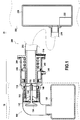
- the figure 1 represents a propellant feed system according to one aspect of the invention in a feed configuration.
- This figure shows an edge edge 10 and a ground side 20, respectively corresponding to equipment on board a spacecraft, and equipment mounted on the ground.
- the power system shown on the figure 1 thus includes edge-side equipment 10, and ground-side equipment 20.
- the valve 134 is arranged in such a way that, depending on its displacement in the valve guide 130, it closes off the supply orifice 112 or not.
- a guide element 140 is advantageously positioned between the valve guide 130 and the frame 110.
- the valve guide 130 is coupled to a thrust means 160 adapted to, in the absence of application of additional forces, exert a thrust force on the valve guide 130 so as to maintain the valve 134 in the position of closing the supply port 112.
- the free end 212 of the supply duct 210 is arranged opposite the supply orifice 112 of the frame 110.
- the actuator 250 is thus also arranged facing the supply port 112 of the frame 110.
- the actuator 250 is configured so that when the edge device 100 and the ground device 200 are so associated, the end free 252 of the actuator 250 comes into contact with the movable element 130, preferably substantially at the outer periphery of the moving element 130.
- the actuator 250 can thus control the displacement of the valve 130, and thus the opening or not of the supply orifice 112, for example by moving the valve guide 130 so that the valve 134 closes or not channels arranged in the vicinity of the supply port 112.
- the elastic return means 260 as shown exerts a thrust force on the actuator 250 tending to move the valve guide 130 so that the valve 134 opens the supply port 112 and thus allow the fluid passage of the conduit supply 210 to the tank edge 120.
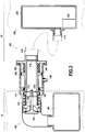
- control pressure via the control orifice 245 makes it possible to drive the actuator 250 so as to reduce or even cancel the thrust force that it exerts as the valve 130; the valve 130 is then returned to a closed configuration by the thrust means 160, in which the valve 134 closes the supply port 112, as shown in FIG. figure 2 .
- the control of the opening or the closing of the supply orifice 112 can thus be carried out by means of a pressure control applied via the control orifice 245.
- the actuator 250 undergoes a thrust force exerted by the elastic return means 260 tending to open the supply port 112; here, therefore, control of the opening of the feed orifice 112 is carried out.
- An inverted configuration can also be carried out, in which the closure of the supply orifice 112 is controlled.
- the elastic return means is then configured so as to exert a force tending to move the actuator 250 so as to cancel or at least minimize the force it applies to the valve guide 130, the valve 134 thus closing the supply port 112 in the absence of pressure applied via the control port 245.
- the supply duct 210 is connected to the ground tank 220, which is associated with a transfer system 222 typically comprising a pump, configured so as to make it possible to transfer fluid, such as propellant, from the ground tank 220 to the ground.
- a transfer system 222 typically comprising a pump, configured so as to make it possible to transfer fluid, such as propellant, from the ground tank 220 to the ground.
- tank edge 120 through the supply duct 210 and the supply port 112.
- a shutter 214 is also positioned near the free end 212 of the supply duct 210, adapted to, in a shutter configuration, close the supply duct 210, and in a supply configuration, allow a transfer of fluid from the ground tank 220 to the tank edge 120.
- the shutter 214 is shown in the feed configuration on the figure 1 and in shutter configuration on the figure 2 .
- An initial configuration is considered in which the edge device 100 and the ground device 200 are joined.
- the shutter 214 is closed, as well as the valve 134.
- the tank edge 120 and the tank 220 are thus isolated from one another.
- the edge device 100 and the ground device 200 are associated, as shown in FIG. figure 1 .
- the inlet orifice 112 is opened by the actuator 250.
- the shutter 214 is open, and the transfer system 222 is operated so as to fill the tank edge 120 with fluid contained in the ground tank 220. Once the tank edge 120 filled to the desired level, the filling ceases.
- the actuator 250 is controlled so as to no longer exert an opening force on the valve guide 130 of the valve 134, the valve body 134 thus closing the supply orifice 112 so that the tank edge 120 is isolated from the supply duct 210.
- the transfer system 222 stops sending fluid from the ground tank 220 to the supply duct 210.
- the supply duct 210 is then filled with fluid.
- the supply pipe 210 is drained so as to purge the fluid therein, and then the shutter 214 is closed.
- the emptying of the supply duct is typically carried out by means of a drainage system, which may, for example, put the supply duct 210 under pressure. Sealing tests can then be carried out in the supply duct 210, making it possible in particular to check the tightness of the valve 134.
- the spacecraft can take off, the edge device 100 and the ground device 200 are then separated.
- the positioning of the actuator 250 on the outer periphery of the supply duct 210 and not within the supply duct 210 makes it possible to limit the presence of components arranged in the supply duct 210, and therefore to limit Disturbances of the fluid flow in the feed pipe 210.
- the pressure losses are thus limited, the flow rate can be increased and thus the filling of the edge tank 120 can be accelerated for a reduced edge edge valve diameter 134.
- the positioning of the actuator 250 at the outer periphery of the supply condition 210 and the offset to the outside of the ducts of the control elements of the actuator 250 also makes it possible to have a supply duct aligned with the orifice supply 112, which is advantageous in terms of reduction of pressure drops.
- the proposed actuator structure 250 and actuator control system is also compatible with cryogenic propellants such as commonly used for spacecraft that reach temperatures of the order of -253 ° C, and are therefore incompatible with certain types of actuators such as magnetic actuators.
- ground device 200 presented can be used without requiring structural modifications at the edge device 100. Only the dimensions of the supply duct 210 and the actuator 250 play a role in the actuation of the valve 134. The proposed ground device 200 can thus be associated with existing edge devices 100.
Landscapes
- Engineering & Computer Science (AREA)
- Aviation & Aerospace Engineering (AREA)
- Remote Sensing (AREA)
- Chemical & Material Sciences (AREA)
- Combustion & Propulsion (AREA)
- General Physics & Mathematics (AREA)
- Astronomy & Astrophysics (AREA)
- Physics & Mathematics (AREA)
- Mechanical Engineering (AREA)
- General Engineering & Computer Science (AREA)
- Filling Or Discharging Of Gas Storage Vessels (AREA)
- Loading And Unloading Of Fuel Tanks Or Ships (AREA)
- Fluid-Driven Valves (AREA)
- Fluid-Pressure Circuits (AREA)
Claims (9)
- System zur Versorgung eines Raumfahrzeugs mit Treibstoff für ein Raumfahrzeug, umfassend- eine bordseitige Vorrichtung (100), umfassend• ein Gestell (110) mit einer Zuführöffnung (112), die zu einem bordseitigen Tank (120) führt,• ein Ventil (134), das dazu ausgelegt ist, die Zuführöffnung (112) wahlweise abzudichten oder zu öffnen,- eine bodenseitige Vorrichtung (200), umfassendwobei die bordseitige Vorrichtung (100) und die bodenseitige Vorrichtung (200) so konfiguriert sind, dass sie miteinander kombiniert werden können, um in offener Konfiguration den Transfer von Treibstoff aus der Zuführleitung (210) in den bordseitigen Tank (120) zu ermöglichen und in geschlossener Konfiguration den bordseitigen Tank (120) von der Zuführleitung (210) zu isolieren, wobei der Stellantrieb (250) dazu ausgelegt ist, das Öffnen und Schließen der Zuführöffnung (112) durch das Ventil (134) zu steuern,• eine Zuführleitung (210) mit offenem Ende (212),• einem Ventilkörper (240) mit einem Stellantrieb (250),
wobei das System dadurch gekennzeichnet ist, dass der Ventilkörper (240) das offene Ende (212) der Zuführleitung (210) umgibt und der Stellantrieb (250) den äußeren Umfang der Zuführleitung (210) umgibt. - System gemäß Anspruch 1, wobei die bodenseitige Vorrichtung einen Aufbau zum Starten (230) umfasst, der einen bodenseitigen Tank (220) aufweist, an den die Zuführleitung (210) angeschlossen ist, wobei das System ferner einen Verschluss (214) umfasst, der dazu ausgelegt ist,- in einer Versorgungskonfiguration den Transfer von Treibstoff zwischen dem bodenseitigen Tank (220) und dem bordseitigen Tank (120) ermöglichen,- und in einer Verschlusskonfiguration den bordseitigen Tank (120) von dem bodenseitigen Tank (220) zu isolieren.
- System gemäß Anspruch 2, wobei der Aufbau zum Starten ferner ein Abführsystem umfasst, das dazu ausgelegt ist, eine Reinigung der Zuführleitung (210) durchzuführen, derart dass bei der Anwendung einer Steuerung das Transfersystem den in der Zuführleitung (210) enthaltenen Treibstoff ansaugt und in einem Grundtank speichert.
- System gemäß einem der Ansprüche 2 oder 3, ferner umfassend Leckdetektionsmittel, die dazu ausgelegt sind, in der Zuführleitung (210) Dichtigkeitstests durchzuführen, wenn das Ventil (134) die Zuführöffnung (112) abdichtet.
- System gemäß einem der Ansprüche 1 bis 4, wobei der Stellantrieb (250) mit einem elastischen Rückstellmittel (260) gekoppelt ist, das eine Schubkraft auf den Stellantrieb (250) ausübt, um ihn in eine offene Konfiguration zu bewegen, in der der Stellantrieb (250) das Ventil (134) öffnet.
- System gemäß Anspruch 5, umfassend eine Steuerung (245), die dazu ausgelegt ist, eine Kraft auf den Stellantrieb (250) auszuüben, die dem Schub entgegengesetzt ist, der durch das elastische Rückstellmittel (260) ausgeübt wird, sodass der Stellantrieb in Richtung der geschlossenen Konfiguration bewegt wird.
- System gemäß einem der Ansprüche 1 bis 4, wobei der Stellantrieb (250) mit einem elastischen Rückstellmittel (260) gekoppelt ist, das eine Schubkraft auf den Stellantrieb (250) ausübt, um ihn in die geschlossene Konfiguration zu bewegen, in der der Stellantrieb (250) das Ventil (134) schließt, sodass das Ventil (134) die Zuführöffnung (112) abdichtet.
- System gemäß Anspruch 7, umfassend eine Steuerung (245), die dazu ausgelegt ist, eine Kraft auf den Stellantrieb (250) auszuüben, die dem Schub entgegengesetzt ist, der durch das elastische Rückstellmittel (260) ausgeübt wird, sodass der Stellantrieb (250) in Richtung der offenen Konfiguration bewegt wird, in der das Ventil (134) die Zuführöffnung (112) nicht abdichtet.
- System gemäß einem der Ansprüche 6 oder 8, wobei die Steuerung (245) eine pneumatische Steuerung ist.
Applications Claiming Priority (2)
| Application Number | Priority Date | Filing Date | Title |
|---|---|---|---|
| FR1400227A FR3016865B1 (fr) | 2014-01-29 | 2014-01-29 | Systeme d'alimentation ameliore en ergol pour un vehicule spatial |
| PCT/FR2015/050157 WO2015114238A1 (fr) | 2014-01-29 | 2015-01-22 | Système d'alimentation amélioré en ergol pour un véhicule spatial |
Publications (2)
| Publication Number | Publication Date |
|---|---|
| EP3099577A1 EP3099577A1 (de) | 2016-12-07 |
| EP3099577B1 true EP3099577B1 (de) | 2018-05-16 |
Family
ID=51292996
Family Applications (1)
| Application Number | Title | Priority Date | Filing Date |
|---|---|---|---|
| EP15704063.5A Active EP3099577B1 (de) | 2014-01-29 | 2015-01-22 | Verbessertes betankungssystem für ein raumfahrzeug |
Country Status (6)
| Country | Link |
|---|---|
| US (1) | US10308376B2 (de) |
| EP (1) | EP3099577B1 (de) |
| JP (1) | JP6529978B2 (de) |
| FR (1) | FR3016865B1 (de) |
| RU (1) | RU2667020C2 (de) |
| WO (1) | WO2015114238A1 (de) |
Cited By (1)
| Publication number | Priority date | Publication date | Assignee | Title |
|---|---|---|---|---|
| CN110406700A (zh) * | 2019-07-02 | 2019-11-05 | 蓝箭航天空间科技股份有限公司 | 一种用于火箭储箱推进剂加注的低温连接器 |
Families Citing this family (3)
| Publication number | Priority date | Publication date | Assignee | Title |
|---|---|---|---|---|
| CN109896049B (zh) * | 2018-11-22 | 2021-06-18 | 北京航天发射技术研究所 | 一种直角坐标柔性非接触式连接器自动对接装置及方法 |
| US11958640B2 (en) | 2020-12-28 | 2024-04-16 | Sener Aeroespacial, S.A. | Connection system and connecting method for transferring fluids between two vehicles or between a vehicle and a fixed structure |
| CN117869122B (zh) * | 2024-03-11 | 2024-06-14 | 江苏深蓝航天有限公司 | 一种推进剂控制装置 |
Family Cites Families (19)
| Publication number | Priority date | Publication date | Assignee | Title |
|---|---|---|---|---|
| US4609169A (en) * | 1984-08-14 | 1986-09-02 | The United States Of America As Represented By The Secretary Of The Air Force | Propellant tank resupply system |
| JP3176955B2 (ja) | 1990-06-19 | 2001-06-18 | 株式会社東芝 | 冷媒用弁装置 |
| US5404923A (en) * | 1993-05-26 | 1995-04-11 | Rockwell International Corporation | Apparatus for automated fueling of a launch vehicle |
| US5582366A (en) * | 1995-01-19 | 1996-12-10 | Motorola, Inc. | Satellite fueling system and method therefor |
| US5904302A (en) * | 1997-03-21 | 1999-05-18 | Brown; Albert W. | Aircraft fueling nozzle |
| JPH11230402A (ja) | 1998-02-13 | 1999-08-27 | Asahi Organic Chem Ind Co Ltd | 排出弁 |
| US6125871A (en) * | 1999-01-22 | 2000-10-03 | Ashland, Inc. | Valve assembly with flush and sample capability |
| US6142194A (en) * | 1999-03-09 | 2000-11-07 | Cla-Val | Pressure fuel servicing nozzle |
| JP2002005378A (ja) * | 2000-06-23 | 2002-01-09 | Ishikawajima Harima Heavy Ind Co Ltd | 極低温配管の結合装置 |
| RU2225813C2 (ru) * | 2002-02-04 | 2004-03-20 | Открытое акционерное общество "Ракетно-космическая корпорация "Энергия" им. С.П.Королева" | Способ заправки жидким кислородом бака окислителя ракетной двигательной установки |
| FR2849144B1 (fr) * | 2002-12-18 | 2005-10-21 | Snecma Moteurs | Dispositif de vanne cryogenique a actionneur pneumatique |
| JP5078219B2 (ja) * | 2004-04-26 | 2012-11-21 | 三菱重工業株式会社 | 接続具、流体供給システム、接続具接続方法、及び接続具分離方法 |
| US7575200B2 (en) * | 2005-09-07 | 2009-08-18 | The Boeing Company | Space depot for spacecraft resupply |
| US8074935B2 (en) * | 2007-03-09 | 2011-12-13 | Macdonald Dettwiler & Associates Inc. | Satellite refuelling system and method |
| FR2943626B1 (fr) * | 2009-03-30 | 2011-04-22 | Snecma | Dispositif d'avitaillement de propulseurs d'un lanceur |
| US8820353B2 (en) * | 2010-06-30 | 2014-09-02 | Carleton Technologies, Inc. | Interface assembly for space vehicles |
| WO2013082719A1 (en) * | 2011-12-05 | 2013-06-13 | Macdonald Dettwiler & Associates Inc. | System and tool for accessing satellite fill/drain valves during propellant resupply |
| US9231323B1 (en) * | 2014-07-28 | 2016-01-05 | NovaWurks, Inc. | Spacecraft docking connector |
| FR3029173B1 (fr) * | 2014-11-28 | 2018-03-23 | Arianegroup Sas | Dispositif et procede de deverrouillage d'un dispositif d'avitaillement |
-
2014
- 2014-01-29 FR FR1400227A patent/FR3016865B1/fr active Active
-
2015
- 2015-01-22 US US15/114,228 patent/US10308376B2/en active Active
- 2015-01-22 WO PCT/FR2015/050157 patent/WO2015114238A1/fr not_active Ceased
- 2015-01-22 RU RU2016135001A patent/RU2667020C2/ru active
- 2015-01-22 JP JP2016549503A patent/JP6529978B2/ja active Active
- 2015-01-22 EP EP15704063.5A patent/EP3099577B1/de active Active
Non-Patent Citations (1)
| Title |
|---|
| None * |
Cited By (1)
| Publication number | Priority date | Publication date | Assignee | Title |
|---|---|---|---|---|
| CN110406700A (zh) * | 2019-07-02 | 2019-11-05 | 蓝箭航天空间科技股份有限公司 | 一种用于火箭储箱推进剂加注的低温连接器 |
Also Published As
| Publication number | Publication date |
|---|---|
| US20170008649A1 (en) | 2017-01-12 |
| JP6529978B2 (ja) | 2019-06-12 |
| RU2016135001A (ru) | 2018-03-05 |
| JP2017504538A (ja) | 2017-02-09 |
| FR3016865A1 (fr) | 2015-07-31 |
| EP3099577A1 (de) | 2016-12-07 |
| FR3016865B1 (fr) | 2016-02-19 |
| RU2016135001A3 (de) | 2018-07-11 |
| RU2667020C2 (ru) | 2018-09-13 |
| US10308376B2 (en) | 2019-06-04 |
| WO2015114238A1 (fr) | 2015-08-06 |
Similar Documents
| Publication | Publication Date | Title |
|---|---|---|
| EP2414242B1 (de) | Betankungsvorrichtung für trägerraketenantrieb | |
| WO2015114238A1 (fr) | Système d'alimentation amélioré en ergol pour un véhicule spatial | |
| EP3436706B1 (de) | Sichereitsblock mit doppeltem ventil für einen hydraulischen zylinder | |
| WO1998020260A2 (fr) | Dispositif de maintien en position de la tige d'un verin hydraulique | |
| WO2018019801A1 (fr) | Régulateur de débit de ventilation pour un réservoir pressurisé de véhicule | |
| EP2778364A1 (de) | Steuervorrichtung der Einspeisung einer Flüssigkeit in ein System | |
| FR2794101A1 (fr) | Actionneur pneumatique | |
| JP2012521927A5 (de) | ||
| EP3578871B1 (de) | Vorrichtung zur versorgung mit fluid unter druck | |
| FR2991750A1 (fr) | Dispositif de controle pour bouteille de fluide sous pression et bouteille correspondante | |
| EP3925893A1 (de) | Verfahren zur druckentlastung einer flugzeugkabine am boden von ausserhalb des flugzeugs | |
| EP4455021B1 (de) | Flugzeug mit mindestens einer wasserstoffversorgungsvorrichtung mit mindestens einem gasabführungssystem im falle eines lecks | |
| EP3098403B1 (de) | Vorrichtung zur steuerung der zufuhr einer unter druck stehenden flüssigkeit | |
| EP2901057B1 (de) | Entlüftungsventil für flüssigkeitstank mit überdruckschutzsicherheitsmerkmal | |
| CA2719464A1 (fr) | Dispositif receveur de gaz sous pression, ensemble distributeur-dispositif receveur, et systeme d'alimentation correspondant | |
| FR2976064A1 (fr) | Engin sous-marin comportant des moyens de lancement d'un vehicule sous-marin | |
| FR2976065A1 (fr) | Engin sous-marin comportant des moyens de lancement d'un vehicule sous-marin en auto-demarrage | |
| EP0597768A1 (de) | Sicherheitssystem für ein mit gasförmigen Brennstoff arbeitendes Strassenfahrzeug | |
| CA3079703C (fr) | Aeronef muni d'un systeme de ravitaillement de carburant en vol | |
| EP4296168A1 (de) | Tanksystem mit einem ventil in form eines pendelsystems | |
| EP0494818A1 (de) | Fernbedienbare Fülleinrichtung eines Ölbehälters | |
| EP3775645B1 (de) | Verbessertes regelventil mit integrierter spülfunktion | |
| EP3393965B1 (de) | Ausrüstung mit einem einsetzbaren koaxialventil zur übertragung eines fluid in ein reservoir und verfahren | |
| FR3003839A1 (fr) | Engin sous-marin comportant au moins un tube externe de reception et de lancement d'un vehicule sous-marin | |
| FR3035922A1 (fr) | Dispositif d'inversion de poussee pour un turboreacteur d'aeronef, et nacelle comportant le dispositif |
Legal Events
| Date | Code | Title | Description |
|---|---|---|---|
| PUAI | Public reference made under article 153(3) epc to a published international application that has entered the european phase |
Free format text: ORIGINAL CODE: 0009012 |
|
| STAA | Information on the status of an ep patent application or granted ep patent |
Free format text: STATUS: REQUEST FOR EXAMINATION WAS MADE |
|
| 17P | Request for examination filed |
Effective date: 20160826 |
|
| AK | Designated contracting states |
Kind code of ref document: A1 Designated state(s): AL AT BE BG CH CY CZ DE DK EE ES FI FR GB GR HR HU IE IS IT LI LT LU LV MC MK MT NL NO PL PT RO RS SE SI SK SM TR |
|
| AX | Request for extension of the european patent |
Extension state: BA ME |
|
| DAX | Request for extension of the european patent (deleted) | ||
| REG | Reference to a national code |
Ref country code: DE Ref legal event code: R079 Ref document number: 602015011144 Country of ref document: DE Free format text: PREVIOUS MAIN CLASS: B64G0005000000 Ipc: F02K0009600000 |
|
| GRAP | Despatch of communication of intention to grant a patent |
Free format text: ORIGINAL CODE: EPIDOSNIGR1 |
|
| STAA | Information on the status of an ep patent application or granted ep patent |
Free format text: STATUS: GRANT OF PATENT IS INTENDED |
|
| RIC1 | Information provided on ipc code assigned before grant |
Ipc: B64G 5/00 20060101ALI20170531BHEP Ipc: F02K 9/60 20060101AFI20170531BHEP |
|
| INTG | Intention to grant announced |
Effective date: 20170626 |
|
| GRAJ | Information related to disapproval of communication of intention to grant by the applicant or resumption of examination proceedings by the epo deleted |
Free format text: ORIGINAL CODE: EPIDOSDIGR1 |
|
| STAA | Information on the status of an ep patent application or granted ep patent |
Free format text: STATUS: REQUEST FOR EXAMINATION WAS MADE |
|
| GRAP | Despatch of communication of intention to grant a patent |
Free format text: ORIGINAL CODE: EPIDOSNIGR1 |
|
| STAA | Information on the status of an ep patent application or granted ep patent |
Free format text: STATUS: GRANT OF PATENT IS INTENDED |
|
| INTC | Intention to grant announced (deleted) | ||
| INTG | Intention to grant announced |
Effective date: 20171128 |
|
| GRAS | Grant fee paid |
Free format text: ORIGINAL CODE: EPIDOSNIGR3 |
|
| GRAA | (expected) grant |
Free format text: ORIGINAL CODE: 0009210 |
|
| STAA | Information on the status of an ep patent application or granted ep patent |
Free format text: STATUS: THE PATENT HAS BEEN GRANTED |
|
| AK | Designated contracting states |
Kind code of ref document: B1 Designated state(s): AL AT BE BG CH CY CZ DE DK EE ES FI FR GB GR HR HU IE IS IT LI LT LU LV MC MK MT NL NO PL PT RO RS SE SI SK SM TR |
|
| REG | Reference to a national code |
Ref country code: GB Ref legal event code: FG4D Free format text: NOT ENGLISH |
|
| REG | Reference to a national code |
Ref country code: CH Ref legal event code: EP |
|
| REG | Reference to a national code |
Ref country code: IE Ref legal event code: FG4D Free format text: LANGUAGE OF EP DOCUMENT: FRENCH |
|
| REG | Reference to a national code |
Ref country code: DE Ref legal event code: R096 Ref document number: 602015011144 Country of ref document: DE |
|
| REG | Reference to a national code |
Ref country code: AT Ref legal event code: REF Ref document number: 999814 Country of ref document: AT Kind code of ref document: T Effective date: 20180615 |
|
| REG | Reference to a national code |
Ref country code: SE Ref legal event code: TRGR |
|
| REG | Reference to a national code |
Ref country code: NL Ref legal event code: MP Effective date: 20180516 |
|
| REG | Reference to a national code |
Ref country code: LT Ref legal event code: MG4D |
|
| PG25 | Lapsed in a contracting state [announced via postgrant information from national office to epo] |
Ref country code: FI Free format text: LAPSE BECAUSE OF FAILURE TO SUBMIT A TRANSLATION OF THE DESCRIPTION OR TO PAY THE FEE WITHIN THE PRESCRIBED TIME-LIMIT Effective date: 20180516 Ref country code: NO Free format text: LAPSE BECAUSE OF FAILURE TO SUBMIT A TRANSLATION OF THE DESCRIPTION OR TO PAY THE FEE WITHIN THE PRESCRIBED TIME-LIMIT Effective date: 20180816 Ref country code: BG Free format text: LAPSE BECAUSE OF FAILURE TO SUBMIT A TRANSLATION OF THE DESCRIPTION OR TO PAY THE FEE WITHIN THE PRESCRIBED TIME-LIMIT Effective date: 20180816 Ref country code: ES Free format text: LAPSE BECAUSE OF FAILURE TO SUBMIT A TRANSLATION OF THE DESCRIPTION OR TO PAY THE FEE WITHIN THE PRESCRIBED TIME-LIMIT Effective date: 20180516 Ref country code: LT Free format text: LAPSE BECAUSE OF FAILURE TO SUBMIT A TRANSLATION OF THE DESCRIPTION OR TO PAY THE FEE WITHIN THE PRESCRIBED TIME-LIMIT Effective date: 20180516 |
|
| RAP2 | Party data changed (patent owner data changed or rights of a patent transferred) |
Owner name: CENTRE NATIONAL D'ETUDES SPATIALES |
|
| PG25 | Lapsed in a contracting state [announced via postgrant information from national office to epo] |
Ref country code: LV Free format text: LAPSE BECAUSE OF FAILURE TO SUBMIT A TRANSLATION OF THE DESCRIPTION OR TO PAY THE FEE WITHIN THE PRESCRIBED TIME-LIMIT Effective date: 20180516 Ref country code: HR Free format text: LAPSE BECAUSE OF FAILURE TO SUBMIT A TRANSLATION OF THE DESCRIPTION OR TO PAY THE FEE WITHIN THE PRESCRIBED TIME-LIMIT Effective date: 20180516 Ref country code: NL Free format text: LAPSE BECAUSE OF FAILURE TO SUBMIT A TRANSLATION OF THE DESCRIPTION OR TO PAY THE FEE WITHIN THE PRESCRIBED TIME-LIMIT Effective date: 20180516 Ref country code: GR Free format text: LAPSE BECAUSE OF FAILURE TO SUBMIT A TRANSLATION OF THE DESCRIPTION OR TO PAY THE FEE WITHIN THE PRESCRIBED TIME-LIMIT Effective date: 20180817 Ref country code: RS Free format text: LAPSE BECAUSE OF FAILURE TO SUBMIT A TRANSLATION OF THE DESCRIPTION OR TO PAY THE FEE WITHIN THE PRESCRIBED TIME-LIMIT Effective date: 20180516 |
|
| RAP2 | Party data changed (patent owner data changed or rights of a patent transferred) |
Owner name: CENTRE NATIONAL D'ETUDES SPATIALES Owner name: SAFRAN AIRCRAFT ENGINES |
|
| REG | Reference to a national code |
Ref country code: AT Ref legal event code: MK05 Ref document number: 999814 Country of ref document: AT Kind code of ref document: T Effective date: 20180516 |
|
| PG25 | Lapsed in a contracting state [announced via postgrant information from national office to epo] |
Ref country code: PL Free format text: LAPSE BECAUSE OF FAILURE TO SUBMIT A TRANSLATION OF THE DESCRIPTION OR TO PAY THE FEE WITHIN THE PRESCRIBED TIME-LIMIT Effective date: 20180516 Ref country code: EE Free format text: LAPSE BECAUSE OF FAILURE TO SUBMIT A TRANSLATION OF THE DESCRIPTION OR TO PAY THE FEE WITHIN THE PRESCRIBED TIME-LIMIT Effective date: 20180516 Ref country code: DK Free format text: LAPSE BECAUSE OF FAILURE TO SUBMIT A TRANSLATION OF THE DESCRIPTION OR TO PAY THE FEE WITHIN THE PRESCRIBED TIME-LIMIT Effective date: 20180516 Ref country code: RO Free format text: LAPSE BECAUSE OF FAILURE TO SUBMIT A TRANSLATION OF THE DESCRIPTION OR TO PAY THE FEE WITHIN THE PRESCRIBED TIME-LIMIT Effective date: 20180516 Ref country code: AT Free format text: LAPSE BECAUSE OF FAILURE TO SUBMIT A TRANSLATION OF THE DESCRIPTION OR TO PAY THE FEE WITHIN THE PRESCRIBED TIME-LIMIT Effective date: 20180516 Ref country code: CZ Free format text: LAPSE BECAUSE OF FAILURE TO SUBMIT A TRANSLATION OF THE DESCRIPTION OR TO PAY THE FEE WITHIN THE PRESCRIBED TIME-LIMIT Effective date: 20180516 Ref country code: SK Free format text: LAPSE BECAUSE OF FAILURE TO SUBMIT A TRANSLATION OF THE DESCRIPTION OR TO PAY THE FEE WITHIN THE PRESCRIBED TIME-LIMIT Effective date: 20180516 |
|
| REG | Reference to a national code |
Ref country code: DE Ref legal event code: R097 Ref document number: 602015011144 Country of ref document: DE |
|
| PG25 | Lapsed in a contracting state [announced via postgrant information from national office to epo] |
Ref country code: SM Free format text: LAPSE BECAUSE OF FAILURE TO SUBMIT A TRANSLATION OF THE DESCRIPTION OR TO PAY THE FEE WITHIN THE PRESCRIBED TIME-LIMIT Effective date: 20180516 |
|
| PLBE | No opposition filed within time limit |
Free format text: ORIGINAL CODE: 0009261 |
|
| STAA | Information on the status of an ep patent application or granted ep patent |
Free format text: STATUS: NO OPPOSITION FILED WITHIN TIME LIMIT |
|
| 26N | No opposition filed |
Effective date: 20190219 |
|
| PG25 | Lapsed in a contracting state [announced via postgrant information from national office to epo] |
Ref country code: SI Free format text: LAPSE BECAUSE OF FAILURE TO SUBMIT A TRANSLATION OF THE DESCRIPTION OR TO PAY THE FEE WITHIN THE PRESCRIBED TIME-LIMIT Effective date: 20180516 |
|
| PG25 | Lapsed in a contracting state [announced via postgrant information from national office to epo] |
Ref country code: MC Free format text: LAPSE BECAUSE OF FAILURE TO SUBMIT A TRANSLATION OF THE DESCRIPTION OR TO PAY THE FEE WITHIN THE PRESCRIBED TIME-LIMIT Effective date: 20180516 |
|
| REG | Reference to a national code |
Ref country code: CH Ref legal event code: PL |
|
| PG25 | Lapsed in a contracting state [announced via postgrant information from national office to epo] |
Ref country code: LU Free format text: LAPSE BECAUSE OF NON-PAYMENT OF DUE FEES Effective date: 20190122 |
|
| REG | Reference to a national code |
Ref country code: BE Ref legal event code: MM Effective date: 20190131 |
|
| REG | Reference to a national code |
Ref country code: IE Ref legal event code: MM4A |
|
| PG25 | Lapsed in a contracting state [announced via postgrant information from national office to epo] |
Ref country code: AL Free format text: LAPSE BECAUSE OF FAILURE TO SUBMIT A TRANSLATION OF THE DESCRIPTION OR TO PAY THE FEE WITHIN THE PRESCRIBED TIME-LIMIT Effective date: 20180516 Ref country code: BE Free format text: LAPSE BECAUSE OF NON-PAYMENT OF DUE FEES Effective date: 20190131 |
|
| PG25 | Lapsed in a contracting state [announced via postgrant information from national office to epo] |
Ref country code: CH Free format text: LAPSE BECAUSE OF NON-PAYMENT OF DUE FEES Effective date: 20190131 Ref country code: LI Free format text: LAPSE BECAUSE OF NON-PAYMENT OF DUE FEES Effective date: 20190131 |
|
| PG25 | Lapsed in a contracting state [announced via postgrant information from national office to epo] |
Ref country code: IE Free format text: LAPSE BECAUSE OF NON-PAYMENT OF DUE FEES Effective date: 20190122 |
|
| PG25 | Lapsed in a contracting state [announced via postgrant information from national office to epo] |
Ref country code: TR Free format text: LAPSE BECAUSE OF FAILURE TO SUBMIT A TRANSLATION OF THE DESCRIPTION OR TO PAY THE FEE WITHIN THE PRESCRIBED TIME-LIMIT Effective date: 20180516 |
|
| PG25 | Lapsed in a contracting state [announced via postgrant information from national office to epo] |
Ref country code: PT Free format text: LAPSE BECAUSE OF FAILURE TO SUBMIT A TRANSLATION OF THE DESCRIPTION OR TO PAY THE FEE WITHIN THE PRESCRIBED TIME-LIMIT Effective date: 20180917 Ref country code: MT Free format text: LAPSE BECAUSE OF FAILURE TO SUBMIT A TRANSLATION OF THE DESCRIPTION OR TO PAY THE FEE WITHIN THE PRESCRIBED TIME-LIMIT Effective date: 20180516 |
|
| PG25 | Lapsed in a contracting state [announced via postgrant information from national office to epo] |
Ref country code: CY Free format text: LAPSE BECAUSE OF FAILURE TO SUBMIT A TRANSLATION OF THE DESCRIPTION OR TO PAY THE FEE WITHIN THE PRESCRIBED TIME-LIMIT Effective date: 20180516 |
|
| PG25 | Lapsed in a contracting state [announced via postgrant information from national office to epo] |
Ref country code: IS Free format text: LAPSE BECAUSE OF FAILURE TO SUBMIT A TRANSLATION OF THE DESCRIPTION OR TO PAY THE FEE WITHIN THE PRESCRIBED TIME-LIMIT Effective date: 20180916 |
|
| PG25 | Lapsed in a contracting state [announced via postgrant information from national office to epo] |
Ref country code: HU Free format text: LAPSE BECAUSE OF FAILURE TO SUBMIT A TRANSLATION OF THE DESCRIPTION OR TO PAY THE FEE WITHIN THE PRESCRIBED TIME-LIMIT; INVALID AB INITIO Effective date: 20150122 |
|
| PG25 | Lapsed in a contracting state [announced via postgrant information from national office to epo] |
Ref country code: MK Free format text: LAPSE BECAUSE OF FAILURE TO SUBMIT A TRANSLATION OF THE DESCRIPTION OR TO PAY THE FEE WITHIN THE PRESCRIBED TIME-LIMIT Effective date: 20180516 |
|
| PGFP | Annual fee paid to national office [announced via postgrant information from national office to epo] |
Ref country code: SE Payment date: 20260121 Year of fee payment: 12 |
|
| PGFP | Annual fee paid to national office [announced via postgrant information from national office to epo] |
Ref country code: GB Payment date: 20260122 Year of fee payment: 12 |
|
| PGFP | Annual fee paid to national office [announced via postgrant information from national office to epo] |
Ref country code: DE Payment date: 20260120 Year of fee payment: 12 |
|
| PGFP | Annual fee paid to national office [announced via postgrant information from national office to epo] |
Ref country code: IT Payment date: 20260130 Year of fee payment: 12 |
|
| PGFP | Annual fee paid to national office [announced via postgrant information from national office to epo] |
Ref country code: FR Payment date: 20260128 Year of fee payment: 12 |