EP3099599B1 - Aufsatz für eine flasche - Google Patents
Aufsatz für eine flasche Download PDFInfo
- Publication number
- EP3099599B1 EP3099599B1 EP15705213.5A EP15705213A EP3099599B1 EP 3099599 B1 EP3099599 B1 EP 3099599B1 EP 15705213 A EP15705213 A EP 15705213A EP 3099599 B1 EP3099599 B1 EP 3099599B1
- Authority
- EP
- European Patent Office
- Prior art keywords
- bottle
- attachment
- reservoir
- channel
- opening
- Prior art date
- Legal status (The legal status is an assumption and is not a legal conclusion. Google has not performed a legal analysis and makes no representation as to the accuracy of the status listed.)
- Not-in-force
Links
- 239000007788 liquid Substances 0.000 claims description 43
- 238000009423 ventilation Methods 0.000 claims description 12
- 239000011324 bead Substances 0.000 description 11
- 239000004033 plastic Substances 0.000 description 9
- 229920003023 plastic Polymers 0.000 description 9
- 239000000463 material Substances 0.000 description 7
- 238000007789 sealing Methods 0.000 description 6
- 238000001746 injection moulding Methods 0.000 description 5
- 239000003566 sealing material Substances 0.000 description 5
- 230000035622 drinking Effects 0.000 description 4
- 239000002131 composite material Substances 0.000 description 3
- 239000012530 fluid Substances 0.000 description 3
- 229910052751 metal Inorganic materials 0.000 description 3
- 238000004806 packaging method and process Methods 0.000 description 3
- 238000005192 partition Methods 0.000 description 3
- 239000013013 elastic material Substances 0.000 description 2
- 239000000796 flavoring agent Substances 0.000 description 2
- 235000019634 flavors Nutrition 0.000 description 2
- 239000011888 foil Substances 0.000 description 2
- 235000013305 food Nutrition 0.000 description 2
- 238000004519 manufacturing process Methods 0.000 description 2
- 239000002184 metal Substances 0.000 description 2
- 239000000203 mixture Substances 0.000 description 2
- 238000002360 preparation method Methods 0.000 description 2
- 239000007787 solid Substances 0.000 description 2
- 239000000243 solution Substances 0.000 description 2
- 240000004385 Centaurea cyanus Species 0.000 description 1
- 229920002430 Fibre-reinforced plastic Polymers 0.000 description 1
- 241001295925 Gegenes Species 0.000 description 1
- 244000269722 Thea sinensis Species 0.000 description 1
- 206010053648 Vascular occlusion Diseases 0.000 description 1
- 239000000853 adhesive Substances 0.000 description 1
- 238000004026 adhesive bonding Methods 0.000 description 1
- 230000001070 adhesive effect Effects 0.000 description 1
- 239000002313 adhesive film Substances 0.000 description 1
- 230000001476 alcoholic effect Effects 0.000 description 1
- 229910052782 aluminium Inorganic materials 0.000 description 1
- XAGFODPZIPBFFR-UHFFFAOYSA-N aluminium Chemical compound [Al] XAGFODPZIPBFFR-UHFFFAOYSA-N 0.000 description 1
- 235000013405 beer Nutrition 0.000 description 1
- 235000008504 concentrate Nutrition 0.000 description 1
- 239000012141 concentrate Substances 0.000 description 1
- 239000007799 cork Substances 0.000 description 1
- 238000002788 crimping Methods 0.000 description 1
- 230000001627 detrimental effect Effects 0.000 description 1
- 230000000694 effects Effects 0.000 description 1
- 229920001971 elastomer Polymers 0.000 description 1
- 239000011151 fibre-reinforced plastic Substances 0.000 description 1
- 235000011389 fruit/vegetable juice Nutrition 0.000 description 1
- 238000002347 injection Methods 0.000 description 1
- 239000007924 injection Substances 0.000 description 1
- 229910052500 inorganic mineral Inorganic materials 0.000 description 1
- 239000004816 latex Substances 0.000 description 1
- 229920000126 latex Polymers 0.000 description 1
- 235000015122 lemonade Nutrition 0.000 description 1
- 239000007769 metal material Substances 0.000 description 1
- 239000011707 mineral Substances 0.000 description 1
- 238000000465 moulding Methods 0.000 description 1
- 235000015047 pilsener Nutrition 0.000 description 1
- 235000020440 raspberry syrup Nutrition 0.000 description 1
- 239000002356 single layer Substances 0.000 description 1
- XLYOFNOQVPJJNP-UHFFFAOYSA-N water Substances O XLYOFNOQVPJJNP-UHFFFAOYSA-N 0.000 description 1
- 235000020017 wheat beer Nutrition 0.000 description 1
Images

Classifications
-
- B—PERFORMING OPERATIONS; TRANSPORTING
- B65—CONVEYING; PACKING; STORING; HANDLING THIN OR FILAMENTARY MATERIAL
- B65D—CONTAINERS FOR STORAGE OR TRANSPORT OF ARTICLES OR MATERIALS, e.g. BAGS, BARRELS, BOTTLES, BOXES, CANS, CARTONS, CRATES, DRUMS, JARS, TANKS, HOPPERS, FORWARDING CONTAINERS; ACCESSORIES, CLOSURES, OR FITTINGS THEREFOR; PACKAGING ELEMENTS; PACKAGES
- B65D81/00—Containers, packaging elements, or packages, for contents presenting particular transport or storage problems, or adapted to be used for non-packaging purposes after removal of contents
- B65D81/32—Containers, packaging elements, or packages, for contents presenting particular transport or storage problems, or adapted to be used for non-packaging purposes after removal of contents for packaging two or more different materials which must be maintained separate prior to use in admixture
- B65D81/3205—Separate rigid or semi-rigid containers joined to each other at their external surfaces
-
- B—PERFORMING OPERATIONS; TRANSPORTING
- B65—CONVEYING; PACKING; STORING; HANDLING THIN OR FILAMENTARY MATERIAL
- B65D—CONTAINERS FOR STORAGE OR TRANSPORT OF ARTICLES OR MATERIALS, e.g. BAGS, BARRELS, BOTTLES, BOXES, CANS, CARTONS, CRATES, DRUMS, JARS, TANKS, HOPPERS, FORWARDING CONTAINERS; ACCESSORIES, CLOSURES, OR FITTINGS THEREFOR; PACKAGING ELEMENTS; PACKAGES
- B65D23/00—Details of bottles or jars not otherwise provided for
- B65D23/12—Means for the attachment of smaller articles
-
- B—PERFORMING OPERATIONS; TRANSPORTING
- B65—CONVEYING; PACKING; STORING; HANDLING THIN OR FILAMENTARY MATERIAL
- B65D—CONTAINERS FOR STORAGE OR TRANSPORT OF ARTICLES OR MATERIALS, e.g. BAGS, BARRELS, BOTTLES, BOXES, CANS, CARTONS, CRATES, DRUMS, JARS, TANKS, HOPPERS, FORWARDING CONTAINERS; ACCESSORIES, CLOSURES, OR FITTINGS THEREFOR; PACKAGING ELEMENTS; PACKAGES
- B65D51/00—Closures not otherwise provided for
- B65D51/24—Closures not otherwise provided for combined or co-operating with auxiliary devices for non-closing purposes
- B65D51/28—Closures not otherwise provided for combined or co-operating with auxiliary devices for non-closing purposes with auxiliary containers for additional articles or materials
-
- B—PERFORMING OPERATIONS; TRANSPORTING
- B65—CONVEYING; PACKING; STORING; HANDLING THIN OR FILAMENTARY MATERIAL
- B65D—CONTAINERS FOR STORAGE OR TRANSPORT OF ARTICLES OR MATERIALS, e.g. BAGS, BARRELS, BOTTLES, BOXES, CANS, CARTONS, CRATES, DRUMS, JARS, TANKS, HOPPERS, FORWARDING CONTAINERS; ACCESSORIES, CLOSURES, OR FITTINGS THEREFOR; PACKAGING ELEMENTS; PACKAGES
- B65D81/00—Containers, packaging elements, or packages, for contents presenting particular transport or storage problems, or adapted to be used for non-packaging purposes after removal of contents
- B65D81/32—Containers, packaging elements, or packages, for contents presenting particular transport or storage problems, or adapted to be used for non-packaging purposes after removal of contents for packaging two or more different materials which must be maintained separate prior to use in admixture
- B65D81/3205—Separate rigid or semi-rigid containers joined to each other at their external surfaces
- B65D81/3211—Separate rigid or semi-rigid containers joined to each other at their external surfaces coaxially and provided with means facilitating admixture
Definitions
- the invention relates to an attachment for a bottle.
- two liquids for example for mixed drinks, are from the WO 92/02434 A1 Arrangements known in which two containers for liquids are arranged inside each other, so that the two liquids can mix during pouring.
- the WO 2011/003048 A1 shows attachments for bottles, which are either screwed onto the bottles, or which are placed with an external seal on the bottles.
- An arrangement for mixing a liquid with solid flavors is in the DE 20 2004 016 982 U1 disclosed.
- An attachment is placed on the bottle.
- a solids reservoir is placed in the bottleneck when the attachment is placed. The liquid exiting the bottle flows through the second reservoir to receive the flavors contained therein.
- a technical solution to mix a liquid contained in a bottle by means of an attachment with a second liquid is not known.
- the DE 20 2008 008 018 U1 and the DE 10 2012 110 833 show essays for cans in which separate holding elements fix the attachment to the can and engage a seal with the crimping edge or lid of the can.
- Another essay is out WO2011 / 003048 known. It is an object of the invention to provide an attachment for a bottle, which allows the mixing of the liquid contained in the bottle with a second liquid and which is constructed as simple as possible.
- the invention relates to an attachment with the features of claim 1.
- the attachment according to the invention is preferably produced as a hollow body, which is penetrated by a channel and which has a contact surface formed in or on the channel sealing on the bottle opening or the bottleneck can be plugged or placed.
- This attachment or hollow body is preferably cylindrical or angular.
- the attachment can be made from any material suitable for food packaging. In particular, materials which can be processed by injection molding are preferred, since the attachment according to the invention is preferably produced as an injection-molded part. According to the invention, the attachment is placed or plugged on for use on a bottle opening of an opened bottle, and the contents of the bottle are emptied through the bottle opening and the adjoining channel of the attachment through the outlet of the attachment.
- the shape of the essay can be chosen largely freely, provided that placement or attachment to a bottle is possible.
- the attachment is cylindrical with parallel upper and lower sides.
- the essay can also be angular, in particular polygonal, but also designed round or oval.
- the particular advantage of the article is that the customer can freely decide which bottle contents, ie which first liquid is combined with which second liquid. Whether z. B. Mineral water is mixed with raspberry syrup or whether by putting on a beer bottle a Kirk whiteness is generated. Whether by combining lemonade with Pils a Alsterwasser or by mixing with wheat beer an alternative mixed drink is made.
- the contact surface of the attachment according to the invention is arbitrarily shaped. It is preferably designed as a narrow, circumferential surface.
- the contact surface is also arranged according to the invention in the channel of the essay.
- the contact surface is produced according to the invention from a sealing material, which clings tightly under deformation to the bottleneck or the bottle opening.
- the sealing material is preferably elastic and compensates for unevenness at the bottle opening or the bottleneck, without losing the sealing effect of the contact surface.
- elastic materials are preferably used. These include in particular rubber, latex and elastic plastics.
- the sealing material can be injection molded manufactured essay can be processed in one operation with the material of the essay or the sealing material can be retrofitted to the essay or on or in the channel. It can also be prefabricated seals, z. B. are bonded from elastic plastic to or in the channel, if the adhesive is suitable for use in food packaging.
- the contact surface is formed as a narrow edge or narrow strip.
- the contact surface is formed as a wide section on or in the channel, so that a secure seal between the attachment and bottle is ensured and at the same time the mechanical stability of the attachment is optimized on the bottle.
- the contact surface is formed as an investment bead in the channel. This investment bead can embrace or engage behind the bead on the bottleneck or the bottle opening, so that the mechanical stability of the connection and the seal are further improved.
- the contact surface is designed according to a preferred embodiment, to be connected to the container wall by clamping or detents, in particular, when the contact surface is formed as an investment bead.
- the particular advantage of this embodiment of the attachment according to the invention is that no screwing or other measures for fixing the attachment to a bottle are required.
- the simple placement or plugging is sufficient.
- the attachment has a reservoir which is intended to receive a second liquid.
- the reservoir is enclosed by the material of the attachment and thus delimited from the environment.
- the reservoir can be shaped as desired.
- the reservoir may have any volume; however, the volume of the reservoir is preferably less than the volume of the bottle on which the attachment is placed.
- the ratio of the volume from the reservoir of the attachment to the volume of the bottle is preferably 1: 5 to 1: 100, preferably 1:10 to 1:50.
- the attachment has a channel which establishes a connection between the bottle opening and an outlet of the attachment.
- the channel thus establishes a conduit or flow connection through the attachment.
- the channel usually takes up the contact surface or the contact surface is arranged at an inlet opening of the channel.
- the attachment is formed as a cylindrical body penetrated by a channel. In the channel, the contact surface is formed so that the attachment can be plugged onto the open bottle. The result is an approximately annular body in which the reservoir for a second fluid between the channel and an outer wall of the attachment is arranged.
- the channel has an outlet at the end opposite the inlet opening.
- the outlet is ergonomically shaped, for example as a spout or as a drinking opening.
- the channel may have any cross-section, z. B. to better meet requirements of the design of the essay.
- Inlet opening and outlet may have different cross sections, also to ensure the fastest possible emptying of the bottle or to ensure the most compact design of the essay.
- the channel connects inlet port and outlet and may for this purpose have a variable cross-section, tapered or flared cross-section, z. B. to optimize the flow conditions when removing the first liquid or the first and the second liquid.
- the inlet opening of the attachment is arranged concentrically, while the outlet according to the invention is arranged eccentrically and preferably opens close to an edge of the attachment. In this way, drinking from the bottle with attached essay is particularly easy.
- the position of the bottle is defined during emptying, because the outlet will then necessarily be arranged when emptying the bottle with attached essay at the bottom of the essay.
- Reservoir may be arranged at during emptying upper end of the essay.
- Channel and reservoir of the essay are largely separate from each other. Only one passage is provided between the reservoir and the channel, through which the second liquid, when the attachment is placed on the bottle, passes from the reservoir into the channel during the emptying of the bottle.
- the passage is arranged between the inlet opening and the outlet of the channel, preferably closer to the outlet. He is in the usual vertical orientation of the essay, wherein the outlet is arranged above the inlet opening of the channel, preferably above the level of the second liquid in the reservoir.
- the passage is preferably closable to prevent uncontrolled leakage of the second liquid.
- the closure of the passage is advantageously produced as an adhesive film made of plastic, metal, liquid-tight paper or a composite material.
- An essay with such sealed or sealed passage and possibly sealed vent is preferably in an outer packaging, eg. B. a blister pack or a carton for sale.
- the passage is preferably dimensioned so that the bottle and reservoir simultaneously emptying in equal parts during emptying, so that a constant mixing ratio of the first and second liquid is achieved.
- the passage of the attachment is advantageous for bottle opening in a size ratio of 1:10 to 1: 200, particularly advantageously from 1:20 to 1: 100.
- the attachment is delimited by its outer wall from the environment.
- the essay is interspersed by the channel. Between channel and outer wall, the reservoir is added.
- the volume of the attachment may be greater than the reservoir required for receiving the second liquid, at least the reservoir is sized so large that the intended amount of the second liquid can be accommodated.
- the reservoir is often arranged in a circular ring around the channel. This arrangement saves space but may be detrimental if portions of the reservoir are located below the channel when emptying the bottle and cap. In these low-lying areas of the reservoir remain residues of the second liquid, not when emptying the essay pass through the passage in the channel, because the channel is located above these low-lying areas of the reservoir.
- the reservoir is limited according to an advantageous embodiment of the invention in the essay by a partition wall.
- the dividing wall is arranged to limit the reservoir when emptying the container so that the entire amount of the second liquid is discharged through the passage as the lowest or near lowest point of the reservoir.
- the partition wall is approximately horizontally disposed during the emptying of the reservoir. It divides the interior of the essay in the reservoir and an empty dead space.
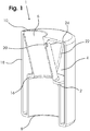
- Fig. 1 and Fig. 2 show an embodiment of the article 1 according to the invention, which is made by injection molding of plastic.
- the attachment is intended for attachment to a bottle (not shown) containing a first liquid.
- a bottle (not shown) containing a first liquid.
- it is a bottle that can be closed with a bottle cap.
- This first liquid is withdrawn through a bottle opening.
- the bottle opening is bounded by the bottle wall.
- the bottle opening is round and it is standardized for bottle caps.
- the bottle has a first portion, the bottle body, of the same diameter as the bottom of the bottle for opening the bottle extends.
- the bottle has a second portion, the bottleneck, extending from the bottle opening to the bottle body.
- the bottleneck has a diameter that widens from the bottle opening, which is significantly smaller in diameter than the bottom of the bottle, towards the bottle body so that the bottle neck makes the connection from the bottle mouth to the bottle body.
- the bottleneck has a bead in the region of the bottle opening, with which the bottle cap is engaged, which closes the bottle.
- the attachment has a contact surface 2, a reservoir 4 for a second fluid and a channel 6.
- the channel 6 establishes via an inlet opening 8 a connection between the bottle opening and an outlet 10 of the attachment after the attachment 1 has been placed on the bottle.
- the contact surface 2 is arranged in the channel 6. It is provided with a seal 12, which consists of elastic plastic and which was glued into the channel 6 after the preparation of the article by injection molding.
- the contact surface 2 can be formed in the channel 6 already in the manufacture of the essay, wherein for the preparation of the contact surface elastic material is to be used, which acts sealingly. But it is quite generally possible to manufacture the article of an elastic plastic material that acts sealing.
- the contact surface 2 is presently designed so that the arranged in the channel 6 seal 12 has a sealing profile 14 which rests positively after placement of the article on the bottle neck on the bead of the bottle neck or sealingly surrounds the bead of the bottle neck.
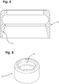
- Fig. 4, 5 show such a seal.
- the sealing profile 14 forms as negative the end of the bottle neck and the bottle opening, so that a bead on the neck of the bottle is gripped by the seal 12 in a form-fitting manner.
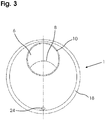
- the bottleneck is as shown in the Fig. 1 . 2 wider than the diameter of the bottle opening. Accordingly, the present embodiment of the article on a channel 6, which tapers on the contact surface 2. This taper is created by molding a shoulder 16 into the channel. The shoulder 16 can for particularly simple positioning of the seal 12 can be used. From the contact surface 2 or the shoulder 16 to the inlet opening, the diameter of the channel 6 is cylindrical and is dimensioned such that the bottleneck can be received in the channel 6. From the contact surface 2 to the outlet 10, the cross section of the channel tapers 6.
- the reservoir 4 is, as in Fig. 1 . 2 represented between the outer wall 18 of the article and the channel 6 is arranged. It is connected via a passage 20 to the channel 6.
- the second liquid contained in the reservoir 4 exits through the passage 20 into the channel 6 during emptying.
- the reservoir 4 can occupy the entire space between the outer wall 18 and channel 6 according to a simple embodiment. However, the reservoir 4 preferably occupies only a part of this space.
- the reservoir will after the in Fig. 1 . 2 shown, advantageous embodiment limited by a partition 22.
- the dividing wall 22 adjoins the outer wall 18 and / or the channel 6 and thereby defines the reservoir 4.
- the dividing wall 22 is preferably formed in such a way that the reservoir 4 in the attachment 1 is arranged such that when the bottle is emptied as far as possible or completely emptied.
- dead spaces should be avoided if possible, being regarded as dead spaces, the areas in the essay 1, which are below the passage 20 during the emptying of the essay.
- the passage 20 has a diameter which is determined in accordance with the channel 6 and the amount of liquid contained in the reservoir 4.
- the diameter is usually between 1 mm and 5 mm.
- the passage 20 is preferably arranged closer to the outlet 10 in the channel than to the inlet opening 8. In this way, a good mixture of first and second liquid is achieved during pouring.
- the reservoir 4 has a ventilation opening 24 on.
- the ventilation opening 24 is preferably formed in the outer wall 18 of the attachment 1 according to the invention. Via the ventilation opening 24, a pressure equalization during emptying of the reservoir 4 is ensured by the relatively small passage 20.
- a vent channel may be provided which extends with a first end at the vent opening in the outer wall of the cap to a second end, an opening in the reservoir.
- the opening in the reservoir is expedient at a location above the liquid level in the reservoir.
- the ventilation duct offers the advantage over a simple ventilation opening that the risk of leakage of liquid is minimized.
- the passage 20 and the vent opening 24 may be sealed together by a single closure, eg after filling the reservoir with the second liquid during transport. B. by a foil or a composite of plastic, metal or by a paper.
- the ventilation opening 24 has a diameter of preferably up to 2 mm.
- the closure for the passage 20 and the vent opening 24 is preferably glued and is withdrawn after placing the article 1 on the bottle. In this way, a reliable ventilation of the reservoir 4 is ensured, without which the desired removal of the second liquid from the reservoir 4 is not possible.
- the reservoir 4 can be filled through the passage 20 in a simple embodiment.
- the outer wall 18 of the cap 1 has a filling opening, which is closed by a corresponding cover.
- the cover can be made removable.
- the cover is inextricably connected to the attachment or to the outer wall, e.g. B. glued or welded.
- An approximately existing ventilation duct is preferably attached to the inside of the cover.
- the reservoir 4 can also be filled through the ventilation opening 24. A filling opening is then unnecessary.
- the article according to the invention can be produced in any desired manner, with plastic injection molding being particularly preferred.
- the attachment is made in one piece, apart from the possibly used cover, which is usually also produced by injection molding and usually placed only after filling of the reservoir.
- the cover may be made of the same material as the attachment or of another material, for. B. from another plastic, metal or composite material, eg. B. a fiber reinforced plastic.
- the reservoir 4 with the second liquid, for. As a juice or tea concentrate or an alcoholic liquid filled.
- the cover is applied to the filling opening.
- the passage 20 and the vent opening 24 by gluing a liquid-tight seal of z. B.
- the essay 1 is ready for transport and ready for use.
- the cap 1 is attached to the neck of the bottle by the bottle opening is inserted through the inlet opening 8 of the channel 6 in the channel 6 until the bottle opening or the bottle neck has come into engagement with the seal 12. This has created a liquid-tight connection.
- the bottle with the attachment 1 can now be drunk or poured.
- the bottle is tilted with the attachment 1 and the first liquid passes through the bottle opening in the channel 6, which opens into the outlet 10 from. While the first liquid in this way flows through the channel 6 lossless and exits from the outlet 10, the second liquid flows due to inclination of the attachment 1 through the passage 20 into the channel 6 and mixes with the first liquid.
- the above description uses a bottle cap as a representative embodiment. But it is applicable to all bottles, especially those in which the bottleneck has a bead. Various features of the essay can be freely combined.
Landscapes
- Engineering & Computer Science (AREA)
- Mechanical Engineering (AREA)
- Closures For Containers (AREA)
- Details Of Rigid Or Semi-Rigid Containers (AREA)
Description
- Die Erfindung betrifft einen Aufsatz für einen Flasche.
Zum Mischen von zwei Flüssigkeiten, beispielsweise für Mixgetränke, sind aus derWO 92/02434 A1 WO 2011/003048 A1 zeigt Aufsätze für Flaschen, die entweder auf die Flaschen aufgeschraubt werden, oder die mit einer außen liegenden Dichtung auf die Flaschen aufgesetzt sind. Eine Anordnung zum Mischen einer Flüssigkeit mit Feststoff-Aromen ist in derDE 20 2004 016 982 U1 offenbart. Ein Aufsatz wird auf die Flasche aufgesetzt. Ein Feststoff-Reservoir wird beim Aufsetzen des Aufsatzes im Flaschenhals angeordnet. Die aus der Flasche austretende Flüssigkeit durchströmt das zweite Reservoir, um die darin enthaltenen Aromen aufzunehmen. Eine technische Lösung, um eine Flüssigkeit, die in einer Flasche enthalten ist, mittels eines Aufsatzes mit einer zweiten Flüssigkeit zu mischen ist nicht bekannt. Da jedoch Mixgetränke aus zwei unterschiedlichen Flüssigkeiten sehr beliebt sind, besteht Bedarf an einer solchen Lösung.
DieDE 20 2008 008 018 U1 und dieDE 10 2012 110 833 zeigen Aufsätze für Dosen, bei denen separate Halteelemente den Aufsatz an der Dose fixieren und eine Dichtung mit dem Bördelrand bzw. Deckel der Dose in Eingriff bringen. Ein weiterer Aufsatz ist ausWO2011/003048 bekannt.
Es ist Aufgabe der Erfindung, einen Aufsatz für eine Flasche vorzuschlagen, der das Mischen der in der Flasche enthaltenen Flüssigkeit mit einer zweiten Flüssigkeit ermöglicht und die dabei möglichst einfach konstruiert ist.
Die Erfindung betrifft einen Aufsatz mit den Merkmalen des Anspruchs 1. - Der erfindungsgemäße Aufsatz ist für eine Flasche entwickelt, die eine erste Flüssigkeit aufnimmt, wobei die Flasche eine Flaschenöffnung aufweist und von einer Wand umgeben ist, und wobei der Aufsatz
- durch eine Außenwand von der Umgebung abgegrenzt ist und
- eine Anlagefläche zum abdichtenden Anliegen an die Flasche,
- ein Reservoir, das zum Aufnehmen einer zweiten Flüssigkeit ausgelegt ist,
- einen Kanal, der die Flaschenöffnung mit einem Auslass des Aufsatzes verbindet, sowie
- einen Durchlass aufweist, der das Reservoir mit dem Kanal verbindet. Erfindungsgemäß ist der Aufsatz zum Aufnehmen einer zweiten Flüssigkeit und zum konzentrischen Anbringen an der Flasche außerhalb der Flaschenöffnung ausgelegt und der Aufsatz ist mit einer Anlagefläche versehen, die eine Dichtung aufweist.
- Der erfindungsgemäße Aufsatz ist bevorzugt als Hohlkörper hergestellt, der von einem Kanal durchsetzt wird und der mit einer im oder am Kanal ausgebildeten Anlagefläche abdichtend auf die Flaschenöffnung oder den Flaschenhals aufgesteckt oder aufgesetzt werden kann. Dieser Aufsatz oder Hohlkörper ist bevorzugt zylindrisch oder eckig. Der Aufsatz kann aus sämtlichen Werkstoffen gefertigt werden, die sich für eine Lebensmittelverpackung eignen. Bevorzugt sind insbesondere Werkstoffe, die mit Spritzgussverfahren verarbeitet werden können, da der erfindungsgemäße Aufsatz bevorzugt als Spritzgussteil hergestellt wird. Der Aufsatz wird für den Gebrauch auf eine Flaschenöffnung einer geöffneten Flasche erfindungsgemäß aufgesetzt oder aufgesteckt und der Inhalt der Flasche wird durch die Flaschenöffnung und den daran anschließenden Kanal des Aufsatzes durch den Auslass des Aufsatzes entleert.
- Aus dem Vorstehenden ergibt sich, dass die Form des Aufsatzes weitgehend frei gewählt werden kann, vorausgesetzt, das Aufsetzen oder Aufstecken auf eine Flasche ist möglich. In einer einfachen Ausführung ist der Aufsatz zylindrisch mit parallel angeordneten Ober- und Unterseiten. Der Aufsatz kann aber auch eckig, insbesondere vieleckig, aber auch rund oder oval gestaltet sein.
Der besondere Vorteil des Aufsatzes ist, dass der Kunde frei entscheiden kann, welcher Flascheninhalt, also welche erste Flüssigkeit mit welcher zweiten Flüssigkeit kombiniert wird. Ob z. B. Mineralwasser mit Himbeersirup gemischt wird oder ob durch Aufsetzen auf eine Bierflasche eine Berliner Weiße erzeugt wird. Ob durch Kombinieren von Zitronenlimonade mit Pils ein Alsterwasser oder durch Mischen mit Weißbier ein alternatives Mischgetränk hergestellt wird.
Die Anlagefläche des erfindungsgemäßen Aufsatzes ist beliebig geformt. Sie ist bevorzugt als schmale, umlaufende Fläche ausgebildet. Die Anlagefläche ist erfindungsgemäß auch im Kanal des Aufsatzes angeordnet. Die Anlagefläche ist erfindungsgemäß aus einem Dichtungsmaterial hergestellt, das sich unter Verformung abdichtend an den Flaschenhals bzw. die Flaschenöffnung anschmiegt. Das Dichtungsmaterial ist bevorzugt elastisch und gleicht Unebenheiten an der Flaschenöffnung oder dem Flaschenhals aus, ohne dass die dichtende Wirkung der Anlagefläche verloren geht. Als Dichtungsmaterial werden bevorzugt elastische Werkstoffe eingesetzt. Dazu zählen insbesondere Gummi, Latex sowie elastische Kunststoffe. Das Dichtungsmaterial kann bei einem im Spritzgussverfahren hergestellten Aufsatz in einem Arbeitsgang mit dem Material des Aufsatzes verarbeitet werden oder das Dichtungsmaterial kann nachträglich am Aufsatz bzw. an oder in dessen Kanal angebracht werden. Es können auch vorgefertigte Dichtungen, z. B. aus elastischem Kunststoff an den oder in den Kanal geklebt werden, sofern der Klebstoff zur Verwendung in Lebensmittel-Verpackungen geeignet ist.
An sich genügt es, wenn die Anlagefläche als schmale Kante oder schmaler Streifen ausgebildet ist. Vorteilhaft ist die Anlagefläche jedoch als breiter Abschnitt am oder im Kanal ausgebildet, so dass eine sichere Abdichtung zwischen Aufsatz und Flasche gewährleistet wird und gleichzeitig auch die mechanische Stabilität des Aufsatzes auf der Flasche optimiert ist.
Nach einer erfindungsgemäßen Ausführung der Erfindung ist die Anlagefläche als Anlagewulst im Kanal ausgebildet. Dieser Anlagewulst kann den Wulst am Flaschenhals bzw. der Flaschenöffnung umgreifen oder hintergreifen, so dass die mechanische Stabilität der Verbindung und die Abdichtung weiter verbessert werden. Die Anlagefläche ist nach einer bevorzugten Ausführung dazu ausgelegt, mit der Behälterwand durch Klemmen oder Rasten verbunden zu werden, insbesondere, wenn die Anlagefläche als Anlagewulst ausgebildet ist. - Der besondere Vorteil dieser Ausführung des erfindungsgemäßen Aufsatzes ist es, dass kein Verschrauben oder andere Maßnahmen zum Fixieren des Aufsatzes an einer Flasche erforderlich sind. Das einfache Aufsetzen oder Aufstecken genügt.
Der Aufsatz weist ein Reservoir auf, das zur Aufnahme einer zweiten Flüssigkeit bestimmt ist. Das Reservoir wird von dem Material des Aufsatzes umschlossen und so gegenüber der Umgebung abgegrenzt. Das Reservoir kann beliebig geformt sein. Das Reservoir kann ein beliebiges Volumen aufweisen; bevorzugt ist das Volumen des Reservoirs jedoch geringer als das Volumen der Flasche, auf die der Aufsatz aufgesetzt wird. Das Verhältnis des Volumens vom Reservoir des Aufsatzes zum Volumen der Flasche beträgt bevorzugt 1 : 5 bis 1 : 100, vorteilhaft 1 : 10 bis 1 : 50. - Der Aufsatz weist einen Kanal auf, der eine Verbindung zwischen der Flaschenöffnung und einem Auslass des Aufsatzes herstellt. Der Kanal stellt damit eine Leitung bzw. eine Strömungsverbindung durch den Aufsatz hindurch her. Der Kanal nimmt in der Regel die Anlagefläche auf oder die Anlagefläche ist an einer Eingangsöffnung des Kanals angeordnet. In einer typischen Ausführung des Aufsatzes, der zur Verbindung mit einem runden Flaschenhals oder einer runden Flaschenöffnung bestimmt ist, ist der Aufsatz als zylindrischer Körper ausgebildet, der von einem Kanal durchsetzt ist. Im Kanal ist die Anlagefläche ausgebildet, so dass der Aufsatz auf die geöffnete Flasche aufgesteckt werden kann. Es entsteht ein etwa kreisringförmiger Körper, bei dem das Reservoir für eine zweite Flüssigkeit zwischen Kanal und einer Außenwand des Aufsatzes angeordnet ist.
- Der Kanal weist an dem der Eingangsöffnung gegenüberliegenden Ende einen Auslass auf. Bevorzugt ist der Auslass ergonomisch geformt, zum Beispiel als Ausguss oder als Trinköffnung. Der Kanal kann einen beliebigen Querschnitt aufweisen, z. B. um Anforderungen der Gestaltung des Aufsatzes besser nachzukommen. Eingangsöffnung und Auslass können unterschiedliche Querschnitte aufweisen, auch, um ein möglichst schnelles Entleeren der Flasche zu gewährleisten oder um eine möglichst kompakte Bauform des Aufsatzes zu gewährleisten. Der Kanal verbindet Eingangsöffnung und Auslass und kann zu diesem Zweck einen veränderlichen Querschnitt, sich verjüngenden oder sich erweiternden Querschnitt aufweisen, z. B. um die Strömungsverhältnisse beim Entnehmen der ersten Flüssigkeit oder der ersten und der zweien Flüssigkeit zu optimieren.
- Nach einer besonders vorteilhaften Ausführung des erfindungsgemäßen Aufsatzes ist die Eingangsöffnung des Aufsatzes konzentrisch angeordnet, während der Auslass erfindungsgemäß exzentrisch angeordnet ist und bevorzugt nahe an einer Kante des Aufsatzes mündet. Auf diese Weise ist das Trinken aus der Flasche bei aufgesetztem Aufsatz besonders einfach. Außerdem ist bei einem exzentrisch angeordneten Auslass die Lage der Flasche beim Entleeren definiert, denn der Auslass wird dann beim Entleeren der Flasche mit aufgesetztem Aufsatz zwingend am unteren Ende des Aufsatzes angeordnet sein. Durch diese definierte Anordnung des Auslasses kann vorteilhaft eine Entlüftungsöffnung für das
- Reservoir am während des Entleerens oberen Ende des Aufsatzes angeordnet sein.
Kanal und Reservoir des Aufsatzes sind weitgehend getrennt voneinander. Lediglich ein Durchlass ist zwischen Reservoir und Kanal vorgesehen, durch den die zweite Flüssigkeit bei auf die Flasche aufgesetztem Aufsatz während des Entleerens der Flasche aus dem Reservoir in den Kanal übergeht. Der Durchlass ist zwischen Eingangsöffnung und Auslass des Kanals, bevorzugt näher am Auslass, angeordnet. Er ist bei üblicher, senkrechter Ausrichtung des Aufsatzes, bei der der Auslass oberhalb der Eingangsöffnung des Kanals angeordnet ist, bevorzugt oberhalb des Pegels der zweiten Flüssigkeit im Reservoir angeordnet. Der Durchlass ist bevorzugt verschließbar, um ein unkontrolliertes Auslaufen der zweiten Flüssigkeit zu verhindern. Vorteilhaft ist der Verschluss des Durchlasses als Klebefolie aus Kunststoff, Metall, flüssigkeitsdichtem Papier oder einem Komposit-Werkstoff hergestellt. Ein Aufsatz mit derart verschlossenem bzw. versiegeltem Durchlass und ggf. versiegelter Entlüftungsöffnung wird bevorzugt in einer Umverpackung, z. B. einer Blisterverpackung oder einem Karton zum Verkauf angeboten.
Der Durchlass ist bevorzugt so bemessen, dass Flasche und Reservoir sich beim Entleeren gleichzeitig in gleichen Teilen entleeren, so dass ein konstantes Mischungsverhältnis von erster und zweiter Flüssigkeit erreicht wird. Der Durchlass des Aufsatzes steht vorteilhaft zur Flaschenöffnung in einem Größenverhältnis von 1 : 10 bis 1 : 200, besonders vorteilhaft von 1 : 20 bis 1 : 100.
Wie vorstehend beschrieben ist der Aufsatz durch seine Außenwand gegenüber der Umgebung abgegrenzt. Gleichzeitig ist der Aufsatz von dem Kanal durchsetzt. Zwischen Kanal und Außenwand ist das Reservoir aufgenommen. Dabei kann das Volumen des Aufsatzes größer sein als das zum Aufnehmen der zweiten Flüssigkeit erforderliche Reservoir, mindestens ist das Reservoir so groß bemessen, dass die vorgesehene Menge der zweiten Flüssigkeit aufgenommen werden kann. Das Reservoir ist häufig kreisringförmig um den Kanal herum angeordnet. Diese Anordnung ist Platz sparend, kann aber nachteilig sein, wenn Bereiche des Reservoirs beim Entleeren von Flasche und Aufsatz unterhalb des Kanals angeordnet sind. In diesen niedrig liegenden Bereichen des Reservoirs verbleiben Reste der zweiten Flüssigkeit, die beim Entleeren des Aufsatzes nicht durch den Durchlass in den Kanal gelangen, weil der Kanal oberhalb dieser niedrig liegenden Bereiche des Reservoirs angeordnet ist. Um ein vollständiges Entleeren des Reservoirs beim Leeren der Flasche zu gewährleisten, wird das Reservoir nach einer vorteilhaften Ausführung der Erfindung im Aufsatz durch eine Trennwand begrenzt. Die Trennwand ist so angeordnet, dass sie beim Entleeren des Behälters das Reservoir in der Weise begrenzt, dass die gesamte Menge der zweiten Flüssigkeit durch den Durchlass als tiefsten oder nahezu tiefsten Punkt des Reservoirs ausgegeben wird. Häufig ist die Trennwand während des Entleerens des Reservoirs etwa waagerecht angeordnet. Sie unterteilt den Innenraum des Aufsatzes in das Reservoir und einen leeren Totraum. - Der erfindungsgemäße Aufsatz kann nach einer vorteilhaften Ausführung auch so gestaltet sein, dass bei einer im Kanal angeordneten Anlagefläche bzw. einem Anlagewulst der Aufsatz in dem Bereich, der sich zwischen der Anlagefläche und der Eingangsöffnung des Kanals erstreckt, als einlagiger Wandabschnitt gestaltet ist, also als ein Abschnitt der Außenwand, der keinen Hohlraum einschließt.
Details der Erfindung werden nachfolgend an Hand von Figuren näher erläutert. Es zeigen: - Fig. 1
- einen Schnitt durch den erfindungsgemäßen Aufsatz (Sicht von der Seite)
- Fig. 2
- einen Längsschnitt durch den erfindungsgemäßen Aufsatz
- Fig. 3
- eine Ansicht des erfindungsgemäßen Aufsatzes von oben
- Fig. 4
- einen Schnitt durch eine Dichtung bzw. Anlagefläche
- Fig. 5
- eine Ansicht einer Dichtung
-
Fig. 1 undFig. 2 zeigen eine Ausführung des erfindungsgemäßen Aufsatzes 1, der im Spritzgussverfahren aus Kunststoff hergestellt ist. Der Aufsatz ist zum Anbringen an eine Flasche (hier nicht dargestellt) bestimmt, die eine erste Flüssigkeit enthält. Im vorliegenden Fall handelt es sich um eine mit einem Kronkorken verschließbare Flasche. Diese erste Flüssigkeit wird durch eine Flaschenöffnung entnommen. Die Flaschenöffnung wird durch die Flaschenwand umgrenzt. Die Flaschenöffnung ist rund und sie ist für Kronkorken-Flaschen genormt. Die Flasche weist einen ersten Abschnitt, den Flaschenkörper, auf, der sich mit demselben Durchmesser wie der Boden der Flasche, zur Flaschenöffnung hin erstreckt. Die Flasche weist einen zweiten Abschnitt, den Flaschenhals auf, der sich von der Flaschenöffnung zum Flaschenkörper erstreckt. Der Flaschenhals weist einen Durchmesser auf, der sich von der Flaschenöffnung, die einen deutlich geringeren Durchmesser aufweist als der Boden der Flasche, zum Flaschenkörper hin erweitert, so dass der Flaschenhals die Verbindung von der Flaschenöffnung zum Flaschenkörper herstellt. Der Flaschenhals weist im Bereich der Flaschenöffnung einen Wulst auf, mit dem der Kronkorken im Eingriff steht, der die Flasche verschließt.
Der Aufsatz weist eine Anlagefläche 2, ein Reservoir 4 für eine zweite Flüssigkeit und einen Kanal 6 auf. Der Kanal 6 stellt über eine Eingangsöffnung 8 eine Verbindung zwischen der Flaschenöffnung und einem Auslass 10 des Aufsatzes her, nachdem der Aufsatz 1 auf die Flasche gesteckt wurde. Die Anlagefläche 2 ist im Kanal 6 angeordnet. Sie ist mit einer Dichtung 12 versehen, die aus elastischem Kunststoff besteht und die nach der Herstellung des Aufsatzes im Spritzgussverfahren in den Kanal 6 eingeklebt wurde. Alternativ kann die Anlagefläche 2 im Kanal 6 bereits bei der Herstellung des Aufsatzes mit eingeformt werden, wobei zur Herstellung der Anlagefläche elastisches Material zu verwenden ist, das dichtend wirkt. Es ist aber ganz allgemein auch möglich, den Aufsatz aus einem elastischen Kunststoffmaterial zu fertigen, dass dichtend wirkt.
Die Anlagefläche 2 ist vorliegend so ausgelegt, dass die im Kanal 6 angeordnete Dichtung 12 ein Dichtungsprofil 14 aufweist, das nach dem Aufsetzen des Aufsatzes auf den Flaschenhals formschlüssig an dem Wulst des Flaschenhalses anliegt bzw. den Wulst des Flaschenhalses abdichtend umschließt.Fig. 4, 5 zeigen eine solche Dichtung. Vorteilhaft bildet das Dichtungsprofil 14 als Negativ das Ende des Flaschenhalses und die Flaschenöffnung ab, so dass ein Wulst am Flaschenhals von der Dichtung 12 formschlüssig umgriffen wird. Dadurch werden nicht nur Aufsatz und Flasche abdichtend verbunden. Zusätzlich wird auch die mechanische Stabilität der Verbindung verbessert.
Der Flaschenhals ist gemäß der Darstellung in denFig. 1 ,2 breiter als der Durchmesser der Flaschenöffnung. Entsprechend weist die vorliegende Ausführungsform des Aufsatzes einen Kanal 6 auf, der sich an der Anlagefläche 2 verjüngt. Diese Verjüngung wird durch das Einformen einer Schulter 16 in den Kanal erzeugt. Die Schulter 16 kann zum besonders einfachen Positionieren der Dichtung 12 genutzt werden. Von der Anlagefläche 2 bzw. der Schulter 16 bis zur Eingangsöffnung ist der Durchmesser des Kanals 6 zylindrisch und ist so bemessen, dass der Flaschenhals im Kanal 6 aufgenommen werden kann. Von der Anlagefläche 2 bis zum Auslass 10 verjüngt sich der Querschnitt des Kanals 6. Zudem verlagert sich der Verlauf des Kanals 6 im Aufsatz von einer zentrischen Position an der Anlagefläche 2 zu einer exzentrischen Position am Auslass 10. Diese Verlagerung des Verlaufs und die Verjüngung des Querschnitts, die ausFig. 3 ersichtlich sind, sind optional. Sie stellen aber eine bevorzugte Ausführung dar, weil dadurch eine zum Trinken oder Entleeren optimale Position des Auslasses 10 geschaffen wird. - Das Reservoir 4 ist, wie in
Fig. 1 ,2 dargestellt, zwischen der Außenwand 18 des Aufsatzes und dem Kanal 6 angeordnet. Es ist über einen Durchlass 20 mit dem Kanal 6 verbunden. Die im Reservoir 4 enthaltene zweite Flüssigkeit tritt beim Entleeren durch den Durchlass 20 in den Kanal 6 aus. Das Reservoir 4 kann nach einer einfachen Ausführungsform den gesamten Raum zwischen Außenwand 18 und Kanal 6 einnehmen. Bevorzugt nimmt das Reservoir 4 jedoch nur einen Teil dieses Raums ein. Das Reservoir wird nach der inFig. 1 ,2 gezeigten, vorteilhaften Ausführung durch eine Trennwand 22 begrenzt. Die Trennwand 22 grenzt an die Außenwand 18 und/oder den Kanal 6 an und definiert dadurch das Reservoir 4. Die Trennwand 22 ist bevorzugt in der Weise ausgebildet, dass das Reservoir 4 im Aufsatz 1 so angeordnet ist, dass es sich beim Entleeren der Flasche möglichst weitgehend oder vollständig entleert. Bei der Ausbildung und Anordnung des Reservoirs 4 sollen Toträume nach Möglichkeit vermieden werden, wobei als Toträume die Bereiche im Aufsatz 1 angesehen werden, die während des Ausleerens des Aufsatzes unterhalb des Durchlasses 20 liegen. - Der Durchlass 20 weist einen Durchmesser auf, der in Abstimmung auf den Kanal 6 und die Menge der im Reservoir 4 enthaltenen Flüssigkeit festgelegt wird. Der Durchmesser beträgt meist zwischen 1 mm und 5 mm. Der Durchlass 20 ist im Kanal bevorzugt näher zum Auslass 10 als zur Eingangsöffnung 8 angeordnet. Auf diese Weise wird beim Ausgießen eine gute Mischung von erster und zweiter Flüssigkeit erreicht.
Nach einer weiteren vorteilhaften Ausführung weist das Reservoir 4 eine Belüftungsöffnung 24 auf. Die Belüftungsöffnung 24 ist bevorzugt in der Außenwand 18 des erfindungsgemäßen Aufsatzes 1 ausgebildet. Über die Belüftungsöffnung 24 wird ein Druckausgleich beim Entleeren des Reservoirs 4 durch den verhältnismäßig kleinen Durchlass 20 gewährleistet. Alternativ kann ein Lüftungskanal vorgesehen sein, der sich mit einem ersten Ende an der Belüftungsöffnung in der Außenwand des Aufsatzes bis zu einem zweiten Ende, einer Öffnung in das Reservoir, erstreckt. Die Öffnung in das Reservoir ist zweckmäßig an einer Stelle oberhalb des Flüssigkeitspegels im Reservoir. Der Belüftungskanal bietet gegenüber einer einfachen Belüftungsöffnung den Vorteil, dass das Risiko des Auslaufens von Flüssigkeit minimiert wird. Zudem ist mittels des Lüftungskanals das Anordnen der Belüftungsöffnung nahe am Durchlass 20 möglich. Auf diese Weise können nach einer bevorzugten Ausführung der Erfindung der Durchlass 20 und die Belüftungsöffnung 24 nach dem Befüllen des Reservoirs mit der zweiten Flüssigkeit während des Transports gemeinsam durch einen einzigen Verschluss versiegelt werden, z. B. durch eine Folie oder ein Komposit aus Kunststoff, Metall oder durch ein Papier. Die Belüftungsöffnung 24 weist einen Durchmesser von bevorzugt bis zu 2 mm auf. Der Verschluss für den Durchlass 20 und die Belüftungsöffnung 24 ist vorzugsweise aufgeklebt und wird nach dem Aufsetzen des Aufsatzes 1 auf die Flasche abgezogen. Auf diese Weise ist eine zuverlässige Belüftung des Reservoirs 4 gewährleistet, ohne die die gewünschte Entnahme der zweiten Flüssigkeit aus dem Reservoir 4 nicht möglich ist. - Das Reservoir 4 kann in einer einfachen Ausführung durch den Durchlass 20 befüllt werden. Nach einer vorteilhaften Ausführung der Erfindung weist die Außenwand 18 des Aufsatzes 1 jedoch eine Befüllöffnung auf, die durch eine korrespondierende Abdeckung verschlossen wird. Die Abdeckung kann abnehmbar gestaltet sein. Bevorzugt wird die Abdeckung nach dem Befüllen des Reservoirs unlösbar mit dem Aufsatz bzw. mit der Außenwand verbunden, z. B. verklebt oder verschweißt. Ein etwa vorhandener Lüftungskanal ist bevorzugt an der Innenseite der Abdeckung angebracht. Alternativ kann das Reservoir 4 auch durch die Belüftungsöffnung 24 befüllt werden. Eine Befüllöffnung ist dann entbehrlich.
- Der erfindungsgemäße Aufsatz kann auf beliebige Weise hergestellt werden, besonders bevorzugt ist Spritzgießen mit Kunststoff. Bevorzugt wird der Aufsatz einteilig hergestellt, abgesehen von der ggf. verwendeten Abdeckung, die üblicherweise ebenfalls durch Spritzgießen hergestellt und meist erst nach dem Befüllen des Reservoirs aufgesetzt wird. Die Abdeckung kann aus demselben Werkstoff hergestellt sein wie der Aufsatz oder aus einem anderen Werkstoff, z. B. aus einem anderen Kunststoff, Metall oder Kompositwerkstoff, z. B. einem faserverstärkten Kunststoff.
Nach dem Herstellen des Aufsatzes 1, der eine Befüllöffnung aufweist, wird das Reservoir 4 mit der zweiten Flüssigkeit, z. B. ein Saft- oder Teekonzentrat oder einer alkoholischen Flüssigkeit befüllt. Dann wird die Abdeckung auf die Befüllöffnung aufgebracht. Vor dem Befüllen des Reservoirs 4 und dem Aufbringen der Abdeckung wurden der Durchlass 20 und die Belüftungsöffnung 24 durch Aufkleben eines flüssigkeitsdichten Siegels aus z. B. Aluminiumfolie verschlossen. Damit ist der Aufsatz 1 transportfertig und einsatzbereit.
Nach dem Öffnen einer Kronkorken-Flasche wird der Aufsatz 1 auf den Flaschenhals aufgesteckt, indem die Flaschenöffnung durch die Eingangsöffnung 8 des Kanals 6 in den Kanal 6 eingeführt wird, bis die Flaschenöffnung bzw. der Flaschenhals mit der Dichtung 12 in Eingriff gelangt ist. Dadurch ist eine flüssigkeitsdichte Verbindung entstanden. - Aus der Flasche mit dem Aufsatz 1 kann nun getrunken oder ausgegossen werden. Zu diesem Zweck wird die Flasche mit dem Aufsatz 1 geneigt und die erste Flüssigkeit tritt durch die Flaschenöffnung in den Kanal 6, der im Auslass 10 mündet, aus. Während die erste Flüssigkeit auf diese Weise verlustfrei durch den Kanal 6 strömt und aus dem Auslass 10 austritt, strömt die zweite Flüssigkeit infolge Neigung des Aufsatzes 1 durch den Durchlass 20 in den Kanal 6 und mischt sich mit der ersten Flüssigkeit.
Die vorstehende Beschreibung zieht als stellvertretendes Ausführungsbeispiel eine Kronkorken-Flasche heran. Sie ist aber auf alle Flaschen anwendbar, insbesondere solche, bei denen der Flaschenhals einen Wulst aufweist. Verschiedene Merkmale des Aufsatzes können frei kombiniert werden.
Die Flaschenöffnung wird nach dem Befüllen der Flasche bis zum Gebrauch verschlossen, z. B. mit einem Stopfen oder Kork, einem Drehverschluss oder mit einem Kronkorken. Die Flaschenöffnung oder der Flaschenhals weisen häufig einen Wulst auf, der zum einen Stabilität gegen Beschädigung verleiht und mit dem z. B. Kronkorken als Verschluss der Flaschenöffnung im Eingriff stehen. Aus der Flasche kann die darin enthaltene erste Flüssigkeit durch die Flaschenöffnung entnommen werden, beispielsweise durch Ausgießen oder durch Trinken direkt aus der Flasche.
Claims (5)
- Aufsatz (1) für eine Flasche, die eine erste Flüssigkeit aufnimmt, wobei die Flasche eine Flaschenöffnung aufweist und von einer Wand umgeben ist, und wobei der Aufsatz (1)- durch eine Außenwand von der Umgebung abgegrenzt ist und- eine Anlagefläche (2) zum abdichtenden Anliegen an die Flasche,- ein Reservoir (4), das zum Aufnehmen einer zweiten Flüssigkeit ausgelegt ist,- einen Kanal (6), der die Flaschenöffnung mit einem Auslass (10) des Aufsatzes (1) verbindet, sowie- einen Durchlass (20) aufweist, der das Reservoir (4) mit dem Kanal (6) verbindet, wobei- der Aufsatz (1) zum konzentrischen Anbringen an der Flasche außerhalb der Flaschenöffnung, nämlich zum Aufstecken auf die Flasche ausgelegt ist und der Aufsatz eine Anlagefläche (2) aufweist, die mit einer Dichtung (12) versehen ist, dadurch gekennzeichnet, dass der Kanal (6) einen Auslass (10) aufweist, der, bezogen auf den Umfang des Aufsatzes (1), exzentrisch angeordnet ist, und dass der Kanal (6) auf einer Eingangsseite des Aufsatzes (1) eine bezogen auf den Umfang des Aufsatzes (1) konzentrisch angeordnete Eingangsöffnung aufweist.
- Aufsatz nach Anspruch 1, dadurch gekennzeichnet, dass das Reservoir (4) außerhalb des Umfangs der Flaschenöffnung angebracht ist.
- Aufsatz nach einem der Ansprüche 1 oder 2, dadurch gekennzeichnet, dass das Reservoir (4) überwiegend oberhalb der Flaschenöffnung angeordnet ist.
- Aufsatz nach mindestens einem der vorangehenden Ansprüche, dadurch gekennzeichnet, dass eine Trennwand zum Begrenzen des Reservoirs vorgesehen ist.
- Aufsatz nach mindestens einem der vorangehenden Ansprüche, dadurch gekennzeichnet, dass das Reservoir (4) mit einer Belüftungsöffnung (24) versehen ist.
Applications Claiming Priority (2)
| Application Number | Priority Date | Filing Date | Title |
|---|---|---|---|
| DE102014101073.6A DE102014101073B4 (de) | 2014-01-29 | 2014-01-29 | Aufsatz für eine Flasche |
| PCT/EP2015/051585 WO2015113963A1 (de) | 2014-01-29 | 2015-01-27 | Aufsatz für eine flasche |
Publications (2)
| Publication Number | Publication Date |
|---|---|
| EP3099599A1 EP3099599A1 (de) | 2016-12-07 |
| EP3099599B1 true EP3099599B1 (de) | 2018-11-28 |
Family
ID=52484437
Family Applications (1)
| Application Number | Title | Priority Date | Filing Date |
|---|---|---|---|
| EP15705213.5A Not-in-force EP3099599B1 (de) | 2014-01-29 | 2015-01-27 | Aufsatz für eine flasche |
Country Status (5)
| Country | Link |
|---|---|
| US (1) | US9944451B2 (de) |
| EP (1) | EP3099599B1 (de) |
| DE (1) | DE102014101073B4 (de) |
| ES (1) | ES2712400T3 (de) |
| WO (1) | WO2015113963A1 (de) |
Families Citing this family (2)
| Publication number | Priority date | Publication date | Assignee | Title |
|---|---|---|---|---|
| DE102017005112A1 (de) * | 2017-03-23 | 2018-09-27 | Christian Kehlenbeck | Behälter zur Aufnahme eines Getränkes und Umhüllung |
| USD892615S1 (en) * | 2017-08-11 | 2020-08-11 | Harald Ruhnau | Dosing closure |
Citations (1)
| Publication number | Priority date | Publication date | Assignee | Title |
|---|---|---|---|---|
| US20100001018A1 (en) * | 2008-07-04 | 2010-01-07 | Puma Samuel C | Dispenser for pressurized beverage bottle |
Family Cites Families (17)
| Publication number | Priority date | Publication date | Assignee | Title |
|---|---|---|---|---|
| US2171302A (en) * | 1938-10-08 | 1939-08-29 | Wheeling Steel Corp | Gasketed fitting |
| US2372281A (en) * | 1942-01-29 | 1945-03-27 | Herman J Jordan | Dispenser and control for the same |
| US2661870A (en) | 1948-09-28 | 1953-12-08 | Alfred G Huenergardt | Multiple liquid dispensing container |
| US2947453A (en) * | 1956-04-19 | 1960-08-02 | American Flange & Mfg | Closure and reversible spout assemblies for containers |
| US3059816A (en) * | 1957-02-19 | 1962-10-23 | Schenley Ind Inc | Combination container closure and pouring device |
| US3206074A (en) | 1962-09-18 | 1965-09-14 | Colgate Palmolive Co | Multiple compartmented dispensing package |
| DE3220693A1 (de) | 1982-06-02 | 1983-12-08 | Gerd Henrich Hans 8951 Stötten Borges | Flasche fuer getraenke |
| US4730381A (en) | 1986-03-27 | 1988-03-15 | The Procter & Gamble Company | Method of making plural-chambered dispensing device exhibiting constant proportional co-dispensing |
| GB9017132D0 (en) | 1990-08-04 | 1990-09-19 | Cameron Price Ernest J | Beverage packages |
| GB9118792D0 (en) | 1991-09-03 | 1991-10-16 | Tarwinski Edmund C | Beverage mixing device |
| DE202004016982U1 (de) | 2004-05-27 | 2005-10-06 | Grothklags, Jan | Wiederverschließbarer Trinkaufsatz für Getränkeflaschen mit integriertem Container für einen Geschmacksstoff |
| WO2006047795A1 (en) * | 2004-10-27 | 2006-05-04 | Geoffrey Charles Wolf | Sealable container for drinking and temporarily sealing bottles |
| KR20090010005A (ko) * | 2007-07-21 | 2009-01-28 | 조영국 | 소리가 발생하는 캐릭터 및 빨대고정 캡 |
| DE202008008018U1 (de) * | 2008-06-14 | 2008-09-25 | Harlander, Michael | Aufsatzbehälter für einen Getränkebehälter |
| US8365960B1 (en) * | 2009-03-26 | 2013-02-05 | Fadi Kalaouze | Multi-compartment beverage container |
| JP5499011B2 (ja) | 2011-11-17 | 2014-05-21 | 富士重工業株式会社 | 車外環境認識装置および車外環境認識方法 |
| DE102012110833B3 (de) * | 2012-11-12 | 2013-12-24 | Harald Ruhnau | Aufsatz für einen Flüssigkeitsbehälter |
-
2014
- 2014-01-29 DE DE102014101073.6A patent/DE102014101073B4/de not_active Expired - Fee Related
-
2015
- 2015-01-27 WO PCT/EP2015/051585 patent/WO2015113963A1/de not_active Ceased
- 2015-01-27 ES ES15705213T patent/ES2712400T3/es active Active
- 2015-01-27 US US15/111,547 patent/US9944451B2/en not_active Expired - Fee Related
- 2015-01-27 EP EP15705213.5A patent/EP3099599B1/de not_active Not-in-force
Patent Citations (1)
| Publication number | Priority date | Publication date | Assignee | Title |
|---|---|---|---|---|
| US20100001018A1 (en) * | 2008-07-04 | 2010-01-07 | Puma Samuel C | Dispenser for pressurized beverage bottle |
Also Published As
| Publication number | Publication date |
|---|---|
| US20160325912A1 (en) | 2016-11-10 |
| US9944451B2 (en) | 2018-04-17 |
| ES2712400T3 (es) | 2019-05-13 |
| DE102014101073B4 (de) | 2016-06-16 |
| WO2015113963A1 (de) | 2015-08-06 |
| EP3099599A1 (de) | 2016-12-07 |
| DE102014101073A1 (de) | 2015-07-30 |
Similar Documents
| Publication | Publication Date | Title |
|---|---|---|
| EP2178765B1 (de) | Selbstöffner-verschluss mit lufteinlasskanal für verbundpackungen oder für mit folienmaterial zu verschliessende behälterstutzen | |
| EP2238043B1 (de) | Verschluss zum zudosieren einer separaten flüssigsubstanz | |
| EP1465575A1 (de) | Einschwei -schiffchen für einen beutel | |
| EP2917132B1 (de) | Aufsatz für einen flüssigkeitsbehälter | |
| EP0358083B1 (de) | Verpackung für Nahrungsmittel | |
| DE202008008018U1 (de) | Aufsatzbehälter für einen Getränkebehälter | |
| DE102014101073B4 (de) | Aufsatz für eine Flasche | |
| DE102010049727B4 (de) | Einstellbarer Trinkflaschenverschluß mit Trinkhalmfunktion | |
| DE102006032509A1 (de) | Verschlussvorrichtung für einen Trinkbehälter | |
| AT509898B1 (de) | Mehrkammerbehälter mit mindestens zwei mit ausgiessbarem inhalt befüllten behältern | |
| EP2559633A1 (de) | Eimerdeckel mit integrierter Kammer | |
| WO2022248483A1 (de) | Behälterverschluss | |
| WO2006122612A1 (de) | Aufsatz für flaschen zur herstellung von mischgetränken | |
| DE102014101361B4 (de) | Verschlusselement für einen Getränkebehälter | |
| CH716958A1 (de) | Adapter zum Verbinden eines Nachfüllbehälters mit einem Behälter während eines Nachfüllvorgangs. | |
| WO2019210893A1 (de) | Container mit einer ersten zu mischenden flüssigkeit | |
| DE2233565C3 (de) | Hermetisches Verschlußsystem für Thermosflaschen und ähnliche Behälter | |
| DE102006028912B4 (de) | Verschlussvorrichtung für einen Trinkbehälter | |
| DE3843861A1 (de) | Aus einer kunststoff-folie tiefgezogener behaelter | |
| DE102011004669A1 (de) | Kunststoffverschluss mit Dosierbecher | |
| DE202014102598U1 (de) | Verzehreinheit mit Getränk und Verpackung | |
| DE7914131U1 (de) | In der Ausgabeoeffnung vob giess- oder fliessfaehige Stoffe aufnehmenden Behaeltern dichtend anbringbares Aufsatzteil | |
| DE2235279A1 (de) | Wiederverschliessbarer, tiefgezogener kunststoffbehaelter | |
| DE29512241U1 (de) | Schraubverschluß für Weithals-Flaschen u.dgl. Behälter | |
| DE2233565B2 (de) | Hermetisches verschlussystem fuer thermosflaschen und aehnliche behaelter |
Legal Events
| Date | Code | Title | Description |
|---|---|---|---|
| PUAI | Public reference made under article 153(3) epc to a published international application that has entered the european phase |
Free format text: ORIGINAL CODE: 0009012 |
|
| STAA | Information on the status of an ep patent application or granted ep patent |
Free format text: STATUS: REQUEST FOR EXAMINATION WAS MADE |
|
| 17P | Request for examination filed |
Effective date: 20160804 |
|
| AK | Designated contracting states |
Kind code of ref document: A1 Designated state(s): AL AT BE BG CH CY CZ DE DK EE ES FI FR GB GR HR HU IE IS IT LI LT LU LV MC MK MT NL NO PL PT RO RS SE SI SK SM TR |
|
| AX | Request for extension of the european patent |
Extension state: BA ME |
|
| DAX | Request for extension of the european patent (deleted) | ||
| STAA | Information on the status of an ep patent application or granted ep patent |
Free format text: STATUS: EXAMINATION IS IN PROGRESS |
|
| 17Q | First examination report despatched |
Effective date: 20170714 |
|
| GRAP | Despatch of communication of intention to grant a patent |
Free format text: ORIGINAL CODE: EPIDOSNIGR1 |
|
| STAA | Information on the status of an ep patent application or granted ep patent |
Free format text: STATUS: GRANT OF PATENT IS INTENDED |
|
| INTG | Intention to grant announced |
Effective date: 20180703 |
|
| GRAS | Grant fee paid |
Free format text: ORIGINAL CODE: EPIDOSNIGR3 |
|
| GRAA | (expected) grant |
Free format text: ORIGINAL CODE: 0009210 |
|
| STAA | Information on the status of an ep patent application or granted ep patent |
Free format text: STATUS: THE PATENT HAS BEEN GRANTED |
|
| AK | Designated contracting states |
Kind code of ref document: B1 Designated state(s): AL AT BE BG CH CY CZ DE DK EE ES FI FR GB GR HR HU IE IS IT LI LT LU LV MC MK MT NL NO PL PT RO RS SE SI SK SM TR |
|
| REG | Reference to a national code |
Ref country code: CH Ref legal event code: EP |
|
| REG | Reference to a national code |
Ref country code: AT Ref legal event code: REF Ref document number: 1069969 Country of ref document: AT Kind code of ref document: T Effective date: 20181215 |
|
| REG | Reference to a national code |
Ref country code: DE Ref legal event code: R096 Ref document number: 502015006990 Country of ref document: DE |
|
| REG | Reference to a national code |
Ref country code: IE Ref legal event code: FG4D Free format text: LANGUAGE OF EP DOCUMENT: GERMAN |
|
| REG | Reference to a national code |
Ref country code: NL Ref legal event code: MP Effective date: 20181128 |
|
| REG | Reference to a national code |
Ref country code: LT Ref legal event code: MG4D |
|
| PG25 | Lapsed in a contracting state [announced via postgrant information from national office to epo] |
Ref country code: NO Free format text: LAPSE BECAUSE OF FAILURE TO SUBMIT A TRANSLATION OF THE DESCRIPTION OR TO PAY THE FEE WITHIN THE PRESCRIBED TIME-LIMIT Effective date: 20190228 Ref country code: BG Free format text: LAPSE BECAUSE OF FAILURE TO SUBMIT A TRANSLATION OF THE DESCRIPTION OR TO PAY THE FEE WITHIN THE PRESCRIBED TIME-LIMIT Effective date: 20190228 Ref country code: LT Free format text: LAPSE BECAUSE OF FAILURE TO SUBMIT A TRANSLATION OF THE DESCRIPTION OR TO PAY THE FEE WITHIN THE PRESCRIBED TIME-LIMIT Effective date: 20181128 Ref country code: FI Free format text: LAPSE BECAUSE OF FAILURE TO SUBMIT A TRANSLATION OF THE DESCRIPTION OR TO PAY THE FEE WITHIN THE PRESCRIBED TIME-LIMIT Effective date: 20181128 Ref country code: IS Free format text: LAPSE BECAUSE OF FAILURE TO SUBMIT A TRANSLATION OF THE DESCRIPTION OR TO PAY THE FEE WITHIN THE PRESCRIBED TIME-LIMIT Effective date: 20190328 Ref country code: LV Free format text: LAPSE BECAUSE OF FAILURE TO SUBMIT A TRANSLATION OF THE DESCRIPTION OR TO PAY THE FEE WITHIN THE PRESCRIBED TIME-LIMIT Effective date: 20181128 Ref country code: HR Free format text: LAPSE BECAUSE OF FAILURE TO SUBMIT A TRANSLATION OF THE DESCRIPTION OR TO PAY THE FEE WITHIN THE PRESCRIBED TIME-LIMIT Effective date: 20181128 |
|
| REG | Reference to a national code |
Ref country code: ES Ref legal event code: FG2A Ref document number: 2712400 Country of ref document: ES Kind code of ref document: T3 Effective date: 20190513 |
|
| PG25 | Lapsed in a contracting state [announced via postgrant information from national office to epo] |
Ref country code: GR Free format text: LAPSE BECAUSE OF FAILURE TO SUBMIT A TRANSLATION OF THE DESCRIPTION OR TO PAY THE FEE WITHIN THE PRESCRIBED TIME-LIMIT Effective date: 20190301 Ref country code: SE Free format text: LAPSE BECAUSE OF FAILURE TO SUBMIT A TRANSLATION OF THE DESCRIPTION OR TO PAY THE FEE WITHIN THE PRESCRIBED TIME-LIMIT Effective date: 20181128 Ref country code: AL Free format text: LAPSE BECAUSE OF FAILURE TO SUBMIT A TRANSLATION OF THE DESCRIPTION OR TO PAY THE FEE WITHIN THE PRESCRIBED TIME-LIMIT Effective date: 20181128 Ref country code: RS Free format text: LAPSE BECAUSE OF FAILURE TO SUBMIT A TRANSLATION OF THE DESCRIPTION OR TO PAY THE FEE WITHIN THE PRESCRIBED TIME-LIMIT Effective date: 20181128 Ref country code: PT Free format text: LAPSE BECAUSE OF FAILURE TO SUBMIT A TRANSLATION OF THE DESCRIPTION OR TO PAY THE FEE WITHIN THE PRESCRIBED TIME-LIMIT Effective date: 20190328 |
|
| PG25 | Lapsed in a contracting state [announced via postgrant information from national office to epo] |
Ref country code: NL Free format text: LAPSE BECAUSE OF FAILURE TO SUBMIT A TRANSLATION OF THE DESCRIPTION OR TO PAY THE FEE WITHIN THE PRESCRIBED TIME-LIMIT Effective date: 20181128 |
|
| PG25 | Lapsed in a contracting state [announced via postgrant information from national office to epo] |
Ref country code: PL Free format text: LAPSE BECAUSE OF FAILURE TO SUBMIT A TRANSLATION OF THE DESCRIPTION OR TO PAY THE FEE WITHIN THE PRESCRIBED TIME-LIMIT Effective date: 20181128 Ref country code: CZ Free format text: LAPSE BECAUSE OF FAILURE TO SUBMIT A TRANSLATION OF THE DESCRIPTION OR TO PAY THE FEE WITHIN THE PRESCRIBED TIME-LIMIT Effective date: 20181128 Ref country code: IT Free format text: LAPSE BECAUSE OF FAILURE TO SUBMIT A TRANSLATION OF THE DESCRIPTION OR TO PAY THE FEE WITHIN THE PRESCRIBED TIME-LIMIT Effective date: 20181128 Ref country code: DK Free format text: LAPSE BECAUSE OF FAILURE TO SUBMIT A TRANSLATION OF THE DESCRIPTION OR TO PAY THE FEE WITHIN THE PRESCRIBED TIME-LIMIT Effective date: 20181128 |
|
| REG | Reference to a national code |
Ref country code: DE Ref legal event code: R097 Ref document number: 502015006990 Country of ref document: DE |
|
| PG25 | Lapsed in a contracting state [announced via postgrant information from national office to epo] |
Ref country code: RO Free format text: LAPSE BECAUSE OF FAILURE TO SUBMIT A TRANSLATION OF THE DESCRIPTION OR TO PAY THE FEE WITHIN THE PRESCRIBED TIME-LIMIT Effective date: 20181128 Ref country code: EE Free format text: LAPSE BECAUSE OF FAILURE TO SUBMIT A TRANSLATION OF THE DESCRIPTION OR TO PAY THE FEE WITHIN THE PRESCRIBED TIME-LIMIT Effective date: 20181128 Ref country code: SM Free format text: LAPSE BECAUSE OF FAILURE TO SUBMIT A TRANSLATION OF THE DESCRIPTION OR TO PAY THE FEE WITHIN THE PRESCRIBED TIME-LIMIT Effective date: 20181128 Ref country code: SK Free format text: LAPSE BECAUSE OF FAILURE TO SUBMIT A TRANSLATION OF THE DESCRIPTION OR TO PAY THE FEE WITHIN THE PRESCRIBED TIME-LIMIT Effective date: 20181128 Ref country code: MC Free format text: LAPSE BECAUSE OF FAILURE TO SUBMIT A TRANSLATION OF THE DESCRIPTION OR TO PAY THE FEE WITHIN THE PRESCRIBED TIME-LIMIT Effective date: 20181128 |
|
| REG | Reference to a national code |
Ref country code: CH Ref legal event code: PL |
|
| PG25 | Lapsed in a contracting state [announced via postgrant information from national office to epo] |
Ref country code: LU Free format text: LAPSE BECAUSE OF NON-PAYMENT OF DUE FEES Effective date: 20190127 |
|
| PLBE | No opposition filed within time limit |
Free format text: ORIGINAL CODE: 0009261 |
|
| STAA | Information on the status of an ep patent application or granted ep patent |
Free format text: STATUS: NO OPPOSITION FILED WITHIN TIME LIMIT |
|
| REG | Reference to a national code |
Ref country code: BE Ref legal event code: MM Effective date: 20190131 |
|
| REG | Reference to a national code |
Ref country code: IE Ref legal event code: MM4A |
|
| PG25 | Lapsed in a contracting state [announced via postgrant information from national office to epo] |
Ref country code: SI Free format text: LAPSE BECAUSE OF FAILURE TO SUBMIT A TRANSLATION OF THE DESCRIPTION OR TO PAY THE FEE WITHIN THE PRESCRIBED TIME-LIMIT Effective date: 20181128 |
|
| 26N | No opposition filed |
Effective date: 20190829 |
|
| PG25 | Lapsed in a contracting state [announced via postgrant information from national office to epo] |
Ref country code: BE Free format text: LAPSE BECAUSE OF NON-PAYMENT OF DUE FEES Effective date: 20190131 |
|
| PG25 | Lapsed in a contracting state [announced via postgrant information from national office to epo] |
Ref country code: LI Free format text: LAPSE BECAUSE OF NON-PAYMENT OF DUE FEES Effective date: 20190131 Ref country code: CH Free format text: LAPSE BECAUSE OF NON-PAYMENT OF DUE FEES Effective date: 20190131 |
|
| PG25 | Lapsed in a contracting state [announced via postgrant information from national office to epo] |
Ref country code: IE Free format text: LAPSE BECAUSE OF NON-PAYMENT OF DUE FEES Effective date: 20190127 |
|
| PG25 | Lapsed in a contracting state [announced via postgrant information from national office to epo] |
Ref country code: TR Free format text: LAPSE BECAUSE OF FAILURE TO SUBMIT A TRANSLATION OF THE DESCRIPTION OR TO PAY THE FEE WITHIN THE PRESCRIBED TIME-LIMIT Effective date: 20181128 |
|
| PG25 | Lapsed in a contracting state [announced via postgrant information from national office to epo] |
Ref country code: MT Free format text: LAPSE BECAUSE OF FAILURE TO SUBMIT A TRANSLATION OF THE DESCRIPTION OR TO PAY THE FEE WITHIN THE PRESCRIBED TIME-LIMIT Effective date: 20181128 |
|
| REG | Reference to a national code |
Ref country code: AT Ref legal event code: MM01 Ref document number: 1069969 Country of ref document: AT Kind code of ref document: T Effective date: 20200127 |
|
| PG25 | Lapsed in a contracting state [announced via postgrant information from national office to epo] |
Ref country code: CY Free format text: LAPSE BECAUSE OF FAILURE TO SUBMIT A TRANSLATION OF THE DESCRIPTION OR TO PAY THE FEE WITHIN THE PRESCRIBED TIME-LIMIT Effective date: 20181128 Ref country code: AT Free format text: LAPSE BECAUSE OF NON-PAYMENT OF DUE FEES Effective date: 20200127 |
|
| PG25 | Lapsed in a contracting state [announced via postgrant information from national office to epo] |
Ref country code: HU Free format text: LAPSE BECAUSE OF FAILURE TO SUBMIT A TRANSLATION OF THE DESCRIPTION OR TO PAY THE FEE WITHIN THE PRESCRIBED TIME-LIMIT; INVALID AB INITIO Effective date: 20150127 |
|
| PGFP | Annual fee paid to national office [announced via postgrant information from national office to epo] |
Ref country code: GB Payment date: 20220125 Year of fee payment: 8 Ref country code: DE Payment date: 20220126 Year of fee payment: 8 |
|
| PGFP | Annual fee paid to national office [announced via postgrant information from national office to epo] |
Ref country code: FR Payment date: 20220120 Year of fee payment: 8 Ref country code: ES Payment date: 20220216 Year of fee payment: 8 |
|
| PG25 | Lapsed in a contracting state [announced via postgrant information from national office to epo] |
Ref country code: MK Free format text: LAPSE BECAUSE OF FAILURE TO SUBMIT A TRANSLATION OF THE DESCRIPTION OR TO PAY THE FEE WITHIN THE PRESCRIBED TIME-LIMIT Effective date: 20181128 |
|
| REG | Reference to a national code |
Ref country code: DE Ref legal event code: R119 Ref document number: 502015006990 Country of ref document: DE |
|
| GBPC | Gb: european patent ceased through non-payment of renewal fee |
Effective date: 20230127 |
|
| PG25 | Lapsed in a contracting state [announced via postgrant information from national office to epo] |
Ref country code: GB Free format text: LAPSE BECAUSE OF NON-PAYMENT OF DUE FEES Effective date: 20230127 Ref country code: DE Free format text: LAPSE BECAUSE OF NON-PAYMENT OF DUE FEES Effective date: 20230801 |
|
| PG25 | Lapsed in a contracting state [announced via postgrant information from national office to epo] |
Ref country code: FR Free format text: LAPSE BECAUSE OF NON-PAYMENT OF DUE FEES Effective date: 20230131 |
|
| REG | Reference to a national code |
Ref country code: ES Ref legal event code: FD2A Effective date: 20240403 |
|
| PG25 | Lapsed in a contracting state [announced via postgrant information from national office to epo] |
Ref country code: ES Free format text: LAPSE BECAUSE OF NON-PAYMENT OF DUE FEES Effective date: 20230128 |
|
| PG25 | Lapsed in a contracting state [announced via postgrant information from national office to epo] |
Ref country code: ES Free format text: LAPSE BECAUSE OF NON-PAYMENT OF DUE FEES Effective date: 20230128 |