EP3100017B1 - Elektromechanisches miniaturisiertes gerät zur druckmessung - Google Patents
Elektromechanisches miniaturisiertes gerät zur druckmessung Download PDFInfo
- Publication number
- EP3100017B1 EP3100017B1 EP15708306.4A EP15708306A EP3100017B1 EP 3100017 B1 EP3100017 B1 EP 3100017B1 EP 15708306 A EP15708306 A EP 15708306A EP 3100017 B1 EP3100017 B1 EP 3100017B1
- Authority
- EP
- European Patent Office
- Prior art keywords
- pressure
- sensor member
- processing means
- electro
- mechanical
- Prior art date
- Legal status (The legal status is an assumption and is not a legal conclusion. Google has not performed a legal analysis and makes no representation as to the accuracy of the status listed.)
- Active
Links
Images



Classifications
-
- G—PHYSICS
- G01—MEASURING; TESTING
- G01L—MEASURING FORCE, STRESS, TORQUE, WORK, MECHANICAL POWER, MECHANICAL EFFICIENCY, OR FLUID PRESSURE
- G01L27/00—Testing or calibrating of apparatus for measuring fluid pressure
- G01L27/002—Calibrating, i.e. establishing true relation between transducer output value and value to be measured, zeroing, linearising or span error determination
-
- B—PERFORMING OPERATIONS; TRANSPORTING
- B81—MICROSTRUCTURAL TECHNOLOGY
- B81B—MICROSTRUCTURAL DEVICES OR SYSTEMS, e.g. MICROMECHANICAL DEVICES
- B81B3/00—Devices comprising flexible or deformable elements, e.g. comprising elastic tongues or membranes
- B81B3/0018—Structures acting upon the moving or flexible element for transforming energy into mechanical movement or vice versa, i.e. actuators, sensors, generators
- B81B3/0021—Transducers for transforming electrical into mechanical energy or vice versa
-
- C—CHEMISTRY; METALLURGY
- C07—ORGANIC CHEMISTRY
- C07F—ACYCLIC, CARBOCYCLIC OR HETEROCYCLIC COMPOUNDS CONTAINING ELEMENTS OTHER THAN CARBON, HYDROGEN, HALOGEN, OXYGEN, NITROGEN, SULFUR, SELENIUM OR TELLURIUM
- C07F9/00—Compounds containing elements of Groups 5 or 15 of the Periodic Table
- C07F9/02—Phosphorus compounds
- C07F9/547—Heterocyclic compounds, e.g. containing phosphorus as a ring hetero atom
- C07F9/6558—Heterocyclic compounds, e.g. containing phosphorus as a ring hetero atom containing at least two different or differently substituted hetero rings neither condensed among themselves nor condensed with a common carbocyclic ring or ring system
- C07F9/65586—Heterocyclic compounds, e.g. containing phosphorus as a ring hetero atom containing at least two different or differently substituted hetero rings neither condensed among themselves nor condensed with a common carbocyclic ring or ring system at least one of the hetero rings does not contain nitrogen as ring hetero atom
-
- G—PHYSICS
- G01—MEASURING; TESTING
- G01L—MEASURING FORCE, STRESS, TORQUE, WORK, MECHANICAL POWER, MECHANICAL EFFICIENCY, OR FLUID PRESSURE
- G01L15/00—Devices or apparatus for measuring two or more fluid pressure values simultaneously
-
- G—PHYSICS
- G01—MEASURING; TESTING
- G01L—MEASURING FORCE, STRESS, TORQUE, WORK, MECHANICAL POWER, MECHANICAL EFFICIENCY, OR FLUID PRESSURE
- G01L27/00—Testing or calibrating of apparatus for measuring fluid pressure
- G01L27/007—Malfunction diagnosis, i.e. diagnosing a sensor defect
-
- G—PHYSICS
- G01—MEASURING; TESTING
- G01L—MEASURING FORCE, STRESS, TORQUE, WORK, MECHANICAL POWER, MECHANICAL EFFICIENCY, OR FLUID PRESSURE
- G01L9/00—Measuring steady of quasi-steady pressure of fluid or fluent solid material by electric or magnetic pressure-sensitive elements; Transmitting or indicating the displacement of mechanical pressure-sensitive elements, used to measure the steady or quasi-steady pressure of a fluid or fluent solid material, by electric or magnetic means
- G01L9/0001—Transmitting or indicating the displacement of elastically deformable gauges by electric, electro-mechanical, magnetic or electro-magnetic means
- G01L9/0008—Transmitting or indicating the displacement of elastically deformable gauges by electric, electro-mechanical, magnetic or electro-magnetic means using vibrations
-
- B—PERFORMING OPERATIONS; TRANSPORTING
- B81—MICROSTRUCTURAL TECHNOLOGY
- B81B—MICROSTRUCTURAL DEVICES OR SYSTEMS, e.g. MICROMECHANICAL DEVICES
- B81B2201/00—Specific applications of microelectromechanical systems
- B81B2201/02—Sensors
- B81B2201/0264—Pressure sensors
Definitions
- the present invention relates to the field of pressure sensor devices, particularly miniaturized electro-mechanical sensor devices, for use to measure pressures over a wide range (from overpressures but with the exception of high vacuum conditions), for example in machines, plants or instruments for measurements and analyses.
- a first category of devices comprises devices of the Pirani or thermo-cross type or devices of the MacLeod type, which are however considered as "low-end” devices, in terms of performance and measurement precision. Therefore, these devices cannot be used for many applications that require high precision and wider measurement ranges.
- a second category of devices comprises diaphragm capacitive pressure sensors, which are considered "high-end” devices, in terms of performance and measurement precision.
- a first drawback of these capacitive pressure sensors is the range of measurable pressures, that is rather narrow for a given device. Therefore, in order to measure a pressure over a wide range of pressures, multiple pressure sensors have to be used in parallel: for example at least three capacitive pressure sensors in parallel are typically required for measurements over a pressures range between 10 -4 mbar and 10 3 mbar, and no commercial instruments capable to measure pressures ranging from 10 -4 mbar to 10 4 mbar are known
- the individual pressure measurement devices must include not only the pressure sensor itself, but also further components (for example, processing modules, interface modules, either wired or wireless, towards higher-level controllers, etc.).
- each of these devices becomes a "system", even though of small dimensions. Disadvantageously, this reduces the reliability and increases the complexity of the devices, also increasing design and maintenance costs.
- a field of application having a great and growing importance, is related to the use of pressure measurement systems/devices inside production machines or plants or manufacturing environments or analysis and measurement instruments, where it may be necessary to measure the pressure with a high precision, in many different points, over wide ranges, in often unfavorable environmental conditions, resulting in critical, or even extreme, operating conditions for the devices.
- the existing solutions do not offer a solution, or, at the most, they allow performing remote control procedures, by means of high level system controllers, which manage, for example, a plurality of devices in a plant. These control procedures may be complex and costly, in terms of time and resources needed.
- the known sensor devices may have several drawbacks, among which: the non-perfect repeatability of pressure measurements, for example during pressure cycles of an industrial process; the existence of severe limitations of use in applications providing the exposure to corrosive gases environments; the difficulty of use in environments having abundant soot and particulate; the need to extract the device, from the system where it works, for calibration or re-calibration or cleaning, every time a new process cycle starts; finally, the need for a complex and cumbersome management and measurement system to obtain a microscopic measurement signal using macroscopic measurement and management instruments of the device.
- the object of the present invention is to devise and provide a miniaturized electro-mechanical device for pressure measurements over a wide range (and a related measurement method), which results to be improved such as to fulfill the above-mentioned needs, and to be able to at least partially overcome the drawbacks described above with reference to the prior art.
- the United States Patent Application US 2011/0239772 A1 relates to the technical field of pressure transducers, and, in particular, describes a pressure transducer with compensation for non-pressure effects (temperature and acceleration).
- a method for measuring pressure, carried out by the device of the invention, is defined in claim 9.
- a further embodiment of the method is defined in claim 10.
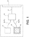
- This device 1 comprises at least one first electro-mechanical miniaturized pressure sensor member 11, configured to detect a first pressure value P 1 and to generate a first electrical signal S 1 representative of the above-mentioned first pressure value P 1 .
- the device 1 also comprises at least one second electro-mechanical miniaturized pressure sensor member 12, configured to detect a respective second pressure value P 2 and to generate a second electrical signal S 2 representative of the above-mentioned second pressure value P 2 .
- the second electro-mechanical miniaturized pressure sensor member 12 is arranged within a respective casing 13 suitable to seal the second sensor member.
- the device 1 then comprises electronic processing means 10, which are operatively connected to the first and second sensor members (11 and 12, respectively) and are configured to determine a measured pressure value P based on the first and second electrical signals (respectively, S 1 and S 2 ), generated by the sensor members 11, 12, and received by the electronic processing means 10.
- the device 1 also comprises interface means 15, operatively connected to the electronic processing means 10, and configured to provide in output the above-mentioned measured pressure value P.
- the at least one first sensor member 11, the at least one second sensor member 12, the electronic processing means 10 and the interface means 15 are all included in a single integrated device.
- integrated device is meant herein a device that is manufactured by means of integrated micro/nano-electronic techniques and that is contained, or containable in a single, individual package.
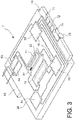
- the device 1 is an integrated device made by means of a single chip 20 (shown for example in Fig. 3 ), typically made of silicon.
- the first and second sensor members, the electronic processing means and the interface means are all included, i.e., integrated, in the chip 20 of the integrated device 1.
- the device 1 comprises two half-chips, which are connected to each other also at a microscopic level.
- the device 1 may comprise multiple chips connected to each other at a microscopic scale, or an individual multi-layer chip, such as to obtain anyway an integrated device.
- miniaturized device can be also understood, i.e., a device which, being integrated, has a size in the micrometric scale, for example of an overall order of magnitude of hundreds of ⁇ m 2 or of mm 2 , which size is still lower than the minimum size that can be handled and operated, wherein such minimum size is obtained by providing the device with a suitable packaging.
- first and second sensor members can be implemented, in principle, by means of any electro-mechanical transducer able to provide an electrical variable representing the detected pressure.
- first 11 and second 12 sensor members are configured to have a mechanical or electro-mechanical behaviour, respectively correlated to a first and to a second mechanical or electro-mechanical variable (for example, position, or movement, or oscillation) depending on the pressure (P 1 , P 2 , respectively) or on the fluid-dynamics to which the sensor members are respectively subjected.
- a mechanical or electro-mechanical behaviour respectively correlated to a first and to a second mechanical or electro-mechanical variable (for example, position, or movement, or oscillation) depending on the pressure (P 1 , P 2 , respectively) or on the fluid-dynamics to which the sensor members are respectively subjected.
- first 11 and second 12 sensor members are further configured to either generate or transform the above-mentioned first S 1 and second electrical signal S 2 (representative of the first and second pressure values P 1 and P 2 , respectively) based on the respective first and second mechanical or electro-mechanical variables that are sensible to pressure or to fluid-dynamics.
- the amplitude or resonance frequency or width of the spectrum peak or other electrical variables of the electrical signals S 1 and S 2 can be correlated and can represent (according to per-se known theoretical perspectives) a pressure value detected by the respective sensor member.
- the two sensor members in a preferred exemplary embodiment, are identical, and are designed to behave in the same way, based on the same principles and on the same variables.
- the two sensor members can even differ from each other, as long as the correlation of their behaviours is precisely known, such as to allow to define a "nominal behaviour” and, as it will be better explained herein below, to identify possible deviations of the first sensor member 11 from such "nominal behaviour".
- first 11 and second 12 sensor members are similar to each other, and each of them comprises a respective oscillating member of the MEMS/NEMS (Micro/Nano -Electro-Mechanical System) type.
- MEMS/NEMS Micro/Nano -Electro-Mechanical System
- such MEMS/NEMS-type oscillating member comprises a micro-cantilever configured to oscillate with a dynamic response depending on the pressure to which it is subjected.
- a first micro-cantilever that is the first sensor member
- a second micro-cantilever that is the second sensor member
- the second micro-cantilever is represented in a dashed line, because it is actually covered by the casing 13, in the illustrated views.
- the micro-cantilever operating principle provides that the characterizing electro-mechanical variable is related to the oscillation: the micro-cantilever oscillates with a frequency damping with a damping factor ⁇ depending on the pressure to which it is subjected. Therefore, it is able to generate an electrical signal (i.e. S 1 or S 2 ) whose dynamic response is representative of the pressure to which the micro-cantilever is subjected.
- the damping factor ⁇ is inversely proportional to the thickness d of the micro-cantilever. Therefore, the miniaturization of the micro-cantilever (and, generally speaking, of the sensor member) is an important aspect in order to allow the device of the invention to perform measures over a whole pressure value range that is especially wide.
- each of the two micro-cantilever 11, 12 is excited by applying a forcing waveform having a known frequency.
- the device may further comprise a function generator circuit or frequency generator 51, configured to cause an input oscillation at each of the first and second micro-cantilevers, by means of an excitation signal.
- the electronic processing means 10 comprise a processing unit 52 and a demodulating circuit 53, configured to estimate first and second output oscillation frequencies of the first and second micro-cantilevers, respectively, based on the frequency of the first electrical signal S 1 or of the reference electrical signal S 2 , respectively, and of the excitation signal; the demodulating circuit 53 then communicates to the processing unit 52 an information related to these first and second oscillation frequencies and excitation signal frequency.
- this demodulating circuit 53 is a signal lock-in circuit.
- the embodiment illustrated above is actually based on a double MEMS/NEMS oscillator, integrated in the device, where the two MEMS/NEMS oscillators share the frequency generation and demodulation lock-in circuit, and are instead characterized by the first and second micro-cantilevers, as the respective active member.
- the frequency generation circuit 51 "excites" both micro-cantilevers, and the lock-in circuit 53 detects the output oscillation frequencies of both micro-cantilevers 11, 12, thereby providing a signal depending on the comparison of these two output frequencies with the reference excitation signal(s).
- the device can be configured to detect the pressure based on one or more characteristics of the electrical signals S 1 and S 2 : for example, based on a variation of the oscillation frequency relative to a nominal (or forcing) frequency; or based on a broadening of the oscillation peak, as visible in the spectrum of each electrical signal; or by measuring its Q factor.
- micro-cantilever oscillators among which those reported in Hosaka et al., "Damping characteristics of beam-shaped micro-oscillators", Sensors and Actuators A 49 (1995), 87-95 , may be cited for example.
- the micro-cantilevers of the first and second sensor members are configured to oscillate in a parallel direction relative to the surface of the chip 20 forming the device.
- the micro-cantilevers of the first and second sensor members are configured to oscillate in a perpendicular direction relative to the surface of the chip 20 forming the device.
- the sealing and protective casing 13 is configured to adopt a closed state and an open state: in the closed state, it protects the at least one second sensor member 12 from being directly exposed to the surrounding environment; in the open state, it allows the at least one second sensor member to be directly exposed to the surrounding environment.
- the casing 13 thereby encloses the reference sensor member 12, thus protecting it from degradation phenomena possibly resulting from environmental conditions, while keeping the pressure conditions fixed and stabilized on a known value (that will be herein called “reference pressure” since it is a certain and absolute reference point), which is defined a priori.
- reference pressure a known value
- the second sensor member 12 keeps the "nominal behaviour", for which it has been carefully characterized a priori, with a good or excellent accuracy.
- the second sensor member takes the important function of a "reference sensor”, having a stable and anyway predictable behaviour, even during operation.
- the electro-mechanical or mechatronic properties of the second reference sensor member 12 are known, since they have been characterized a priori with respect to the reference pressure, for example, as a function of operating temperature, oscillation frequency, oscillation amplitude, and so on; and they have been further stored in a memory included in the electronic processing means 10.
- the characterization data of the second sensor member actually define a "reference hypersurface" allowing to know exactly the mechatronic properties of the reference sensor member and the operating conditions (for example, operating temperature), based on the second electrical signal S 2 generated by the second sensor member 12, and being known the reference pressure to which the second sensor member 12 is subjected inside the sealed casing.
- the processing means 10 when the processing means 10 receive an electrical signal S 2 from the second sensor member 12, they refer it to the known reference pressure value P 2 , as maintained inside the sealed casing 13, and thus, based on the stored characterization data, the processing means 10 can know both the mechatronic properties and the operating conditions of the reference sensor member 12. Consequently, the processing means 10 are also able to calculate the exact conversion factor existing between S 2 and P 2 (which will be herein designated as "second conversion factor").
- the operating conditions of the two sensor members 11 and 12, which are very close to each other, are the same, except for the pressure.
- the mechatronic properties of the two sensor members are nominally the same (if the two sensor members are exactly identical) or at least they are correlated to each other in a known and deterministic way (if the two sensor members are not identical) depending on preset design criteria.
- the processing means 10 are able to calculate a suitable conversion factor (which will be designated herein as "first conversion factor” or “calibration factor”) to be applied to the signal S 1 generated by the first sensor member 11, to calculate exactly the pressure value P to which the first sensor member 11, thus the device 1, is subjected, i.e., the value to be measured.
- first conversion factor or “calibration factor”
- the first and second conversion factors can be exactly the same or they can be correlated to each other in a known and deterministic manner, based on the initial characterization, and varying, e.g., as a function of the pressure range over which the device is working.
- the processing means 10 are capable to estimate more accurately the actual pressure present at the device, i.e., the measured pressure P, by taking into account both the first and the second electrical signals.
- the methodologies of estimate of the pressure P, based on the electrical signals S 1 and S 2 representative of the pressures P 1 e P 2 detected by the first 11 and by the second sensor member 12, can be various, also different from what described above by way of example.
- the device comprises a plurality of second sensor members 12, in order to detect a respective plurality of second pressure values P 2 , and generate a respective plurality of second electrical signals S 2 representative of such second pressure values P 2 ; the electronic processing means 10 are further configured to generate the measured pressure value P based on a processing of said second electrical signals S 2 .
- the plurality of "reference sensors" can be exploited both to improve the estimate precision, along the whole measurement range of the device, and for the sake of redundancy and reliability.
- the electronic processing means 10 are configured to process data received from the first 11 and second 12 sensor members and, based on such received data, to carry out a diagnostic procedure on the first sensor member 11, such as to identify potential hysteresis phenomena and/or imperfections and/or potential thermal and/or mechanical drifts which the first sensor member is subject to.
- the signals S 1 and S 2 are compared.
- This condition happens for example when both the environment pressure (e.g., at the end of an operating cycle) and the reference pressure are a vacuum pressure (for example UHV), maintained in the casing by means of a pressure control member ("getter"); or when the environment pressure is different from vacuum but is known, and a similar pressure is created by the "getter” in the casing 13.
- UHV vacuum pressure
- the device 1 is capable to carry out a diagnostic procedure even if the pressure of the external environment is not known, or if it does not coincide with the reference pressure.
- the casing 13 is temporarily opened, such as to temporarily expose the second sensor member 12 to the same environment to which the first sensor member 11 is exposed. Then, the diagnostic procedure is performed, and finally the casing 13 is closed and sealed again and the reference pressure conditions are restored, for example by means of an embedded "getter”.
- the electronic processing means 10 are also configured to carry out an adjusting and/or compensation and/or optimization procedure of the first sensor member, to correct and/or compensate hysteresis and/or imperfections and/or identified drifts, based on the results of the diagnostic procedure.
- the electronic processing means 10 are configured to store desired operating conditions of the first sensor member 11, to compare the desired operating conditions to operating conditions detected by a diagnostic procedure, and to intervene, based on such a comparison, by means of an adjustment procedure, to recover the desired operating conditions and guarantee the repeatability of the performed measurements.
- the device 1 further comprises controlled heating means, comprising one or more temperature sensors 61, e.g., miniaturized thermometer(s), and at least one heating member 62 (for example, one or more micro-resistors), placed near or over the first sensor member 11, and a heat supply (or “heater”) 63, typically associated to a supply and management circuit 64 of the heating means, which is connected to an external supply interface 65.
- controlled heating means comprising one or more temperature sensors 61, e.g., miniaturized thermometer(s), and at least one heating member 62 (for example, one or more micro-resistors), placed near or over the first sensor member 11, and a heat supply (or “heater”) 63, typically associated to a supply and management circuit 64 of the heating means, which is connected to an external supply interface 65.
- the above-mentioned controlled heating means are configured to carry out a degassing and/or a removal of gases adsorbed on the surface of the micro-cantilever 11 of the first sensor member 11, under the control of the electronic processing means 10, which in turn operate based on the temperature detected by the thermometer 61 and on the results of the diagnostic procedure.
- the above-mentioned adjusting procedure of the first sensor member 11 comprises the degassing and/or removal of gases adsorbed on the surface of the micro-cantilever 11, by means of the controlled heating means.
- the above-mentioned heater 63 can be used to vary the operating thermal conditions of the device, in a controlled manner, also in further operating steps other than self-adjusting.
- the device further comprises protection thin films, for example technical and specific films, configured to reduce the adsorption of process gases (for example hydrophobic films to prevent the adsorption of moisture present in the process environment) and to prevent corrosion phenomena.
- protection thin films are arranged such as to cover at least the first sensor member 11.
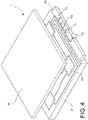
- the device further comprises a package 80 comprising micrometric frame filters, and/or anti-particulate filters, arranged such as to cover at least the sensor members 11, 12, comprised in the device 1, and configured to protect them from particulate or soot.
- a package 80 comprising micrometric frame filters, and/or anti-particulate filters, arranged such as to cover at least the sensor members 11, 12, comprised in the device 1, and configured to protect them from particulate or soot.
- the electronic processing means 10 comprise at least one electronic processor (CPU) 52 integrated in the device 1. This CPU can then operate as an embedded on-chip programmable microprocessor.
- CPU electronic processor
- the interface means 15 comprise input and output means, either wireless or wired and/or with pins.
- this interface can interact with the external world (for example with an external plant control system) in a versatile and adaptable manner, both to transmit and to receive information and/or signals and/or commands.
- the interface means 15 comprise both wired input means 71 and a wireless transmitter 70 (for example a WiFi transmitter), to remotely transmit signals from closed operation areas (such as tyres, pump internal zones and vacuum chambers), and output pins 72 able to provide for example a direct analog output signal and/or a digital TTL output signal and/or an interface for a serial communication protocol.
- a wireless transmitter 70 for example a WiFi transmitter
- closed operation areas such as tyres, pump internal zones and vacuum chambers
- output pins 72 able to provide for example a direct analog output signal and/or a digital TTL output signal and/or an interface for a serial communication protocol.
- the presence of a CPU 52 and of an interface 15, integrated in the device, allows the device 1 to receive and send information (for example, control signals) from and to a higher-level control system, for example the operative control system of the plant/environment where the device operates. Thereby, the device 1 is completely integrated in the operative plant/environment.
- information for example, control signals
- the device 1 comprises further integrated electronic circuitry, comprising one or more of the following electronics circuits: dedicated I/O management circuits, a supply and management circuit 64 of the heating member.
- auxiliary electronic circuits optionally present in the device 1 (frequency generator 51, lock-in circuit 52, heater 53, dedicated I/O management circuits, etc.) have been illustrated above. These auxiliary electronic circuits are integrated in the device 1. Optionally, they can be made in the same chip 20 containing the sensor members 11, 12, the processing means 10 and interface means 15, or in further chips, also micro-connected to the above-mentioned main chip, such as to constitute the integrated device.
- Figs. 3 , 5A-5B and 6 With reference to the structural aspects of the device, particularly to the case where it comprises only one chip 20, three different embodiments are illustrated in Figs. 3 , 5A-5B and 6 by way of example. These different embodiments share all the components and the structural aspects previously described, which are therefore illustrated using the same numerical references.
- the embodiments differ in the way the components are arranged in the device, particularly in the single chip 20 comprised in the device.
- the first 11 and second 12 sensor members and the electronic processing means 10 are arranged on the same side of the chip 20 forming the device 1.
- the first 11 sensor member is arranged on one side of the chip 20, while the second sensor member 12 and the electronic processing means 10 are arranged on the other side of the chip 20 forming the device.
- Fig. 5A shows one side of the chip
- 5B shows the other side of the chip
- This second embodiment offers the advantage of segregating the heating member 62 (micro-resistor) with respect to the other components of the device, reducing the heat dissipation issues. Moreover, the other components are placed on the side of chip faced towards higher pressure or atmospheric pressure areas, such as they can be more easily cooled.
- the first 11 and second 12 sensor members and the electronic processing means 10 are arranged such as to project as a relief, on different planes, with respect to the surface of the chip 20 composing the device.
- the device 1 in all the embodiments and related variations illustrated above, is configured to detect pressures ranging over a wide interval.
- This wide range is the range permitted by the above-mentioned physical phenomena, on which the device is based, and enabled by the miniaturized dimensions of the sensor members.
- This range can be, according to a non-limiting example, from 10 -5 mbar to 10 5 mbar (thus, only excluding extremely low pressure or high vacuum values)
- the device 1 is configured to detect pressure values between 10 -4 mbar and 10 4 mbar.
- the method comprises the steps of detecting a first pressure value P 1 and generating a first electrical signal S 1 representative of the first pressure value P 1 , by at least one first electro-mechanical miniaturized pressure sensor member 11 of the device 1; similarly, detecting a second pressure value P 2 and generating a second electrical signal S 2 representative of the second pressure value P 2 , by at least one second miniaturized electro-mechanical sensor member 12 of the device 1, arranged within a respective casing 13 that is suitable to seal it.
- the method then comprises the step of determining, by the electronic processing means 10, a measured pressure value P based on the above-mentioned first and second electrical signals, S 1 and S 2 ; and finally providing in output the measured pressure value P, by interface means 15 of the device 1.
- the first 11 and second 12 sensor members, the electronic processing means 10 and the interface means 15 are all comprised in a single integrated device.
- the method further comprises the steps of storing, in the electronic processing means 10, characterization data of the second sensor member 12, at a reference pressure P 2 ; keeping the second sensor member 12 at the reference pressure P 2 , inside the casing 13; calibrating the first sensor member 11 and the second sensor member 12, by the electronic processing means 10, based on the second electrical signal S 2 and on the above-mentioned characterization data.
- the method further comprises the steps of arranging the same pressure in the first 11 and second 12 sensor members; comparing the first S 1 and second electrical signal S 2 generated thereby; operating a diagnostic procedure of the operation of the first sensor member 11.
- the method comprises the further step of heating in a controlled way the first sensor member 11, to carry out a degassing and/or a removal of gases adsorbed therein.
- the object of the present invention is achieved by the system described above, by virtue of the illustrated characteristics.
- the device of the present invention is a miniaturized device capable of providing high precision and reliability performance.
- the device due to the structural and functional characteristics described above, results to be self-contained (capable of self-calibration and self-diagnostic). It is also able to deal with, and to correct to a certain extent, the several degradation causes which may actually happen and which would worsen the device performance, by affecting the first sensor member.
- the device allows, as illustrated above, to manage microscopic signals at microscopic level, with the consequent further advantage to enhance the achievable signal-to-noise ratios.
Landscapes
- Chemical & Material Sciences (AREA)
- General Physics & Mathematics (AREA)
- Physics & Mathematics (AREA)
- Organic Chemistry (AREA)
- Health & Medical Sciences (AREA)
- Engineering & Computer Science (AREA)
- Analytical Chemistry (AREA)
- Biomedical Technology (AREA)
- Biochemistry (AREA)
- General Health & Medical Sciences (AREA)
- Molecular Biology (AREA)
- Life Sciences & Earth Sciences (AREA)
- Computer Hardware Design (AREA)
- Microelectronics & Electronic Packaging (AREA)
- Measuring Fluid Pressure (AREA)
Claims (10)
- Elektromechanische miniaturisierte Vorrichtung (1) für Druckmessungen, umfassend:- wenigstens ein erstes elektromechanisches miniaturisiertes Drucksensorelement (11), welches dazu eingerichtet ist, einen jeweiligen ersten Druckwert (P1) zu erfassen und ein erstes elektrisches Signal (S1) zu erzeugen, welches für den ersten Druckwert (P1) repräsentativ ist;- wenigstens ein zweites elektromechanisches miniaturisiertes Drucksensorelement (12), welches innerhalb eines jeweiligen Gehäuses (13) angeordnet ist, welches dazu geeignet ist, das zweite elektromechanische miniaturisierte Drucksensorelement (12) abzudichten und zu bewirken, dass das zweite elektromechanische miniaturisierte Drucksensorelement (12) in einer abgedichteten Umgebung arbeitet;- elektronische Verarbeitungsmittel (10), welche betriebsmäßig mit dem ersten (11) und dem zweiten (12) Sensorelement verbunden sind, welche dazu eingerichtet sind, einen gemessenen Druckwert (P) zu bestimmen;- Schnittstellenmittel (15), welche betriebsmäßig mit den elektronischen Verarbeitungsmitteln (10) verbunden sind und dazu eingerichtet sind, in einer Ausgabe den gemessenen Druckwert (P) bereitzustellen,wobei:- das zweite elektromechanische miniaturisierte Drucksensorelement (12) dazu eingerichtet ist, einen jeweiligen zweiten Druckwert (P2) zu erfassen und ein zweites elektrisches Signal (S2) zu erzeugen, welches für den zweiten Druckwert (P2) repräsentativ ist;- die elektronischen Verarbeitungsmittel (10) dazu eingerichtet sind, den gemessenen Druckwert (P) auf Grundlage des ersten (S1) und des zweiten (S2) elektrischen Signals zu bestimmen;- das erste (11) und das zweite (12) Sensorelement, die elektronischen Verarbeitungsmittel (10) und die Schnittstellenmittel (15) in einer einzelnen integrierten Vorrichtung umfasst sind;- die elektronischen Verarbeitungsmittel (10) dazu eingerichtet sind, von dem ersten (11) und dem zweiten (12) Sensorelement empfangene Daten zu verarbeiten und auf Grundlage der empfangenen Daten ein Diagnoseverfahren des ersten Sensorelements (11) auszuführen, um mögliche Hysterese-Phänomene und/oder Fehler und/oder mögliche thermische und/oder mechanische Abweichungen zu identifizieren, welchen das erste Sensorelement (11) ausgesetzt sein kann; wobei die elektronischen Verarbeitungsmittel (10) dazu eingerichtet sind, in dem Fall, dass das Diagnoseverfahren ein negatives Ergebnis ergibt, ein Anpassungs- und/oder ein Kompensierungs- und/oder ein Optimierungsverfahren des ersten Sensorelements (11) auszuführen, um Hysterese-Phänomene und/oder Fehler und/oder Abweichungen zu korrigieren und/oder zu kompensieren, welche auf Grundlage der Resultate des Diagnoseverfahrens identifiziert sind;wobei die elektromechanische miniaturisierte Vorrichtung (1) dadurch gekennzeichnet ist, dass
jedes des ersten (11) und des zweiten (12) elektromechanischen miniaturisierten Drucksensorelements ein jeweiliges Schwingelement des MEMS-/NEMS-Typs umfasst,
wobei jedes der Schwingelemente des MEMS-/NEMS-Typs einen Mikroausleger (11, 12) umfasst, welcher dazu eingerichtet ist, mit einer dynamischen Reaktion zu schwingen, welche von dem Druck abhängig ist, welchem er ausgesetzt ist,
und dass
die elektromechanische miniaturisierte Vorrichtung (1) ferner gesteuerte/geregelte Heizmittel (61, 62, 63, 64) umfasst, welche dazu eingerichtet sind, unter der Steuerung/Regelung der elektronischen Verarbeitungsmittel (10) ein Entgasen und/oder ein Entfernen von Gasen auszuführen, welche auf Oberflächen des Mikroauslegers des ersten Sensorelements (11) adsorbiert sind, und wobei das Anpassungsverfahren des ersten Sensorelements (11) das Entgasen und/oder das Entfernen von Gasen umfasst, welche auf den Oberflächen des Mikroauslegerelements (11) adsorbiert sind. - Vorrichtung (1) nach Anspruch 1, wobei das erste (11) und das zweite (12) Sensorelement, die elektronischen Verarbeitungsmittel (10) und die Schnittstellenmittel (15) in einem einzelnen Chip (20) der integrierten Vorrichtung umfasst sind.
- Vorrichtung (1) nach einem der Ansprüche 1 oder 2, wobei jedes des ersten (11) und des zweiten (12) Sensorelements dazu eingerichtet ist, ein mechanisches oder elektromechanisches Verhalten aufzuweisen, welches sich auf wenigstens eine jeweilige erste oder zweite mechanische oder elektromechanische Variable bezieht, welche von dem Druck oder von der Fluiddynamik abhängig ist, welchen es ausgesetzt ist,
und wobei jedes des ersten (S1) oder des zweiten (S2) elektrischen Signals jeweils auf Grundlage wenigstens einer jeweiligen ersten oder zweiten mechanischen oder elektromechanischen Variable erzeugt wird. - Vorrichtung (1) nach einem der vorhergehenden Ansprüche, umfassend eine Mehrzahl zweiter Drucksensorelemente (12), um eine jeweilige Mehrzahl zweiter Druckwerte (P2) zu erfassen und um eine jeweilige Mehrzahl zweiter elektrischer Signale (S2) zu erzeugen, welche für die zweiten Druckwerte (P2) repräsentativ sind;
und wobei die elektronischen Verarbeitungsmittel (10) ferner dazu eingerichtet sind, den gemessenen Druckwert (P) auf Grundlage einer Verarbeitung der zweiten elektrischen Signale (S2) zu erzeugen. - Vorrichtung (1) nach einem der vorhergehenden Ansprüche, wobei das Gehäuse (13) dazu eingerichtet ist, einen geschlossenen Zustand einzunehmen, in welchem es das wenigstens eine zweite Sensorelement (12), es bei einem Referenzdruck haltend, welcher mit dem zweiten Druckwert (P2) übereinstimmt, gegen eine direkte Exposition gegenüber der umgebenden Umgebung schützt,wobei die elektronischen Verarbeitungsmittel (10) einen Speicher umfassen, welcher dazu eingerichtet ist, Charakterisierungsdaten zu speichern, welche das zweite Sensorelement (12) bei dem Referenzdruck (P2) charakterisieren,und wobei die elektronischen Verarbeitungsmittel (10) dazu eingerichtet sind, das erste (11) und das zweite (12) Sensorelement auf Grundlage des zweiten elektrischen Signals (S2) und der gespeicherten Charakterisierungsdaten zu kalibrieren.
- Vorrichtung (1) nach einem der vorhergehenden Ansprüche, ferner umfassend dünne Schutzfilme, welche dazu eingerichtet sind, die Adsorption von Verarbeitungsgasen zu verringern und Korrosionsphänomene zu verhindern, und derart angeordnet sind, dass sie wenigstens das erste Sensorelement (11) abdecken,
oder ferner umfassend eine Einheit (80), welche Mikrorahmenfilter umfasst, welche derart angeordnet sind, dass sie wenigstens die in der Vorrichtung (1) umfassten Sensorelemente (11, 12) abdecken. - Vorrichtung (1) nach Anspruch 2, wobei das erste (11) und das zweite (12) Sensorelement und die elektronischen Verarbeitungsmittel (10) an der gleichen Seite des Chips (20) angeordnet sind, welcher die Vorrichtung (1) bildet,oder wobei das erste Sensorelement (11) in Bezug auf das zweite Sensorelement (12) und die elektronischen Verarbeitungsmittel (10) an einer entgegengesetzten Seite des Chips (20) angeordnet ist,oder wobei das erste (11) und das zweite (12) Sensorelement und die elektronischen Verarbeitungsmittel (10) derart angeordnet sind, dass sie in Bezug auf die Oberfläche des Chips (20), welcher die Vorrichtung (1) bildet, in verschiedenen Ebenen als ein Relief vorstehen.
- Vorrichtung (1) nach einem der vorhergehenden Ansprüche, welche dazu eingerichtet ist, Druckwerte im Bereich zwischen 10-4 mbar und 104 mbar zu erfassen.
- Verfahren zur Druckmessung, welches durch eine elektromechanische miniaturisierte Vorrichtung (1) ausgeführt wird, wobei das Verfahren umfasst:- Erfassen eines ersten Druckwerts (P1) und Erzeugen eines ersten elektrischen Signals (S1), welches für den ersten Druckwert (P1) repräsentativ ist, durch wenigstens ein erstes elektromechanisches miniaturisiertes Drucksensorelement (11) der Vorrichtung (1);- Erfassen eines zweiten Druckwerts (P2) und Erzeugen eines zweiten elektrischen Signals (S2), welches für den zweiten Druckwert (P2) repräsentativ ist, durch wenigstens ein zweites elektromechanisches miniaturisiertes Drucksensorelement (12) der Vorrichtung (1), welches innerhalb eines jeweiligen Gehäuses (13) angeordnet ist, welches dazu geeignet ist, das zweite elektromechanische miniaturisierte Drucksensorelement (12) abzudichten und zu bewirken, dass es in einer abgedichteten Umgebung arbeitet;- Bestimmen eines gemessenen Druckwerts (P) auf Grundlage des ersten (S1) und des zweiten (S2) elektrischen Signals durch elektronische Verarbeitungsmittel (10) der Vorrichtung (1);- Bereitstellen des gemessenen Werts (P) in einer Ausgabe durch Schnittstellenmittel (15) der Vorrichtung (1),wobei das erste (11) und das zweite (12) Sensorelement, die elektronischen Verarbeitungsmittel (10) und die Schnittstellenmittel (15) in einer einzelnen integrierten Vorrichtung umfasst sind;
wobei jedes des ersten (11) und des zweiten (12) elektromechanischen miniaturisierten Drucksensorelements ein jeweiliges Schwingelement des MEMS-/NEMS-Typs umfasst, welches einen Mikroausleger (11, 12) umfasst, welcher dazu eingerichtet ist, mit einer dynamischen Reaktion zu schwingen, welche von dem Druck abhängig ist, welchem er ausgesetzt ist,
wobei das Verfahren ferner die folgenden Schritte umfasst, welche von den elektronischen Verarbeitungsmitteln (10) ausgeführt werden:- Verarbeiten von Daten, welche von dem ersten (11) und dem zweiten (12) Sensorelement empfangen werden, und Ausführen eines Diagnoseverfahrens des ersten Sensorelements (11) auf Grundlage der empfangenen Daten, um mögliche Hysterese-Phänomene und/oder Fehler und/oder mögliche thermische und/oder mechanische Abweichungen zu identifizieren, welchen das erste Sensorelement (11) ausgesetzt sein kann;- in dem Fall, dass das Diagnoseverfahren ein negatives Ergebnis ergibt, Ausführen eines Anpassungs- und/oder Kompensierungs- und/oder Optimierungsverfahrens des ersten Sensorelements (10), um Hysterese-Phänomene und/oder Fehler und/oder Abweichungen zu korrigieren und/oder zu kompensieren, welche auf Grundlage der Resultate des Diagnoseverfahrens identifiziert werden;wobei der Schritt des Ausführens eines Anpassungs- und/oder Kompensierungs- und/oder Optimierungsverfahrens umfasst:- Ausführen eines Entgasens und/oder eines Entfernens von Gasen, welche auf Oberflächen des Mikroauslegers des ersten Sensorelements (11) adsorbiert sind, unter der Steuerung/Regelung der elektronischen Verarbeitungsmittel (10) mittels gesteuerter/geregelter Heizmittel (61, 62, 63, 64). - Verfahren nach Anspruch 9, ferner umfassend die folgenden Schritte:- Speichern von Charakterisierungsdaten des zweiten Sensorelements (12) bei einem Referenzdruck (P2) in den elektronischen Verarbeitungsmitteln (10);- Halten des zweiten Sensorelements (12) bei dem Referenzdruck (P2) innerhalb des Gehäuses (13);- Kalibrieren des ersten Sensorelements (11) und des zweiten Sensorelements (12) durch die elektronischen Verarbeitungsmittel (10) auf Grundlage des zweiten elektrischen Signals (S2) und der Charakterisierungsdaten.
Priority Applications (1)
| Application Number | Priority Date | Filing Date | Title |
|---|---|---|---|
| EP20171371.6A EP3722300B1 (de) | 2014-01-31 | 2015-01-29 | Elektromechanische miniaturisierte vorrichtung für druckmessungen |
Applications Claiming Priority (2)
| Application Number | Priority Date | Filing Date | Title |
|---|---|---|---|
| ITMI20140141 | 2014-01-31 | ||
| PCT/IB2015/050673 WO2015114553A1 (en) | 2014-01-31 | 2015-01-29 | Electro-mechanical miniaturized device for pressure measurements |
Related Child Applications (1)
| Application Number | Title | Priority Date | Filing Date |
|---|---|---|---|
| EP20171371.6A Division EP3722300B1 (de) | 2014-01-31 | 2015-01-29 | Elektromechanische miniaturisierte vorrichtung für druckmessungen |
Publications (2)
| Publication Number | Publication Date |
|---|---|
| EP3100017A1 EP3100017A1 (de) | 2016-12-07 |
| EP3100017B1 true EP3100017B1 (de) | 2020-04-29 |
Family
ID=50624936
Family Applications (2)
| Application Number | Title | Priority Date | Filing Date |
|---|---|---|---|
| EP15708306.4A Active EP3100017B1 (de) | 2014-01-31 | 2015-01-29 | Elektromechanisches miniaturisiertes gerät zur druckmessung |
| EP20171371.6A Active EP3722300B1 (de) | 2014-01-31 | 2015-01-29 | Elektromechanische miniaturisierte vorrichtung für druckmessungen |
Family Applications After (1)
| Application Number | Title | Priority Date | Filing Date |
|---|---|---|---|
| EP20171371.6A Active EP3722300B1 (de) | 2014-01-31 | 2015-01-29 | Elektromechanische miniaturisierte vorrichtung für druckmessungen |
Country Status (4)
| Country | Link |
|---|---|
| US (1) | US10578508B2 (de) |
| EP (2) | EP3100017B1 (de) |
| CN (1) | CN105940288B (de) |
| WO (1) | WO2015114553A1 (de) |
Families Citing this family (19)
| Publication number | Priority date | Publication date | Assignee | Title |
|---|---|---|---|---|
| ITTO20130307A1 (it) | 2013-04-17 | 2014-10-18 | Itt Italia Srl | Metodo per realizzare un elemento frenante, in particolare una pastiglia freno, sensorizzato, pastiglia freno sensorizzata, impianto frenante di veicolo e metodo associato |
| CN106197776B (zh) * | 2015-05-27 | 2019-11-05 | 意法半导体股份有限公司 | 压力传感器、压力测量设备、制动系统和测量压力的方法 |
| US9939035B2 (en) | 2015-05-28 | 2018-04-10 | Itt Italia S.R.L. | Smart braking devices, systems, and methods |
| ITUB20153709A1 (it) | 2015-09-17 | 2017-03-17 | Itt Italia Srl | Dispositivo di analisi e gestione dei dati generati da un sistema frenante sensorizzato per veicoli |
| ITUB20153706A1 (it) | 2015-09-17 | 2017-03-17 | Itt Italia Srl | Dispositivo frenante per veicolo pesante e metodo di prevenzione del surriscaldamento dei freni in un veicolo pesante |
| ITUA20161336A1 (it) | 2016-03-03 | 2017-09-03 | Itt Italia Srl | Dispositivo e metodo per il miglioramento delle prestazioni di un sistema antibloccaggio e antiscivolamento di un veicolo |
| US9868628B2 (en) * | 2016-03-10 | 2018-01-16 | Taiwan Semiconductor Manufacturing Company, Ltd. | Method and structure for CMOS-MEMS thin film encapsulation |
| IT201600077944A1 (it) | 2016-07-25 | 2018-01-25 | Itt Italia Srl | Dispositivo per il rilevamento della coppia residua di frenatura in un veicolo equipaggiato con freni a disco |
| CN108007636B (zh) * | 2016-11-01 | 2020-11-27 | 国家能源投资集团有限责任公司 | 压力计及测量压力的方法 |
| IT201900015839A1 (it) | 2019-09-06 | 2021-03-06 | Itt Italia Srl | Pastiglia freno per veicoli e suo processo di produzione |
| CN111307343B (zh) * | 2019-11-21 | 2021-07-30 | 中北大学 | 一种消除压力传感器加速度效应和温度效应的装置 |
| CN111220325B (zh) * | 2019-12-02 | 2021-07-06 | 中国航空工业集团公司北京长城计量测试技术研究所 | 一种正弦压力发生方法 |
| CN111086755B (zh) * | 2019-12-23 | 2022-04-15 | 业成科技(成都)有限公司 | 包装组件 |
| CN111413027A (zh) * | 2020-04-22 | 2020-07-14 | 太原航空仪表有限公司 | 压力信号器加速退化试验方法 |
| IT202000013408A1 (it) | 2020-06-05 | 2021-12-05 | Itt Italia Srl | Pastiglia freno intelligente di veicolo e suo metodo di manifattura |
| CN117377603A (zh) | 2021-05-25 | 2024-01-09 | 意大利Itt有限责任公司 | 用于估计车辆的被制动元件和制动元件之间的残余扭矩的方法和装置 |
| CN115576440A (zh) * | 2021-06-21 | 2023-01-06 | 万魔声学股份有限公司 | 一种电子设备 |
| DE102022200787A1 (de) * | 2022-01-25 | 2023-07-27 | Fraunhofer-Gesellschaft zur Förderung der angewandten Forschung eingetragener Verein | Elektronischer Sensor zur Erfassung eines Umweltparameters |
| CN119437547B (zh) * | 2025-01-13 | 2025-04-08 | 贵州鸿达立信计量检测有限公司 | 一种基于视觉传感器的压力检测预警系统及装置 |
Citations (1)
| Publication number | Priority date | Publication date | Assignee | Title |
|---|---|---|---|---|
| EP2330396A1 (de) * | 2008-08-22 | 2011-06-08 | Mitsuteru Kimura | Wärmeleitender barometrischer sensor mit thermischer erregung |
Family Cites Families (11)
| Publication number | Priority date | Publication date | Assignee | Title |
|---|---|---|---|---|
| KR100486322B1 (ko) * | 1996-10-03 | 2005-08-24 | 가부시키 가이샤 히다치 카 엔지니어링 | 반도체압력센서 |
| US7253488B2 (en) * | 2002-04-23 | 2007-08-07 | Sharp Laboratories Of America, Inc. | Piezo-TFT cantilever MEMS |
| US7104134B2 (en) | 2004-03-05 | 2006-09-12 | Agilent Technologies, Inc. | Piezoelectric cantilever pressure sensor |
| JP2006105859A (ja) * | 2004-10-07 | 2006-04-20 | Tem-Tech Kenkyusho:Kk | フッ素樹脂薄膜ダイヤフラム圧力センサおよびその製造方法 |
| US7518493B2 (en) * | 2005-12-01 | 2009-04-14 | Lv Sensors, Inc. | Integrated tire pressure sensor system |
| US7467555B2 (en) | 2006-07-10 | 2008-12-23 | Rosemount Inc. | Pressure transmitter with multiple reference pressure sensors |
| US20100002451A1 (en) * | 2008-07-07 | 2010-01-07 | Reynolds Elaine M | Tinted and frosted outer bulb cover for lights |
| US20100024517A1 (en) * | 2008-08-04 | 2010-02-04 | Cary Ratner | Pressure Gauge |
| US7866215B2 (en) * | 2008-10-02 | 2011-01-11 | Kulite Semiconductor Products, Inc. | Redundant self compensating leadless pressure sensor |
| US8631707B2 (en) * | 2010-03-31 | 2014-01-21 | Kulite Semiconductor Products, Inc. | Differential temperature and acceleration compensated pressure transducer |
| EP2637007B1 (de) * | 2012-03-08 | 2020-01-22 | ams international AG | Kapazitativer MEMS-Drucksensor |
-
2015
- 2015-01-29 EP EP15708306.4A patent/EP3100017B1/de active Active
- 2015-01-29 WO PCT/IB2015/050673 patent/WO2015114553A1/en not_active Ceased
- 2015-01-29 CN CN201580006679.8A patent/CN105940288B/zh active Active
- 2015-01-29 EP EP20171371.6A patent/EP3722300B1/de active Active
- 2015-01-29 US US15/114,621 patent/US10578508B2/en active Active
Patent Citations (1)
| Publication number | Priority date | Publication date | Assignee | Title |
|---|---|---|---|---|
| EP2330396A1 (de) * | 2008-08-22 | 2011-06-08 | Mitsuteru Kimura | Wärmeleitender barometrischer sensor mit thermischer erregung |
Also Published As
| Publication number | Publication date |
|---|---|
| EP3100017A1 (de) | 2016-12-07 |
| US20160341622A1 (en) | 2016-11-24 |
| CN105940288A (zh) | 2016-09-14 |
| EP3722300B1 (de) | 2022-09-28 |
| EP3722300A1 (de) | 2020-10-14 |
| US10578508B2 (en) | 2020-03-03 |
| CN105940288B (zh) | 2021-07-30 |
| WO2015114553A1 (en) | 2015-08-06 |
Similar Documents
| Publication | Publication Date | Title |
|---|---|---|
| EP3722300B1 (de) | Elektromechanische miniaturisierte vorrichtung für druckmessungen | |
| US6237394B1 (en) | Apparatus and method for correcting drift in a sensor | |
| US9335340B2 (en) | MEMS parameter identification using modulated waveforms | |
| TWI618922B (zh) | 用於利用測量單元裝置測量真空壓力的方法及裝置 | |
| CN105606844B (zh) | 具有应变补偿的加速度计 | |
| CA2283284C (en) | Differential pressure transmitter with highly accurate temperature compensation | |
| US9927266B2 (en) | Multi-chip device with temperature control element for temperature calibration | |
| CN105277297A (zh) | 具有补偿的力传感器 | |
| CN105806543A (zh) | 一种光纤法珀高温压力传感器 | |
| US7270011B2 (en) | Combined absolute-pressure and relative-pressure sensor | |
| Zwahlen et al. | Open-loop and closed-loop high-end accelerometer platforms for high demanding applications | |
| EP3742147B1 (de) | Automatische nullrückstellung für einen druckwandler | |
| US9804007B2 (en) | Device and method for sensor calibration | |
| Ghemari et al. | Improvement of capacitive accelerometers: integrating modeling, electrode design, signal processing, and material selection | |
| US12270824B2 (en) | Sensor system, method for operating a sensor system | |
| EP3100018B1 (de) | Miniaturisiertes gerät zur druckmessung in einem sehr weiten range | |
| CN120322681A (zh) | 具有腔室压力监测之双密封加速度计 | |
| JP3440075B2 (ja) | 地震検出装置 | |
| EP3100020B1 (de) | Miniaturisiertes gerät zur messung von sehr niedrigem druck und von gaskonzentrationen | |
| CN109641740A (zh) | 具有膜片的微机械构件、用于这种构件的制造方法和用于运行压力传感器的方法 | |
| TWI917830B (zh) | 微機電系統(mems)加速度計及識別mems加速度計空腔之裂口之方法 | |
| US20240183877A1 (en) | Dual-sealed accelerometer with cavity pressure monitoring | |
| EP3100019B1 (de) | Miniaturisiertes gerät zur messung von druck über ein sehr breites spektrum von gaskonzentrationen und restgasanalyse | |
| US20160161355A1 (en) | Packaged sensor with integrated offset calibration | |
| Hurst | Advanced Transducers |
Legal Events
| Date | Code | Title | Description |
|---|---|---|---|
| PUAI | Public reference made under article 153(3) epc to a published international application that has entered the european phase |
Free format text: ORIGINAL CODE: 0009012 |
|
| STAA | Information on the status of an ep patent application or granted ep patent |
Free format text: STATUS: REQUEST FOR EXAMINATION WAS MADE |
|
| 17P | Request for examination filed |
Effective date: 20160718 |
|
| AK | Designated contracting states |
Kind code of ref document: A1 Designated state(s): AL AT BE BG CH CY CZ DE DK EE ES FI FR GB GR HR HU IE IS IT LI LT LU LV MC MK MT NL NO PL PT RO RS SE SI SK SM TR |
|
| AX | Request for extension of the european patent |
Extension state: BA ME |
|
| DAX | Request for extension of the european patent (deleted) | ||
| STAA | Information on the status of an ep patent application or granted ep patent |
Free format text: STATUS: EXAMINATION IS IN PROGRESS |
|
| 17Q | First examination report despatched |
Effective date: 20170523 |
|
| GRAP | Despatch of communication of intention to grant a patent |
Free format text: ORIGINAL CODE: EPIDOSNIGR1 |
|
| STAA | Information on the status of an ep patent application or granted ep patent |
Free format text: STATUS: GRANT OF PATENT IS INTENDED |
|
| INTG | Intention to grant announced |
Effective date: 20191210 |
|
| GRAS | Grant fee paid |
Free format text: ORIGINAL CODE: EPIDOSNIGR3 |
|
| GRAA | (expected) grant |
Free format text: ORIGINAL CODE: 0009210 |
|
| STAA | Information on the status of an ep patent application or granted ep patent |
Free format text: STATUS: THE PATENT HAS BEEN GRANTED |
|
| AK | Designated contracting states |
Kind code of ref document: B1 Designated state(s): AL AT BE BG CH CY CZ DE DK EE ES FI FR GB GR HR HU IE IS IT LI LT LU LV MC MK MT NL NO PL PT RO RS SE SI SK SM TR |
|
| RAP1 | Party data changed (applicant data changed or rights of an application transferred) |
Owner name: NANOTECH ANALYSIS S.R.L. |
|
| REG | Reference to a national code |
Ref country code: GB Ref legal event code: FG4D |
|
| REG | Reference to a national code |
Ref country code: CH Ref legal event code: EP |
|
| REG | Reference to a national code |
Ref country code: AT Ref legal event code: REF Ref document number: 1264031 Country of ref document: AT Kind code of ref document: T Effective date: 20200515 |
|
| REG | Reference to a national code |
Ref country code: DE Ref legal event code: R096 Ref document number: 602015051570 Country of ref document: DE |
|
| REG | Reference to a national code |
Ref country code: IE Ref legal event code: FG4D |
|
| REG | Reference to a national code |
Ref country code: NL Ref legal event code: MP Effective date: 20200429 |
|
| REG | Reference to a national code |
Ref country code: LT Ref legal event code: MG4D |
|
| PG25 | Lapsed in a contracting state [announced via postgrant information from national office to epo] |
Ref country code: LT Free format text: LAPSE BECAUSE OF FAILURE TO SUBMIT A TRANSLATION OF THE DESCRIPTION OR TO PAY THE FEE WITHIN THE PRESCRIBED TIME-LIMIT Effective date: 20200429 Ref country code: PT Free format text: LAPSE BECAUSE OF FAILURE TO SUBMIT A TRANSLATION OF THE DESCRIPTION OR TO PAY THE FEE WITHIN THE PRESCRIBED TIME-LIMIT Effective date: 20200831 Ref country code: NO Free format text: LAPSE BECAUSE OF FAILURE TO SUBMIT A TRANSLATION OF THE DESCRIPTION OR TO PAY THE FEE WITHIN THE PRESCRIBED TIME-LIMIT Effective date: 20200729 Ref country code: IS Free format text: LAPSE BECAUSE OF FAILURE TO SUBMIT A TRANSLATION OF THE DESCRIPTION OR TO PAY THE FEE WITHIN THE PRESCRIBED TIME-LIMIT Effective date: 20200829 Ref country code: FI Free format text: LAPSE BECAUSE OF FAILURE TO SUBMIT A TRANSLATION OF THE DESCRIPTION OR TO PAY THE FEE WITHIN THE PRESCRIBED TIME-LIMIT Effective date: 20200429 Ref country code: GR Free format text: LAPSE BECAUSE OF FAILURE TO SUBMIT A TRANSLATION OF THE DESCRIPTION OR TO PAY THE FEE WITHIN THE PRESCRIBED TIME-LIMIT Effective date: 20200730 Ref country code: SE Free format text: LAPSE BECAUSE OF FAILURE TO SUBMIT A TRANSLATION OF THE DESCRIPTION OR TO PAY THE FEE WITHIN THE PRESCRIBED TIME-LIMIT Effective date: 20200429 |
|
| REG | Reference to a national code |
Ref country code: AT Ref legal event code: MK05 Ref document number: 1264031 Country of ref document: AT Kind code of ref document: T Effective date: 20200429 |
|
| PG25 | Lapsed in a contracting state [announced via postgrant information from national office to epo] |
Ref country code: HR Free format text: LAPSE BECAUSE OF FAILURE TO SUBMIT A TRANSLATION OF THE DESCRIPTION OR TO PAY THE FEE WITHIN THE PRESCRIBED TIME-LIMIT Effective date: 20200429 Ref country code: BG Free format text: LAPSE BECAUSE OF FAILURE TO SUBMIT A TRANSLATION OF THE DESCRIPTION OR TO PAY THE FEE WITHIN THE PRESCRIBED TIME-LIMIT Effective date: 20200729 Ref country code: RS Free format text: LAPSE BECAUSE OF FAILURE TO SUBMIT A TRANSLATION OF THE DESCRIPTION OR TO PAY THE FEE WITHIN THE PRESCRIBED TIME-LIMIT Effective date: 20200429 Ref country code: LV Free format text: LAPSE BECAUSE OF FAILURE TO SUBMIT A TRANSLATION OF THE DESCRIPTION OR TO PAY THE FEE WITHIN THE PRESCRIBED TIME-LIMIT Effective date: 20200429 |
|
| PG25 | Lapsed in a contracting state [announced via postgrant information from national office to epo] |
Ref country code: AL Free format text: LAPSE BECAUSE OF FAILURE TO SUBMIT A TRANSLATION OF THE DESCRIPTION OR TO PAY THE FEE WITHIN THE PRESCRIBED TIME-LIMIT Effective date: 20200429 Ref country code: NL Free format text: LAPSE BECAUSE OF FAILURE TO SUBMIT A TRANSLATION OF THE DESCRIPTION OR TO PAY THE FEE WITHIN THE PRESCRIBED TIME-LIMIT Effective date: 20200429 |
|
| PG25 | Lapsed in a contracting state [announced via postgrant information from national office to epo] |
Ref country code: ES Free format text: LAPSE BECAUSE OF FAILURE TO SUBMIT A TRANSLATION OF THE DESCRIPTION OR TO PAY THE FEE WITHIN THE PRESCRIBED TIME-LIMIT Effective date: 20200429 Ref country code: SM Free format text: LAPSE BECAUSE OF FAILURE TO SUBMIT A TRANSLATION OF THE DESCRIPTION OR TO PAY THE FEE WITHIN THE PRESCRIBED TIME-LIMIT Effective date: 20200429 Ref country code: DK Free format text: LAPSE BECAUSE OF FAILURE TO SUBMIT A TRANSLATION OF THE DESCRIPTION OR TO PAY THE FEE WITHIN THE PRESCRIBED TIME-LIMIT Effective date: 20200429 Ref country code: AT Free format text: LAPSE BECAUSE OF FAILURE TO SUBMIT A TRANSLATION OF THE DESCRIPTION OR TO PAY THE FEE WITHIN THE PRESCRIBED TIME-LIMIT Effective date: 20200429 Ref country code: EE Free format text: LAPSE BECAUSE OF FAILURE TO SUBMIT A TRANSLATION OF THE DESCRIPTION OR TO PAY THE FEE WITHIN THE PRESCRIBED TIME-LIMIT Effective date: 20200429 Ref country code: RO Free format text: LAPSE BECAUSE OF FAILURE TO SUBMIT A TRANSLATION OF THE DESCRIPTION OR TO PAY THE FEE WITHIN THE PRESCRIBED TIME-LIMIT Effective date: 20200429 Ref country code: CZ Free format text: LAPSE BECAUSE OF FAILURE TO SUBMIT A TRANSLATION OF THE DESCRIPTION OR TO PAY THE FEE WITHIN THE PRESCRIBED TIME-LIMIT Effective date: 20200429 |
|
| REG | Reference to a national code |
Ref country code: DE Ref legal event code: R097 Ref document number: 602015051570 Country of ref document: DE |
|
| PG25 | Lapsed in a contracting state [announced via postgrant information from national office to epo] |
Ref country code: SK Free format text: LAPSE BECAUSE OF FAILURE TO SUBMIT A TRANSLATION OF THE DESCRIPTION OR TO PAY THE FEE WITHIN THE PRESCRIBED TIME-LIMIT Effective date: 20200429 Ref country code: PL Free format text: LAPSE BECAUSE OF FAILURE TO SUBMIT A TRANSLATION OF THE DESCRIPTION OR TO PAY THE FEE WITHIN THE PRESCRIBED TIME-LIMIT Effective date: 20200429 |
|
| PLBE | No opposition filed within time limit |
Free format text: ORIGINAL CODE: 0009261 |
|
| STAA | Information on the status of an ep patent application or granted ep patent |
Free format text: STATUS: NO OPPOSITION FILED WITHIN TIME LIMIT |
|
| 26N | No opposition filed |
Effective date: 20210201 |
|
| PG25 | Lapsed in a contracting state [announced via postgrant information from national office to epo] |
Ref country code: SI Free format text: LAPSE BECAUSE OF FAILURE TO SUBMIT A TRANSLATION OF THE DESCRIPTION OR TO PAY THE FEE WITHIN THE PRESCRIBED TIME-LIMIT Effective date: 20200429 |
|
| PG25 | Lapsed in a contracting state [announced via postgrant information from national office to epo] |
Ref country code: MC Free format text: LAPSE BECAUSE OF FAILURE TO SUBMIT A TRANSLATION OF THE DESCRIPTION OR TO PAY THE FEE WITHIN THE PRESCRIBED TIME-LIMIT Effective date: 20200429 |
|
| REG | Reference to a national code |
Ref country code: CH Ref legal event code: PL |
|
| PG25 | Lapsed in a contracting state [announced via postgrant information from national office to epo] |
Ref country code: LU Free format text: LAPSE BECAUSE OF NON-PAYMENT OF DUE FEES Effective date: 20210129 |
|
| REG | Reference to a national code |
Ref country code: BE Ref legal event code: MM Effective date: 20210131 |
|
| PG25 | Lapsed in a contracting state [announced via postgrant information from national office to epo] |
Ref country code: CH Free format text: LAPSE BECAUSE OF NON-PAYMENT OF DUE FEES Effective date: 20210131 Ref country code: LI Free format text: LAPSE BECAUSE OF NON-PAYMENT OF DUE FEES Effective date: 20210131 |
|
| PG25 | Lapsed in a contracting state [announced via postgrant information from national office to epo] |
Ref country code: IE Free format text: LAPSE BECAUSE OF NON-PAYMENT OF DUE FEES Effective date: 20210129 |
|
| PG25 | Lapsed in a contracting state [announced via postgrant information from national office to epo] |
Ref country code: BE Free format text: LAPSE BECAUSE OF NON-PAYMENT OF DUE FEES Effective date: 20210131 |
|
| PG25 | Lapsed in a contracting state [announced via postgrant information from national office to epo] |
Ref country code: HU Free format text: LAPSE BECAUSE OF FAILURE TO SUBMIT A TRANSLATION OF THE DESCRIPTION OR TO PAY THE FEE WITHIN THE PRESCRIBED TIME-LIMIT; INVALID AB INITIO Effective date: 20150129 |
|
| PG25 | Lapsed in a contracting state [announced via postgrant information from national office to epo] |
Ref country code: CY Free format text: LAPSE BECAUSE OF FAILURE TO SUBMIT A TRANSLATION OF THE DESCRIPTION OR TO PAY THE FEE WITHIN THE PRESCRIBED TIME-LIMIT Effective date: 20200429 |
|
| P01 | Opt-out of the competence of the unified patent court (upc) registered |
Effective date: 20230601 |
|
| PG25 | Lapsed in a contracting state [announced via postgrant information from national office to epo] |
Ref country code: MK Free format text: LAPSE BECAUSE OF FAILURE TO SUBMIT A TRANSLATION OF THE DESCRIPTION OR TO PAY THE FEE WITHIN THE PRESCRIBED TIME-LIMIT Effective date: 20200429 |
|
| PG25 | Lapsed in a contracting state [announced via postgrant information from national office to epo] |
Ref country code: MT Free format text: LAPSE BECAUSE OF FAILURE TO SUBMIT A TRANSLATION OF THE DESCRIPTION OR TO PAY THE FEE WITHIN THE PRESCRIBED TIME-LIMIT Effective date: 20200429 |
|
| PG25 | Lapsed in a contracting state [announced via postgrant information from national office to epo] |
Ref country code: TR Free format text: LAPSE BECAUSE OF FAILURE TO SUBMIT A TRANSLATION OF THE DESCRIPTION OR TO PAY THE FEE WITHIN THE PRESCRIBED TIME-LIMIT Effective date: 20200429 |
|
| PGFP | Annual fee paid to national office [announced via postgrant information from national office to epo] |
Ref country code: FR Payment date: 20251231 Year of fee payment: 12 |
|
| PGFP | Annual fee paid to national office [announced via postgrant information from national office to epo] |
Ref country code: GB Payment date: 20260123 Year of fee payment: 12 |
|
| PGFP | Annual fee paid to national office [announced via postgrant information from national office to epo] |
Ref country code: DE Payment date: 20260123 Year of fee payment: 12 |
|
| PGFP | Annual fee paid to national office [announced via postgrant information from national office to epo] |
Ref country code: IT Payment date: 20251105 Year of fee payment: 12 |