EP3100767B1 - Dispositif de traitement par ondes ultrasonores focalisées à haute intensité et son procédé de commande - Google Patents
Dispositif de traitement par ondes ultrasonores focalisées à haute intensité et son procédé de commande Download PDFInfo
- Publication number
- EP3100767B1 EP3100767B1 EP14880395.0A EP14880395A EP3100767B1 EP 3100767 B1 EP3100767 B1 EP 3100767B1 EP 14880395 A EP14880395 A EP 14880395A EP 3100767 B1 EP3100767 B1 EP 3100767B1
- Authority
- EP
- European Patent Office
- Prior art keywords
- transducer
- hifu
- ultrasonic wave
- imaging
- treatment device
- Prior art date
- Legal status (The legal status is an assumption and is not a legal conclusion. Google has not performed a legal analysis and makes no representation as to the accuracy of the status listed.)
- Active
Links
Images



Classifications
-
- A—HUMAN NECESSITIES
- A61—MEDICAL OR VETERINARY SCIENCE; HYGIENE
- A61B—DIAGNOSIS; SURGERY; IDENTIFICATION
- A61B8/00—Diagnosis using ultrasonic, sonic or infrasonic waves
- A61B8/08—Clinical applications
-
- A—HUMAN NECESSITIES
- A61—MEDICAL OR VETERINARY SCIENCE; HYGIENE
- A61N—ELECTROTHERAPY; MAGNETOTHERAPY; RADIATION THERAPY; ULTRASOUND THERAPY
- A61N7/00—Ultrasound therapy
- A61N7/02—Localised ultrasound hyperthermia
-
- A—HUMAN NECESSITIES
- A61—MEDICAL OR VETERINARY SCIENCE; HYGIENE
- A61B—DIAGNOSIS; SURGERY; IDENTIFICATION
- A61B8/00—Diagnosis using ultrasonic, sonic or infrasonic waves
-
- A—HUMAN NECESSITIES
- A61—MEDICAL OR VETERINARY SCIENCE; HYGIENE
- A61B—DIAGNOSIS; SURGERY; IDENTIFICATION
- A61B8/00—Diagnosis using ultrasonic, sonic or infrasonic waves
- A61B8/44—Constructional features of the ultrasonic, sonic or infrasonic diagnostic device
- A61B8/4444—Constructional features of the ultrasonic, sonic or infrasonic diagnostic device related to the probe
- A61B8/4461—Features of the scanning mechanism, e.g. for moving the transducer within the housing of the probe
-
- A—HUMAN NECESSITIES
- A61—MEDICAL OR VETERINARY SCIENCE; HYGIENE
- A61B—DIAGNOSIS; SURGERY; IDENTIFICATION
- A61B8/00—Diagnosis using ultrasonic, sonic or infrasonic waves
- A61B8/44—Constructional features of the ultrasonic, sonic or infrasonic diagnostic device
- A61B8/4477—Constructional features of the ultrasonic, sonic or infrasonic diagnostic device using several separate ultrasound transducers or probes
-
- A—HUMAN NECESSITIES
- A61—MEDICAL OR VETERINARY SCIENCE; HYGIENE
- A61B—DIAGNOSIS; SURGERY; IDENTIFICATION
- A61B8/00—Diagnosis using ultrasonic, sonic or infrasonic waves
- A61B8/44—Constructional features of the ultrasonic, sonic or infrasonic diagnostic device
- A61B8/4483—Constructional features of the ultrasonic, sonic or infrasonic diagnostic device characterised by features of the ultrasound transducer
- A61B8/4488—Constructional features of the ultrasonic, sonic or infrasonic diagnostic device characterised by features of the ultrasound transducer the transducer being a phased array
-
- A—HUMAN NECESSITIES
- A61—MEDICAL OR VETERINARY SCIENCE; HYGIENE
- A61B—DIAGNOSIS; SURGERY; IDENTIFICATION
- A61B90/00—Instruments, implements or accessories specially adapted for surgery or diagnosis and not covered by any of the groups A61B1/00 - A61B50/00, e.g. for luxation treatment or for protecting wound edges
- A61B90/36—Image-producing devices or illumination devices not otherwise provided for
- A61B90/37—Surgical systems with images on a monitor during operation
- A61B2090/378—Surgical systems with images on a monitor during operation using ultrasound
-
- A—HUMAN NECESSITIES
- A61—MEDICAL OR VETERINARY SCIENCE; HYGIENE
- A61N—ELECTROTHERAPY; MAGNETOTHERAPY; RADIATION THERAPY; ULTRASOUND THERAPY
- A61N7/00—Ultrasound therapy
- A61N2007/0078—Ultrasound therapy with multiple treatment transducers
-
- A—HUMAN NECESSITIES
- A61—MEDICAL OR VETERINARY SCIENCE; HYGIENE
- A61N—ELECTROTHERAPY; MAGNETOTHERAPY; RADIATION THERAPY; ULTRASOUND THERAPY
- A61N7/00—Ultrasound therapy
- A61N2007/0086—Beam steering
- A61N2007/0091—Beam steering with moving parts, e.g. transducers, lenses, reflectors
Definitions
- the present invention relates to a high-intensity focused ultrasonic wave (HIFU) treatment device that is used for treatment using high temperature heat generated at a focus when high-intensity ultrasonic energy is concentrated on one region.
- HIFU high-intensity focused ultrasonic wave
- High-Intensity Focused Ultrasonic Wave (HIFU) treatment is a medical technology that is provided to eliminate lesion tissues inside a body by burning the lesion tissues using high temperature heat of 65 to 100 degrees Celsius that is generated at a focus when high-intensity ultrasonic energy is concentrated on the one region. Specifically, when ultrasonic waves having an intensity one hundred thousand times stronger than that of ultrasonic waves used in diagnosis is concentrated on one region, heat is generated at a focus, and the heat is used to eliminate lesion tissues inside a body by burning them.
- a HIFU treatment is available for pancreatic cancer, uterine fibroids, and liver cancer, and has been studied for prostate cancer, endometrial cancer, renal cancer, breast cancer, soft tissue tumors, and bone tumors.
- a HIFU treatment device includes a HIFU transducer.
- the HIFU transducer is configured to focus high-intensity ultrasonic waves using a high-intensity ultrasonic wave emitting surface.
- the HIFU treatment device further includes an imaging transducer which obtains an image so that a diagnosis is made at a treatment region and a treatment process is monitored.
- the imaging transducer is provided as a one-dimensional array ultrasonic wave transducer having ultrasonic wave elements aligned on a single axis so that a two dimensional slice image is obtained.
- an image plane of the imaging transducer needs to be aligned with a focal position of HIFUs steered by the HIFU transducer.
- an insertion hole is formed in the center of the high-intensity ultrasonic wave emitting surface in the HIFU transducer.
- the imaging transducer is operated to rotate with an ultrasonic wave transmission/reception portion thereof inserted into the insertion hole of the high-intensity ultrasonic wave emitting-surface. In a rotating process, the image plane of the imaging transducer is aligned with a focal position of HIFUs.
- the ultrasonic wave transmission/reception portion of the imaging transducer is provided to have a large size.
- the size of the ultrasonic wave transmission/reception portion of the imaging transducer is increased, the size of the insertion hole of the high-intensity ultrasonic wave emitting surface, into which the imaging transducer is inserted, is increased, and thus, the size of an ultrasonic wave emitting portion of the HIFU transducer is decreased.
- the HIFU transducer is provided with a lowered focal gain and a lowered resolution of HIFUs while having an increased side lobe, which causes the quality of an acoustic field of HIFUs to be degraded.
- the size of the insertion hole of the high-intensity ultrasonic wave emitting surface is small and the size of the ultrasonic wave emitting portion of the HIFU transducer is large, since the HIFU transducer has an improved focal gain and an improved resolution of HIFUs while having a decreased side lobe, the quality of an acoustic field of HIFUs may be improved.
- the size of the insertion hole of the high-intensity ultrasonic wave emitting surface is decreased, the size of the ultrasonic wave transmission/reception portion of the imaging transducer is decreased, and thus a lateral resolution of an image obtained by the imaging transducer is lowered and the image quality is degraded.
- EP 2332614 discloses a device for treatment of an organ comprising at least one transducer for emission of HIFU waves, means for rotating the transducer and means for synchronizing the rotation of the transducer and an additional image transducer.
- WO 2012/136786 discloses a probe comprising a therapy transducer and an imaging transducer wherein the imaging transducer has a rotation axis corresponding to the acoustic axis of the therapy transducer whereby the focal point of the therapy transducer is comprised in the imaging plane of the imaging transducer, the imaging transducer being fixed to the therapy transducer.
- the present invention is directed to providing a high-intensity focused ultrasonic wave (HIFU) treatment device capable of ensuring the quality of an image obtained by an imaging transducer while ensuring the quality of an acoustic field of HIFUs obtained by an HIFU transducer.
- HIFU high-intensity focused ultrasonic wave
- a high-intensity focused ultrasonic wave (HIFU) treatment device including a first HIFU transducer, a second HIFU transducer, an imaging transducer, a rotation driving part, and a controller.
- the first HIFU transducer emits HIFUs, and has an insertion hole formed at a center thereof with an insertion hole.
- the second HIFU transducer emits HIFUS and is inserted into the insertion hole of the first HIFU transducer and rotate therein.
- the imaging transducer is installed on the second HIFU transducer to rotate together with the second HIFU transducer and obtains an image.
- the rotation driving part rotates the second HIFU transducer.
- the controller controls the first and second HIFU transducers, the imaging transducer, and the rotation driving part.
- a HIFU treatment device including a HIFU transducer, an imaging transducer, a rotation driving part, and a controller.
- the HIFU transducer emits HIFUs.
- the imaging transducer obtains an image and rotates with a portion thereof overlapping an ultrasonic wave emitting portion of the HIFU transducer at a center of the HIFU transducer.
- the rotation driving part rotates the imaging transducer.
- the controller controls the HIFU transducer, the imaging transducer, and the rotation driving part.
- Another aspect of the present disclosure provides a method for controlling a HIFU treatment device.
- the method which is not part of the invention includes: aligning an image plane of an imaging transducer with a focal position of HIFUs by rotating a second HIFU transducer, on which the imaging transducer is installed and which is inserted into an insertion hole of a first HIFU transducer, relative to the first HIFU transducer; and focusing HIFUs on the focal position by driving the first and second HIFU transducers.
- Another aspect of the present disclosure provides a method for controlling a HIFU treatment device.
- the method which is not part of the invention includes: aligning an image plane of an imaging transducer with a focal position of HIFUs by rotating an imaging transducer, which has a portion thereof overlapping an ultrasound emitting portion of a HIFU transducer at a center of the HIFU transducer, relative to the HIFU transducer; and focusing HIFUs on the focal position by driving the HIFU transducer.
- a high-intensity focused ultrasonic wave (HIFU) treatment device can improve the quality of an acoustic field of HIFUs by increasing an ultrasonic wave radiation area of the HIFUs.
- an ultrasonic wave transmission/reception portion have a large size so that image quality can be improved by increasing a lateral resolution of an image obtained by an imaging transducer.
- FIG. 1 is a perspective view illustrating a high-intensity focused ultrasonic wave (HIFU) treatment device according to a first exemplary embodiment of the present invention.
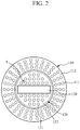
- FIGS. 2 and 3 are views for describing an example of operating the HIFU treatment device shown in FIG.1 .
- HIFU high-intensity focused ultrasonic wave
- a HIFU treatment device 100 includes a first HIFU transducer 110, a second HIFU transducer 120, an imaging transducer 130, a rotation driving part 140, and a controller 150.
- the first HIFU transducer 110 is configured to emit HIFUs for treating a patient.
- An insertion hole 114 is formed in the center of the first HIFU transducer 110.
- the first HIFU transducer 110 may include a plurality of first high-intensity ultrasonic wave vibrators 111 and a first high-intensity ultrasonic wave emitting surface 112.
- the first high-intensity ultrasonic wave vibrators 111 generate high-intensity ultrasonic waves.
- the first high-intensity ultrasonic wave vibrators 111 may be installed on the first high-intensity ultrasonic wave emitting surface 112 by being arranged thereon.
- the first high-intensity ultrasonic wave vibrators 111 may each include piezoelectric elements. The piezoelectric elements may resonate to generate ultrasonic waves when receiving a voltage from the controller 150.
- the first HIFU transducer 110 is implemented as a phased array transducer having a number of channels corresponding to the number of the first high-intensity ultrasonic wave vibrators 111.
- the first high-intensity ultrasonic wave emitting surface 112 focuses high-intensity ultrasonic waves generated by the first high-intensity ultrasonic wave vibrators 111.
- the first high-intensity ultrasonic wave emitting surface 112 may be formed at a lower portion of a first support frame 113.
- the first support frame 113 may take the form of a circular plate.
- the insertion hole 114 may be provided at a center of the first support frame 113 in a circular shape.
- the first support frame 113 may be accommodated and fixed in a housing (not shown) having an open bottom side. Alternatively, the first support frame 113 may take the form of a hemisphere that is upwardly concave.
- the second HIFU transducer 120 is configured to emit HIFUs.
- the second HIFU transducer 120 is inserted into the insertion hole 114 of the first HIFU transducer 110 and rotates. Accordingly, the second HIFU transducer 120 rotates inside of the first HIFU transducer 110.
- the imaging transducer 130 is installed on the second HIFU transducer 120.
- the second HIFU transducer 120 may include a plurality of second high-intensity ultrasonic wave vibrators 121 and a second high-intensity ultrasonic wave emitting surface 122.
- the second high-intensity ultrasonic wave vibrators 121 generate high-intensity ultrasonic waves.
- the second high-intensity ultrasonic wave vibrators 121 may be implemented in the same manner as the first high-intensity ultrasonic wave vibrators 111.
- the second high-intensity ultrasonic wave vibrators 121 may be installed on the second high-intensity ultrasonic wave emitting surface 122 by being arranged around the imaging transducer 130.
- the second HIFU transducer 120 is also implemented as a phased array transducer having a number of channels corresponding to the number of the second high-intensity ultrasonic wave vibrators 121.
- the controller 150 controls phases of ultrasonic waves generated by the first and second high-intensity ultrasonic wave vibrators 111 and 121 to freely adjust a propagation direction and a focal distance of the ultrasonic waves. Accordingly, a focal position of HIFUs of the first and second HIFU transducers 110 and 120 may be adjusted.
- the second high-intensity ultrasonic wave emitting surface 122 focuses high-intensity ultrasonic waves generated by the second high-intensity ultrasonic wave vibrators 121.
- the second high-intensity ultrasonic wave emitting surface 122 may be formed at a lower portion of a second support frame 123.
- the first support frame 113 takes the form of a circular plate
- the second support frame 123 may take the form of a circular plate.
- the second support frame 123 may have a size in which the second support frame 123 can be inserted into the insertion hole 114 while being spaced apart from the insertion hole 114 by a predetermined distance.
- the second support frame 123 may be fixed at a lower end of a casing 131 which accommodates the imaging transducer 130.
- the casing 131 may be rotated by the rotation driving part 140.
- the second support frame 123 may also take the form of a hemisphere.
- the first and second high-intensity ultrasonic wave emitting surfaces 112 and 122 may be covered by a membrane. A gap between the membrane and the first and second high-intensity ultrasonic wave emitting surfaces 112 and 122 may be filled with an ultrasonic wave transfer medium.
- the ultrasonic wave transfer medium may include deaerated water. HIFUs emitted by the first and second HIFU transducers 110 and 120 are transmitted to a lesion area of a patient via the ultrasonic wave transfer medium.
- the imaging transducer 130 is provided to obtain an image.
- the imaging transducer 130 rotates together with the second HIFU transducer 120 by being installed on the second HIFU transducer 120.
- the imaging transducer 130 may obtain an image at each rotation position.
- the imaging transducer 130 may be controlled by the controller 150.
- the controller 150 may display the image obtained by the imaging transducer 130 through a display part of the HIFU treatment device 100.
- the imaging transducer 130 may be provided as a one-dimensional array ultrasonic wave transducer having ultrasonic wave elements arranged in a single axis so that a two-dimensional slice image is obtained.
- the ultrasonic wave elements may be implemented as piezoelectric elements.
- the piezoelectric elements resonate to generate an ultrasonic wave signal when receiving an electric signal, and vibrate to generate an electric signal when receiving an ultrasonic wave signal.
- the imaging transducer 130 may be protected by being accommodated in the casing 131.
- the rotation driving part 140 rotates the second HIFU transducer 120.
- the rotation driving part 140 may include a rotation motor.
- the rotation motor may be provided with a body fixed to the housing.
- the rotation motor may be fixed to the casing 131 with a driving shaft thereof positioned at a center of rotation of the second HIFU transducer 120. Accordingly, a rotation of the driving shaft of the rotation motor may rotate the second HIFU transducer 120.
- the controller 150 may control the first and second HIFU transducers 110 and 120, the imaging transducer 130, and the rotation driving part 140. For example, referring to FIGS. 2 and 3 , the controller 150 may control the rotation driving part 140 to rotate the second HIFU transducer 120 relative to the first HIFU transducer 110 so that an image plane of the imaging transducer 130 is aligned with a focal position F of HIFUs.
- the controller 150 may update a position of each channel of the second HIFU transducer 120.
- the position of each channel of the second HIFU transducer 120 may represent a position of each of the second high-intensity ultrasonic wave vibrators 121.
- the controller 150 may calculate and update position coordinates of the respective second high-intensity ultrasonic wave vibrators 121 that are changed according to a rotation angle of the second HIFU transducer 120. Then, the controller 150 may control the first and second HIFU transducers 110 and 120 to focus high-intensity ultrasonic waves on the focal position F.
- coordinates of a center of each channel of the second HIFU transducer 120 which is changed according to a rotation angle of the second HIFU transducer 120 may be calculated and updated according to Equation 1 and Equation 2.
- x and y represent a focal position in an X-axis direction and a focal position in a Y-axis direction, respectively, with respect to an origin positioned at the center of the second HIFU transducer.
- ⁇ represents a rotation angle of the second HIFU transducer.
- Cx and Cy represent coordinates of the center of each channel of the second HIFU transducer before the second HIFU transducer rotates.
- CX and CY represent coordinates of the center of each channel of the second HIFU transducer after the second HIFU transducer rotates by an angle of ⁇ .
- the HIFU treatment device 100 includes not only a radiation area of HIFUs of the first HIFU transducer 110, but also a radiation area of HIFUs of the second HIFU transducer 120 around the imaging transducer 130. Accordingly, the HIFU treatment device 100 has a larger radiation area of HIFUs when compared to the conventional technology. In this manner, since the HIFU treatment device 100 has an improved focal gain of the first and second HIFU transducers 110 and 120, an improved resolution of HIFUs, and a reduced side lobe, the quality of an acoustic field of HIFUs may be improved.
- the imaging transducer 130 Even though an ultrasonic wave transmission/reception portion of the imaging transducer 130 is made to be large, the radiation area of HIFUs is sufficiently secured. Accordingly, since an increased number of ultrasonic wave elements of the imaging transducer 130 may be provided, the image quality is improved by increasing a lateral resolution of an image obtained by the imaging transducer 130.
- FIG. 4 is an XZ image plane obtained by the imaging transducer and displayed on the display part
- FIG. 5 is an XY image plane obtained by the imaging transducer and displayed on the display part.
- an operator may position the HIFU treatment device 100 at a lesion area of a patient.
- the operator may preform a pre-scan on the lesion area of the patient while checking an image obtained by the imaging transducer 130 through the display part.
- the operator may arrange the HIFU treatment device 100 such that the lesion area of the patient is positioned within a high-intensity ultrasonic wave steering range of the first and second HIFU transducers 110 and 120.
- the operator may set the focal position F of HIFUs to suit the lesion area of the patient while checking the image through the display part.
- the operator manipulates an operating part of the HIFU treatment device 100 to input a horizontal line HL to correspond to a lesion area within a high-intensity ultrasonic wave steering range B1 displayed on the XZ image plane so that a focal depth in a Z-axis direction is set.
- the focal depth in the Z-axis direction may be set by inputting the horizontal line HL on a YZ image plane.
- a high-intensity ultrasonic wave steering range B2 at the set focal depth is displayed on the XY image plane.
- the operator manipulates the operating part of the HIFU treatment device 100 to set the focal position F in the X-axis direction and the Y-axis direction within the high-intensity ultrasonic wave steering range B2 of the XY image plane.
- a plurality of focal positions F and F' may be set.
- the controller 150 may automatically make a schedule for sequentially rotating the second HIFU transducer 120 to the focal positions F and F'.
- the operator manipulates the operating part so that the second HIFU transducer 120 is rotated relative to the first HIFU transducer 110.
- the second HIFU transducer 120 is controlled by the controller 150 to be rotated until an image plane of the imaging transducer 130 is aligned with one the focal position F of the focal positions of HIFUs.
- the controller 150 may update the position of each channel of the second HIFU transducer 120 according to a rotation angle of the second HIFU transducer 120.
- a check line CL that moves according to a rotation of the imaging transducer 130 is displayed on the XY image plane shown in FIG. 5 .
- the operator manipulates the operating part to drive the first and second HIFU transducers 110 and 120 while checking the image generated by the imaging transducer 130 through the display part.
- the first and second HIFU transducers 110 and 120 are driven, high-intensity ultrasonic waves are focused on the focal position F.
- the second HIFU transducer 120 is rotated by the controller 150 so that the image plane of the imaging transducer 130 is aligned with the other focal position F'. Then, the operator manipulates the operating part to drive the first and second HIFU transducers 110 and 120 so that high-intensity ultrasonic waves are focused at the other focal position F' while checking the image generated by the imaging transducer 130 through the display part. In the process, the lesion area of the patient is treated by the high-intensity ultrasonic waves.
- FIG. 6 is a perspective view illustrating a HIFU treatment device according to a second exemplary embodiment of the present invention.
- FIG. 7 is an exploded perspective view of FIG. 6 .
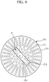
- FIGS. 8 and 9 are views for describing an example of operating the HIFU treatment device shown in FIG.6 .
- a HIFU treatment device 200 includes a HIFU transducer 210, an imaging transducer 220, a rotation driving part 230, and a controller 240.
- the HIFU transducer 210 is configured to emit HIFUs.
- the HIFU transducer 210 may include a plurality of high-intensity ultrasonic wave vibrators 211 and a high-intensity ultrasonic wave emitting surface 212.
- the high-intensity ultrasonic wave vibrators 211 generate high-intensity ultrasonic waves.
- the high-intensity ultrasonic wave vibrators 211 are installed on the high-intensity ultrasonic wave emitting surface 212 by being arranged thereon. Some of the high-intensity ultrasonic wave vibrators 211 are disposed to overlap the imaging transducer 220.
- the HIFU transducer 210 is implemented as a phased array transducer having a number of channels corresponding to the number of the high-intensity ultrasonic wave vibrators 211.
- the high-intensity ultrasonic wave emitting surface 212 focuses high-intensity ultrasonic waves generated by the high-intensity ultrasonic wave vibrators 211.
- the high-intensity ultrasonic wave emitting surface 212 is formed at a lower portion of a support frame 213.
- the support frame 213 takes the form of a circular plate.
- a shaft hole through which a rotary shaft 221 of the imaging transducer 220 passes is formed at a center of the support frame 213.
- the support frame 213 may take the form of a hemisphere that is upwardly concave.
- the imaging transducer 220 is provided to obtain an image.
- the imaging transducer 220 may be provided as a one-dimensional array ultrasonic wave transducer to obtain a two-dimensional slice image.
- the imaging transducer 220 rotates with one portion thereof overlapping an ultrasonic wave emitting portion of the HIFU transducer 210 at the center of the HIFU transducer 210.
- the imaging transducer 220 may rotate while facing the high-intensity ultrasonic wave emitting surface 212 of the HIFU transducer 210.
- the rotation driving part 230 rotates the imaging transducer 220.
- the rotation driving part 230 may include a rotation motor.
- the rotation motor may have a driving shaft thereof fixed to the rotary shaft 221 of the imaging transducer 220 so that a rotation of the rotation motor may rotate the imaging transducer 220.
- the controller 240 may control the HIFU transducer 210, the imaging transducer 220, and the rotation driving part 230.
- the controller 240 may control the rotation driving part 230 to rotate the imaging transducer 220 relative to the HIFU transducer 210 so that an image plane of the imaging transducer 220 is aligned with a focal position of HIFUs.
- the controller 240 turns off some channels overlapping the imaging transducer 220 among the channels of the HIFU transducer 210 and turns on the remaining channels to focus high-intensity ultrasonic waves on the focal position.
- the position of each channel of the HIFU transducer 210 may represent a position of each of the high-intensity ultrasonic wave vibrators 211.
- the controller 240 may identify positions of some of the high-intensity ultrasonic wave vibrators 211 which overlap the imaging transducer 220 according to a rotation angle of the imaging transducer 220 and turn off the high-intensity ultrasonic wave vibrators 211 having the identified positions. Accordingly, not only the imaging transducer 220 but also the high-intensity ultrasonic wave vibrators 211 overlapping the imaging transducer 220 are prevented from being damaged during the driving of the HIFU transducer 210.
- the HIFU treatment device 200 may improve the quality of an acoustic field of HIFUs by having a larger radiation area of HIFUs.
- an increased number of ultrasonic wave elements of the imaging transducer 220 may be provided so that image quality is improved by increasing a lateral resolution of an image obtained by the imaging transducer 220.
- a method for controlling the HIFU treatment device 200 will be described with reference to FIGS. 6 to 9 .
- an operator may position the HIFU treatment device 200 at a lesion area of a patient.
- the operator may perform a pre-scan on the lesion area of the patient while checking an image obtained by the imaging transducer 220 through a display part.
- the operator may arrange the HIFU treatment device 200 so that the lesion area of the patient is positioned within a high-intensity ultrasonic wave steering range of the HIFU transducer 210.
- the operator may manipulate an operating part of the HIFU treatment device 200 to set the focal position F of HIFUs to suit the lesion area of the patent while checking the image through the display part. Then, the operator manipulates the operating part so that the imaging transducer 220 is rotated relative to the HIFU transducer 210. In this case, the imaging transducer 220 is controlled to be rotated until an image plane of the imaging transducer 220 is aligned with the focal position F of HIFUs. In the process, the controller 240 may identify positions of channels of the HIFU transducer 210 which overlap the imaging transducer 220 according to a rotation angle of the imaging transducer 220.
- the operator drives the HIFU transducer 210 by manipulating the operating part while checking the image generated by the imaging transducer 220 through the display part.
- the controller 240 turns off some channels overlapping the imaging transducer 220 among the channels of the HIFU transducer 210 and turns on the remaining channels.
- high-intensity ultrasonic waves are focused on the focal position F so that the lesion area of the patient is treated.
Landscapes
- Health & Medical Sciences (AREA)
- Life Sciences & Earth Sciences (AREA)
- Biomedical Technology (AREA)
- Public Health (AREA)
- Nuclear Medicine, Radiotherapy & Molecular Imaging (AREA)
- Veterinary Medicine (AREA)
- Radiology & Medical Imaging (AREA)
- Engineering & Computer Science (AREA)
- General Health & Medical Sciences (AREA)
- Animal Behavior & Ethology (AREA)
- Medical Informatics (AREA)
- Molecular Biology (AREA)
- Surgery (AREA)
- Heart & Thoracic Surgery (AREA)
- Physics & Mathematics (AREA)
- Biophysics (AREA)
- Pathology (AREA)
- Gynecology & Obstetrics (AREA)
- Surgical Instruments (AREA)
Claims (8)
- Dispositif de traitement (100) par ondes ultrasonores focalisées à haute intensité (HIFU) comprenant :un premier transducteur d'HIFU (110) configuré pour émettre des HIFU, et ayant un trou d'insertion (114) formé en son centre ;un second transducteur d'HIFU (120) configuré pour émettre des HIFU et pour être inséré dans le trou d'insertion du premier transducteur d'HIFU et tourner dans celui-ci ;un transducteur d'imagerie (130) installé sur le second transducteur d'HIFU pour tourner conjointement avec le second transducteur d'HIFU et configuré pour obtenir une image ;une partie d'entraînement en rotation (140) configurée pour faire tourner le second transducteur d'HIFU ; etun dispositif de commande (150) configuré pour commander les premier et second transducteurs d'HIFU (110, 120), le transducteur d'imagerie (130), et la partie d'entraînement en rotation (140).
- Dispositif de traitement par HIFU selon la revendication 1, dans lequel le dispositif de commande (150) commande la partie d'entraînement en rotation (140) pour faire tourner le second transducteur d'HIFU (120) par rapport au premier transducteur d'HIFU (110) de sorte qu'un plan d'image du transducteur d'imagerie (130) soit aligné avec une position focale (F) des HIFU.
- Dispositif de traitement par HIFU selon la revendication 2, dans lequel le dispositif de commande (110) actualise une position de chaque canal du second transducteur d'HIFU (120) lorsque le plan d'image du transducteur d'imagerie (130) est aligné avec la position focale des HIFU, et commande ensuite les premier et second transducteurs d'HIFU (110, 120) de sorte que des ondes ultrasonores de haute intensité soient focalisées sur la position focale (F),
dans lequel chaque canal du second transducteur d'HIFU (120) correspond à un second vibrateur à ondes ultrasonores focalisées à haute intensité respectif (121). - Dispositif de traitement par HIFU selon la revendication 1, dans lequel les premier et second transducteurs d'HIFU (110, 120) sont des transducteurs de réseau en phase.
- Dispositif de traitement par HIFU selon la revendication 1, dans lequel le transducteur d'imagerie (130) est fourni sous la forme d'un transducteur d'ondes ultrasonores d'un réseau monodimensionnel ayant des éléments d'ondes ultrasonores agencés dans un axe unique.
- Dispositif de traitement (200) par ondes ultrasonores focalisées à haute intensité (HIFU) comprenant :un transducteur d'HIFU (210) configuré pour émettre des HIFU ;un transducteur d'imagerie (220) configuré pour obtenir une image et pour tourner avec une portion de celui-ci chevauchant une portion émettant des ondes ultrasonores du transducteur d'HIFU (210) à un centre du transducteur d'HIFU ;une partie d'entraînement en rotation (230) configurée pour faire tourner le transducteur d'imagerie (220) ; etun dispositif de commande (240) configuré pour commander le transducteur d'HIFU (210), le transducteur d'imagerie (220), et la partie d'entraînement en rotation (230), caractérisé en ce que :le dispositif de commande (240) commande la partie d'entraînement en rotation (230) pour faire tourner le transducteur d'imagerie (220) par rapport au transducteur d'HIFU (210) de sorte qu'un plan d'image du transducteur d'imagerie (220) soit aligné avec une position focale (F) des HIFU obtenue par le transducteur d'HIFU (210), etle dispositif de commande (240) désactive des canaux du transducteur d'HIFU (210) chevauchant le transducteur d'imagerie (220) et active des canaux restants du transducteur d'HIFU (210) pour focaliser des ondes ultrasonores à haute intensité sur la position focale (F) lorsque le plan d'image du transducteur d'imagerie (220) est aligné avec la position focale des HIFU,dans lequel les canaux du transducteur d'HIFU (210) correspondent à des vibrateurs d'ondes ultrasonores à haute intensité (211).
- Dispositif de traitement par HIFU selon la revendication 6, dans lequel le transducteur d'HIFU (210) est un transducteur de réseau en phase.
- Dispositif de traitement par HIFU selon la revendication 6, dans lequel le transducteur d'imagerie (210) est fourni sous la forme d'un transducteur d'ondes ultrasonores d'un réseau monodimensionnel ayant des éléments d'ondes ultrasonores agencés dans un axe unique.
Applications Claiming Priority (2)
| Application Number | Priority Date | Filing Date | Title |
|---|---|---|---|
| KR1020140010666A KR101533402B1 (ko) | 2014-01-28 | 2014-01-28 | 고강도 집속 초음파 치료기 및 그 제어방법 |
| PCT/KR2014/000841 WO2015115683A1 (fr) | 2014-01-28 | 2014-01-29 | Dispositif de traitement par ondes ultrasonores focalisées à haute intensité et son procédé de commande |
Publications (3)
| Publication Number | Publication Date |
|---|---|
| EP3100767A1 EP3100767A1 (fr) | 2016-12-07 |
| EP3100767A4 EP3100767A4 (fr) | 2017-02-01 |
| EP3100767B1 true EP3100767B1 (fr) | 2019-11-20 |
Family
ID=53757245
Family Applications (1)
| Application Number | Title | Priority Date | Filing Date |
|---|---|---|---|
| EP14880395.0A Active EP3100767B1 (fr) | 2014-01-28 | 2014-01-29 | Dispositif de traitement par ondes ultrasonores focalisées à haute intensité et son procédé de commande |
Country Status (3)
| Country | Link |
|---|---|
| EP (1) | EP3100767B1 (fr) |
| KR (1) | KR101533402B1 (fr) |
| WO (1) | WO2015115683A1 (fr) |
Cited By (2)
| Publication number | Priority date | Publication date | Assignee | Title |
|---|---|---|---|---|
| EP4469152A4 (fr) * | 2022-01-24 | 2026-01-07 | Histosonics Inc | Systèmes et procédés d'histotripsie |
| US12582848B2 (en) | 2021-06-07 | 2026-03-24 | The Regents Of The University Of Michigan | Minimally invasive histotripsy systems and methods |
Families Citing this family (13)
| Publication number | Priority date | Publication date | Assignee | Title |
|---|---|---|---|---|
| KR101935375B1 (ko) * | 2016-02-01 | 2019-01-07 | 서강대학교산학협력단 | Hifu와 초음파 영상을 위한 초음파 치료 장치 및 그 제어 방법 |
| US11406848B2 (en) | 2016-06-28 | 2022-08-09 | Sogang University Research Foundation | Ultrasonic therapy device using HIFU and control method thereof |
| WO2018098091A1 (fr) * | 2016-11-22 | 2018-05-31 | Cedars-Sinai Medical Center | Nouveau dispositif d'administration de médicament et de transfection |
| CN107693963B (zh) * | 2017-09-08 | 2019-07-30 | 青岛尤尼科技有限公司 | 超声波治疗头和超声波治疗头控制方法 |
| KR102124422B1 (ko) | 2018-06-05 | 2020-06-18 | 한국과학기술연구원 | 고강도-저강도 집속초음파 치료장치 |
| KR102335321B1 (ko) | 2019-12-10 | 2021-12-08 | 한국과학기술연구원 | 탈부착 가능한 회로보드를 이용하여 복수의 기능들을 구현하는 초음파 치료 및 진단 장치 |
| KR102507060B1 (ko) | 2021-01-04 | 2023-03-07 | 전남대학교산학협력단 | 초음파 기반 마이크로 파티클 트래핑 및 자극장치 |
| KR102410514B1 (ko) * | 2021-12-15 | 2022-06-22 | 한국솔타(주) | 다초점 체외 충격파 치료기 |
| KR102536179B1 (ko) * | 2022-06-02 | 2023-05-26 | 이상구 | 초음파 장치, 초음파 트랜스듀서 모듈의 제어 방법 |
| CN115957455A (zh) * | 2022-10-18 | 2023-04-14 | 哈尔滨医科大学 | 组合阵元相控阵换能器 |
| JP7576350B1 (ja) * | 2023-07-21 | 2024-10-31 | ソニア・セラピューティクス株式会社 | Hifu照射装置 |
| KR102700381B1 (ko) | 2023-07-27 | 2024-08-30 | (주)웨버인스트루먼트 | 고강도 집속형초음파(hifu) 4세대형 선형포커스 제어장치 |
| KR102948669B1 (ko) * | 2023-11-30 | 2026-04-10 | (주)클래시스 | 회전식 초음파 트랜스듀서를 구비한 초음파 발생장치 및 이를 포함하는 초음파 치료용 핸드피스 |
Family Cites Families (11)
| Publication number | Priority date | Publication date | Assignee | Title |
|---|---|---|---|---|
| EP2332614A1 (fr) * | 2009-12-10 | 2011-06-15 | Theraclion SAS | Dispositif de traitement ultrasonore |
| KR20110074326A (ko) * | 2009-12-24 | 2011-06-30 | 주식회사 알디에스코리아 | 고강도 집속 초음파 치료 시스템 |
| US9192790B2 (en) * | 2010-04-14 | 2015-11-24 | Boston Scientific Scimed, Inc. | Focused ultrasonic renal denervation |
| KR101207309B1 (ko) * | 2010-07-23 | 2012-12-03 | 서강대학교산학협력단 | 치료 신호의 초점 위치 확인 및 치료 진척도 평가가 가능한 하이푸 치료 장치 및 방법 |
| EP2600783A4 (fr) * | 2010-08-02 | 2017-05-17 | Guided Therapy Systems, L.L.C. | Systèmes et procédés de traitement ultrasonore |
| US9573000B2 (en) * | 2010-08-18 | 2017-02-21 | Mirabilis Medica Inc. | HIFU applicator |
| KR101644011B1 (ko) * | 2011-02-01 | 2016-08-01 | 주식회사 하이로닉 | 듀얼 트랜스듀서를 채용한 고강도 집속형 초음파 의료장치 |
| KR20120091737A (ko) * | 2011-02-10 | 2012-08-20 | 주식회사 테라노바 | 초음파 프로브 구조 |
| KR20120100049A (ko) * | 2011-03-02 | 2012-09-12 | 주식회사 하이로닉 | 듀얼 트랜스듀서 초음파변환기 이송장치 |
| ES2587841T3 (es) * | 2011-04-05 | 2016-10-27 | Inserm - Institut National De La Santé Et De La Recherche Médicale | Dispositivo transesofágico usando ultrasonido focalizado de alta densidad para ablación térmica cardíaca |
| KR101355532B1 (ko) * | 2011-11-21 | 2014-01-24 | 알피니언메디칼시스템 주식회사 | 고강도 집속 초음파용 트랜스듀서 |
-
2014
- 2014-01-28 KR KR1020140010666A patent/KR101533402B1/ko active Active
- 2014-01-29 WO PCT/KR2014/000841 patent/WO2015115683A1/fr not_active Ceased
- 2014-01-29 EP EP14880395.0A patent/EP3100767B1/fr active Active
Non-Patent Citations (1)
| Title |
|---|
| None * |
Cited By (2)
| Publication number | Priority date | Publication date | Assignee | Title |
|---|---|---|---|---|
| US12582848B2 (en) | 2021-06-07 | 2026-03-24 | The Regents Of The University Of Michigan | Minimally invasive histotripsy systems and methods |
| EP4469152A4 (fr) * | 2022-01-24 | 2026-01-07 | Histosonics Inc | Systèmes et procédés d'histotripsie |
Also Published As
| Publication number | Publication date |
|---|---|
| KR101533402B1 (ko) | 2015-07-03 |
| EP3100767A4 (fr) | 2017-02-01 |
| EP3100767A1 (fr) | 2016-12-07 |
| WO2015115683A1 (fr) | 2015-08-06 |
Similar Documents
| Publication | Publication Date | Title |
|---|---|---|
| EP3100767B1 (fr) | Dispositif de traitement par ondes ultrasonores focalisées à haute intensité et son procédé de commande | |
| EP2470267B1 (fr) | Bras de commande de micromanipulateur pour transducteurs thérapeutiques et d'imagerie du type à ultrasons | |
| US10843012B2 (en) | Optimized therapeutic energy delivery | |
| JP4322322B2 (ja) | 超音波治療装置 | |
| KR20190004701A (ko) | 초음파 이미징 및 치료 디바이스 | |
| JP2002209905A (ja) | 超音波治療プローブ及び超音波治療装置 | |
| JPH06315482A (ja) | 音波により生体の身体における領域を位置検出して処置する治療装置 | |
| CN102781516A (zh) | 超声治疗设备 | |
| JP2001046387A (ja) | 超音波治療アプリケータ | |
| JP7605906B2 (ja) | トランスフェクションおよび薬剤送達用の新規デバイス | |
| JP4434668B2 (ja) | 治療システム及び治療支援システム | |
| JP2007160093A (ja) | 高強度焦点超音波システム及び高強度焦点超音波システム用結合ヘッド | |
| JPH0824268A (ja) | 衝撃波治療装置及び温熱治療装置 | |
| JP4782407B2 (ja) | 超音波照射装置 | |
| JP2013153998A (ja) | 超音波治療システム | |
| JP2004073697A (ja) | 超音波照射装置 | |
| JP7576350B1 (ja) | Hifu照射装置 | |
| JPH08164135A (ja) | 強力超音波ビーム照射方法及びその方法に使用する超音波照射治療装置 | |
| KR102486573B1 (ko) | 뇌 질환용 초음파 영상 장치 및 이를 이용한 초음파 이미징 방법 | |
| JP2015146952A (ja) | 超音波治療装置及び超音波治療システム | |
| JPH04272751A (ja) | 超音波治療装置 | |
| WO2018154717A1 (fr) | Dispositif d'endoscope à ultrasons | |
| JPH0779990A (ja) | 超音波治療装置 | |
| HK40008492A (en) | A novel transfection and drug delivery device | |
| JPH02295554A (ja) | 衝撃波治療装置及び温熱治療装置 |
Legal Events
| Date | Code | Title | Description |
|---|---|---|---|
| PUAI | Public reference made under article 153(3) epc to a published international application that has entered the european phase |
Free format text: ORIGINAL CODE: 0009012 |
|
| STAA | Information on the status of an ep patent application or granted ep patent |
Free format text: STATUS: REQUEST FOR EXAMINATION WAS MADE |
|
| 17P | Request for examination filed |
Effective date: 20160823 |
|
| AK | Designated contracting states |
Kind code of ref document: A1 Designated state(s): AL AT BE BG CH CY CZ DE DK EE ES FI FR GB GR HR HU IE IS IT LI LT LU LV MC MK MT NL NO PL PT RO RS SE SI SK SM TR |
|
| AX | Request for extension of the european patent |
Extension state: BA ME |
|
| A4 | Supplementary search report drawn up and despatched |
Effective date: 20170105 |
|
| RIC1 | Information provided on ipc code assigned before grant |
Ipc: A61B 8/00 20060101ALI20161223BHEP Ipc: A61N 7/02 20060101AFI20161223BHEP |
|
| DAX | Request for extension of the european patent (deleted) | ||
| GRAP | Despatch of communication of intention to grant a patent |
Free format text: ORIGINAL CODE: EPIDOSNIGR1 |
|
| STAA | Information on the status of an ep patent application or granted ep patent |
Free format text: STATUS: GRANT OF PATENT IS INTENDED |
|
| INTG | Intention to grant announced |
Effective date: 20190603 |
|
| GRAS | Grant fee paid |
Free format text: ORIGINAL CODE: EPIDOSNIGR3 |
|
| GRAA | (expected) grant |
Free format text: ORIGINAL CODE: 0009210 |
|
| STAA | Information on the status of an ep patent application or granted ep patent |
Free format text: STATUS: THE PATENT HAS BEEN GRANTED |
|
| AK | Designated contracting states |
Kind code of ref document: B1 Designated state(s): AL AT BE BG CH CY CZ DE DK EE ES FI FR GB GR HR HU IE IS IT LI LT LU LV MC MK MT NL NO PL PT RO RS SE SI SK SM TR |
|
| REG | Reference to a national code |
Ref country code: GB Ref legal event code: FG4D |
|
| REG | Reference to a national code |
Ref country code: CH Ref legal event code: EP |
|
| REG | Reference to a national code |
Ref country code: DE Ref legal event code: R096 Ref document number: 602014057312 Country of ref document: DE |
|
| REG | Reference to a national code |
Ref country code: IE Ref legal event code: FG4D |
|
| REG | Reference to a national code |
Ref country code: AT Ref legal event code: REF Ref document number: 1203522 Country of ref document: AT Kind code of ref document: T Effective date: 20191215 |
|
| REG | Reference to a national code |
Ref country code: NL Ref legal event code: MP Effective date: 20191120 |
|
| REG | Reference to a national code |
Ref country code: LT Ref legal event code: MG4D |
|
| PG25 | Lapsed in a contracting state [announced via postgrant information from national office to epo] |
Ref country code: GR Free format text: LAPSE BECAUSE OF FAILURE TO SUBMIT A TRANSLATION OF THE DESCRIPTION OR TO PAY THE FEE WITHIN THE PRESCRIBED TIME-LIMIT Effective date: 20200221 Ref country code: LT Free format text: LAPSE BECAUSE OF FAILURE TO SUBMIT A TRANSLATION OF THE DESCRIPTION OR TO PAY THE FEE WITHIN THE PRESCRIBED TIME-LIMIT Effective date: 20191120 Ref country code: NL Free format text: LAPSE BECAUSE OF FAILURE TO SUBMIT A TRANSLATION OF THE DESCRIPTION OR TO PAY THE FEE WITHIN THE PRESCRIBED TIME-LIMIT Effective date: 20191120 Ref country code: SE Free format text: LAPSE BECAUSE OF FAILURE TO SUBMIT A TRANSLATION OF THE DESCRIPTION OR TO PAY THE FEE WITHIN THE PRESCRIBED TIME-LIMIT Effective date: 20191120 Ref country code: LV Free format text: LAPSE BECAUSE OF FAILURE TO SUBMIT A TRANSLATION OF THE DESCRIPTION OR TO PAY THE FEE WITHIN THE PRESCRIBED TIME-LIMIT Effective date: 20191120 Ref country code: NO Free format text: LAPSE BECAUSE OF FAILURE TO SUBMIT A TRANSLATION OF THE DESCRIPTION OR TO PAY THE FEE WITHIN THE PRESCRIBED TIME-LIMIT Effective date: 20200220 Ref country code: BG Free format text: LAPSE BECAUSE OF FAILURE TO SUBMIT A TRANSLATION OF THE DESCRIPTION OR TO PAY THE FEE WITHIN THE PRESCRIBED TIME-LIMIT Effective date: 20200220 Ref country code: FI Free format text: LAPSE BECAUSE OF FAILURE TO SUBMIT A TRANSLATION OF THE DESCRIPTION OR TO PAY THE FEE WITHIN THE PRESCRIBED TIME-LIMIT Effective date: 20191120 |
|
| PG25 | Lapsed in a contracting state [announced via postgrant information from national office to epo] |
Ref country code: RS Free format text: LAPSE BECAUSE OF FAILURE TO SUBMIT A TRANSLATION OF THE DESCRIPTION OR TO PAY THE FEE WITHIN THE PRESCRIBED TIME-LIMIT Effective date: 20191120 Ref country code: IS Free format text: LAPSE BECAUSE OF FAILURE TO SUBMIT A TRANSLATION OF THE DESCRIPTION OR TO PAY THE FEE WITHIN THE PRESCRIBED TIME-LIMIT Effective date: 20200320 Ref country code: HR Free format text: LAPSE BECAUSE OF FAILURE TO SUBMIT A TRANSLATION OF THE DESCRIPTION OR TO PAY THE FEE WITHIN THE PRESCRIBED TIME-LIMIT Effective date: 20191120 |
|
| PG25 | Lapsed in a contracting state [announced via postgrant information from national office to epo] |
Ref country code: AL Free format text: LAPSE BECAUSE OF FAILURE TO SUBMIT A TRANSLATION OF THE DESCRIPTION OR TO PAY THE FEE WITHIN THE PRESCRIBED TIME-LIMIT Effective date: 20191120 |
|
| PG25 | Lapsed in a contracting state [announced via postgrant information from national office to epo] |
Ref country code: EE Free format text: LAPSE BECAUSE OF FAILURE TO SUBMIT A TRANSLATION OF THE DESCRIPTION OR TO PAY THE FEE WITHIN THE PRESCRIBED TIME-LIMIT Effective date: 20191120 Ref country code: PT Free format text: LAPSE BECAUSE OF FAILURE TO SUBMIT A TRANSLATION OF THE DESCRIPTION OR TO PAY THE FEE WITHIN THE PRESCRIBED TIME-LIMIT Effective date: 20200412 Ref country code: DK Free format text: LAPSE BECAUSE OF FAILURE TO SUBMIT A TRANSLATION OF THE DESCRIPTION OR TO PAY THE FEE WITHIN THE PRESCRIBED TIME-LIMIT Effective date: 20191120 Ref country code: ES Free format text: LAPSE BECAUSE OF FAILURE TO SUBMIT A TRANSLATION OF THE DESCRIPTION OR TO PAY THE FEE WITHIN THE PRESCRIBED TIME-LIMIT Effective date: 20191120 Ref country code: CZ Free format text: LAPSE BECAUSE OF FAILURE TO SUBMIT A TRANSLATION OF THE DESCRIPTION OR TO PAY THE FEE WITHIN THE PRESCRIBED TIME-LIMIT Effective date: 20191120 Ref country code: RO Free format text: LAPSE BECAUSE OF FAILURE TO SUBMIT A TRANSLATION OF THE DESCRIPTION OR TO PAY THE FEE WITHIN THE PRESCRIBED TIME-LIMIT Effective date: 20191120 |
|
| REG | Reference to a national code |
Ref country code: AT Ref legal event code: MK05 Ref document number: 1203522 Country of ref document: AT Kind code of ref document: T Effective date: 20191120 |
|
| REG | Reference to a national code |
Ref country code: DE Ref legal event code: R097 Ref document number: 602014057312 Country of ref document: DE |
|
| PG25 | Lapsed in a contracting state [announced via postgrant information from national office to epo] |
Ref country code: SM Free format text: LAPSE BECAUSE OF FAILURE TO SUBMIT A TRANSLATION OF THE DESCRIPTION OR TO PAY THE FEE WITHIN THE PRESCRIBED TIME-LIMIT Effective date: 20191120 Ref country code: MC Free format text: LAPSE BECAUSE OF FAILURE TO SUBMIT A TRANSLATION OF THE DESCRIPTION OR TO PAY THE FEE WITHIN THE PRESCRIBED TIME-LIMIT Effective date: 20191120 Ref country code: SK Free format text: LAPSE BECAUSE OF FAILURE TO SUBMIT A TRANSLATION OF THE DESCRIPTION OR TO PAY THE FEE WITHIN THE PRESCRIBED TIME-LIMIT Effective date: 20191120 |
|
| REG | Reference to a national code |
Ref country code: CH Ref legal event code: PL |
|
| PLBE | No opposition filed within time limit |
Free format text: ORIGINAL CODE: 0009261 |
|
| STAA | Information on the status of an ep patent application or granted ep patent |
Free format text: STATUS: NO OPPOSITION FILED WITHIN TIME LIMIT |
|
| REG | Reference to a national code |
Ref country code: BE Ref legal event code: MM Effective date: 20200131 |
|
| 26N | No opposition filed |
Effective date: 20200821 |
|
| GBPC | Gb: european patent ceased through non-payment of renewal fee |
Effective date: 20200220 |
|
| PG25 | Lapsed in a contracting state [announced via postgrant information from national office to epo] |
Ref country code: LU Free format text: LAPSE BECAUSE OF NON-PAYMENT OF DUE FEES Effective date: 20200129 |
|
| PG25 | Lapsed in a contracting state [announced via postgrant information from national office to epo] |
Ref country code: PL Free format text: LAPSE BECAUSE OF FAILURE TO SUBMIT A TRANSLATION OF THE DESCRIPTION OR TO PAY THE FEE WITHIN THE PRESCRIBED TIME-LIMIT Effective date: 20191120 Ref country code: SI Free format text: LAPSE BECAUSE OF FAILURE TO SUBMIT A TRANSLATION OF THE DESCRIPTION OR TO PAY THE FEE WITHIN THE PRESCRIBED TIME-LIMIT Effective date: 20191120 Ref country code: BE Free format text: LAPSE BECAUSE OF NON-PAYMENT OF DUE FEES Effective date: 20200131 Ref country code: CH Free format text: LAPSE BECAUSE OF NON-PAYMENT OF DUE FEES Effective date: 20200131 Ref country code: AT Free format text: LAPSE BECAUSE OF FAILURE TO SUBMIT A TRANSLATION OF THE DESCRIPTION OR TO PAY THE FEE WITHIN THE PRESCRIBED TIME-LIMIT Effective date: 20191120 Ref country code: LI Free format text: LAPSE BECAUSE OF NON-PAYMENT OF DUE FEES Effective date: 20200131 |
|
| PG25 | Lapsed in a contracting state [announced via postgrant information from national office to epo] |
Ref country code: IT Free format text: LAPSE BECAUSE OF FAILURE TO SUBMIT A TRANSLATION OF THE DESCRIPTION OR TO PAY THE FEE WITHIN THE PRESCRIBED TIME-LIMIT Effective date: 20191120 Ref country code: GB Free format text: LAPSE BECAUSE OF NON-PAYMENT OF DUE FEES Effective date: 20200220 Ref country code: IE Free format text: LAPSE BECAUSE OF NON-PAYMENT OF DUE FEES Effective date: 20200129 |
|
| PG25 | Lapsed in a contracting state [announced via postgrant information from national office to epo] |
Ref country code: TR Free format text: LAPSE BECAUSE OF FAILURE TO SUBMIT A TRANSLATION OF THE DESCRIPTION OR TO PAY THE FEE WITHIN THE PRESCRIBED TIME-LIMIT Effective date: 20191120 Ref country code: MT Free format text: LAPSE BECAUSE OF FAILURE TO SUBMIT A TRANSLATION OF THE DESCRIPTION OR TO PAY THE FEE WITHIN THE PRESCRIBED TIME-LIMIT Effective date: 20191120 Ref country code: CY Free format text: LAPSE BECAUSE OF FAILURE TO SUBMIT A TRANSLATION OF THE DESCRIPTION OR TO PAY THE FEE WITHIN THE PRESCRIBED TIME-LIMIT Effective date: 20191120 |
|
| PG25 | Lapsed in a contracting state [announced via postgrant information from national office to epo] |
Ref country code: MK Free format text: LAPSE BECAUSE OF FAILURE TO SUBMIT A TRANSLATION OF THE DESCRIPTION OR TO PAY THE FEE WITHIN THE PRESCRIBED TIME-LIMIT Effective date: 20191120 |
|
| PGFP | Annual fee paid to national office [announced via postgrant information from national office to epo] |
Ref country code: DE Payment date: 20260122 Year of fee payment: 13 |
|
| PGFP | Annual fee paid to national office [announced via postgrant information from national office to epo] |
Ref country code: FR Payment date: 20260120 Year of fee payment: 13 |