EP3101192A1 - Element de paroi de separation - Google Patents
Element de paroi de separation Download PDFInfo
- Publication number
- EP3101192A1 EP3101192A1 EP16172304.4A EP16172304A EP3101192A1 EP 3101192 A1 EP3101192 A1 EP 3101192A1 EP 16172304 A EP16172304 A EP 16172304A EP 3101192 A1 EP3101192 A1 EP 3101192A1
- Authority
- EP
- European Patent Office
- Prior art keywords
- diaphragm
- pressure
- profile
- holding means
- partition wall
- Prior art date
- Legal status (The legal status is an assumption and is not a legal conclusion. Google has not performed a legal analysis and makes no representation as to the accuracy of the status listed.)
- Granted
Links
Images


Classifications
-
- E—FIXED CONSTRUCTIONS
- E04—BUILDING
- E04B—GENERAL BUILDING CONSTRUCTIONS; WALLS, e.g. PARTITIONS; ROOFS; FLOORS; CEILINGS; INSULATION OR OTHER PROTECTION OF BUILDINGS
- E04B2/00—Walls, e.g. partitions, for buildings; Wall construction with regard to insulation; Connections specially adapted to walls
- E04B2/74—Removable non-load-bearing partitions; Partitions with a free upper edge
- E04B2/82—Removable non-load-bearing partitions; Partitions with a free upper edge characterised by the manner in which edges are connected to the building; Means therefor; Special details of easily-removable partitions as far as related to the connection with other parts of the building
- E04B2/827—Partitions constituted of sliding panels
-
- E—FIXED CONSTRUCTIONS
- E04—BUILDING
- E04B—GENERAL BUILDING CONSTRUCTIONS; WALLS, e.g. PARTITIONS; ROOFS; FLOORS; CEILINGS; INSULATION OR OTHER PROTECTION OF BUILDINGS
- E04B2/00—Walls, e.g. partitions, for buildings; Wall construction with regard to insulation; Connections specially adapted to walls
- E04B2/74—Removable non-load-bearing partitions; Partitions with a free upper edge
- E04B2/82—Removable non-load-bearing partitions; Partitions with a free upper edge characterised by the manner in which edges are connected to the building; Means therefor; Special details of easily-removable partitions as far as related to the connection with other parts of the building
- E04B2/825—Removable non-load-bearing partitions; Partitions with a free upper edge characterised by the manner in which edges are connected to the building; Means therefor; Special details of easily-removable partitions as far as related to the connection with other parts of the building the connection between the floor and the ceiling being achieved without any restraining forces acting in the plane of the partition
-
- E—FIXED CONSTRUCTIONS
- E04—BUILDING
- E04B—GENERAL BUILDING CONSTRUCTIONS; WALLS, e.g. PARTITIONS; ROOFS; FLOORS; CEILINGS; INSULATION OR OTHER PROTECTION OF BUILDINGS
- E04B2/00—Walls, e.g. partitions, for buildings; Wall construction with regard to insulation; Connections specially adapted to walls
- E04B2/74—Removable non-load-bearing partitions; Partitions with a free upper edge
- E04B2/82—Removable non-load-bearing partitions; Partitions with a free upper edge characterised by the manner in which edges are connected to the building; Means therefor; Special details of easily-removable partitions as far as related to the connection with other parts of the building
- E04B2/828—Connections between partitions and structural walls
-
- E—FIXED CONSTRUCTIONS
- E06—DOORS, WINDOWS, SHUTTERS, OR ROLLER BLINDS IN GENERAL; LADDERS
- E06B—FIXED OR MOVABLE CLOSURES FOR OPENINGS IN BUILDINGS, VEHICLES, FENCES OR LIKE ENCLOSURES IN GENERAL, e.g. DOORS, WINDOWS, BLINDS, GATES
- E06B3/00—Window sashes, door leaves, or like elements for closing wall or like openings; Layout of fixed or moving closures, e.g. windows in wall or like openings; Features of rigidly-mounted outer frames relating to the mounting of wing frames
- E06B3/32—Arrangements of wings characterised by the manner of movement; Arrangements of movable wings in openings; Features of wings or frames relating solely to the manner of movement of the wing
- E06B3/34—Arrangements of wings characterised by the manner of movement; Arrangements of movable wings in openings; Features of wings or frames relating solely to the manner of movement of the wing with only one kind of movement
- E06B3/42—Sliding wings; Details of frames with respect to guiding
- E06B3/46—Horizontally-sliding wings
- E06B3/4636—Horizontally-sliding wings for doors
Definitions
- the invention relates to a partition wall element for a partition wall system, wherein the partition wall element has a telescoping element extendable in the horizontal direction according to the preamble of patent claim 1.
- the invention also relates to a partition wall system.
- a partition wall system usually comprises a plurality of partition wall elements. Arranged next to one another, the partition wall elements can together form a partition wall.
- an edge-side telescoping element which is extendable by a drive device.
- the telescoping element is horizontally extensible when closing the partition against a fixed building wall or the like to clamp the partition wall elements horizontally against each other and to close the available residual width of the respective building opening gap-free.
- the telescoping is extended against a fixed stop when instead of a fixed building wall another partition or the like connects, which may not be charged with clamping forces.
- the telescopic element In semi-automatic or fully automatic partition systems or partition elements, hereinafter collectively referred to as automatic partition systems or partition elements, usually the telescopic element is provided with safety switches that interrupt the motor drive of Teleskopierelements or other partition element when in contact with an obstacle or switch off. In manually operated partition systems or partition elements can usually be dispensed with such safety switch. This has the consequence that the equipped with the telescoping partition wall element for a manual partition wall system is structurally different designed as equipped with the telescopic partition wall element for automatic partition systems. This leads to an increased complexity in the variety of variants of such partition walls and the resulting high costs.
- the telescoping elements of manual and automatic partition wall elements are usually different from each other in aesthetic appearance due to the corresponding different constructions, which is undesirable in particular in the combination of manual and automatic partition wall elements or partition wall systems in a room.
- a drive device is connected in a complex manner in production with a pressure spar.
- the telescoping element comprises a pressure spar and a diaphragm profile, wherein the diaphragm profile is held in or on the pressure spar, wherein the diaphragm profile comprises at least a first diaphragm holding means, which cooperates with at least one corresponding pressure bar retaining means of the pressure beam.
- the telescoping element comprises, in addition to the pressure spar, an aperture profile which conceals the pressure spar at least partially, preferably completely.
- the diaphragm profile preferably forms at least partially the telescopic side surface of the Partition element.
- the pressure bar can be designed in a simple manner as technically necessary, without having to take into account an aesthetic impression. For example, necessary screwing in the partition element can be made on the pressure spar, which are then covered by the diaphragm profile. By the diaphragm profile is held on the pressure spar, the diaphragm profile is attached to the rest of the telescoping element in a technically simple manner.
- the existing in the telescoping telescoping for pressure bar receives an additional technical function by holding the panel profile. It is particularly advantageous that the diaphragm profile and the pressure bar comprise the necessary holding means. Thus, a particularly aesthetically pleasing design of the side surface of a partition element is achieved in a technically simple manner.
- the diaphragm holding means and the pressure bar retaining means can cooperate positively and / or non-positively.
- the diaphragm holding means and the pressure bar retaining means act positively, d. H. latching together.
- the latching can therefore be designed so that the panel profile is immovably arranged in or on the pressure beam or that the panel profile is movable, in particular with respect to the distance between the pressure beam and panel profile and / or in the vertical direction, is formed.
- room and location information such as "vertical”, “horizontal”, “front”, “rear”, “side”, “telescoping” used as a viewer of a mounted partition system would use the space and location.
- At least two diaphragm retaining means ie a first diaphragm retaining means and a second diaphragm retaining means, are preferably provided, which cooperate in particular latching with at least two pressure strut holding means corresponding thereto.
- features relating to the diaphragm retaining means and / or the pressure bar retaining means also refer to the at least two diaphragm holding means and / or the at least two pressure bar retaining means.
- a partition wall system may comprise one or more partition wall elements, which are arranged movably along a travel path.
- the travel path can in particular be defined by cover-side and / or bottom-side rails, in which the partition wall element or elements are guided.
- the partition elements together can form a partition.
- the partition wall elements can preferably be stowed parallel to one another when the partition wall is dismantled.
- the partition wall elements are arranged close together in a row.
- the partition wall elements are braced by sealing strips, which are extended against the ceiling and / or against the ground.
- a partition wall element according to the invention preferably has rollers for moving in the rail of the partition wall system.
- the partition wall element may comprise cladding panels, by which in particular the predominant part of a front and a back of the partition wall element is formed. A space can be formed between the cladding panels.
- the partition wall element may have at least one sealing strip, preferably two sealing strips for bracing against the ceiling and / or the floor.
- a fully automatic partition wall element the displacement of the partition wall element and the extension of the telescoping element are motorized, while both are performed manually by an operator in a manual partition wall element.
- a semi-automatic partition wall element the partition wall element is moved manually while the telescopic element is extended by a motor.
- the motor extension can be controlled by an electric motor, i. H. electrically, done.
- the telescoping member serves to extend in a horizontal direction.
- the telescoping element can assume a retracted and an extended state.
- a gap which in the retracted state between the partition element and a stationary element, for. B. a building wall, was present, bridged.
- the telescoping element thus forms an end-side connection.
- the telescoping element preferably has cover plates.
- the cover plates may at least partially form the front and the back of the telescoping element.
- the cover plates of the telescoping element overlap with the cladding panels.
- the cover plates enclose the cladding panels.
- the telescoping takes in the retracted state, the cladding panels partially in itself.
- the cover plates can be in the retracted state within the cladding panels.
- the telescoping element is received in the retracted state between the cover plates.
- the pressure spar is used to connect a drive device with the cover plates.
- the drive device serves to extend the telescoping element.
- the drive device may have one or more drive units.
- the pressure bar can extend in the vertical in such a way that the cover plates are extendable.
- the pressure spar extends between 40% and 100%, preferably between 60% and 100%, particularly preferably between 75% and 100%, over the vertical height of the cover plates.
- the pressure spar may have an end face directed towards the side surface of the partition wall element.
- the drive device can be designed to be operated manually or by a motor.
- the diaphragm profile covers at least the end face of the pressure beam.
- the diaphragm profile on the side surface extends approximately or completely over the vertical height of the cover plates. It may be that the aperture profile at the top and / or bottom is formed slightly shorter than the cover plates. Thus, it may be that the cover plates at the top and / or bottom of between 0.1 mm and 20 mm, preferably between 0.1 mm and 10 mm, more preferably between 0.1 mm and 5 mm, formed longer than the diaphragm profile are. This ensures that when tilting the partition wall element, only the soft cover plates and not the diaphragm profile form the tilt.
- the diaphragm profile on the side surface can cover the cover plates in their width.
- the panel profile on the side surface may extend over the entire width and / or substantially over the vertical height of the cover plates.
- the interior of the telescoping element is covered and protected by the diaphragm profile.
- Different technical configurations in the interior of the partition element, the z. B. thereby, whether the partition element and / or the telescoping be moved manually or by motor, are not for the viewer visible, noticeable.
- the side surfaces of automatic and manual partition wall elements and / or partition wall systems despite different constructions in the interior of the Teleskopierelements in the aesthetic appearance of each other. This is particularly desirable in the combination of manual and automatic partition systems in a room.
- the diaphragm profile has a cover element.
- the cover member forms in particular the telescopic side surface.
- the cover preferably extends at least in sections perpendicular to the front or back of the partition element.
- the cover element preferably covers at least the pressure spar.
- the cover is preferably continuous, d. H. open, designed.
- the cover member may be formed with at least one plate-like portion.
- On an outer side of the cover may be an elastic muffler.
- a fastening element for. B. a screw
- the pressure bar can be attached to the drive device in a particularly simple manner.
- the fastening element is preferably concealed by the panel profile. Thus, the aesthetic impression is not disturbed.
- a stop is defined as a position at which the diaphragm holding means and the pressure bar retaining means are positively connected.
- the stop is preferably arranged in the interior of the telescoping element. In particular, the stop is not visible to the viewer of the partition element.
- the diaphragm holding means extends from the cover element inwardly into the telescoping element.
- the diaphragm holding means is located on an inner side of the cover element.
- the diaphragm holding means is integrated in the diaphragm profile in one piece and / or in the same material, in particular monolithic.
- the diaphragm holding means can be integrally and / or materially, in particular monolithic, connected to the cover.
- the pressure strut holding means in one piece and / or material, especially monolithic, in integrated pressure bar. As a result, the pressure bar can be made easy to install.
- the panel profile can be mounted by a horizontal movement on the pressure spar, in particular latched.
- the panel profile can only be mounted, in particular latched, by a horizontal movement on the pressure spar.
- the panel profile is clipped into the pressure spar.
- the panel profile and / or the pressure beam of the partition wall element according to the invention may be suitable both for use in a manual partition wall element as well as an automatic partition wall element, resulting in a significant reduction in complexity for the production and procurement of components for partition systems.
- At least one safety switch is preferably arranged.
- the safety switch is provided to interrupt or switch off the motor drive device of the telescoping element and / or the motor drive of the entire partition element upon contact of the telescoping element with an obstacle.
- a switching pulse is generated for a control of the partition wall element and / or the telescoping element.
- the safety switch is preferably arranged on the end face of the pressure beam.
- the cover profile preferably conceals the safety switch.
- the panel profile can be provided for operating the safety switch.
- the diaphragm holding means and the Druckholhaltesch cooperate such that the diaphragm profile against the Teleskopierides relative to the pressure spar can be arranged movable.
- the diaphragm holding means and the Druckkholmhaltesch counter to the Teleskopierides can be arranged form-fitting manner to each other.
- the diaphragm holding means can be arranged in such a way that it can be arranged by the pressure spar that the safety switch, in particular by a movement of the diaphragm profile against the telescoping direction, can be actuated.
- the shutter profile acts as an actuating means for the safety switch.
- the panel profile can be exempted, in the safety switch is unactuated, and at least one operating position in which the safety switch is actuated and generates a switching pulse for interrupting or switching off the motor drive or the motor drive device occupy.
- the diaphragm profile for actuating the safety switch can be movable via an actuating travel W of 2 mm ⁇ W ⁇ 20 mm, preferably 3 mm ⁇ W ⁇ 15 mm, particularly preferably 4 mm ⁇ W ⁇ 10 mm.
- the diaphragm holding means is reversibly operable. This means that the diaphragm profile between the release and the actuating position is movable back and forth.
- a spring element is arranged between the diaphragm profile and the pressure spar, which acts on the diaphragm profile with a directed away from the pressure beam force.
- the spring element can serve to keep the panel profile, if it is out of contact with the obstacle, in the exemption. Additionally or alternatively, the spring element can serve to move the diaphragm profile from the actuation position into the release position.
- the spring element can move the diaphragm profile into the release position
- the spring element can be attached to the end face of the pressure beam, z. B. screwed, be.
- the spring element is designed in particular as a leaf spring. It can also be distributed over the end face of the pressure beam several spring elements. Preferably, the diaphragm profile covers the spring element or the spring elements.
- a safety switch in particular a microswitch can be provided.
- at least one magnetically actuated switch can be attached, in particular glued, to the inside of the panel profile, in particular on the inside of the cover element.
- a reed switch can serve an obstacle from the end position of the partition element, for. B. on a building wall to distinguish.
- magnets are arranged on or in the building wall, which can interact with the magnetically actuated switch.
- the magnetically actuated switch can override the switching pulse of the safety switch in the vicinity of the end position and so on allow further extension of the telescopic element in the end position. This makes it possible to achieve a sufficiently strong contact pressure for sound insulation and / or for bracing the partition in the end position.
- the diaphragm profile is shaped such that the magnetically actuated switch is not visible to the viewer.
- the same diaphragm profile can also be used for a manually extendable telescoping element.
- the pressure strut holding means and the diaphragm holding means cooperate in such a way that the diaphragm profile is durable, in particular latchable, in a first position in or on the pressure strut, in which in particular a first distance A1 is formed between a first abutment portion of the pressure beam and the diaphragm profile is, and in a second position in or on the pressure spar durable, in particular latched, in which in particular a second distance A2 between a first stop portion of the pressure beam and the blend profile is formed.
- the panel profile can be held in each telescoping direction on the pressure spar.
- the diaphragm profile in a first and in a second position on or in the pressure spar in the telescoping direction can be durable, in particular latched, wherein in the first position, the diaphragm profile occupies a first distance A1 against the Teleskopierides against the pressure spar and in the second position occupies a second distance A2 against the Teleskopierides against the pressure spar.
- the panel profile in the second position can have a greater distance from the pressure spar than in the first position.
- the distance A2 may be greater than the distance A1.
- the diaphragm profile can be substantially fixed to the pressure spar, while at the second distance A2, which in particular in the case of a motor-extendable telescope element and / or or a motor-displaceable partition wall element is present, the diaphragm profile relative to the pressure spar movable, in particular resiliently, be stored.
- the second position may correspond to the exemption.
- the first position does not correspond to the operating position.
- the stopper portion and the diaphragm profile in one of the possible operating positions have a similar or the same first distance A1 relative to the pressure beam as in the first position.
- the diaphragm profile is preferably not held in the telescoping direction on the pressure spar, unlike in the first position.
- the diaphragm profile is fixed in the first position counter to the telescoping direction.
- the diaphragm profile in the first position, is movable only slightly or not at all against the telescoping direction.
- the aperture profile z. B. only less than 2 mm, preferably less than 1 mm, more preferably less than 0.5 mm against the Teleskopieriques be movable.
- the diaphragm profile bears against the telescoping direction on the remaining telescopic element, in particular on the pressure beam and / or on the cover plates.
- the diaphragm profile can be present directly.
- a distal end of the diaphragm retaining means may abut the pressure spar.
- the diaphragm profile and the pressure beam can be actuated via a resilient element, for. B. a sealing tape, abut each other.
- the resilient element can also exert a force on the positive connection of the diaphragm holding means with the pressure spar in the telescoping direction.
- the pressure spar can comprise a first stop section and a second stop section, against which the panel profile, in particular the cover element, preferably with interposition of a respective resilient element, rests.
- the pressure rail and the diaphragm profile in the first position and / or in the actuated position abut each other via at least two resilient elements.
- reaching the first position starting from the second position is prevented by a movement of the diaphragm profile against the telescoping direction. Since in the first position the diaphragm profile is held in the telescoping direction, in particular in a form-locking manner, a movement starting from the second position, ie the release, in the first position is opposed to a reversibility of the switch actuation.
- the diaphragm profile can be arranged in a first mounting position and in a second mounting position on the pressure beam, wherein the diaphragm profile is rotated in the second mounting position about a horizontal axis compared to the first mounting position.
- the diaphragm profile is rotated by 180 ° in this case.
- the first mounting position is provided so that the panel profile assumes the first position
- the second mounting position is provided so that the panel profile occupies the second position.
- the diaphragm profile occupy the first position only in the first mounting position and / or the diaphragm profile, the second position only in the second mounting position.
- the diaphragm profile and / or the pressure beam can be configured asymmetrically with respect to a vertical center plane of the partition wall element.
- the diaphragm holding means with a first pressure strut holding means and in the second mounting position the diaphragm holding means with a further pressure strut holding means, which is asymmetrical in particular to the first pressure strut holding means with respect to the median plane, cooperate.
- At least two stops are provided, on each of which a diaphragm holding means and a pressure strut holding means cooperate, wherein the stops are horizontally spaced apart.
- two stops are provided both in the first position and in the second position.
- a low-wobble arrangement can be achieved both for fully automatic, semi-automatic and manual partition wall elements.
- three stops are provided by the two in the first and in the second position two stops are provided.
- a stop is used both in the first and in the second position.
- the at least two stops can be arranged at the same distance from the vertical center plane of the partition wall element.
- the diaphragm holding means extends in the vertical direction over the diaphragm profile and / or the pressure bar retaining means in the vertical direction over the pressure beam. In this way, the reliability of the partition wall element can be increased because a rotation of the panel profile is prevented relative to the pressure spar.
- the diaphragm holding means and / or the pressure bar retaining means is preferably formed continuously in the vertical direction.
- the diaphragm holding means and / or the pressure bar retaining means may preferably have interruptions at regular intervals. Through these alternatives, it is possible to easily adjust the pressure bar and / or the panel profile to different vertical heights of the cover plates.
- the pressure spar with the pressure strut holding means and / or the diaphragm profile with the diaphragm retaining means are extruded.
- the diaphragm profile is prevented by the resilient element against vertical displacement.
- the panel profile and / or the pressure beam is in this case pressed against the resilient element, that a vertical displacement is prevented by static friction.
- This solution is chosen in particular for a diaphragm profile in the first position and / or in an actuating position.
- the diaphragm profile has a holder which rests on the spring element. As a result, the diaphragm profile in the second position and / or in an actuated position can be prevented from moving vertically. It is also conceivable that the diaphragm profile of a manual partition element is equipped with the spring element. This equipment may serve to reduce noise and / or prevent vertical displacement.
- the panel profile has side parts which overlap the cover plates of the telescoping element, in particular on the front and rear sides of the telescoping element.
- the side parts are formed such that the Side parts in both the first and in the second position and / or over the actuation path overlap the cover plates of the partition wall element.
- first diaphragm holding means comprise a first web and the second diaphragm holding means comprise a second web.
- the first and the second web can in particular be spaced horizontally with respect to one another and / or extend vertically over the diaphragm profile in each case. This ensures that a particularly simple and reliable design of the diaphragm holding means is made possible.
- first web and the second web run parallel to one another. This ensures that a simple and secure mounting and holding the panel profile, in particular in both the first and in the second mounting position, is possible.
- the first web and the second web may alternatively or additionally be parallel to the vertical center plane of the diaphragm profile.
- the first and the second bridge can, for. B. have the same distance from the vertical center plane.
- first web and the second web have a substantially identical horizontal height H. This ensures that a simple and secure holding the panel profile z. B. by a simple insertion of the diaphragm holding means is made possible.
- first and the second web can come to rest on the diaphragm spar such that the covering element can be arranged perpendicular to the cover plates.
- the first web and / or the second web of the diaphragm profile can be designed flexurally elastic. As a result, the panel profile can be clipped onto the pressure spar in a simple manner.
- the first diaphragm holding means has a form-locking means formed on the web, in particular a detent protruding from the first web
- the second diaphragm holding means has a second interlocking means formed on the second web, in particular a second detent protruding from the second web.
- the positive locking means for. As groove or locking lug, may in particular be arranged such that the positive locking means in both the first and in the second mounting position with Interact with pressure beam means. This ensures that the panel profile is kept material-saving and safe.
- the first positive locking means in particular the first locking lug, are arranged at a first height H1 on the first web and the second positive locking means, in particular the second detent nose, on a second height H2 on the second web, wherein the first height H1 of the second height H2 is different.
- height H1, H2 the distance of the positive locking means is referred to the cover.
- the first detent can be arranged at the distal end of the first web. This ensures that the arrangement of a first latching lug at the distal end of the first web a particularly easy Einclipsen the panel profile is made possible by high flexibility.
- the second latching lug of the second web can be arranged below the distal end of the second web. This makes it possible that the distal end of the second web acts as a stop, is prevented by the holding in the Teleskopieriques in the operating position.
- the pressure spar comprises a first wall portion and a second wall portion on which the pressure strut holding means are arranged.
- the first and / or the second wall portion may be L-shaped, wherein in particular a leg of the "L" is opposite to a distal end of a web.
- the first wall portion of the pressure beam and the second wall portion of the pressure beam may extend at least in a portion substantially parallel to the first web of the diaphragm profile and the second web of the diaphragm profile. This ensures that a particularly simple and reliable guidance of the panel profile is ensured during locking and / or during the actuation path with the pressure spar.
- the webs and the corresponding wall sections are spaced from each other, so that no disturbing noises are caused due to the lack of friction.
- the pressure strut holding means comprise a first pressure strut holding means, a second pressure strut holding means and a third pressure strut holding means, wherein preferably the first pressure strut holding means and the second pressure strut holding means on the first wall portion of the pressure beam and the third pressure strut holding means on the second wall portion of the pressure beam are arranged.
- the first, the second and the third pressure strut holding means are arranged at different heights relative to the cover element.
- the height difference between the first and the second diaphragm holding means corresponds to the height difference between the first and the third pressure bar retaining means and / or that the height difference between the first and the second diaphragm holding means corresponds to the height difference between the second and third pressure bar retaining means.
- the first position of the diaphragm profile and the second position of the diaphragm profile can be realized in or on the pressure beam, wherein these defined positions can be produced by a 180 ° rotation of the diaphragm profile.
- only one pressure strut holding means is preferably provided on one of the wall sections and / or only two diaphragm holding means.
- the diaphragm profile extends substantially perpendicular to the vertical center plane of the partition wall element. This ensures that a particularly aesthetic appearance of the side surface is effected, as well as a safe operation of the partition wall element when abutting the side surface of a building wall or the fixed stop.
- Fig. 1 is roughly schematically illustrated a partition wall system 1 according to the invention and an inventive partition wall element 2 of the partition wall system 1 during the construction of a partition wall.
- the partition wall element 2 is z. B. ceiling side over rollers 32 in a rail 31 and includes the ceiling side and bottom side a sealing strip, not shown.
- the sealing strips can be extended against the ceiling or the floor for sound-proof connection and can clamp the partition wall element 2.
- the partition wall element 2 has a first vertical side surface 3 and a second vertical side surface 4, the first side surface 3 in the exemplary embodiment shown Fig. 1 is telescopic.
- the partition wall element 2 comprises a telescoping element 23 that can be extended in the horizontal direction, which - in the image plane of the Fig. 1 - Is extendable to the right in a Teleskopieriques according to the arrow 50.
- the extension movement of the telescopic element 23 relative to the remaining partition element 2 is by means of a purely schematically illustrated and in Fig. 1 generated by a cladding panel 26 hidden and therefore shown only dashed drive device 25 which is manually and / or motor-operated.
- the drive device 25 has, by way of example, two extension units 37.
- the drive device 25 comprises a manual and / or electromotive drive (not shown), which can be integrated in one of the drive units 37 or arranged between the drive units.
- each take-out unit 37 may comprise a spindle nut driven by the manual and / or electromotive drive via a spindle.
- the spindle nut can be connected to the telescoping element 23, for example via a scissors linkage.
- the spindle nut moves along the spindle as a result of the rotation of the spindle, so that the telescoping element 23 moves laterally out of the remaining partition element 2 in the horizontal direction, so that the telescoping element 23 has a extended state II can take.
- the telescoping member 23 can be retracted by the drive device 25 and assume a retracted state I. In FIG. 1 the telescopic element 23 is shown in the retracted state I.
- the telescoping element 23 comprises an in FIG. 1 covert and in the FIGS. 2 to 5 illustrated pressure bar 5, which is coupled to the drive device 25.
- the pressure beam 5 is further connected to cover plates 27 of the telescoping element 23, of which a cover plate 27 in FIG. 1 is shown.
- cover plates 27 In the retracted state I cover the cover plates 27 partially covering the panels 26.
- the cover plates 27 By means of the drive device 25 laterally retracted or retracted.
- a gap 100 between a fixed wall 101 and the partition wall element 2 can be closed.
- the telescoping element 23 is in the extended state II.
- a visual and sound protection is achieved.
- FIGS. 2 to 5 For the sake of clarity, only one cover plate 27 or cladding plate 26 is partially shown, but in each case opposite cover plates 27 and cladding plates 26 are present.
- the pressure spar 5 is preferably formed as a profile, which is in particular extruded or extrusion-molded.
- the pressure bar 5 is screwed to the drive device 25 on an end face 30 of the pressure beam 5 by a fastening element 29. This eliminates or reduces the machining effort in the production of the pressure beam 5.
- a diaphragm profile 6 which forms the lateral end of the telescoping element 23 and conceals the pressure beam 5.
- the diaphragm profile 6 forms together in the FIGS. 2 to 5 shown and acting as elastic muffler 28 hollow chamber seals the side surface 3 of the partition wall element 2.
- the fastening element 29 is covered. This makes it possible that despite the simple production of the pressure beam 5, the partition wall element 2 has an attractive aesthetic design.
- the panel profile 6 extends substantially over the entire vertical height 52 of the cover plates 27.
- the panel profile 6 is extruded.
- the panel profile 6 can be easily adapted to the vertical height of the cover plates 27.
- a first and a second diaphragm holding means 7, 8 are formed monolithically with the remaining diaphragm profile 6.
- the diaphragm holding means 7, 8 extend over the entire vertical height of the diaphragm profile 6.
- pressure bar retaining means 9, 10, 11 are monolithically formed with the remaining pressure bar 5.
- the pressure strut holding means 9, 10, 11 extend over the entire vertical height of the pressure beam 5.
- the diaphragm profile 6 Due to the integration of the diaphragm retaining means 7, 8 in the diaphragm profile 6 and the integration of Druckholmhaltesch 9, 10, 11 in the pressure beam 5, the diaphragm profile 6 is held on the pressure spar 5 in a technically simple manner.
- the diaphragm retaining means 7, 8 extend into the interior of the telescoping element 23. In this way stops formed by the diaphragm retaining means 7, 8 and the pressure bar retaining means 9, 10, 11, which form the stop of the diaphragm profile 6 on the pressure spar 5, are not visible.
- the partition wall element 2 according to the invention FIG. 1 may have a motor extendable telescoping element 23 or a manually extendable telescopic element 23, depending on the design of the drive device 25.
- the partition wall element 2 with the motor extendable telescopic element 23 and the partition wall element 2 with the manually extendable telescoping member 23 from the outside are identical. If there is no obstacle overlaps in the retracted state I according FIG. 1 the aperture profile 6 of the motor extendable telescopic element 23 slightly less with the cover plates 27 than the diaphragm profile 6 of the manually extendable telescoping member 23, as a comparison of Figures 2 and 4 shows. Otherwise, the external impression is identical even when retracted.
- the panel profile 6 covers, for example, spring elements 22, safety switch 35 and / or reed switch 36 of a motor-extendable telescoping element 23.
- the spring elements 22, the safety switch 35 and / or reed switch 36 are not visible to the viewer.
- the Spring elements 22, the safety switch 35 and / or reed switch 36 are arranged in the interior of the telescoping element 23.
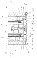
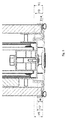
- FIGS. 2 to 4 show a cross-sectional view of the partition wall element 2 FIG. 1 according to the line AA.
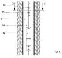
- FIG. 5 shows a cross-sectional view of the partition wall element FIG. 4 according to the line XX FIG. 1 ,
- a partition wall element 2 with a manually extendable telescoping element 23 and in the FIGS. 4 and 5 a partition wall element 2 is shown with a motor extendable telescoping element 23.
- the same diaphragm profile 6 can be used both in a manually and in a motor extendable telescoping element 23.
- the diaphragm profile 6 is in the Figures 2 and 3 in a first mounting position III and in the FIGS. 4 and 5 in a second mounting position IV.
- the diaphragm profile 6 is rotated in the first mounting position III in comparison to the diaphragm profile 6 in the second mounting position IV by 180 ° about a horizontal axis 53.
- the pressure beam 5 in a motor-extendable telescopic element 23 the same as in a manually extendable telescopic element 23.
- the partition wall element 22 with a manually extendable telescoping element 23 in a simple manner be converted into a partition wall member 22 with a motor extendable telescoping element 23.
- the pressure beam 5 has a U-shaped base profile 24 on which a first L-shaped wall portion 16 and a second L-shaped wall portion 17 of the pressure beam 5 are arranged.
- a first pressure strut holding means 9 and a second pressure strut holding means 10 are formed on the first wall section 16.
- a third pressure strut holding means 11 is formed at the second wall portion 17.
- a first stopper portion 18 and the second L-shaped wall portion 17, a second stop portion 19 connects.
- the first stop section 18 and the second stop section 19 extend at right angles to the L-shaped wall sections 16, 17, so that the short leg of an L-shaped wall section 16, 17 runs parallel to the stop section 18, 19.
- the panel profile 6 is captively arranged in or on the pressure spar 5.
- the diaphragm profile 6 has the first diaphragm holding means 7 and the second diaphragm holding means 8.
- the first and second diaphragm holding means 7, 8 are horizontally spaced.
- the first diaphragm holding means 7 is formed from a first web 12, at the distal end of a first latching lug 14 is arranged.
- the second diaphragm holding means 8 comprises a second web 13, the first web 12 and the second web 13 having approximately the same height H5 as in FIG FIG. 3 shown. At the second web 13, a second locking lug 15 is arranged.
- the webs 12,13 are formed so that they are flexurally elastic, that is, for example, when inserting the panel profile 6 in or on the pressure beam 5, by the configuration of the wall sections 16,17 causes to pivot elastically towards each other.
- the panel profile 6 can be clipped by a horizontal movement in the pressure spar 5.
- the diaphragm holding means 7, 8 form a positive connection with the pressure bar retaining means 9, 10, 11 in the telescoping direction 50.
- the diaphragm profile 6 is latched to the pressure beam 5.
- the pressure strut holding means 9, 10, 11 and the diaphragm holding means 7, 8 are formed asymmetrically to a center plane 51.
- the latching lugs 14, 15 are latched with pressure strut holding means 9, 10, 11, so that the panel profile 6 is held in the telescoping direction 50 on the pressure strut 5.
- FIG. 4 shown configuration of the distance A2 between the diaphragm profile 6 and the pressure spar 5 compared to in Fig. 2 shown configuration with the distance A1 between the diaphragm profile 6 and the pressure spar 5 has increased.
- the two diaphragm holding means 7, 8 respectively engage with different pressure bar retaining means 9, 10, 11.
- the first diaphragm holding means 7 is engaged with the first pressure bar retaining means 9
- the second diaphragm holding means 8 is engaged with the third pressure beam holding means 11 of the second wall portion 17.
- the first diaphragm holding means 7 is engaged with the third pressure beam holding means 11 of the second wall portion 17 and the second diaphragm holding means 8 is engaged with the second pressure bar retaining means 10 of the first wall section 16.
- the distance A1 of the first position V which deviates from the distance A2 of the second position VI, results.
- the second latching lug 15 is arranged at a height H2 on the second web 13, wherein the height H2 is less than the height H1 of the first latching lug 14 of the first web 12 is formed.
- the height H3 of the first pressure strut holding means 9 is greater than the height H6 of the third pressure hold means 11.
- the height H6 is again greater than the height H4 of the second pressure strut holding means 10.
- the height difference H1-H2 of the detents 14, 15 corresponds to the height difference H3- H6 of the first and third pressure strut holding means 9, 11 and the height difference H6-H4 of the third and the second pressure strut holding means 10, 11.
- the heights H1 to H6 are each related to a cover 33 of the panel profile 6.
- the diaphragm holding means 7, 8 can be clipped well both in the first and in the second mounting position III, IV, the first and second webs 12, 13 are aligned parallel to one another.
- the long legs of the first and second wall portions 16, 17 are formed parallel and spaced from the first and second web and serve as a guide for the locking lugs 14, 15th
- the panel profile 6 has the plate-like cover 33.
- the covering element 33 forms the side surface 3 of the partition wall element 2 together with the hollow chamber profiles 28.
- the covering element 33 conceals the pressure beam 5 in the vertical direction Outside facing surface of the panel profile 6 is configured consistently and advantageously has no visible from the outside fasteners, buttons or switches.
- the cover element 33 is adjoined by side parts 34, which cover a part of the cover plates 27 in a plan view of the front or rear side of the partition element.
- side parts 34 which cover a part of the cover plates 27 in a plan view of the front or rear side of the partition element.
- a cover is provided that both in a first position V of the diaphragm profile 6, the in Fig. 2 is shown, and in the second position VI, the in Fig. 4 is shown, a partial overlap of the cover plates 27 takes place, so that a transition between the cover 33 and the cover plates 27 is hidden in each case.
- the diaphragm profile is fixed substantially immovably on the pressure spar.
- a resilient element 21st arranged in the region of the first stop portion 18 and preferably in the region of the second stop portion 19 .
- This may be, for example, a rubber-like sealing tape.
- the resilient element 21 also serves for the vertical fixation of the panel profile 6 on the pressure beam 5.
- a static friction is generated by the resilient element 21, which prevents vertical movement of the panel profile 6.
- the concern of the panel profile 6 on the resilient element 21 on the pressure bar 5 also prevents a significant for the viewer movement of the panel profile 6 against the Teleskopieriques.
- the panel profile 6 in the in Fig. 4 On the other hand, the arrangement shown is movably arranged in the direction of the pressure beam 5, ie against the telescoping direction 50. If the panel profile 6 encounters an obstacle during extension, the panel profile 6 is moved counter to the telescoping direction 50 and actuates the safety switch 35 fastened to the pressure spar 5. In this way, the extension of the telescoping element 23 can be interrupted.
- the diaphragm profile 6 is movable, the diaphragm holding means 7, 8 in the second position VI against the telescoping direction 50 form-fitting manner to the pressure strut holding means 9, 10, 11 is formed. Likewise, the distal ends of the diaphragm holding means 7, 8 are spaced from the pressure beam 5 against the telescoping direction 50.
- spring elements 22 are arranged (s. FIG. 6 ), which act on the diaphragm profile 6 with a directed away from the pressure beam 5 force and in the in Fig. 3 shown second position VI against the second pressure strut holding means 10 and the third pressure strut holding means 11 press. This force can be overcome by the obstacle, so that the safety switch 35 is actuated.
- formed as leaf springs spring elements 22 are mounted on the end face 30 of the pressure beam 5.
- FIG. 4 illustrated second position VI thus corresponds to an exemption in which the diaphragm profile 6 against the telescoping 50 is actuated.
- FIG. 5 the shutter profile 6 is shown after actuation of the safety switch 35 in an operating position VII.
- the telescoping element 23 has reached an end position and thus the extended state II and abuts the wall 101.
- the diaphragm profile 6 has in the operating position VII the same distance A1 to the pressure beam 5 as in the first position V.
- seals can be used to the same extent in a manually extendable telescopic element 23 as well as a motor-extendable telescoping element 23 and the same sound insulation Offer.
- the operating position VII does not correspond to the first position V.
- the diaphragm profile 6 is not positively held in the operating position VII in Teleskopieriques 50, but the diaphragm profile 6 can by the force of the spring element 22 without lifting a form fit in the exemption FIG. 4 move back.
- the safety switch 35 can be reversibly actuated.
- the distal ends of the webs 12, 13 are provided, which previously come to rest against the pressure strut 5.
- the distal ends of the webs 12, 13 act as a stop.
- reed switch 36 (s. Fig. 6 ), which are mounted on an inner side of the cover 33.
- the reed switches 36 are intended to in the vicinity of the wall 101 to override an operation of the safety switch 35 and display so that no unwanted obstacle, but to be reached wall 101 has been reached.
- the reed switch 36 which cooperate with arranged on the wall 101 magnet, thus serve to distinguish between an unwanted obstacle and the wall 101.
- the extension of the telescoping element 23 is not immediately interrupted, but continued until the in FIG. 5 illustrated operating position VII has been achieved with the same sealing effect.
Landscapes
- Engineering & Computer Science (AREA)
- Architecture (AREA)
- Civil Engineering (AREA)
- Structural Engineering (AREA)
- Physics & Mathematics (AREA)
- Electromagnetism (AREA)
- Power-Operated Mechanisms For Wings (AREA)
- Building Environments (AREA)
- Specific Sealing Or Ventilating Devices For Doors And Windows (AREA)
Applications Claiming Priority (1)
| Application Number | Priority Date | Filing Date | Title |
|---|---|---|---|
| DE102015108663.8A DE102015108663A1 (de) | 2015-06-01 | 2015-06-01 | Trennwandelement |
Publications (2)
| Publication Number | Publication Date |
|---|---|
| EP3101192A1 true EP3101192A1 (fr) | 2016-12-07 |
| EP3101192B1 EP3101192B1 (fr) | 2021-07-14 |
Family
ID=56112838
Family Applications (1)
| Application Number | Title | Priority Date | Filing Date |
|---|---|---|---|
| EP16172304.4A Active EP3101192B1 (fr) | 2015-06-01 | 2016-05-31 | Element de paroi de separation |
Country Status (3)
| Country | Link |
|---|---|
| US (1) | US9903112B2 (fr) |
| EP (1) | EP3101192B1 (fr) |
| DE (1) | DE102015108663A1 (fr) |
Families Citing this family (3)
| Publication number | Priority date | Publication date | Assignee | Title |
|---|---|---|---|---|
| DE102015108663A1 (de) * | 2015-06-01 | 2016-12-01 | Dorma Deutschland Gmbh | Trennwandelement |
| US10494811B1 (en) * | 2018-09-07 | 2019-12-03 | Haworth, Inc. | Expandable wall start for a movable wall |
| US20230193626A1 (en) * | 2021-12-16 | 2023-06-22 | Onx, Inc. | Acoustically absorptive modular partition assembly |
Citations (1)
| Publication number | Priority date | Publication date | Assignee | Title |
|---|---|---|---|---|
| DE3425484A1 (de) * | 1984-07-11 | 1986-01-23 | aboplan Viol und Partner GmbH, 2903 Bad Zwischenahn | Versetzbare trennwand aus wandelementen und verfahren zur herstellung und demontage der wandelemente |
Family Cites Families (15)
| Publication number | Priority date | Publication date | Assignee | Title |
|---|---|---|---|---|
| US3566559A (en) * | 1968-12-23 | 1971-03-02 | Advanced Equipment Corp | Demountable wall structure |
| DE7629217U1 (de) * | 1976-09-18 | 1977-01-27 | Planacord Gmbh & Co Kg, 2900 Oldenburg | Wandelement mit ausfahrbarem ausgleichsstueck |
| US4454690A (en) * | 1976-09-28 | 1984-06-19 | Panelfold, Inc. | Portable and operable wall system |
| US4103463A (en) * | 1976-09-28 | 1978-08-01 | Panelfold Doors, Inc. | Portable wall system |
| US4277920A (en) * | 1976-09-28 | 1981-07-14 | Panelfold Doors, Inc. | Portable and operable wall systems |
| JPS5428411A (en) * | 1977-08-04 | 1979-03-03 | Kouji Unayama | Device for fixing room partition wall |
| DE3619392A1 (de) * | 1986-06-09 | 1987-12-10 | Hueppe Gmbh | Zweischaliges teleskopelement einer beweglichen trennwand |
| US5167575A (en) * | 1989-08-23 | 1992-12-01 | Macdonald Ross P | Clean room including an internal partition system |
| US5228254A (en) * | 1991-01-18 | 1993-07-20 | Plascore, Inc. | Wall system |
| DE9200754U1 (de) * | 1992-01-23 | 1992-04-23 | Hüppe Form Sonnenschutz- und Raumtrennsysteme GmbH, 2900 Oldenburg | Vorrichtung zum Aus- und Einfahren einer Dichtleiste an einem beweglichen Trennwandelement |
| US5644877A (en) * | 1995-07-25 | 1997-07-08 | Wood; Richard J. | Demountable ceiling closure |
| FR2805296B1 (fr) * | 2000-02-17 | 2002-12-27 | Jean Paul Scherrer | Profile de structure, notamment pour cloisons |
| CN105026675B (zh) * | 2013-02-27 | 2018-02-27 | 马尔斯控股公司 | 具有夹紧异型件的隔断墙系统 |
| NL2010367C2 (nl) * | 2013-02-27 | 2014-08-28 | Maars Holding Bv | Wand. |
| DE102015108663A1 (de) * | 2015-06-01 | 2016-12-01 | Dorma Deutschland Gmbh | Trennwandelement |
-
2015
- 2015-06-01 DE DE102015108663.8A patent/DE102015108663A1/de active Pending
-
2016
- 2016-05-31 EP EP16172304.4A patent/EP3101192B1/fr active Active
- 2016-05-31 US US15/169,223 patent/US9903112B2/en active Active
Patent Citations (1)
| Publication number | Priority date | Publication date | Assignee | Title |
|---|---|---|---|---|
| DE3425484A1 (de) * | 1984-07-11 | 1986-01-23 | aboplan Viol und Partner GmbH, 2903 Bad Zwischenahn | Versetzbare trennwand aus wandelementen und verfahren zur herstellung und demontage der wandelemente |
Also Published As
| Publication number | Publication date |
|---|---|
| US9903112B2 (en) | 2018-02-27 |
| DE102015108663A1 (de) | 2016-12-01 |
| US20160348363A1 (en) | 2016-12-01 |
| EP3101192B1 (fr) | 2021-07-14 |
Similar Documents
| Publication | Publication Date | Title |
|---|---|---|
| EP2333218B1 (fr) | Dispositif d'amortissement du mouvement relatif d'éléments mobiles, notamment de portes coulissantes | |
| DE7735191U1 (de) | Rolladen | |
| DE2743007A1 (de) | Sockelbalken fuer schiebetore | |
| CH707332A2 (de) | Rahmensystem für ein Insekten- und/oder Pollenschutzgitter. | |
| EP2895676A1 (fr) | Joint de porte comprenant deux plans d'étanchéité | |
| EP3101192B1 (fr) | Element de paroi de separation | |
| EP2400099A1 (fr) | Installation de battant à isolation thermique | |
| EP1836358B1 (fr) | Element de façade prefabrique | |
| AT10312U1 (de) | Tragekonstruktion zur befestigung wenigstens eines möbelantriebs | |
| EP3556986B1 (fr) | Combinaison de profilés de guidage pour une fenêtre dotée d'un caisson de volet roulant pourvu de trappe de révision côté extérieur du bâtiment | |
| DE202022106449U1 (de) | Horizontal-Jalousie mit verdeckter Spannschnur | |
| DE19630877A1 (de) | Gleitschiene | |
| EP1091081A2 (fr) | Dispositif de guidage pour un volet roulant, un store enroulable ou similaire | |
| EP0784144A1 (fr) | Joint magnétique pour porte et profilés annexes pour sa fabrication | |
| DE10000163C1 (de) | Als Vorsatzkasten ausgebildeter Rollladenkasten | |
| EP2453097A2 (fr) | Dispositif de verrouillage pour une porte sectionnelle latérale | |
| EP2439371B1 (fr) | Agencement constitué d'un agencement d'étanchéité et d'une fenêtre coulissante ou d'une porte coulissante | |
| DE3520577C2 (de) | Elektromechanische Sicherheitskontaktleiste für kraftbetätigte Tore | |
| DE102017005236A1 (de) | Fahrzeugtür mit höhenverstellbarer Fensterscheibe | |
| EP1870549A2 (fr) | Porte sectionnelle | |
| EP3708751B1 (fr) | Système de guidage pour portes coulissantes | |
| EP1231345B1 (fr) | Dispositif de verrouillage et renvoi d'angle contrôlés | |
| EP0047880A1 (fr) | Dispositif de ventilation par aérateur | |
| DE29702221U1 (de) | Schiebetür | |
| EP0672811A1 (fr) | Verrouillage de fausse manoeuvre pour une tringle de commande d'une fenêtre, d'une porte ou similaire |
Legal Events
| Date | Code | Title | Description |
|---|---|---|---|
| PUAI | Public reference made under article 153(3) epc to a published international application that has entered the european phase |
Free format text: ORIGINAL CODE: 0009012 |
|
| STAA | Information on the status of an ep patent application or granted ep patent |
Free format text: STATUS: THE APPLICATION HAS BEEN PUBLISHED |
|
| AK | Designated contracting states |
Kind code of ref document: A1 Designated state(s): AL AT BE BG CH CY CZ DE DK EE ES FI FR GB GR HR HU IE IS IT LI LT LU LV MC MK MT NL NO PL PT RO RS SE SI SK SM TR |
|
| AX | Request for extension of the european patent |
Extension state: BA ME |
|
| RAP1 | Party data changed (applicant data changed or rights of an application transferred) |
Owner name: DORMAKABA DEUTSCHLAND GMBH |
|
| STAA | Information on the status of an ep patent application or granted ep patent |
Free format text: STATUS: REQUEST FOR EXAMINATION WAS MADE |
|
| 17P | Request for examination filed |
Effective date: 20170607 |
|
| RBV | Designated contracting states (corrected) |
Designated state(s): AL AT BE BG CH CY CZ DE DK EE ES FI FR GB GR HR HU IE IS IT LI LT LU LV MC MK MT NL NO PL PT RO RS SE SI SK SM TR |
|
| STAA | Information on the status of an ep patent application or granted ep patent |
Free format text: STATUS: EXAMINATION IS IN PROGRESS |
|
| 17Q | First examination report despatched |
Effective date: 20200317 |
|
| GRAP | Despatch of communication of intention to grant a patent |
Free format text: ORIGINAL CODE: EPIDOSNIGR1 |
|
| STAA | Information on the status of an ep patent application or granted ep patent |
Free format text: STATUS: GRANT OF PATENT IS INTENDED |
|
| INTG | Intention to grant announced |
Effective date: 20210203 |
|
| GRAS | Grant fee paid |
Free format text: ORIGINAL CODE: EPIDOSNIGR3 |
|
| GRAA | (expected) grant |
Free format text: ORIGINAL CODE: 0009210 |
|
| STAA | Information on the status of an ep patent application or granted ep patent |
Free format text: STATUS: THE PATENT HAS BEEN GRANTED |
|
| AK | Designated contracting states |
Kind code of ref document: B1 Designated state(s): AL AT BE BG CH CY CZ DE DK EE ES FI FR GB GR HR HU IE IS IT LI LT LU LV MC MK MT NL NO PL PT RO RS SE SI SK SM TR |
|
| REG | Reference to a national code |
Ref country code: GB Ref legal event code: FG4D Free format text: NOT ENGLISH |
|
| REG | Reference to a national code |
Ref country code: DE Ref legal event code: R096 Ref document number: 502016013400 Country of ref document: DE |
|
| REG | Reference to a national code |
Ref country code: IE Ref legal event code: FG4D Free format text: LANGUAGE OF EP DOCUMENT: GERMAN |
|
| REG | Reference to a national code |
Ref country code: AT Ref legal event code: REF Ref document number: 1410771 Country of ref document: AT Kind code of ref document: T Effective date: 20210815 |
|
| REG | Reference to a national code |
Ref country code: LT Ref legal event code: MG9D |
|
| REG | Reference to a national code |
Ref country code: NL Ref legal event code: MP Effective date: 20210714 |
|
| PG25 | Lapsed in a contracting state [announced via postgrant information from national office to epo] |
Ref country code: SE Free format text: LAPSE BECAUSE OF FAILURE TO SUBMIT A TRANSLATION OF THE DESCRIPTION OR TO PAY THE FEE WITHIN THE PRESCRIBED TIME-LIMIT Effective date: 20210714 Ref country code: RS Free format text: LAPSE BECAUSE OF FAILURE TO SUBMIT A TRANSLATION OF THE DESCRIPTION OR TO PAY THE FEE WITHIN THE PRESCRIBED TIME-LIMIT Effective date: 20210714 Ref country code: HR Free format text: LAPSE BECAUSE OF FAILURE TO SUBMIT A TRANSLATION OF THE DESCRIPTION OR TO PAY THE FEE WITHIN THE PRESCRIBED TIME-LIMIT Effective date: 20210714 Ref country code: ES Free format text: LAPSE BECAUSE OF FAILURE TO SUBMIT A TRANSLATION OF THE DESCRIPTION OR TO PAY THE FEE WITHIN THE PRESCRIBED TIME-LIMIT Effective date: 20210714 Ref country code: FI Free format text: LAPSE BECAUSE OF FAILURE TO SUBMIT A TRANSLATION OF THE DESCRIPTION OR TO PAY THE FEE WITHIN THE PRESCRIBED TIME-LIMIT Effective date: 20210714 Ref country code: NO Free format text: LAPSE BECAUSE OF FAILURE TO SUBMIT A TRANSLATION OF THE DESCRIPTION OR TO PAY THE FEE WITHIN THE PRESCRIBED TIME-LIMIT Effective date: 20211014 Ref country code: PT Free format text: LAPSE BECAUSE OF FAILURE TO SUBMIT A TRANSLATION OF THE DESCRIPTION OR TO PAY THE FEE WITHIN THE PRESCRIBED TIME-LIMIT Effective date: 20211115 Ref country code: NL Free format text: LAPSE BECAUSE OF FAILURE TO SUBMIT A TRANSLATION OF THE DESCRIPTION OR TO PAY THE FEE WITHIN THE PRESCRIBED TIME-LIMIT Effective date: 20210714 Ref country code: BG Free format text: LAPSE BECAUSE OF FAILURE TO SUBMIT A TRANSLATION OF THE DESCRIPTION OR TO PAY THE FEE WITHIN THE PRESCRIBED TIME-LIMIT Effective date: 20211014 Ref country code: LT Free format text: LAPSE BECAUSE OF FAILURE TO SUBMIT A TRANSLATION OF THE DESCRIPTION OR TO PAY THE FEE WITHIN THE PRESCRIBED TIME-LIMIT Effective date: 20210714 |
|
| PG25 | Lapsed in a contracting state [announced via postgrant information from national office to epo] |
Ref country code: PL Free format text: LAPSE BECAUSE OF FAILURE TO SUBMIT A TRANSLATION OF THE DESCRIPTION OR TO PAY THE FEE WITHIN THE PRESCRIBED TIME-LIMIT Effective date: 20210714 Ref country code: LV Free format text: LAPSE BECAUSE OF FAILURE TO SUBMIT A TRANSLATION OF THE DESCRIPTION OR TO PAY THE FEE WITHIN THE PRESCRIBED TIME-LIMIT Effective date: 20210714 Ref country code: GR Free format text: LAPSE BECAUSE OF FAILURE TO SUBMIT A TRANSLATION OF THE DESCRIPTION OR TO PAY THE FEE WITHIN THE PRESCRIBED TIME-LIMIT Effective date: 20211015 |
|
| REG | Reference to a national code |
Ref country code: DE Ref legal event code: R097 Ref document number: 502016013400 Country of ref document: DE |
|
| PG25 | Lapsed in a contracting state [announced via postgrant information from national office to epo] |
Ref country code: DK Free format text: LAPSE BECAUSE OF FAILURE TO SUBMIT A TRANSLATION OF THE DESCRIPTION OR TO PAY THE FEE WITHIN THE PRESCRIBED TIME-LIMIT Effective date: 20210714 |
|
| PLBE | No opposition filed within time limit |
Free format text: ORIGINAL CODE: 0009261 |
|
| STAA | Information on the status of an ep patent application or granted ep patent |
Free format text: STATUS: NO OPPOSITION FILED WITHIN TIME LIMIT |
|
| PG25 | Lapsed in a contracting state [announced via postgrant information from national office to epo] |
Ref country code: SM Free format text: LAPSE BECAUSE OF FAILURE TO SUBMIT A TRANSLATION OF THE DESCRIPTION OR TO PAY THE FEE WITHIN THE PRESCRIBED TIME-LIMIT Effective date: 20210714 Ref country code: SK Free format text: LAPSE BECAUSE OF FAILURE TO SUBMIT A TRANSLATION OF THE DESCRIPTION OR TO PAY THE FEE WITHIN THE PRESCRIBED TIME-LIMIT Effective date: 20210714 Ref country code: RO Free format text: LAPSE BECAUSE OF FAILURE TO SUBMIT A TRANSLATION OF THE DESCRIPTION OR TO PAY THE FEE WITHIN THE PRESCRIBED TIME-LIMIT Effective date: 20210714 Ref country code: EE Free format text: LAPSE BECAUSE OF FAILURE TO SUBMIT A TRANSLATION OF THE DESCRIPTION OR TO PAY THE FEE WITHIN THE PRESCRIBED TIME-LIMIT Effective date: 20210714 Ref country code: CZ Free format text: LAPSE BECAUSE OF FAILURE TO SUBMIT A TRANSLATION OF THE DESCRIPTION OR TO PAY THE FEE WITHIN THE PRESCRIBED TIME-LIMIT Effective date: 20210714 Ref country code: AL Free format text: LAPSE BECAUSE OF FAILURE TO SUBMIT A TRANSLATION OF THE DESCRIPTION OR TO PAY THE FEE WITHIN THE PRESCRIBED TIME-LIMIT Effective date: 20210714 |
|
| 26N | No opposition filed |
Effective date: 20220419 |
|
| PG25 | Lapsed in a contracting state [announced via postgrant information from national office to epo] |
Ref country code: IT Free format text: LAPSE BECAUSE OF FAILURE TO SUBMIT A TRANSLATION OF THE DESCRIPTION OR TO PAY THE FEE WITHIN THE PRESCRIBED TIME-LIMIT Effective date: 20210714 |
|
| REG | Reference to a national code |
Ref country code: CH Ref legal event code: PL |
|
| PG25 | Lapsed in a contracting state [announced via postgrant information from national office to epo] |
Ref country code: MC Free format text: LAPSE BECAUSE OF FAILURE TO SUBMIT A TRANSLATION OF THE DESCRIPTION OR TO PAY THE FEE WITHIN THE PRESCRIBED TIME-LIMIT Effective date: 20210714 Ref country code: LU Free format text: LAPSE BECAUSE OF NON-PAYMENT OF DUE FEES Effective date: 20220531 Ref country code: LI Free format text: LAPSE BECAUSE OF NON-PAYMENT OF DUE FEES Effective date: 20220531 Ref country code: CH Free format text: LAPSE BECAUSE OF NON-PAYMENT OF DUE FEES Effective date: 20220531 |
|
| PG25 | Lapsed in a contracting state [announced via postgrant information from national office to epo] |
Ref country code: IE Free format text: LAPSE BECAUSE OF NON-PAYMENT OF DUE FEES Effective date: 20220531 |
|
| PG25 | Lapsed in a contracting state [announced via postgrant information from national office to epo] |
Ref country code: HU Free format text: LAPSE BECAUSE OF FAILURE TO SUBMIT A TRANSLATION OF THE DESCRIPTION OR TO PAY THE FEE WITHIN THE PRESCRIBED TIME-LIMIT; INVALID AB INITIO Effective date: 20160531 |
|
| PG25 | Lapsed in a contracting state [announced via postgrant information from national office to epo] |
Ref country code: MK Free format text: LAPSE BECAUSE OF FAILURE TO SUBMIT A TRANSLATION OF THE DESCRIPTION OR TO PAY THE FEE WITHIN THE PRESCRIBED TIME-LIMIT Effective date: 20210714 Ref country code: CY Free format text: LAPSE BECAUSE OF FAILURE TO SUBMIT A TRANSLATION OF THE DESCRIPTION OR TO PAY THE FEE WITHIN THE PRESCRIBED TIME-LIMIT Effective date: 20210714 |
|
| PG25 | Lapsed in a contracting state [announced via postgrant information from national office to epo] |
Ref country code: TR Free format text: LAPSE BECAUSE OF FAILURE TO SUBMIT A TRANSLATION OF THE DESCRIPTION OR TO PAY THE FEE WITHIN THE PRESCRIBED TIME-LIMIT Effective date: 20210714 |
|
| PG25 | Lapsed in a contracting state [announced via postgrant information from national office to epo] |
Ref country code: MT Free format text: LAPSE BECAUSE OF FAILURE TO SUBMIT A TRANSLATION OF THE DESCRIPTION OR TO PAY THE FEE WITHIN THE PRESCRIBED TIME-LIMIT Effective date: 20210714 |
|
| PGFP | Annual fee paid to national office [announced via postgrant information from national office to epo] |
Ref country code: DE Payment date: 20250521 Year of fee payment: 10 |
|
| PGFP | Annual fee paid to national office [announced via postgrant information from national office to epo] |
Ref country code: GB Payment date: 20250521 Year of fee payment: 10 |
|
| PGFP | Annual fee paid to national office [announced via postgrant information from national office to epo] |
Ref country code: BE Payment date: 20250521 Year of fee payment: 10 |
|
| PGFP | Annual fee paid to national office [announced via postgrant information from national office to epo] |
Ref country code: FR Payment date: 20250528 Year of fee payment: 10 |
|
| PGFP | Annual fee paid to national office [announced via postgrant information from national office to epo] |
Ref country code: AT Payment date: 20250522 Year of fee payment: 10 |