EP3101211A2 - Bande d'etancheite en mousse destinee a l'etancheification d'un cadre de fenetre et cadre de fenetre prepare a l'installation - Google Patents
Bande d'etancheite en mousse destinee a l'etancheification d'un cadre de fenetre et cadre de fenetre prepare a l'installation Download PDFInfo
- Publication number
- EP3101211A2 EP3101211A2 EP16170995.1A EP16170995A EP3101211A2 EP 3101211 A2 EP3101211 A2 EP 3101211A2 EP 16170995 A EP16170995 A EP 16170995A EP 3101211 A2 EP3101211 A2 EP 3101211A2
- Authority
- EP
- European Patent Office
- Prior art keywords
- sealing strip
- window frame
- foam
- strip
- window
- Prior art date
- Legal status (The legal status is an assumption and is not a legal conclusion. Google has not performed a legal analysis and makes no representation as to the accuracy of the status listed.)
- Withdrawn
Links
- 238000007789 sealing Methods 0.000 title claims abstract description 136
- 239000006260 foam Substances 0.000 title claims abstract description 49
- 238000009792 diffusion process Methods 0.000 claims abstract description 15
- IHQKEDIOMGYHEB-UHFFFAOYSA-M sodium dimethylarsinate Chemical class [Na+].C[As](C)([O-])=O IHQKEDIOMGYHEB-UHFFFAOYSA-M 0.000 claims abstract description 8
- 230000003111 delayed effect Effects 0.000 claims abstract description 6
- 238000011084 recovery Methods 0.000 claims abstract description 5
- 239000006261 foam material Substances 0.000 claims description 46
- 230000004888 barrier function Effects 0.000 claims description 35
- 230000000694 effects Effects 0.000 claims description 33
- 239000000463 material Substances 0.000 claims description 31
- 239000011248 coating agent Substances 0.000 claims description 16
- 238000000576 coating method Methods 0.000 claims description 16
- 230000006835 compression Effects 0.000 claims description 14
- 238000007906 compression Methods 0.000 claims description 14
- XLYOFNOQVPJJNP-UHFFFAOYSA-N water Chemical compound O XLYOFNOQVPJJNP-UHFFFAOYSA-N 0.000 claims description 9
- 238000009434 installation Methods 0.000 claims description 8
- 239000007787 solid Substances 0.000 claims description 5
- 230000009471 action Effects 0.000 claims description 4
- 239000004816 latex Substances 0.000 claims description 4
- 229920000126 latex Polymers 0.000 claims description 4
- 229920001971 elastomer Polymers 0.000 claims description 3
- 239000005060 rubber Substances 0.000 claims description 3
- NIXOWILDQLNWCW-UHFFFAOYSA-M Acrylate Chemical compound [O-]C(=O)C=C NIXOWILDQLNWCW-UHFFFAOYSA-M 0.000 claims description 2
- 229920001084 poly(chloroprene) Polymers 0.000 claims description 2
- 230000015572 biosynthetic process Effects 0.000 abstract 1
- 238000005516 engineering process Methods 0.000 abstract 1
- 239000004033 plastic Substances 0.000 description 5
- 229920003023 plastic Polymers 0.000 description 5
- 238000003860 storage Methods 0.000 description 4
- 239000010410 layer Substances 0.000 description 3
- 238000004519 manufacturing process Methods 0.000 description 3
- 238000004026 adhesive bonding Methods 0.000 description 2
- 239000012790 adhesive layer Substances 0.000 description 2
- 230000008901 benefit Effects 0.000 description 2
- 230000006837 decompression Effects 0.000 description 2
- 238000009472 formulation Methods 0.000 description 2
- 238000005259 measurement Methods 0.000 description 2
- 239000000203 mixture Substances 0.000 description 2
- 230000035699 permeability Effects 0.000 description 2
- 239000011148 porous material Substances 0.000 description 2
- 238000009418 renovation Methods 0.000 description 2
- 241000196324 Embryophyta Species 0.000 description 1
- 244000043261 Hevea brasiliensis Species 0.000 description 1
- 229920005830 Polyurethane Foam Polymers 0.000 description 1
- 238000009825 accumulation Methods 0.000 description 1
- 239000000853 adhesive Substances 0.000 description 1
- 230000001070 adhesive effect Effects 0.000 description 1
- 239000004566 building material Substances 0.000 description 1
- 238000005520 cutting process Methods 0.000 description 1
- 238000013016 damping Methods 0.000 description 1
- 230000003247 decreasing effect Effects 0.000 description 1
- 230000001934 delay Effects 0.000 description 1
- 230000004069 differentiation Effects 0.000 description 1
- 238000001125 extrusion Methods 0.000 description 1
- 229920001821 foam rubber Polymers 0.000 description 1
- -1 for example Polymers 0.000 description 1
- 238000005470 impregnation Methods 0.000 description 1
- 238000009413 insulation Methods 0.000 description 1
- 239000002184 metal Substances 0.000 description 1
- 238000000034 method Methods 0.000 description 1
- 229920003052 natural elastomer Polymers 0.000 description 1
- 229920001194 natural rubber Polymers 0.000 description 1
- 239000011496 polyurethane foam Substances 0.000 description 1
- 230000008569 process Effects 0.000 description 1
- 230000001681 protective effect Effects 0.000 description 1
- 230000000284 resting effect Effects 0.000 description 1
- 230000000630 rising effect Effects 0.000 description 1
- 238000005507 spraying Methods 0.000 description 1
- 229920003048 styrene butadiene rubber Polymers 0.000 description 1
- 229920003051 synthetic elastomer Polymers 0.000 description 1
- 239000005061 synthetic rubber Substances 0.000 description 1
- 230000000007 visual effect Effects 0.000 description 1
- 239000002023 wood Substances 0.000 description 1
Images


Classifications
-
- E—FIXED CONSTRUCTIONS
- E06—DOORS, WINDOWS, SHUTTERS, OR ROLLER BLINDS IN GENERAL; LADDERS
- E06B—FIXED OR MOVABLE CLOSURES FOR OPENINGS IN BUILDINGS, VEHICLES, FENCES OR LIKE ENCLOSURES IN GENERAL, e.g. DOORS, WINDOWS, BLINDS, GATES
- E06B1/00—Border constructions of openings in walls, floors, or ceilings; Frames to be rigidly mounted in such openings
- E06B1/62—Tightening or covering joints between the border of openings and the frame or between contiguous frames
- E06B2001/626—Tightening or covering joints between the border of openings and the frame or between contiguous frames comprising expanding foam strips
Definitions
- the invention initially relates to a suitable for sealing a window frame foam sealing strip, which is preferably impregnated for delayed recovery, the foam sealing strip has two opposite, respectively in the installed state of the inside or the outside of the window facing narrow sides and to the plant to the window side or Reveal appropriate broadsides.
- Foam sealing strips of the type in question for sealing a window frame are known.
- a sealing strip is shown and described, consisting of an elastically resilient foam material.
- This strip may be accommodated in a wrapping film designed as a tear film, wherein, if appropriate, after a corresponding opening of the film, the foam sealing strip delays due to an intended impregnation.
- a broad side of the foam sealing strip is adhesively bonded to a lateral surface of the window frame facing the reveal of the masonry opening. In the installed state seals the sealing strip with its other broad side against the soffit.
- the narrow sides of the sealing strip aligned transversely to these broad sides are on the one hand facing the inside and, moreover, the outside of the window.
- sealing strip of the type in question adapted to their installation more or less steam-braking. So come the window outside facing sealing strips are used, which have a lower vapor barrier effect than the inside of the window attributable sealing strips (according to DIN 4108-7).
- a sealing strip which has particular vapor diffusion advantages.
- the sealing strip according to the invention is set so that a predefined inside and outside of the same exists. Due to the different setting of the vapor barrier effect of the one and the other narrow side, a clear diffusion direction is indicated, namely from the side of higher vapor barrier effect to the side on the other hand, lower vapor barrier effect.
- Such a set sealing strip can take over the function of a room inside as well as a space outer side arranged strip with a corresponding arrangement.
- the defined diffusion direction makes this possible.
- these can be clearly marked, for example by color recognition.
- the sealing strip is formed with such a width that the same sealing strip provides both the seal to the room inside and to the outside of the room.
- the sealing strip therefore combines the known from the prior art single-sealing strips for sealing the room inside and for sealing the room outside. Accordingly, this gives a handling technical advantage, because now only one sealing strip assigned to a window frame leg is to be arranged.
- the sealing strip preferably extends over approximately the entire thickness of the window frame, wherein further the sealing strip is held in an arrangement on the window frame, for example. By gluing initially in a restored, compressed position, which compression is, for example, released by tearing a wrapping film.
- the sealing strip may in this case be impregnated in such a way that results in a delayed reset.
- the created integral sealing strip can, for example, be marked in color along its correspondingly set narrow sides, for example.
- the invention further relates to a window frame used in a window reveal of a house or prepared for installation, wherein the window frame is sealed relative to a soffit or a jamb element by means of a sealing strip, that to the interior of the window frame, a higher vapor barrier effect is formed as to the room outside.
- Window frames of the type in question are known. With regard to the sealing strip to be inserted between the window frame and the reveal, reference is made to the prior art mentioned in the introduction.
- a window frame of the type in question is created, which is characterized in particular by a simplified assembly. It requires according to the proposal of the invention only the arrangement of a sealing strip, assigned to the soffit facing frame narrow side.
- the sealing strip preferably extends over approximately the entire thickness of the window frame.
- the sealing strip is preferably held by gluing to the window frame further initially in a restored, compressed position, which compression is released in a possible embodiment by tearing open a wrapping film.
- the sealing strip fulfills the requirement according to DIN 4108-7, according to which a higher vapor barrier effect must be given to the interior of the room than to the outside of the room. This is achieved in the present case by only one sealing strip, which is further adjusted in particular room interior side according to obtain the higher vapor barrier effect.
- the higher vapor barrier effect is achieved by a one-sided, strip narrow-side coating.
- This coated side is in the installed state, ie facing the arrangement of the window frame and further when inserted in the window reveal window frame of the room inside.
- the otherwise across the entire width of the sealing strip - viewed from a narrow side to the opposite narrow side - basically a constant vapor barrier effect having foam material is partially covered by the proposed coating, namely assigned only a narrow edge area to thereby achieve a clearly defined portion of increased vapor barrier effect.
- the coating material is adjusted elastically in accordance with the ability of the foam material to return, wherein over the entire possible restoring dimension of the sealing strip, the higher vapor barrier effect compared to the rest of the foam material, in particular with respect to the outside edge facing narrow edge is secured.
- latex may be used as the coating material.
- This may be a synthetically produced latex material, as they are known, for example from the carpet backing forth.
- acrylate, neoprene or rubber such as, for example, styrene-butadiene rubber (SBK), natural rubber, synthetic rubber or chlorinated rubber.
- SBK styrene-butadiene rubber
- This coating material is applied in the course of the production of the sealing strip after cutting the foam material on a narrow side surface, so on, for example, after compression of the foam material in the storage position by means of roller or brush application or by spraying.
- the higher vapor barrier effect can also be achieved by a one-sided higher compression of the foam in the installed state, so on, for example, by a higher material density over the same height of the narrow side.
- This higher material density or the higher compression is in the installed state, ie in the rest state of the sealing strip after a complete recovery and investment against the facing window reveal before.
- the foam strip in the fully decompressed state along the narrower side later having the higher vapor braking effect have a much greater thickness than in the other narrow edge side facing, later less vapor-damping area. Due to this accumulation of material along one narrow side, an increased material density and thus the desired higher vapor barrier effect are achieved in the compressed installation state.
- the higher material density may be achieved by having a lower height than the foam having additional foam material.
- a combination of the actual sealing strip foam material and the additional foam material is provided over the height of the strip, which combination preferably does not generally exceed the height of the foam strip.
- the additional foam material may be embedded in strips in the sealing strip foam.
- This additional foam material may further consist of the same material as the other foam strip. The embedding of this additional strip is carried out by compressing the associated strip portion of the sealing strip foam material, according to which there is an increased material density in the associated narrow edge region.
- the additional foam material may also be a closed-cell foam, compared to the generally open-pore configuration of the sealing strip foam material.
- the higher material density can also be achieved in that part of the height is formed by means of a solid strip, for example plastic strip, with the same foam height of the expanded foam material.
- This strip can be an integral part of the sealing strip, is fed accordingly in the course of the production of the sealing strip of the corresponding narrow edge side, for compression of the relevant foam area, which causes the desired increased vapor barrier effect.
- This strip can also be alternatively positioned between the window frame and sealing strip positioned facing the interior of the room so as to partially, facing the interior, to reduce the gap between the window frame and facing window reveal, which in turn leads to a higher compression of the sealing strip foam material in the region of the interior space.
- the solid bar may extend over the entire, suitable for engagement with the window side or soffit broadside and have to achieve a different material density of the foam across the width zones of different bar strengths.
- Such profiled in cross-section bar carries a foam which viewed in the expanded position over the broad side has the same foam height.
- the foam when placed between a soffit and a window frame, the foam is less compressed in the area of a trough-forming portion of the solidly formed bar than in an increase zone of the bar in comparison thereto, in which area a relatively high compression of the foam material is achieved ,
- a profiled in cross-section bar can be supplied in the course of the production of the sealing strip of the corresponding broad side of the foam, so on, for example, be sprayed.
- the strip thus formed is present as an integral part of the sealing strip.
- the area of the foam defining the interior vapor barrier effect has a water vapor diffusion resistance value, also Sd value, which is 2 to 150 times the water vapor diffusion value of the vapor barrier effect on the outside corresponds to the defining area.
- a room interior value is selected which is 2 to 50 times, for example 7, 10, 13 or 25 times, further eg 27, 32, 35 or 43 times corresponds to the space outside value.
- the different water vapor diffusion resistance values to the areas facing the room outside or inside the room are by measurements eg. From the core of the foam outwards into the assigned areas or by measurements of a separate and thus only either a room outside assignable area or a space inside assignable area having foam Determine sealing strip.
- a water vapor diffusion resistance value is between 0.1 and 10 m provided, more preferably a value between 1 and 5 m.
- the proposed integral foam sealing strip is preferably positioned between a window frame and the associated window reveal.
- a sealing strip can also be arranged between a window frame and an associated reveal element for a window opening, which reveal element is used in particular for window renovations.
- a soffit element is, for example, from the DE 102004006403 A1 known.
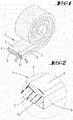
- a foam sealing strip 1 in a first embodiment. This is preferably for use in roll form.
- the selected foam material is more preferably a flexible polyurethane foam. This is possibly impregnated, so on, for example, by means of Acrylatzu instrumentsn so as to offer the sealing strip with a delayed provision. Accordingly, the sealing strip 1 in storage position corresponding to the above-mentioned EP 1 131 525 B1 be kept in a tearable wrapping film in the compressed state.
- Alternative embodiments provide a sealing strip 1 without tear-off.
- the foam sealing strip 1 has a cross section as shown in FIG Fig. 3 on, with two broadsides 2, 3 and two i. W. at right angles to this extending narrow sides 4,5.
- the broad sides 2 and 3 have a length b, which corresponds to a multiple of the measured perpendicular to this length a of the narrow sides 4 and 5 respectively. This is the case both in an optionally present compressed, further possibly enveloped state of the sealing strip 1 and after a return (decompression) of the sealing strip in the installed state.
- the foam sealing strip 1 is used to seal a joint between a window frame 6 and the facing window reveal 7.
- the sealing strip 1 is provided on a broad side 2 with an adhesive layer 8, which is covered in the storage state of a protective film 9, for example. Siliconized film.
- the sealing strip 1 is fixed on the cheek of the fixed window frame 6 which faces the window reveal 7 and extends approximately parallel thereto.
- the sealing strip 1 seals, possibly after triggering by tearing open a wrapping film and its subsequent delayed return with the window frame 6 facing away from broadside 3 against the window reveal 7.
- the sealing strip 1 is to comply with the requirement known from the RAL that with respect to the vapor barrier effect to the room inside out a higher value must be present as the room outside, adjusted accordingly.
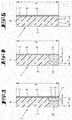
- This zone 10 increased material density is created by embedding an additional foam material 11, which is a closed-cell foam in the illustrated embodiment.
- This additional foam material 11 is in strip form, with one of the narrow side. 5 of the sealing strip 1 facing narrow edge 12 which extends in the plane of the space inside narrow side 5 of the sealing strip 1.
- the additional foam material 11 is the corner between inner side narrow side 5 and the window frame 6 facing broad side 2 of the sealing strip 1, wherein the perpendicular to the narrow edge 12 extending widthwise cheek 13 of the additional foam material 11 extends in the plane of the sealing strip broadside 2 ,
- the measured in the direction of the narrow side width a height c of the additional foam material 11 corresponds to only a portion of the narrow side length a, so for example. In the illustrated embodiment, about a third to a quarter of the narrow side length a.
- the extension length measured perpendicular to the height h parallel to the sealing strip broad side 2 corresponds approximately to 3 to 5 times the material height h.
- the additional foam material 11 is embedded in the foam material of the sealing strip 1 and non-detachably connected thereto. According to the cross-sectional configuration of the additional foam material 11, there may be an open-edge pocket in the sealing strip foam material for receiving the additional foam material 11.
- the required increased vapor barrier effect with respect to the sealing strip narrow side 4 assigned to the outside A is in this case achieved by influencing the cross-section through the insert of the additional foam material 11 in the form of a closed-pore material.
- the additional foam material 11 as shown can also be integrated with compression of the soft foam material lying in overlap therewith. Due to the higher material density achieved in this case compared to the outer narrow side 4, the requirement according to DIN 4108-7 is reached, in which case the additional foam material 11 can also consist of the same open-cell flexible foam material as the remaining sealing strip 1.
- the higher material density in the region of the inner side I associated narrow side 5 can be achieved by a solid trained bar 14, which acts according to the above-described additional foam material 11 on the narrow side 5 associated zone 10.
- This bar 14 may frame side corresponding to the inside I facing arranged.
- the plastic strip 14 is set to be vapor-impermeable. In connection with the zone 10 of the sealing strip 1 compressed by the action of the strip 14, this leads to the vapor braking effect which is increased in relation to the opposite narrow side 4.
- the increased vapor barrier effect can be achieved on the inner side 1 to be assigned sealing strip narrow side 5 by a coating of this narrow side 5.
- This coating 15 (see. Fig. 5 , as well as installation example according to Fig. 6 ) may be based on latex.
- this coating 15 is a kind of vapor barrier on the narrow side 5 is set, wherein the elasticity of the sealing strip material is not affected by the selected coating material, in particular for resetting the same for sealing engagement against the window reveal 7. Accordingly, a coating material is chosen which allows the decompression of the foam material.
- the coating 15 can also be formed, for example, by an elastic sealing strip applied on the narrow side 5 facing the space inside, so on, for example, by a closed-cell plastic strip.
- the sealing strip 1 forms an integral sealing element for a fixed window frame 6 according to the selected cross-sectional dimensions and the different vapor permeability values to the outside A and to the inside I.
- the sealing strip 1 can according to the representations in the FIGS. 6 and 7 adhesively bonded to the window frame 6 directly with the window reveal 7. Alternatively, the arrangement may also be as shown in FIG Fig. 8 be provided, wherein the sealing strip 1 seals against a made of a hard plastic material soffit element 16, which, for example, in the window renovation is used.
- a further embodiment of the sealing strip 1 is shown. Similar to the embodiment shown in FIG Fig. 4 or 8, a combination of strip 14 and foam is also provided here.
- This strip 14 extends over the entire, here the window frame 6 facing broad side 2, which broadside 2 can serve at the same time via an adhesive zone for fixing the bar 14. Shown is an embodiment in which on the broad side 2 a plug-in holder with the window frame 6 is reached. According to this embodiment, the narrow sides 4 'and 5' of the strip 14, which extend perpendicular to the broad side 2, are respectively directly facing the outer side A and the inner side I, respectively.
- the strip 14 is in cross section as shown in FIG Fig. 9 profiled in such a way that, viewed over the extent dimension of the broad side 2, different profile heights result.
- facing the narrow side 5 ', ie further facing the interior of the room I I provided a zone 20 greater strip thickness and higher levels relative to the broad side 3 for the foam.
- the bar 14 extends transversely to the joint alignment considered about two thirds of the joint width f.
- a zone 21 Adjacent to the zone 20, a zone 21 is provided. This has a relation to the zone 20 substantially reduced level. According to the illustrated embodiment, this reverses the ratio of pad level to joint width compared to the area of the zone 20, so that the strip thickness here corresponds to less than one third of the joint width f, up to a ratio at which the thickness of the foam material, the joint width f reached.
- the strip 14 is in the region of its broad side 2 in an associated recess of the window frame.
- the zone 20 terminates in a flat, parallel to the broad side 2 aligned surface
- the adjoining region of the zone 21 is defined in cross-section by a concave profile of the strip edge, further as shown, starting from the zone 20, the zone 21 initially continuously decreasing, but finally in the direction of the outside of the room A facing narrow side 4 'is slightly rising again, although the end of the zone 21, the narrow side 4' facing the measured transverse to the broad side edition level for the foam material less than half Fugenures corresponds.
- the zone 21 occupies about two thirds to three quarters of the total width of the bar 14 a.
- the foam material On the side facing away from the broad side 2 profiled surface of the bar 14 - on the different circulation levels - the foam material is not detachably connected to the bar 14.
- the foam strip has a uniform foam height at free expansion. Accordingly, the arranged on the bar 14 foam strip is due to the profiling described in the installed state as shown in FIG Fig. 9 compressed on one side at the end to achieve a higher material density.
- This zone 10 of increased density is associated with the zone 20 of the strip 14, in which zone 20, the strip 14 has a relation to the zone 21 increased bar thickness.
- the narrow sides 4 and 5 of the foam material are partially flanked in the illustrated embodiment, but at least over the support level of the reinforced zone 20 projecting from integrally formed with the bar 14 side walls 22.
- the latter are dimensioned so that the resulting narrow sides 4 'and 5' of the strip 14 in the width direction have a smaller dimension than the width f of the joint to be sealed.
- the side walls 22 provide lateral support of the foam material.
- the foam material is preferably an impregnated sealing tape.
- the strip 14 is, for example, produced in the plastic extrusion process, but may alternatively be formed by drawing a metal strand or as a milled wood profile.
- the degree of compression in the region of the narrow side 4 facing the outer side A corresponds to approximately 50% of the degree of compression of the narrow side 5 associated with the inner side I.
- a greater expansion is achieved by the concave profile curvature relative to the outer side A. This corresponds in the illustrated embodiment, in turn, about 50% of the degree of compression of the foam in the outer side A facing area.
- the sealing strip 1 in which the sealing strip 1 is present for installation or arrangement on the window frame in the compressed, optionally foil-packed state, the sealing strip 1 can also, in particular if the increased vapor barrier effect on the inner narrow side 5 is made by a coating 15, only in the course of attachment of the sealing strip 1 to the window frame 6 are compressed.
- the proposed sealing strip 1 provides both the combination required for the outside A towards sealing against driving rain, which is usually achieved by the compressed state of rest in the installed state of the sealing strip 1, as well as viewed in the direction of width extension medium density level as thermal insulation, and the required vapor barrier effect or against the Outside increased vapor barrier effect to the room inside out.
Landscapes
- Engineering & Computer Science (AREA)
- Civil Engineering (AREA)
- Structural Engineering (AREA)
- Specific Sealing Or Ventilating Devices For Doors And Windows (AREA)
- Building Environments (AREA)
Applications Claiming Priority (4)
| Application Number | Priority Date | Filing Date | Title |
|---|---|---|---|
| DE102006002624 | 2006-01-19 | ||
| DE102006031307 | 2006-07-06 | ||
| DE102006043050A DE102006043050A1 (de) | 2006-01-19 | 2006-09-14 | Zur Abdichtung eines Fensterrahmens geeigneter Schaumstoff-Dichtstreifen sowie zum Einbau vorbereiteter Fensterrahmen |
| EP06126454.5A EP1811111B2 (fr) | 2006-01-19 | 2006-12-19 | Baie de fenêtre avec cadre dormant et joint d'étanchéité |
Related Parent Applications (2)
| Application Number | Title | Priority Date | Filing Date |
|---|---|---|---|
| EP06126454.5A Division EP1811111B2 (fr) | 2006-01-19 | 2006-12-19 | Baie de fenêtre avec cadre dormant et joint d'étanchéité |
| EP06126454.5A Division-Into EP1811111B2 (fr) | 2006-01-19 | 2006-12-19 | Baie de fenêtre avec cadre dormant et joint d'étanchéité |
Publications (2)
| Publication Number | Publication Date |
|---|---|
| EP3101211A2 true EP3101211A2 (fr) | 2016-12-07 |
| EP3101211A3 EP3101211A3 (fr) | 2017-03-01 |
Family
ID=37908043
Family Applications (4)
| Application Number | Title | Priority Date | Filing Date |
|---|---|---|---|
| EP12178497.9A Active EP2520749B1 (fr) | 2006-01-19 | 2006-12-19 | Bande d'étanchéité en mousse destinée à l'étanchéification d'un cadre de fenêtre et cadre de fenêtre préparé à l'installation |
| EP06126454.5A Active EP1811111B2 (fr) | 2006-01-19 | 2006-12-19 | Baie de fenêtre avec cadre dormant et joint d'étanchéité |
| EP12178691.7A Withdrawn EP2520750A3 (fr) | 2006-01-19 | 2006-12-19 | Bande d'étanchéité en mousse destinée à l'étanchéification d'un cadre de fenêtre et cadre de fenêtre préparé à l'installation |
| EP16170995.1A Withdrawn EP3101211A3 (fr) | 2006-01-19 | 2006-12-19 | Bande d'etancheite en mousse destinee a l'etancheification d'un cadre de fenetre et cadre de fenetre prepare a l'installation |
Family Applications Before (3)
| Application Number | Title | Priority Date | Filing Date |
|---|---|---|---|
| EP12178497.9A Active EP2520749B1 (fr) | 2006-01-19 | 2006-12-19 | Bande d'étanchéité en mousse destinée à l'étanchéification d'un cadre de fenêtre et cadre de fenêtre préparé à l'installation |
| EP06126454.5A Active EP1811111B2 (fr) | 2006-01-19 | 2006-12-19 | Baie de fenêtre avec cadre dormant et joint d'étanchéité |
| EP12178691.7A Withdrawn EP2520750A3 (fr) | 2006-01-19 | 2006-12-19 | Bande d'étanchéité en mousse destinée à l'étanchéification d'un cadre de fenêtre et cadre de fenêtre préparé à l'installation |
Country Status (8)
| Country | Link |
|---|---|
| EP (4) | EP2520749B1 (fr) |
| DE (2) | DE102006043050A1 (fr) |
| DK (2) | DK1811111T4 (fr) |
| ES (1) | ES2585227T3 (fr) |
| HU (1) | HUE029338T2 (fr) |
| PL (2) | PL1811111T5 (fr) |
| PT (1) | PT1811111T (fr) |
| SI (1) | SI1811111T1 (fr) |
Families Citing this family (32)
| Publication number | Priority date | Publication date | Assignee | Title |
|---|---|---|---|---|
| DE102008049210A1 (de) | 2007-11-27 | 2009-05-28 | Tremco Illbruck Produktion Gmbh | Schaumstoff-Dichtstreifen |
| DE102008020955C5 (de) * | 2008-04-25 | 2018-05-03 | Tremco Illbruck Produktion Gmbh | Fugendichtband |
| DE102008025019A1 (de) * | 2008-04-28 | 2009-10-29 | Tremco Illbruck Produktion Gmbh | Fensterrahmen, Verfahren zum Einbau eines Fensters, Schaumstoff-Dichtband, Verfahren zum Abdichten eines Fensterrahmens und Behältnis mit Schaumstoff-Dichtband |
| DE102009013107A1 (de) * | 2008-05-13 | 2009-11-19 | Tremco Illbruck Produktion Gmbh | Schaumstoff-Dichtstreifen |
| EP2358964A1 (fr) | 2008-11-17 | 2011-08-24 | Tremco illbruck Produktion GmbH | Procédé pour l'étanchéité d'un joint de maçonnerie et élément d'étanchéité |
| DE102008063371A1 (de) * | 2008-12-30 | 2009-12-31 | Henkel Ag & Co. Kgaa | Vorkomprimiertes verzögert zurückstellendes Schaumstoffdichtband zur Abdichtung von Fugen zwischen Fensterrahmen und Baukörper |
| DE102009026864B4 (de) * | 2009-06-09 | 2017-01-12 | Odenwald-Chemie Gmbh | Dichtelement mit thermoexpandierbarer Substanz und wärmegedämmtes System mit solchem Dichtelement |
| DE102009048110A1 (de) | 2009-10-02 | 2011-04-07 | Tremco Illbruck Produktion Gmbh | Schaumstoff-Dichtband |
| EP2336442B1 (fr) | 2009-12-11 | 2013-07-31 | ISO-Chemie GmbH | Bande d'étanchéité et procédé d'équipement d'un composant pourvu d'une bande d'étanchéité |
| DE202010000317U1 (de) | 2010-02-09 | 2011-08-17 | Tremco Illbruck Produktion Gmbh | Schaumstoff-Dichtstreifen und Fensterrahmen mit Schaumstoff-Dichtstreifen |
| DE202010005431U1 (de) | 2010-05-11 | 2011-10-12 | Tremco Illbruck Produktion Gmbh | In eine Bauwerksfuge einbringbares Heizelement und Dichtelement |
| DE202010008331U1 (de) | 2010-08-23 | 2011-11-29 | Tremco Illbruck Produktion Gmbh | Schaumstoff-Dichtstreifen |
| DE102010055788A1 (de) | 2010-12-23 | 2012-06-28 | Hanno-Werk Gmbh & Co. Kg | Fugendichtungsband |
| DE202011005416U1 (de) | 2011-04-19 | 2012-07-20 | Tremco Illbruck Produktion Gmbh | Dichtstreifen |
| DE202011005415U1 (de) | 2011-04-19 | 2012-07-20 | Tremco Illbruck Produktion Gmbh | Dichtstreifen |
| DE102011050497A1 (de) | 2011-05-19 | 2012-11-22 | Chemiefac Gmbh | Verfahren zur Herstellung eines Dichtstreifens |
| DE202011104063U1 (de) | 2011-08-04 | 2014-12-09 | Tremco Illbruck Produktion Gmbh | Fugendichtband sowie Bauwerk mit derartigem Dichtband |
| DE202011107000U1 (de) | 2011-10-21 | 2013-01-29 | Tremco Illbruck Produktion Gmbh | Dichtband |
| DE202012101990U1 (de) | 2012-05-23 | 2013-08-27 | Tremco Illbruck Produktion Gmbh | Dichtband |
| DE202012005049U1 (de) | 2012-05-23 | 2013-08-26 | Tremco Illbruck Produktion Gmbh | Dichtband |
| DE202012103636U1 (de) | 2012-09-21 | 2014-01-02 | Tremco Illbruck Produktion Gmbh | Dichtband und Wandaufbau mit solchem |
| DE202012104454U1 (de) | 2012-11-19 | 2014-02-25 | Tremco Illbruck Produktion Gmbh | Zwangsbelüftetes Gebäude mit Wandaufbau umfassend Dichtungsband |
| PL2899353T3 (pl) * | 2014-01-24 | 2017-05-31 | Iso-Chemie Gmbh | Element oporowo-izolacyjny w postaci taśmy do podpierania i izolowania ramy okiennej |
| EP2899356B1 (fr) * | 2014-01-24 | 2016-05-04 | ISO-Chemie GmbH | Élément d'étanchéité permettant d'isoler de façon étanche des joints dans la zone de fenêtres |
| DE102014111149A1 (de) * | 2014-08-05 | 2016-02-11 | Odenwald-Chemie Gmbh | Dichtungselement und Verfahren zu seiner Herstellung |
| EP3124712B1 (fr) | 2015-07-30 | 2023-06-28 | Hanno Werk GmbH & Co. KG | Bande de garniture de joint compressible et son procede de fabrication |
| EP3346068B2 (fr) | 2017-01-06 | 2024-08-21 | Hanno-Werk GmbH & Co. KG | Mousse et bande de joint d'étanchéité, comprenant une telle mousse |
| EP3489293B1 (fr) | 2017-11-24 | 2023-07-12 | Hanno Werk GmbH & Co. KG | Bande de joint d'étanchéité, comprenant une mousse contenant au moins un material a changement de phase |
| EP3470610A1 (fr) | 2018-03-16 | 2019-04-17 | Hanno-Werk GmbH & Co. KG | Bande d'étanchéité pour joints et procédé de production |
| DE102018118854A1 (de) | 2018-08-02 | 2020-02-06 | tremco illbruck GmbH | Herstellungsverfahren für Dichtband und Dichtband |
| EP3878619B1 (fr) | 2020-03-13 | 2025-07-02 | Hanno-Werk GmbH & Co. KG | Procédé d'imprégnation partielle d'une mousse |
| EP4575114A1 (fr) | 2023-12-22 | 2025-06-25 | Hanno-Werk GmbH & Co. KG | Bande d'étanchéité de joints |
Citations (2)
| Publication number | Priority date | Publication date | Assignee | Title |
|---|---|---|---|---|
| EP1131525B1 (fr) | 1999-09-17 | 2004-03-03 | illbruck Building Systems GmbH | Bande d'etancheite pour rendre etanche une jointure |
| DE102004006403A1 (de) | 2004-02-10 | 2005-08-25 | Illbruck Building Systems Gmbh | Laibungselement für eine Fensteröffnung |
Family Cites Families (24)
| Publication number | Priority date | Publication date | Assignee | Title |
|---|---|---|---|---|
| DE1912156C3 (de) † | 1969-03-11 | 1979-10-18 | Heinz 4000 Duesseldorf Suellhoefer | Fugendichtungsmaterial auf Polyurethanweichschaumbasis |
| DE2836143A1 (de) † | 1978-08-18 | 1980-02-28 | Salamander Chem | Dichtungsmaterial und verfahren zu dessen herstellung |
| DE3133271A1 (de) † | 1981-08-22 | 1983-03-03 | Irbit Holding AG, 1701 Fribourg | Zu einer rolle aufgewickelter schaumstoff-streifen, vorzugsweise zu abdichtungszwecken |
| EP0317833A1 (fr) * | 1987-11-23 | 1989-05-31 | Irbit Research + Consulting AG | Elément d'étanchéité |
| DE4040015C1 (fr) † | 1990-12-14 | 1992-06-04 | Deutsche Schlauchbootfabrik Hans Scheibert Gmbh & Co Kg, 3456 Eschershausen, De | |
| DE4040156C2 (de) | 1990-12-15 | 2001-11-08 | Irbit Res & Consulting Ag Frei | Formkörper |
| DE9105612U1 (de) | 1991-05-07 | 1991-07-04 | Mader, Kurt, 6942 Mörlenbach | Rahmen für ein Fenster, eine Tür oder für die Auskleidung eines sonstigen Wandungsausbruches in einem Gebäude, sowie Dichtungsprofil für einen solchen Rahmen |
| DE4307528A1 (de) * | 1993-03-10 | 1994-09-15 | Illbruck Gmbh | Fugendichtungsband |
| DE9312987U1 (de) * | 1993-08-31 | 1995-01-05 | Illbruck Gmbh, 51381 Leverkusen | Schaumstoffelement |
| DE9410234U1 (de) * | 1994-06-24 | 1994-09-01 | Eibel, Herbert, 56077 Koblenz | Profilsatz zur Rundumverleistung von Fenster- und Türelementen am Baukörper |
| DE19624026C2 (de) * | 1996-06-17 | 2000-06-08 | Tack Klebeband Gmbh D | Vorrichtung zum Einbringen einer Dehnungsfuge zwischen zwei Bauelementen |
| DE20009674U1 (de) * | 1999-06-09 | 2000-09-14 | Hanno-Werk GmbH & Co. KG, 30880 Laatzen | Mehrlagiges Dichtungsband zum Abdichten von Fugen |
| EP1228281B1 (fr) * | 1999-11-09 | 2008-06-18 | Henkel AG & Co. KGaA | Bande de film, cadre de fenetre pourvu d'une telle bande et utilisation de cette bande |
| DE10055865B4 (de) * | 2000-11-10 | 2004-01-29 | Alfred Blos | Abdichtmittel zur Erstellung eines rahmeninnenseitig diffusionsdichten und rahmenaußenseitig diffusionsoffenen und schlagregendichten wärmegedämmten Wandanschlusses für in Außenwände eingebaute Fenster- oder Türrahmen |
| DE20019100U1 (de) * | 2000-11-10 | 2002-03-21 | Krecké, Edmond Dominique, Beaufort | Fenster und Tür sowie Schließeinrichtung mit erheblich verbesserter Wärmeisolation |
| DE10105096A1 (de) * | 2001-02-05 | 2002-08-22 | Koester Bauchemie Gmbh | Fugenabdichtungsband |
| EP1426540B1 (fr) * | 2002-12-05 | 2016-04-06 | Konrad Dipl.-Ing. Lehrhuber | Dispositif d'étanchéité pour joints entre un élément de construction et une paroi ainsi qu'un profilé d'étanchéité correspondant |
| DE102004016027A1 (de) | 2004-03-30 | 2005-10-20 | Profine Gmbh | Dichtungsprofil und Verfahren zum Montieren und Abdichten eines Rahmenbauteils |
| DE102004016036A1 (de) * | 2004-03-30 | 2005-10-13 | Profine Gmbh | Dichtungsprofil und Verfahren zum Montieren und Abdichten eines Rahmenbauteils |
| DE102009013107A1 (de) † | 2008-05-13 | 2009-11-19 | Tremco Illbruck Produktion Gmbh | Schaumstoff-Dichtstreifen |
| DE202010008322U1 (de) † | 2010-08-20 | 2011-11-21 | Tremco Illbruck Produktion Gmbh | Schaumstoff-Dichtband in einer Bauwerksfuge und Schaumstoff-Dichtband |
| DE202010008331U1 (de) † | 2010-08-23 | 2011-11-29 | Tremco Illbruck Produktion Gmbh | Schaumstoff-Dichtstreifen |
| DE202011005416U1 (de) † | 2011-04-19 | 2012-07-20 | Tremco Illbruck Produktion Gmbh | Dichtstreifen |
| DE202013104268U1 (de) † | 2013-09-18 | 2015-01-09 | Tremco Illbruck Produktion Gmbh | Dichtband |
-
2006
- 2006-09-14 DE DE102006043050A patent/DE102006043050A1/de not_active Ceased
- 2006-12-19 DK DK06126454.5T patent/DK1811111T4/da active
- 2006-12-19 HU HUE06126454A patent/HUE029338T2/en unknown
- 2006-12-19 ES ES06126454.5T patent/ES2585227T3/es active Active
- 2006-12-19 EP EP12178497.9A patent/EP2520749B1/fr active Active
- 2006-12-19 EP EP06126454.5A patent/EP1811111B2/fr active Active
- 2006-12-19 DE DE202006020799U patent/DE202006020799U1/de not_active Expired - Lifetime
- 2006-12-19 PL PL06126454T patent/PL1811111T5/pl unknown
- 2006-12-19 PL PL12178497T patent/PL2520749T3/pl unknown
- 2006-12-19 DK DK12178497.9T patent/DK2520749T3/da active
- 2006-12-19 EP EP12178691.7A patent/EP2520750A3/fr not_active Withdrawn
- 2006-12-19 EP EP16170995.1A patent/EP3101211A3/fr not_active Withdrawn
- 2006-12-19 PT PT6126454T patent/PT1811111T/pt unknown
- 2006-12-19 SI SI200632088A patent/SI1811111T1/sl unknown
Patent Citations (2)
| Publication number | Priority date | Publication date | Assignee | Title |
|---|---|---|---|---|
| EP1131525B1 (fr) | 1999-09-17 | 2004-03-03 | illbruck Building Systems GmbH | Bande d'etancheite pour rendre etanche une jointure |
| DE102004006403A1 (de) | 2004-02-10 | 2005-08-25 | Illbruck Building Systems Gmbh | Laibungselement für eine Fensteröffnung |
Also Published As
| Publication number | Publication date |
|---|---|
| DK2520749T3 (da) | 2019-05-27 |
| EP2520749B1 (fr) | 2019-02-20 |
| EP3101211A3 (fr) | 2017-03-01 |
| ES2585227T3 (es) | 2016-10-04 |
| DE102006043050A1 (de) | 2007-07-26 |
| PL1811111T5 (pl) | 2022-01-31 |
| DK1811111T4 (da) | 2019-07-22 |
| EP1811111B2 (fr) | 2019-04-17 |
| SI1811111T1 (sl) | 2016-09-30 |
| DE202006020799U1 (de) | 2010-03-11 |
| EP2520750A3 (fr) | 2014-06-18 |
| PL2520749T3 (pl) | 2019-08-30 |
| EP1811111A3 (fr) | 2010-05-12 |
| EP1811111B1 (fr) | 2016-05-25 |
| HUE029338T2 (en) | 2017-02-28 |
| PT1811111T (pt) | 2016-08-30 |
| PL1811111T3 (pl) | 2017-01-31 |
| EP2520750A2 (fr) | 2012-11-07 |
| EP1811111A2 (fr) | 2007-07-25 |
| DK1811111T3 (en) | 2016-09-05 |
| EP2520749A3 (fr) | 2014-06-11 |
| EP2520749A2 (fr) | 2012-11-07 |
Similar Documents
| Publication | Publication Date | Title |
|---|---|---|
| EP1811111B1 (fr) | Baie de fenêtre avec cadre dormant et joint d'étanchéité | |
| EP2743416B1 (fr) | Ruban d'étanchéité doté de bandes fonctionnelles | |
| DE10066070A1 (de) | Profilleiste zum Abdichten einer Bewegungsfuge zwischen einem Bauteil und einer Putzschicht | |
| EP1942237B1 (fr) | Bande pour crépi en deux pièces | |
| EP2423396B1 (fr) | Bande étanche alvéolaire | |
| DE20008712U1 (de) | Profilleiste zum Abdichten einer Bewegungsfuge zwischen einem Bauteil und einer Putzschicht | |
| EP1627982B1 (fr) | Profilé de jonction | |
| EP2492429B1 (fr) | Bande de crépissage ainsi qu'angles de construction dotés d'une bande de crépissage | |
| DE202011005416U1 (de) | Dichtstreifen | |
| DE202014104934U1 (de) | Dichtband | |
| DE19750161A1 (de) | Strangförmige Universaldichtung für Fenster, Türen oder dergleichen | |
| DE102015202882B4 (de) | Dichtungsband und Dichtungsanordnung | |
| DE29803032U1 (de) | Strangförmige Flügelfalz-/Überschlagdichtung für Fenster, Türen o.dgl. | |
| EP0877143A2 (fr) | Joint d'étanchéité | |
| EP2270304B1 (fr) | Profilé d'enfichage et/ou d'introduction | |
| EP1674651A2 (fr) | Porte coupe-feu | |
| AT8398U1 (de) | Zweiteiliges laibungsanschlussprofil | |
| EP0470603A1 (fr) | Dispositif d'étanchéité pour cadre de porte ou fenêtre | |
| EP1777359A2 (fr) | Bande pour crépi et bande pour crépi enroulée | |
| DE9404700U1 (de) | Noppenbahn für Bauzwecke | |
| EP3124712A1 (fr) | Bande de garniture de joint compressible et son procede de fabrication | |
| AT528000B1 (de) | Anschlussprofil für an putz angrenzende bauteile mit dichtschlaufe | |
| EP4036347B1 (fr) | Profilé d'enduit avec une feuille d'enduit sur l'un de ses pieds d'enduit | |
| DE10361083A1 (de) | Anordnung und Verfahren zum Abdichten von Fugen an Bauwerken, insbesondere von Dehnfugen in einer Außenfassade | |
| DE9207353U1 (de) | Kantenschutzband |
Legal Events
| Date | Code | Title | Description |
|---|---|---|---|
| PUAI | Public reference made under article 153(3) epc to a published international application that has entered the european phase |
Free format text: ORIGINAL CODE: 0009012 |
|
| AC | Divisional application: reference to earlier application |
Ref document number: 1811111 Country of ref document: EP Kind code of ref document: P |
|
| AK | Designated contracting states |
Kind code of ref document: A2 Designated state(s): AT BE BG CH CY CZ DE DK EE ES FI FR GB GR HU IE IS IT LI LT LU LV MC NL PL PT RO SE SI SK TR |
|
| AX | Request for extension of the european patent |
Extension state: AL BA HR MK RS |
|
| PUAL | Search report despatched |
Free format text: ORIGINAL CODE: 0009013 |
|
| AK | Designated contracting states |
Kind code of ref document: A3 Designated state(s): AT BE BG CH CY CZ DE DK EE ES FI FR GB GR HU IE IS IT LI LT LU LV MC NL PL PT RO SE SI SK TR |
|
| AX | Request for extension of the european patent |
Extension state: AL BA HR MK RS |
|
| RIC1 | Information provided on ipc code assigned before grant |
Ipc: E06B 1/64 20060101AFI20170125BHEP Ipc: E06B 1/62 20060101ALI20170125BHEP |
|
| RIN1 | Information on inventor provided before grant (corrected) |
Inventor name: KOMMA, MARKUS Inventor name: NAUCK, HELMAR Inventor name: WOERMANN, FRANK |
|
| 17P | Request for examination filed |
Effective date: 20170901 |
|
| RBV | Designated contracting states (corrected) |
Designated state(s): AT BE BG CH CY CZ DE DK EE ES FI FR GB GR HU IE IS IT LI LT LU LV MC NL PL PT RO SE SI SK TR |
|
| RAP1 | Party data changed (applicant data changed or rights of an application transferred) |
Owner name: TREMCO ILLBRUCK GMBH |
|
| 17Q | First examination report despatched |
Effective date: 20190109 |
|
| STAA | Information on the status of an ep patent application or granted ep patent |
Free format text: STATUS: THE APPLICATION HAS BEEN WITHDRAWN |
|
| 18W | Application withdrawn |
Effective date: 20200323 |