EP3102013A1 - Système et procédé de refroidissement alternés d'un contrôleur de moteur refroidi par liquide - Google Patents
Système et procédé de refroidissement alternés d'un contrôleur de moteur refroidi par liquide Download PDFInfo
- Publication number
- EP3102013A1 EP3102013A1 EP16172689.8A EP16172689A EP3102013A1 EP 3102013 A1 EP3102013 A1 EP 3102013A1 EP 16172689 A EP16172689 A EP 16172689A EP 3102013 A1 EP3102013 A1 EP 3102013A1
- Authority
- EP
- European Patent Office
- Prior art keywords
- cooling device
- motor controller
- fluid
- control housing
- controller according
- Prior art date
- Legal status (The legal status is an assumption and is not a legal conclusion. Google has not performed a legal analysis and makes no representation as to the accuracy of the status listed.)
- Granted
Links
Images


Classifications
-
- H—ELECTRICITY
- H05—ELECTRIC TECHNIQUES NOT OTHERWISE PROVIDED FOR
- H05K—PRINTED CIRCUITS; CASINGS OR CONSTRUCTIONAL DETAILS OF ELECTRIC APPARATUS; MANUFACTURE OF ASSEMBLAGES OF ELECTRICAL COMPONENTS
- H05K7/00—Constructional details common to different types of electric apparatus
- H05K7/20—Modifications to facilitate cooling, ventilating, or heating
- H05K7/20536—Modifications to facilitate cooling, ventilating, or heating for racks or cabinets of standardised dimensions, e.g. electronic racks for aircraft or telecommunication equipment
- H05K7/20554—Forced ventilation of a gaseous coolant
- H05K7/20563—Forced ventilation of a gaseous coolant within sub-racks for removing heat from electronic boards
-
- H—ELECTRICITY
- H05—ELECTRIC TECHNIQUES NOT OTHERWISE PROVIDED FOR
- H05K—PRINTED CIRCUITS; CASINGS OR CONSTRUCTIONAL DETAILS OF ELECTRIC APPARATUS; MANUFACTURE OF ASSEMBLAGES OF ELECTRICAL COMPONENTS
- H05K7/00—Constructional details common to different types of electric apparatus
- H05K7/20—Modifications to facilitate cooling, ventilating, or heating
- H05K7/20009—Modifications to facilitate cooling, ventilating, or heating using a gaseous coolant in electronic enclosures
- H05K7/20136—Forced ventilation, e.g. by fans
- H05K7/20154—Heat dissipaters coupled to components
-
- H—ELECTRICITY
- H05—ELECTRIC TECHNIQUES NOT OTHERWISE PROVIDED FOR
- H05K—PRINTED CIRCUITS; CASINGS OR CONSTRUCTIONAL DETAILS OF ELECTRIC APPARATUS; MANUFACTURE OF ASSEMBLAGES OF ELECTRICAL COMPONENTS
- H05K7/00—Constructional details common to different types of electric apparatus
- H05K7/20—Modifications to facilitate cooling, ventilating, or heating
- H05K7/2029—Modifications to facilitate cooling, ventilating, or heating using a liquid coolant with phase change in electronic enclosures
- H05K7/20309—Evaporators
-
- H—ELECTRICITY
- H05—ELECTRIC TECHNIQUES NOT OTHERWISE PROVIDED FOR
- H05K—PRINTED CIRCUITS; CASINGS OR CONSTRUCTIONAL DETAILS OF ELECTRIC APPARATUS; MANUFACTURE OF ASSEMBLAGES OF ELECTRICAL COMPONENTS
- H05K7/00—Constructional details common to different types of electric apparatus
- H05K7/20—Modifications to facilitate cooling, ventilating, or heating
- H05K7/2029—Modifications to facilitate cooling, ventilating, or heating using a liquid coolant with phase change in electronic enclosures
- H05K7/20318—Condensers
-
- H—ELECTRICITY
- H05—ELECTRIC TECHNIQUES NOT OTHERWISE PROVIDED FOR
- H05K—PRINTED CIRCUITS; CASINGS OR CONSTRUCTIONAL DETAILS OF ELECTRIC APPARATUS; MANUFACTURE OF ASSEMBLAGES OF ELECTRICAL COMPONENTS
- H05K7/00—Constructional details common to different types of electric apparatus
- H05K7/20—Modifications to facilitate cooling, ventilating, or heating
- H05K7/20536—Modifications to facilitate cooling, ventilating, or heating for racks or cabinets of standardised dimensions, e.g. electronic racks for aircraft or telecommunication equipment
- H05K7/20663—Liquid coolant with phase change, e.g. heat pipes
- H05K7/20672—Liquid coolant with phase change, e.g. heat pipes within sub-racks for removing heat from electronic boards
-
- H—ELECTRICITY
- H05—ELECTRIC TECHNIQUES NOT OTHERWISE PROVIDED FOR
- H05K—PRINTED CIRCUITS; CASINGS OR CONSTRUCTIONAL DETAILS OF ELECTRIC APPARATUS; MANUFACTURE OF ASSEMBLAGES OF ELECTRICAL COMPONENTS
- H05K7/00—Constructional details common to different types of electric apparatus
- H05K7/20—Modifications to facilitate cooling, ventilating, or heating
- H05K7/20845—Modifications to facilitate cooling, ventilating, or heating for automotive electronic casings
- H05K7/20881—Liquid coolant with phase change
-
- H—ELECTRICITY
- H05—ELECTRIC TECHNIQUES NOT OTHERWISE PROVIDED FOR
- H05K—PRINTED CIRCUITS; CASINGS OR CONSTRUCTIONAL DETAILS OF ELECTRIC APPARATUS; MANUFACTURE OF ASSEMBLAGES OF ELECTRICAL COMPONENTS
- H05K7/00—Constructional details common to different types of electric apparatus
- H05K7/20—Modifications to facilitate cooling, ventilating, or heating
- H05K7/2089—Modifications to facilitate cooling, ventilating, or heating for power electronics, e.g. for inverters for controlling motor
- H05K7/20936—Liquid coolant with phase change
-
- H—ELECTRICITY
- H01—ELECTRIC ELEMENTS
- H01H—ELECTRIC SWITCHES; RELAYS; SELECTORS; EMERGENCY PROTECTIVE DEVICES
- H01H9/00—Details of switching devices, not covered by groups H01H1/00 - H01H7/00
- H01H9/52—Cooling of switch parts
-
- H—ELECTRICITY
- H05—ELECTRIC TECHNIQUES NOT OTHERWISE PROVIDED FOR
- H05K—PRINTED CIRCUITS; CASINGS OR CONSTRUCTIONAL DETAILS OF ELECTRIC APPARATUS; MANUFACTURE OF ASSEMBLAGES OF ELECTRICAL COMPONENTS
- H05K7/00—Constructional details common to different types of electric apparatus
- H05K7/20—Modifications to facilitate cooling, ventilating, or heating
- H05K7/2029—Modifications to facilitate cooling, ventilating, or heating using a liquid coolant with phase change in electronic enclosures
- H05K7/20336—Heat pipes, e.g. wicks or capillary pumps
-
- H—ELECTRICITY
- H10—SEMICONDUCTOR DEVICES; ELECTRIC SOLID-STATE DEVICES NOT OTHERWISE PROVIDED FOR
- H10W—GENERIC PACKAGES, INTERCONNECTIONS, CONNECTORS OR OTHER CONSTRUCTIONAL DETAILS OF DEVICES COVERED BY CLASS H10
- H10W40/00—Arrangements for thermal protection or thermal control
- H10W40/40—Arrangements for thermal protection or thermal control involving heat exchange by flowing fluids
- H10W40/47—Arrangements for thermal protection or thermal control involving heat exchange by flowing fluids by flowing liquids, e.g. forced water cooling
Definitions
- the subject matter disclosed herein relates to a motor controller and, more particularly, to a system for cooling a motor controller of an aircraft engine.
- generators In modem aircraft engines, electrical power is generated by generators, which are driven by aircraft engines. Often, these generators are also used as electric starters to start engines. Motor controllers are used to control the starters and generator functions of these generators. Such motor controllers are often supportively disposed within the aircraft engine nacelle or other suitable locations such as electrical equipment bay (EE bay).
- EE bay electrical equipment bay
- the motor controller includes various electrical components and sub-assemblies used for controlling generators, which generate electrical energy from the mechanical energy of the aircraft engine.
- the components and sub-assemblies include, for example, printed wiring boards, inductors and inverter modules, each of which generates varying amounts of heat that needs to be dissipated in order for the motor controller to operate properly. This is normally accomplished by flowing fuel or another suitable coolant, such as a Propylene Glycol water mixture, through a heat exchanger associated with the motor controller during ground operations.
- fuel or another suitable coolant such as a Propylene Glycol water mixture
- a motor controller including a motor controller housing an air inlet and an air outlet.
- a plurality of heat generating elements is disposed within the motor control housing.
- a cooling system includes a cooling device having a fluid sealed therein arranged within the motor controller housing. The plurality of heat generating elements is cooled by conduction to the cooling device and by convection from an air flow between the air inlet and the air outlet.
- a method of cooling a motor controller includes providing a cooling device disposed within a motor control housing.
- the cooling device has a fluid sealed therein.
- An air flow is introduced into a first end of the motor control housing.
- the air flow is configured to cool a vaporized portion of the fluid such that the fluid condenses.
- the air flow is extracted from a second end of the motor control housing.
- the motor controller 20 is located adjacent a turbofan within the nacelle of an aircraft engine (not shown).
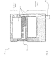
- the motor controller 20 includes a generally hollow motor control housing 22 within which one or more heat generating components 24 are mounted.
- the heat generating components 24 include, but are not limited to, a printed wire board (PWB), capacitor, inverter module, an insulated gate bipolar transistor (IGBT), bus bar, and inductor for example.
- PWB printed wire board
- IGBT insulated gate bipolar transistor
- the air cooling system 30 of the motor controller 20 includes a cooling device 32 extending between a first end 26 and a second, opposite end 28 of the motor control housing 22.
- the cooling device 32 is a cold plate.
- the cold plate 32 comprises a first and second substantially planar plate 34, 36 arranged generally parallel to one another and separated from each other by a distance.
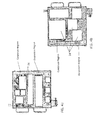
- At least one fluid passage 38 (see FIG. 2 ) is defined within the gap formed between the first and second plates 34, 36 such that a fluid F may flow between the first and second ends 40, 42 of the cold plate 32.
- a fluid inlet 44 is arranged in communication with the at least one fluid passage 38 for supplying a desired amount of fluid F to the interior of the cold plate 32.
- the fluid inlet 44 is sealed such that the total amount of fluid F within the cold plate 32 remains constant during operation of the motor controller 20.
- the fluid F sealed within the cold plate 32 may have a lowered boiling temperature compared to the fluid used in a conventional cold plate, such as 72°C for example.
- other fluids commonly used in sealed systems are within the scope of the disclosure.
- the fluid sealed within the cold plate 32 is configured to cycle between a liquid and a vapor to remove heat from the motor controller 20.
- a cooling system 30 of the motor controller 20 using another cooling device 32, such as a heat pipe for example, is also within the scope of the disclosure.
- a portion of the cold plate 32 is defined as an evaporator region.
- heat is transferred to a liquid portion of the fluid disposed therein, causing the liquid to vaporize.
- another portion of the cold plate 32 for example adjacent the first end 40 of the cold plate 32, may be defined as a condenser region.
- heat is released from the vaporized portion of the fluid, causing the vapor to condense to a liquid.
- fins may be attached to the cold plate surfaces 34 and 36, disposed between the cold plate surfaces and the housing, to enhance heat transfer for a condenser (see FIG. 1 ).
- a plurality of fins may form a fin core 50 configured to enhance the heat transferability of the cold plate 32. More specifically, the fin core 50 may be interposed between at least a portion of the first and second plate 34, 36. In one embodiment, the portion of the fin core 50 arranged within the evaporator region of the cold plate 32 has a high fin density.
- a high fin density may be defined as a fin/distance ratio between about 18-25 fins/inch or greater.
- the heat generating components 24 of the motor controller 20 are mounted at various positions to one or both of the first plate 34 and the second plate 36 of the cold plate 32.
- the components 24 configured to produce the greatest amount of heat are arranged within the evaporator region of the cold plate 32, near the second end 42 thereof, to maximize the amount of heat transferred to the liquid portion of the fluid F within the cold plate 32.
- the positioning of the components 24 and the configuration of the cold plate 32 will vary based on a given application and the amount of heat to be dissipated.
- one or more openings are formed in both the first end 26 and the second end 28 of the motor control housing 22 to define an air flow channel 60 between each of the first and second plates 34, 36 and an adjacent sidewall 52, 54 of the housing 22, respectively.
- cool inlet air A such as provided by a fan for example
- inlet duct or plenum 62 is fed via an inlet duct or plenum 62 through the one or more openings (not shown) formed in the first end 26 of the housing 22.
- This air flow convectively cools the plurality of heat generating components 24 within the motor housing 22.
- Warmer air is similarly output from the motor control housing 22, such as to an outlet plenum or duct 64 coupled thereto, via the plurality of openings (not shown) formed in the second end 28 of the housing 22.
- the heat generated by the plurality of components 24 mounted to the cold plate 32 also conducts through the first and second plates 34, 36, respectively, to the fluid F trapped within the interior of the cold plate 32.
- a portion of the fluid F in a liquid phase is arranged near the second end 42 of the cold plate 32.
- the liquid within the evaporator region vaporizes and travels through the one or more fluid passages 38 to the condensing region, near the first end 52 of the cold plate 32.
- a portion of the cool air A provided at the first end 26 of the motor housing 22 is configured to conductively cool the vaporized fluid within the condenser region via the first and second plates 34, 36.
- the heat transfer that occurs between the vaporized fluid and the cool air A causes the vaporized fluid to cool and condense into a liquid which then moves through the fluid passage 38, such as due to gravity for example, back to the second end 42 of the cold plate 32.
- An air cooled motor controller 20 as described herein enables the use of a liquid-cooled motor controller in additional applications where a power electronics cooling system is not available on an aircraft. Only thermal modifications need be completed to adapt the motor controller from a liquid cooled application to an air cooled application.
- the air cooled motor controller 20 disclosed herein results in an improved heat transfer such that other components previously configured to enhance the heat transfer of the system, for example an inductor housing, may be eliminated resulting in both a weight and cost reduction.
Landscapes
- Engineering & Computer Science (AREA)
- Microelectronics & Electronic Packaging (AREA)
- Physics & Mathematics (AREA)
- Thermal Sciences (AREA)
- Aviation & Aerospace Engineering (AREA)
- Motor Or Generator Cooling System (AREA)
Applications Claiming Priority (1)
| Application Number | Priority Date | Filing Date | Title |
|---|---|---|---|
| US14/728,037 US10201119B2 (en) | 2015-06-02 | 2015-06-02 | System and method of alternate cooling of a liquid cooled motor controller |
Publications (2)
| Publication Number | Publication Date |
|---|---|
| EP3102013A1 true EP3102013A1 (fr) | 2016-12-07 |
| EP3102013B1 EP3102013B1 (fr) | 2020-05-06 |
Family
ID=56360156
Family Applications (1)
| Application Number | Title | Priority Date | Filing Date |
|---|---|---|---|
| EP16172689.8A Active EP3102013B1 (fr) | 2015-06-02 | 2016-06-02 | Système et procédé de refroidissement alternés d'un contrôleur de moteur refroidi par liquide |
Country Status (2)
| Country | Link |
|---|---|
| US (1) | US10201119B2 (fr) |
| EP (1) | EP3102013B1 (fr) |
Cited By (3)
| Publication number | Priority date | Publication date | Assignee | Title |
|---|---|---|---|---|
| CN107591262A (zh) * | 2017-11-03 | 2018-01-16 | 常熟开关制造有限公司(原常熟开关厂) | 控制与保护开关 |
| CN108541194A (zh) * | 2018-05-31 | 2018-09-14 | 湖北省雄雄电子科技有限公司 | 一种散热性能好的电动车控制器 |
| US12557245B1 (en) * | 2022-09-27 | 2026-02-17 | International Business Machines Corporation | Dual-phase evaporative cooling in sealed electronics devices |
Families Citing this family (5)
| Publication number | Priority date | Publication date | Assignee | Title |
|---|---|---|---|---|
| US11166397B2 (en) * | 2018-02-02 | 2021-11-02 | Toshiba Mitsubishi—Electric Industrial Systems Corporation | Power conversion device |
| CN109883227A (zh) * | 2019-01-29 | 2019-06-14 | 株洲智热技术有限公司 | 强化沸腾装置 |
| US11428168B2 (en) | 2020-01-06 | 2022-08-30 | Hamilton Sundstrand Corporation | Starter/generator arrangements for gas turbine engines |
| US11856687B2 (en) * | 2021-12-21 | 2023-12-26 | Semikron Elektronik Gmbh & Co. Kg | Power electronics system having a housing, a cooling device, a power semiconductor module and a capacitor device |
| US12615746B1 (en) | 2025-04-25 | 2026-04-28 | Rtx Corporation | Electric machine cooling plate for aircraft powerplant |
Citations (2)
| Publication number | Priority date | Publication date | Assignee | Title |
|---|---|---|---|---|
| US5283715A (en) * | 1992-09-29 | 1994-02-01 | International Business Machines, Inc. | Integrated heat pipe and circuit board structure |
| US20140321051A1 (en) * | 2013-04-29 | 2014-10-30 | Hewlett-Packard Development Company, L.P. | Shielding Panel Having an Opening for a Heat Sink |
Family Cites Families (13)
| Publication number | Priority date | Publication date | Assignee | Title |
|---|---|---|---|---|
| US4635709A (en) | 1985-12-03 | 1987-01-13 | The United States Of America As Represented By The Secretary Of The Air Force | Dual mode heat exchanger |
| US4944344A (en) | 1988-10-31 | 1990-07-31 | Sundstrand Corporation | Hermetically sealed modular electronic cold plate utilizing reflux cooling |
| US4941530A (en) | 1989-01-13 | 1990-07-17 | Sundstrand Corporation | Enhanced air fin cooling arrangement for a hermetically sealed modular electronic cold plate utilizing reflux cooling |
| DE19709934B4 (de) * | 1996-03-14 | 2008-04-17 | Denso Corp., Kariya | Kühlgerät zum Sieden und Kondensieren eines Kältemittels |
| US7861408B2 (en) * | 2005-06-07 | 2011-01-04 | Wolverine Tube, Inc. | Heat transfer surface for electronic cooling |
| US20080087456A1 (en) * | 2006-10-13 | 2008-04-17 | Onscreen Technologies, Inc. | Circuit board assemblies with combined fluid-containing heatspreader-ground plane and methods therefor |
| DE102008004053A1 (de) | 2008-01-11 | 2009-07-23 | Airbus Deutschland Gmbh | Spitzenlast-Kühlung von elektronischen Bauteilen durch phasenwechselnde Materialien |
| JP4706754B2 (ja) * | 2008-12-24 | 2011-06-22 | ソニー株式会社 | 熱輸送デバイス及び電子機器 |
| US8300412B2 (en) | 2010-09-30 | 2012-10-30 | Hamilton Sundstrand Corporation | Heat exchanger for motor controller |
| US8634193B2 (en) * | 2011-12-05 | 2014-01-21 | Rockwell Automation Technologies, Inc. | Device and method using induction to improve natural convection cooling |
| US9175694B2 (en) | 2012-03-20 | 2015-11-03 | Hamilton Sundstrand Corporation | Air cooled motor controllers |
| JP5836909B2 (ja) * | 2012-09-27 | 2015-12-24 | ファナック株式会社 | モータ駆動装置および制御盤 |
| EP2819279B1 (fr) * | 2013-06-27 | 2017-01-18 | ABB Research Ltd. | Systeme de refroidissement |
-
2015
- 2015-06-02 US US14/728,037 patent/US10201119B2/en active Active
-
2016
- 2016-06-02 EP EP16172689.8A patent/EP3102013B1/fr active Active
Patent Citations (2)
| Publication number | Priority date | Publication date | Assignee | Title |
|---|---|---|---|---|
| US5283715A (en) * | 1992-09-29 | 1994-02-01 | International Business Machines, Inc. | Integrated heat pipe and circuit board structure |
| US20140321051A1 (en) * | 2013-04-29 | 2014-10-30 | Hewlett-Packard Development Company, L.P. | Shielding Panel Having an Opening for a Heat Sink |
Cited By (4)
| Publication number | Priority date | Publication date | Assignee | Title |
|---|---|---|---|---|
| CN107591262A (zh) * | 2017-11-03 | 2018-01-16 | 常熟开关制造有限公司(原常熟开关厂) | 控制与保护开关 |
| CN107591262B (zh) * | 2017-11-03 | 2020-02-07 | 常熟开关制造有限公司(原常熟开关厂) | 控制与保护开关 |
| CN108541194A (zh) * | 2018-05-31 | 2018-09-14 | 湖北省雄雄电子科技有限公司 | 一种散热性能好的电动车控制器 |
| US12557245B1 (en) * | 2022-09-27 | 2026-02-17 | International Business Machines Corporation | Dual-phase evaporative cooling in sealed electronics devices |
Also Published As
| Publication number | Publication date |
|---|---|
| EP3102013B1 (fr) | 2020-05-06 |
| US20160360643A1 (en) | 2016-12-08 |
| US10201119B2 (en) | 2019-02-05 |
Similar Documents
| Publication | Publication Date | Title |
|---|---|---|
| EP3102013B1 (fr) | Système et procédé de refroidissement alternés d'un contrôleur de moteur refroidi par liquide | |
| US9560790B2 (en) | Power electronics cooling system with two-phase cooler | |
| EP2645040B1 (fr) | Échangeur de chaleur pour convertisseurs de traction | |
| US9437523B2 (en) | Two-sided jet impingement assemblies and power electronics modules comprising the same | |
| CA2820330C (fr) | Systeme de refroidissement a deux phases pour composants electroniques | |
| EP2171385B1 (fr) | Système de refroidissement auxiliaire | |
| EP2469996A2 (fr) | Dispositif de refroidissement et dispositif de conversion de puissance l'incluant | |
| US20060243422A1 (en) | Liquid-cooled semiconductor unit for cooling high-power semiconductor elements that are enclosed in modules | |
| CN105940279A (zh) | 冷却装置和具有它的数据中心 | |
| EP3026990B1 (fr) | Appareil | |
| US8300412B2 (en) | Heat exchanger for motor controller | |
| JP4666084B2 (ja) | 電車用の電力変換装置 | |
| CN101416373B (zh) | 电力变换装置 | |
| CN101459375B (zh) | 牵引变流装置 | |
| JP2013016589A (ja) | 沸騰冷却装置及び沸騰冷却装置を用いた車両用冷却システム | |
| JP2015156411A (ja) | 電力変換装置およびそれを搭載した鉄道車両 | |
| CN202663701U (zh) | 用于冷却电子元件的设备以及发电机所用的电子控制设备 | |
| EP2640176B1 (fr) | Refroidissement par convection de cycle de vapeur de l'électronique | |
| US11134585B2 (en) | Aircraft power electronic unit and method of cooling | |
| CN213638697U (zh) | 一种发热器件冷却装置及电控设备 | |
| CN113784570A (zh) | 热电联供机器 | |
| JP5887479B2 (ja) | 冷却装置およびこれを搭載した電子機器、および電気自動車 | |
| TWI909836B (zh) | 散熱模組、與散熱系統 | |
| Vetrovec et al. | Progress in the development of a high-performance heat sink for hybrid electric vehicle inverters | |
| JP2010027760A (ja) | 電気装置 |
Legal Events
| Date | Code | Title | Description |
|---|---|---|---|
| PUAI | Public reference made under article 153(3) epc to a published international application that has entered the european phase |
Free format text: ORIGINAL CODE: 0009012 |
|
| STAA | Information on the status of an ep patent application or granted ep patent |
Free format text: STATUS: THE APPLICATION HAS BEEN PUBLISHED |
|
| AK | Designated contracting states |
Kind code of ref document: A1 Designated state(s): AL AT BE BG CH CY CZ DE DK EE ES FI FR GB GR HR HU IE IS IT LI LT LU LV MC MK MT NL NO PL PT RO RS SE SI SK SM TR |
|
| AX | Request for extension of the european patent |
Extension state: BA ME |
|
| STAA | Information on the status of an ep patent application or granted ep patent |
Free format text: STATUS: REQUEST FOR EXAMINATION WAS MADE |
|
| 17P | Request for examination filed |
Effective date: 20170607 |
|
| RBV | Designated contracting states (corrected) |
Designated state(s): AL AT BE BG CH CY CZ DE DK EE ES FI FR GB GR HR HU IE IS IT LI LT LU LV MC MK MT NL NO PL PT RO RS SE SI SK SM TR |
|
| STAA | Information on the status of an ep patent application or granted ep patent |
Free format text: STATUS: EXAMINATION IS IN PROGRESS |
|
| 17Q | First examination report despatched |
Effective date: 20190206 |
|
| GRAP | Despatch of communication of intention to grant a patent |
Free format text: ORIGINAL CODE: EPIDOSNIGR1 |
|
| STAA | Information on the status of an ep patent application or granted ep patent |
Free format text: STATUS: GRANT OF PATENT IS INTENDED |
|
| INTG | Intention to grant announced |
Effective date: 20191217 |
|
| GRAS | Grant fee paid |
Free format text: ORIGINAL CODE: EPIDOSNIGR3 |
|
| GRAA | (expected) grant |
Free format text: ORIGINAL CODE: 0009210 |
|
| STAA | Information on the status of an ep patent application or granted ep patent |
Free format text: STATUS: THE PATENT HAS BEEN GRANTED |
|
| AK | Designated contracting states |
Kind code of ref document: B1 Designated state(s): AL AT BE BG CH CY CZ DE DK EE ES FI FR GB GR HR HU IE IS IT LI LT LU LV MC MK MT NL NO PL PT RO RS SE SI SK SM TR |
|
| REG | Reference to a national code |
Ref country code: GB Ref legal event code: FG4D |
|
| REG | Reference to a national code |
Ref country code: CH Ref legal event code: EP Ref country code: AT Ref legal event code: REF Ref document number: 1268961 Country of ref document: AT Kind code of ref document: T Effective date: 20200515 |
|
| REG | Reference to a national code |
Ref country code: IE Ref legal event code: FG4D |
|
| REG | Reference to a national code |
Ref country code: DE Ref legal event code: R096 Ref document number: 602016035531 Country of ref document: DE |
|
| REG | Reference to a national code |
Ref country code: LT Ref legal event code: MG4D |
|
| REG | Reference to a national code |
Ref country code: NL Ref legal event code: MP Effective date: 20200506 |
|
| PG25 | Lapsed in a contracting state [announced via postgrant information from national office to epo] |
Ref country code: NO Free format text: LAPSE BECAUSE OF FAILURE TO SUBMIT A TRANSLATION OF THE DESCRIPTION OR TO PAY THE FEE WITHIN THE PRESCRIBED TIME-LIMIT Effective date: 20200806 Ref country code: GR Free format text: LAPSE BECAUSE OF FAILURE TO SUBMIT A TRANSLATION OF THE DESCRIPTION OR TO PAY THE FEE WITHIN THE PRESCRIBED TIME-LIMIT Effective date: 20200807 Ref country code: LT Free format text: LAPSE BECAUSE OF FAILURE TO SUBMIT A TRANSLATION OF THE DESCRIPTION OR TO PAY THE FEE WITHIN THE PRESCRIBED TIME-LIMIT Effective date: 20200506 Ref country code: SE Free format text: LAPSE BECAUSE OF FAILURE TO SUBMIT A TRANSLATION OF THE DESCRIPTION OR TO PAY THE FEE WITHIN THE PRESCRIBED TIME-LIMIT Effective date: 20200506 Ref country code: PT Free format text: LAPSE BECAUSE OF FAILURE TO SUBMIT A TRANSLATION OF THE DESCRIPTION OR TO PAY THE FEE WITHIN THE PRESCRIBED TIME-LIMIT Effective date: 20200907 Ref country code: IS Free format text: LAPSE BECAUSE OF FAILURE TO SUBMIT A TRANSLATION OF THE DESCRIPTION OR TO PAY THE FEE WITHIN THE PRESCRIBED TIME-LIMIT Effective date: 20200906 Ref country code: FI Free format text: LAPSE BECAUSE OF FAILURE TO SUBMIT A TRANSLATION OF THE DESCRIPTION OR TO PAY THE FEE WITHIN THE PRESCRIBED TIME-LIMIT Effective date: 20200506 |
|
| PG25 | Lapsed in a contracting state [announced via postgrant information from national office to epo] |
Ref country code: HR Free format text: LAPSE BECAUSE OF FAILURE TO SUBMIT A TRANSLATION OF THE DESCRIPTION OR TO PAY THE FEE WITHIN THE PRESCRIBED TIME-LIMIT Effective date: 20200506 Ref country code: LV Free format text: LAPSE BECAUSE OF FAILURE TO SUBMIT A TRANSLATION OF THE DESCRIPTION OR TO PAY THE FEE WITHIN THE PRESCRIBED TIME-LIMIT Effective date: 20200506 Ref country code: BG Free format text: LAPSE BECAUSE OF FAILURE TO SUBMIT A TRANSLATION OF THE DESCRIPTION OR TO PAY THE FEE WITHIN THE PRESCRIBED TIME-LIMIT Effective date: 20200806 Ref country code: RS Free format text: LAPSE BECAUSE OF FAILURE TO SUBMIT A TRANSLATION OF THE DESCRIPTION OR TO PAY THE FEE WITHIN THE PRESCRIBED TIME-LIMIT Effective date: 20200506 |
|
| REG | Reference to a national code |
Ref country code: AT Ref legal event code: MK05 Ref document number: 1268961 Country of ref document: AT Kind code of ref document: T Effective date: 20200506 |
|
| PG25 | Lapsed in a contracting state [announced via postgrant information from national office to epo] |
Ref country code: AL Free format text: LAPSE BECAUSE OF FAILURE TO SUBMIT A TRANSLATION OF THE DESCRIPTION OR TO PAY THE FEE WITHIN THE PRESCRIBED TIME-LIMIT Effective date: 20200506 Ref country code: NL Free format text: LAPSE BECAUSE OF FAILURE TO SUBMIT A TRANSLATION OF THE DESCRIPTION OR TO PAY THE FEE WITHIN THE PRESCRIBED TIME-LIMIT Effective date: 20200506 |
|
| PG25 | Lapsed in a contracting state [announced via postgrant information from national office to epo] |
Ref country code: CZ Free format text: LAPSE BECAUSE OF FAILURE TO SUBMIT A TRANSLATION OF THE DESCRIPTION OR TO PAY THE FEE WITHIN THE PRESCRIBED TIME-LIMIT Effective date: 20200506 Ref country code: RO Free format text: LAPSE BECAUSE OF FAILURE TO SUBMIT A TRANSLATION OF THE DESCRIPTION OR TO PAY THE FEE WITHIN THE PRESCRIBED TIME-LIMIT Effective date: 20200506 Ref country code: ES Free format text: LAPSE BECAUSE OF FAILURE TO SUBMIT A TRANSLATION OF THE DESCRIPTION OR TO PAY THE FEE WITHIN THE PRESCRIBED TIME-LIMIT Effective date: 20200506 Ref country code: SM Free format text: LAPSE BECAUSE OF FAILURE TO SUBMIT A TRANSLATION OF THE DESCRIPTION OR TO PAY THE FEE WITHIN THE PRESCRIBED TIME-LIMIT Effective date: 20200506 Ref country code: EE Free format text: LAPSE BECAUSE OF FAILURE TO SUBMIT A TRANSLATION OF THE DESCRIPTION OR TO PAY THE FEE WITHIN THE PRESCRIBED TIME-LIMIT Effective date: 20200506 Ref country code: DK Free format text: LAPSE BECAUSE OF FAILURE TO SUBMIT A TRANSLATION OF THE DESCRIPTION OR TO PAY THE FEE WITHIN THE PRESCRIBED TIME-LIMIT Effective date: 20200506 Ref country code: AT Free format text: LAPSE BECAUSE OF FAILURE TO SUBMIT A TRANSLATION OF THE DESCRIPTION OR TO PAY THE FEE WITHIN THE PRESCRIBED TIME-LIMIT Effective date: 20200506 Ref country code: IT Free format text: LAPSE BECAUSE OF FAILURE TO SUBMIT A TRANSLATION OF THE DESCRIPTION OR TO PAY THE FEE WITHIN THE PRESCRIBED TIME-LIMIT Effective date: 20200506 |
|
| REG | Reference to a national code |
Ref country code: CH Ref legal event code: PL |
|
| REG | Reference to a national code |
Ref country code: DE Ref legal event code: R097 Ref document number: 602016035531 Country of ref document: DE |
|
| PG25 | Lapsed in a contracting state [announced via postgrant information from national office to epo] |
Ref country code: MC Free format text: LAPSE BECAUSE OF FAILURE TO SUBMIT A TRANSLATION OF THE DESCRIPTION OR TO PAY THE FEE WITHIN THE PRESCRIBED TIME-LIMIT Effective date: 20200506 Ref country code: SK Free format text: LAPSE BECAUSE OF FAILURE TO SUBMIT A TRANSLATION OF THE DESCRIPTION OR TO PAY THE FEE WITHIN THE PRESCRIBED TIME-LIMIT Effective date: 20200506 Ref country code: PL Free format text: LAPSE BECAUSE OF FAILURE TO SUBMIT A TRANSLATION OF THE DESCRIPTION OR TO PAY THE FEE WITHIN THE PRESCRIBED TIME-LIMIT Effective date: 20200506 |
|
| PLBE | No opposition filed within time limit |
Free format text: ORIGINAL CODE: 0009261 |
|
| STAA | Information on the status of an ep patent application or granted ep patent |
Free format text: STATUS: NO OPPOSITION FILED WITHIN TIME LIMIT |
|
| PG25 | Lapsed in a contracting state [announced via postgrant information from national office to epo] |
Ref country code: LU Free format text: LAPSE BECAUSE OF NON-PAYMENT OF DUE FEES Effective date: 20200602 |
|
| 26N | No opposition filed |
Effective date: 20210209 |
|
| REG | Reference to a national code |
Ref country code: BE Ref legal event code: MM Effective date: 20200630 |
|
| PG25 | Lapsed in a contracting state [announced via postgrant information from national office to epo] |
Ref country code: LI Free format text: LAPSE BECAUSE OF NON-PAYMENT OF DUE FEES Effective date: 20200630 Ref country code: CH Free format text: LAPSE BECAUSE OF NON-PAYMENT OF DUE FEES Effective date: 20200630 Ref country code: IE Free format text: LAPSE BECAUSE OF NON-PAYMENT OF DUE FEES Effective date: 20200602 |
|
| PG25 | Lapsed in a contracting state [announced via postgrant information from national office to epo] |
Ref country code: SI Free format text: LAPSE BECAUSE OF FAILURE TO SUBMIT A TRANSLATION OF THE DESCRIPTION OR TO PAY THE FEE WITHIN THE PRESCRIBED TIME-LIMIT Effective date: 20200506 Ref country code: BE Free format text: LAPSE BECAUSE OF NON-PAYMENT OF DUE FEES Effective date: 20200630 |
|
| PG25 | Lapsed in a contracting state [announced via postgrant information from national office to epo] |
Ref country code: TR Free format text: LAPSE BECAUSE OF FAILURE TO SUBMIT A TRANSLATION OF THE DESCRIPTION OR TO PAY THE FEE WITHIN THE PRESCRIBED TIME-LIMIT Effective date: 20200506 Ref country code: MT Free format text: LAPSE BECAUSE OF FAILURE TO SUBMIT A TRANSLATION OF THE DESCRIPTION OR TO PAY THE FEE WITHIN THE PRESCRIBED TIME-LIMIT Effective date: 20200506 Ref country code: CY Free format text: LAPSE BECAUSE OF FAILURE TO SUBMIT A TRANSLATION OF THE DESCRIPTION OR TO PAY THE FEE WITHIN THE PRESCRIBED TIME-LIMIT Effective date: 20200506 |
|
| PG25 | Lapsed in a contracting state [announced via postgrant information from national office to epo] |
Ref country code: MK Free format text: LAPSE BECAUSE OF FAILURE TO SUBMIT A TRANSLATION OF THE DESCRIPTION OR TO PAY THE FEE WITHIN THE PRESCRIBED TIME-LIMIT Effective date: 20200506 |
|
| P01 | Opt-out of the competence of the unified patent court (upc) registered |
Effective date: 20230522 |
|
| PGFP | Annual fee paid to national office [announced via postgrant information from national office to epo] |
Ref country code: DE Payment date: 20250520 Year of fee payment: 10 |
|
| PGFP | Annual fee paid to national office [announced via postgrant information from national office to epo] |
Ref country code: GB Payment date: 20250520 Year of fee payment: 10 |
|
| PGFP | Annual fee paid to national office [announced via postgrant information from national office to epo] |
Ref country code: FR Payment date: 20250520 Year of fee payment: 10 |