EP3102888B1 - Brûleur à gaz, arrangement de brûleurs à gaz, poste de cuisson, et cuisinière - Google Patents
Brûleur à gaz, arrangement de brûleurs à gaz, poste de cuisson, et cuisinière Download PDFInfo
- Publication number
- EP3102888B1 EP3102888B1 EP15706931.1A EP15706931A EP3102888B1 EP 3102888 B1 EP3102888 B1 EP 3102888B1 EP 15706931 A EP15706931 A EP 15706931A EP 3102888 B1 EP3102888 B1 EP 3102888B1
- Authority
- EP
- European Patent Office
- Prior art keywords
- gas
- burner
- gas burner
- valve
- head
- Prior art date
- Legal status (The legal status is an assumption and is not a legal conclusion. Google has not performed a legal analysis and makes no representation as to the accuracy of the status listed.)
- Active
Links
- 239000007789 gas Substances 0.000 claims description 203
- 239000002737 fuel gas Substances 0.000 claims description 30
- 238000010411 cooking Methods 0.000 claims description 20
- 239000000203 mixture Substances 0.000 claims description 9
- 238000012544 monitoring process Methods 0.000 claims description 3
- 230000001105 regulatory effect Effects 0.000 claims description 2
- 238000005553 drilling Methods 0.000 description 4
- 101000793686 Homo sapiens Azurocidin Proteins 0.000 description 3
- 238000007792 addition Methods 0.000 description 1
- 239000000567 combustion gas Substances 0.000 description 1
- 230000006835 compression Effects 0.000 description 1
- 238000007906 compression Methods 0.000 description 1
- 238000013016 damping Methods 0.000 description 1
- 230000001934 delay Effects 0.000 description 1
- 230000003111 delayed effect Effects 0.000 description 1
- 238000006073 displacement reaction Methods 0.000 description 1
Images


Classifications
-
- F—MECHANICAL ENGINEERING; LIGHTING; HEATING; WEAPONS; BLASTING
- F24—HEATING; RANGES; VENTILATING
- F24C—DOMESTIC STOVES OR RANGES ; DETAILS OF DOMESTIC STOVES OR RANGES, OF GENERAL APPLICATION
- F24C3/00—Stoves or ranges for gaseous fuels
- F24C3/10—Arrangement or mounting of ignition devices
-
- F—MECHANICAL ENGINEERING; LIGHTING; HEATING; WEAPONS; BLASTING
- F24—HEATING; RANGES; VENTILATING
- F24C—DOMESTIC STOVES OR RANGES ; DETAILS OF DOMESTIC STOVES OR RANGES, OF GENERAL APPLICATION
- F24C3/00—Stoves or ranges for gaseous fuels
- F24C3/08—Arrangement or mounting of burners
- F24C3/085—Arrangement or mounting of burners on ranges
-
- F—MECHANICAL ENGINEERING; LIGHTING; HEATING; WEAPONS; BLASTING
- F24—HEATING; RANGES; VENTILATING
- F24C—DOMESTIC STOVES OR RANGES ; DETAILS OF DOMESTIC STOVES OR RANGES, OF GENERAL APPLICATION
- F24C3/00—Stoves or ranges for gaseous fuels
- F24C3/12—Arrangement or mounting of control or safety devices
- F24C3/122—Arrangement or mounting of control or safety devices on stoves
-
- F—MECHANICAL ENGINEERING; LIGHTING; HEATING; WEAPONS; BLASTING
- F24—HEATING; RANGES; VENTILATING
- F24C—DOMESTIC STOVES OR RANGES ; DETAILS OF DOMESTIC STOVES OR RANGES, OF GENERAL APPLICATION
- F24C3/00—Stoves or ranges for gaseous fuels
- F24C3/12—Arrangement or mounting of control or safety devices
- F24C3/126—Arrangement or mounting of control or safety devices on ranges
-
- F—MECHANICAL ENGINEERING; LIGHTING; HEATING; WEAPONS; BLASTING
- F23—COMBUSTION APPARATUS; COMBUSTION PROCESSES
- F23D—BURNERS
- F23D2209/00—Safety arrangements
Definitions
- the present invention relates to a gas burner, a gas burner arrangement, a hotplate and a stove.
- the DE 103 55 455 A1 describes a hob with a variety of gas burners.
- Each gas burner has a burner head which can be displaced with respect to a burner housing.
- Each gas burner is assigned a gas shut-off valve, which can either be closed or opened by moving the burner head.
- the fuel gas and primary air are mixed simultaneously at the same gas feed line of the gas burners.
- the US 2,456,864 A describes a gas burner that includes a centrally located stamp. When a cooking container is placed on the gas burner, the stamp is pressed down and a fuel gas inflow to the gas burner is released.
- the DE 68 869 C describes a gas burner that is pivotable relative to a gas supply line. When a food container is placed on the gas burner, it pivots in such a way that a fuel gas flow to the gas burner is released with the aid of a gas valve.
- the EP 2 495 498 A1 describes a gas burner with a central plunger. When a food container is placed on the gas burner, the tappet is pressed down and a fuel gas flow to the gas burner is released.
- an object of the present invention is to provide an improved gas burner.
- a gas burner for a hotplate with a gas shutoff valve a burner housing which can be fastened to a gas feed line of the gas burner, and a burner head which can be displaced relative to the burner housing is proposed.
- the burner head can be shifted from an open position into a closed position, the burner head being in the direction of Closing position is biased by means of a spring device and wherein the burner housing and / or the burner head has at least one primary air supply opening for supplying primary air into a mixing chamber of the gas burner.
- the gas shutoff valve has a valve body which is accommodated at least in sections in the burner head, the valve body having at least one radially arranged fuel gas inlet opening.
- the gas burner has a thermocouple for flame monitoring.
- thermocouple is in particular coupled to a gas control valve of the gas burner, so that when the burner flame is extinguished, the gas control valve is closed, so that no more fuel gas flows to the gas burner.
- the gas burner can also have an ignition element for igniting the primary air / fuel gas mixture.
- the burner housing is set up to at least partially encompass the gas supply line.
- the burner housing has, in particular, at least two gripping arms arranged opposite one another, which preferably grip the gas supply line in a form-fitting manner.
- the burner housing can be clamped to the gas feed line.
- the burner head has a support surface for placing a cooking vessel on the gas burner.
- the contact surface is in particular an end face of the burner head. This means that there is no need for an additional pan support.
- the burner head can be shifted from the closed position into the open position against the spring force of the spring device when the cooking container is placed on the support surface.
- the gas shut-off valve is simply opened by placing the food container on the burner head.
- the burner head can be displaced from the open position into the closed position when the product container is lifted from the support surface with the aid of the spring device.
- a damping or delay element can be provided, which leaves the gas shut-off valve for a predetermined period of time, for example for a few fractions of seconds to seconds, in particular at least 1, 2 or 3 seconds, in the open position when the product to be cooked is lifted off, so that when the food container is lifted off the gas burner, the gas supply is not immediately switched off.
- the delay element delays or brakes the automatic displacement of the burner head from the open position to the closed position, such that the gas shutoff valve is closed with a time delay.
- the gas shutoff valve has a valve body which is accommodated at least in sections in the burner head, the valve body having at least one radially arranged fuel gas inlet opening.
- the valve body is preferably tubular and the valve body is received in a nozzle holder of the gas burner.
- the valve body can be screwed into the nozzle holder.
- a gas nozzle of the gas burner is preferably received in the valve body.
- the gas nozzle is set up to inject fuel gas into a mixing chamber of the gas burner.
- the gas shut-off valve has a valve seat corresponding to the valve body, which is provided on the burner housing. In the closed position of the burner head, the at least one radially arranged fuel gas inlet opening can be sealed by the valve seat.
- the valve seat is in particular a cylindrical bore provided in the burner housing.
- the valve seat radially seals the valve body in the closed position.
- the optional delay element is in particular set up to slow down a movement of the burner head when the burner head is moved from the open position to the closed position such that the at least one fuel gas inlet opening is slowly covered by the valve seat and the gas shutoff valve is thereby slowly closed.
- the gas burner has a pressure sensor for recognizing a cooking vessel placed on a support surface of the burner head.
- the pressure sensor is, for example, plate-like or foil-like.
- the pressure sensor preferably supplies a control device with a signal as to whether a cooking vessel is placed on the gas burner or not. If a cooking vessel is placed on the gas burner, a corresponding signal can be sent from the pressure sensor to the control device.
- the control device can then control, for example, an ignition element of the gas burner to ignite a burner flame.
- a gas burner arrangement for a hotplate with at least two such gas burners, a gas feed line and a common gas control valve for regulating a gas volume flow to the at least two gas burners is proposed.
- the gas burner arrangement can have, for example, three or four gas burners.
- the gas burner arrangement has a pressure sensor which is set up to detect a cooking vessel placed on a support surface of the burner head of the gas burner and to output a corresponding output signal to a control device which is set up to trigger an ignition element as a function of the output signal of the pressure sensor ignite the gas burner to ignite a primary air / fuel gas mixture.
- the pressure sensor is operatively connected to the control device.
- the control device is in turn operatively connected to the ignition element.
- the ignition element can be a spark plug.
- the gas burner arrangement has a control device which is set up to control ignition elements of the gas burners in order to ignite a primary air / fuel gas mixture as a function of a signal from a manual switch.
- the hand switch is a button, for example.
- a hotplate with such a gas burner and / or such a gas burner arrangement is also proposed.
- the gas burner, the gas burner arrangement, the hotplate and the cooker are designed in particular for use in the household.
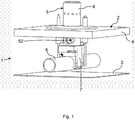
- the Fig. 1 shows a cooker 1 with a hotplate 2.
- the hotplate 2 has a hob 3, which is in particular trough-shaped, and a hob plate 4 arranged at a distance from the hob 3.
- the hotplate 2 also has a gas burner 5 with a burner head 6 and a burner housing 7.
- the burner head 6 is preferably displaceable relative to the burner housing 7.
- the hotplate 2 also has a gas feed line 8 to which the burner housing 7 can be fastened.
- the gas supply line 8 is set up to supply a fuel gas to the gas burner 5.
- the Fig. 2 shows the gas burner 5 in a schematic perspective exploded view.
- the burner housing 7 has a cuboid base body, from the underside of which two gripping arms 9, 10 arranged opposite one another extend.
- the burner housing 7 and in particular the gripping arms 9, 10 are set up to at least partially encompass the gas line 8.
- the gripping arms 9, 10 are set up to clamp the burner housing 7 to the gas feed line.
- An opening 11 is provided on the gas feed line 8, into which a tubular connecting piece 12 of the burner housing 7 projects.
- a film or plate-shaped pressure sensor 14 can be placed on a flat upper side 13 of the burner housing 7.
- the pressure sensor 14 is between the Upper side 13 of the burner housing 7 and an underside 15 of a fastening element 16 are provided.
- the fastening element 16 has a plate-shaped and in particular circular base section 17, which rests on the pressure sensor 14.
- An annular circumferential wall 18 extends out from the top of the base section 17.
- Grooves 19 and 20, respectively, are provided on the outside of the wall on the side and opposite one another and are configured to grip around a thermocouple 21 or an ignition element 22.
- the thermocouple 21 or the ignition element 22 can be clipped into the groove 19 or 20.
- the burner head 6 is in particular tubular and comprises a closed end face which forms a support surface 23 for a food container, not shown. Furthermore, the burner head 6 preferably has a plurality of circumferentially arranged gas nozzles 24, of which in the Fig. 2 only one is provided with a reference number. The gas nozzles 24 are preferably arranged uniformly distributed around a circumference of the burner head 6. At an end section 25 of the burner head 6 facing away from the support surface 23, a bore 26 is provided which breaks through an outer wall of the burner head, in particular twice, 16.
- the gas burner 5 has a nozzle carrier 27 which is accommodated in the burner head 6 at least in sections.
- the nozzle holder 27 is tubular and has a bore 28 which, in an assembled state in which the nozzle holder 27 is received in the burner head 6, is arranged coaxially to the bore 26 of the burner head 6.
- the coaxial bores 26, 28 form a primary air supply opening 52 ( Fig. 1 ) of the gas burner 5.
- Preferably two primary air supply openings 52 arranged opposite one another are provided.
- a cylindrical shoulder 29 extends from an end face of the nozzle carrier 27. The paragraph 29 is arranged facing away from the burner head 6.
- a tubular valve body 30 is inserted.
- the valve body 30 preferably has an external thread 31, with the aid of which the valve body 30 can be screwed into the shoulder 29 of the nozzle carrier 27.
- the valve body 30 has at least one circumferentially arranged fuel gas inlet opening 45. Preferably one is A large number of such fuel gas inlet openings 45 are provided, which are preferably arranged uniformly distributed around a circumference of the valve body 30. An end face of the valve body 30 facing away from the nozzle carrier 27 is closed.
- the gas burner 5 also has a gas nozzle 32 which is attached to the valve body 30.
- the gas nozzle 32 is screwed into the valve body 30.
- the gas burner 5 also has a spring device 33.
- the spring device 33 is in particular a helical or cylindrical spring.
- the spring device 33 is a compression spring.
- the spring device 33 is arranged between the burner housing 7 and the nozzle carrier 27.
- the valve body 30 is received in the spring device 33.
- the spring device 33 is pushed onto the shoulder 29 of the nozzle carrier 27.
- rectangular anti-rotation devices 34 are provided, of which in the Fig. 2 only one is provided with a reference number. The anti-rotation devices 34 prevent the nozzle carrier 27 from rotating relative to the burner head 6.
- the fastening element 16 is preferably screwed to the burner housing 7 by means of screws 35, 36.
- the gas burner 5 also has a cover cap 37 which is set up to rest on the hob plate 4.
- the cover cap 37 preferably has a centrally arranged opening 38 through which the burner head 6 is guided.
- the cover cap 37 has bores 39 and 40, through which the thermocouple 21 and the ignition element 22 can be passed.
- the Fig. 3 shows the gas burner 5 in a schematic sectional view.
- the burner head 6 with the nozzle carrier 27 encloses a mixing chamber 41 of the gas burner 5.
- the mixing chamber 41 is cylindrical.
- the gas nozzle 32 is arranged on a lower end section of the mixing space 41 in such a way that it is set up to inject fuel gas into the mixing space 41.
- the gas nozzle 32 is screwed into the valve body 30, which in turn is screwed into the nozzle holder 27.
- the spring device 33 is arranged between a contact surface 42 of the burner housing 7 and an end surface 43 of the nozzle carrier 27.
- the gas burner 5 also has an in Fig. 3 shown gas shutoff valve 44.
- the gas shutoff valve 44 includes the burner head 6 via the nozzle carrier 27 coupled valve body 30, which has the at least one radially arranged fuel gas inlet opening 45.
- the gas shutoff valve 44 further comprises a valve seat 53 corresponding to the valve body 30 ( Fig. 5 ), which is designed in particular as the inner wall of the connecting piece 12 projecting into the gas supply line 8.
- the gas shut-off valve 44 can be used to selectively close and open one into the Fig. 4 and 5 shown in an open position in the Fig. 3 shown closing position can be shifted.
- the burner head 6 is biased in the direction of the closed position by means of the spring device 33.
- the Fig. 5 shows in an enlarged view by means of arrows the inflow of fuel gas into the gas nozzle 32 in the open position of the burner head 6 or the gas shut-off valve 44.
- the fuel gas flows into the mixing chamber 41.
- primary air is sucked into the mixing chamber 41 through the primary air supply openings 52 on the side. This mixes in the mixing chamber 41 with the fuel gas and exits the burner head 6 through the gas nozzles 24.
- the Fig. 6 shows a gas burner arrangement 47 with three gas burners 5, on which a cooking vessel 46 is placed.
- the burner head 6 is displaced from the closed position into the open position against a spring force F 33 of the spring device 33.
- the burner head 6 can be automatically shifted from the open position into the closed position with the aid of the spring device 33.
- the fuel gas supply is automatically interrupted when the cooking vessel 46 is lifted off the gas burners 5.
- the gas burner 5 can also have a delay element (not shown), which is set up to delay the movement of the burner head 6 from the open position into the closed position such that when the cooking vessel 46 is lifted briefly from the gas burner 5, the gas supply is not delayed, but only with a time delay , for example only after a few fractions of seconds to seconds, for example only after 5 seconds.
- a delay element not shown
- the placement of the food container 46 on the support surface 23 of the burner head 6 can be seen.
- the Fig. 7 shows a schematic view of a further embodiment of a gas burner arrangement 47 for the hotplate 2.
- the gas burner arrangement 47 has at least two gas burners 5, the gas feed line 8 and a common gas control valve 48. With the help of the gas control valve 48, a fuel gas volume flow to the gas burners 5 can be controlled.
- the gas feed line 8 branches after the gas control valve 48 to the gas burners 5.
- the gas control valve 48 is set up to introduce fuel gas into the gas feed line 8 from a main gas line 49.
- a thermocouple 21 and an ignition element 22 are preferably assigned to each of the gas burners 5 of the gas burner arrangement 47.
- the gas burner arrangement 47 can have a control device 50.
- the Fig. 8 shows a further embodiment of a gas burner arrangement 47.
- the control device 50 is operatively connected to the pressure sensors 14 of the gas burner 5, to the thermocouples 21, to the ignition elements 22 and to the gas control valve 48.
- the control device 50 is set up to ignite the corresponding ignition element 22 of the gas burner 5 for igniting the primary air / fuel gas mixture as a function of a signal from the pressure sensor 14 of one of the gas burners 5 when a cooking vessel 46 is placed on the support surface 23 of the burner head 6 of the gas burner 5 becomes.
- the thermocouples 21 are used for flame monitoring on the gas burners 5.
- the Fig. 9 shows a further embodiment of a gas burner arrangement 47.
- the gas burner arrangement 47 according to FIG Fig. 9 has a hand switch 51.
- the hand switch 51 can for example be a push button or button.
- the control device 50 is set up to ignite ignition elements 22 of the gas burners 5 to ignite the primary air / fuel gas mixture as a function of a signal from the hand switch 51. Here, all gas burners 5 are ignited simultaneously. In the gas burners 5 on which no cooking vessel 46 is placed, the respective gas shutoff valve 44 is closed, so that no fuel gas / primary air mixture emerges from these gas burners 5.
Landscapes
- Engineering & Computer Science (AREA)
- Chemical & Material Sciences (AREA)
- Combustion & Propulsion (AREA)
- Mechanical Engineering (AREA)
- General Engineering & Computer Science (AREA)
- Gas Burners (AREA)
Claims (14)
- Brûleur à gaz (5) pour un poste de cuisson (2), avec une vanne de coupure de gaz (44), un carter de brûleur (7) pouvant être fixé à une conduite d'alimentation en gaz (8) du brûleur à gaz (5) et une tête de brûleur (6) déplaçable par rapport au carter de brûleur (7), dans lequel la tête de brûleur (6) est déplaçable pour l'ouverture et la fermeture au choix de la vanne de coupure de gaz (44) d'une position ouverte vers une position fermée, dans lequel la tête de brûleur (6) est précontrainte dans le sens de la position fermée à l'aide d'un dispositif élastique (33), dans lequel le carter de brûleur (7) et/ou la tête de brûleur (6) présente au moins un orifice d'alimentation en air primaire (52) pour l'alimentation en air primaire dans une chambre de mélange (41) du brûleur à gaz (5), dans lequel la vanne de coupure de gaz (44) présente un corps de vanne (30) accueilli au moins par sections dans la tête de brûleur (6), caractérisé en ce que le corps de vanne (30) présente au moins un orifice d'entrée du gaz combustible (45) disposé radialement.
- Brûleur à gaz selon la revendication 1, caractérisé en ce que le brûleur à gaz (5) présente un élément thermique (21) pour la surveillance de la flamme.
- Brûleur à gaz selon la revendication 1 ou 2, caractérisé en ce que le carter de brûleur (7) est aménagé afin d'entourer au moins partiellement la conduite d'alimentation en gaz (8).
- Brûleur à gaz selon l'une des revendications 1 à 3, caractérisé en ce que le carter de brûleur (7) peut être serré à la conduite d'alimentation en gaz (8).
- Brûleur à gaz selon l'une des revendications 1 à 4, caractérisé en ce que la tête de brûleur (6) présente une surface d'appui (23) pour la dépose d'un récipient de denrées à cuire (46) sur le brûleur à gaz (5).
- Brûleur à gaz selon la revendication 5, caractérisé en ce que la tête de brûleur (6) est déplaçable de la position fermée vers la position ouverte à l'encontre d'une force de ressort (F33) du dispositif élastique (33) lors de la dépose du récipient de denrées à cuire (46) sur la surface d'appui (23).
- Brûleur à gaz selon la revendication 5 ou 6, caractérisé en ce que la tête de brûleur (6) est déplaçable de la position ouverte vers la position fermée à l'aide du dispositif élastique (33) lorsque le récipient de denrées à cuire (46) est soulevé de la surface d'appui (23).
- Brûleur à gaz selon l'une des revendications 1 à 7, caractérisé en ce que la vanne de coupure de gaz (44) présente un siège de vanne (53) correspondant au corps de vanne (30), lequel est prévu sur le carter de brûleur (7) et en ce que dans la position fermée de la tête de brûleur (6) l'au moins un orifice d'entrée du gaz combustible (45) disposé radialement peut être étanchéifié par le siège de vanne (53).
- Brûleur à gaz selon l'une des revendications 1 à 8, caractérisé par un capteur de pression (14) pour la détection d'un récipient de denrées à cuire (46) déposé sur la surface d'appui (23) de la tête de brûleur (6).
- Agencement de brûleurs à gaz (47) pour un poste de cuisson (2), avec au moins deux brûleurs à gaz (5) selon l'une des revendications 1 à 9, une conduite d'alimentation en gaz (8) et une vanne de régulation de gaz commune (48) pour la régulation d'un débit volumique de gaz vers les au moins deux brûleurs à gaz (5).
- Agencement de brûleurs à gaz selon la revendication 10, caractérisé par un capteur de pression (14) aménagé afin de détecter un récipient de denrées à cuire (46) déposé sur une surface d'appui (23) de la tête de brûleur (6) du brûleur à gaz (5) et afin d'émettre un signal de sortie correspondant vers un dispositif de commande (50) aménagé afin d'allumer en fonction du signal du capteur de pression (14) un élément d'allumage (22) du brûleur à gaz (5) pour enflammer un mélange air primaire-gaz combustible.
- Agencement de brûleurs à gaz selon la revendication 11, caractérisé par un dispositif de commande (50) aménagé afin de commander en fonction d'un signal d'un commutateur manuel (51) des éléments d'allumage (22) du brûleur à gaz (5) pour enflammer un mélange air primaire-gaz combustible.
- Poste de cuisson (2) avec un brûleur à gaz (5) selon l'une des revendications 1 à 9 et/ou un agencement de brûleurs à gaz (47) selon l'une des revendications 10 à 12.
- Cuisinière (1) avec un brûleur à gaz (5) selon l'une des revendications 1 à 9, un agencement de brûleurs à gaz (47) selon l'une des revendications 10 à 12 et/ou un poste de cuisson (2) selon la revendication 13.
Applications Claiming Priority (2)
| Application Number | Priority Date | Filing Date | Title |
|---|---|---|---|
| ES201430130A ES2542253B1 (es) | 2014-02-03 | 2014-02-03 | Quemador de gas, disposición de quemadores de gas, punto de cocción, y cocina |
| PCT/IB2015/050457 WO2015114491A1 (fr) | 2014-02-03 | 2015-01-21 | Brûleur à gaz, ensemble brûleur à gaz, poste de cuisson et cuisinière |
Publications (2)
| Publication Number | Publication Date |
|---|---|
| EP3102888A1 EP3102888A1 (fr) | 2016-12-14 |
| EP3102888B1 true EP3102888B1 (fr) | 2020-04-29 |
Family
ID=52595373
Family Applications (1)
| Application Number | Title | Priority Date | Filing Date |
|---|---|---|---|
| EP15706931.1A Active EP3102888B1 (fr) | 2014-02-03 | 2015-01-21 | Brûleur à gaz, arrangement de brûleurs à gaz, poste de cuisson, et cuisinière |
Country Status (3)
| Country | Link |
|---|---|
| EP (1) | EP3102888B1 (fr) |
| ES (1) | ES2542253B1 (fr) |
| WO (1) | WO2015114491A1 (fr) |
Family Cites Families (7)
| Publication number | Priority date | Publication date | Assignee | Title |
|---|---|---|---|---|
| DE68869C (de) * | J. SCHÄRFER in Krefeld, Ritterstr. 212 | . Gaskocher mit schwingendem, sich selbsttätig' einstellendem Brenner | ||
| US2234550A (en) * | 1939-03-11 | 1941-03-11 | Ruth Henry | Automatic fuel burner |
| US2456864A (en) * | 1945-07-24 | 1948-12-21 | Cole Frank Bruce | Gas flame regulator |
| GB739738A (en) * | 1953-09-14 | 1955-11-02 | Robertshaw Fulton Controls Co | Combination controls for fluid fuel burning appliances |
| FR2238101B1 (fr) * | 1973-07-18 | 1978-01-27 | Robertshaw Controls Co | |
| DE10355455A1 (de) | 2002-12-12 | 2004-10-07 | BSH Bosch und Siemens Hausgeräte GmbH | Gaskochstelle sowie Verfahren zum Betrieb einer Gaskochstelle |
| DE102011005001A1 (de) * | 2011-03-02 | 2012-09-06 | E.G.O. Elektro-Gerätebau GmbH | Gaskochgerät und Verfahren zum Betrieb eines solchen Gaskochgerätes |
-
2014
- 2014-02-03 ES ES201430130A patent/ES2542253B1/es not_active Expired - Fee Related
-
2015
- 2015-01-21 EP EP15706931.1A patent/EP3102888B1/fr active Active
- 2015-01-21 WO PCT/IB2015/050457 patent/WO2015114491A1/fr not_active Ceased
Non-Patent Citations (1)
| Title |
|---|
| None * |
Also Published As
| Publication number | Publication date |
|---|---|
| ES2542253B1 (es) | 2016-05-17 |
| EP3102888A1 (fr) | 2016-12-14 |
| ES2542253A1 (es) | 2015-08-03 |
| WO2015114491A1 (fr) | 2015-08-06 |
Similar Documents
| Publication | Publication Date | Title |
|---|---|---|
| EP3278025B1 (fr) | Brûleur à gaz et plaque de cuisson à gaz | |
| EP3255341B1 (fr) | Brûleur à gaz et appareil de cuisson ménager | |
| EP3682165B1 (fr) | Brûleur à gaz, dispositif de brûleur à gaz et appareil ménager de cuisson | |
| EP3102888B1 (fr) | Brûleur à gaz, arrangement de brûleurs à gaz, poste de cuisson, et cuisinière | |
| EP3149406B1 (fr) | Soupape de régulation de gaz, table de cuisson et cuisinière à gaz | |
| EP3479022B1 (fr) | Brûleur à gaz et appareil ménager de cuisson | |
| EP1826484B1 (fr) | Dispositif et procédé pour brûler un combustible | |
| EP3679299B1 (fr) | Agencement de brûleur à gaz et appareil de cuisson ménager | |
| EP2952817B1 (fr) | Vanne de gaz avec un système de commande d'un appareil ménager et cuisinière | |
| EP3102879B1 (fr) | Valve de coupure de gaz, ensemble brûleur à gaz, zone de cuisson et cuisinière | |
| EP4199794B1 (fr) | Barbecue ou appareil de cuisson | |
| EP0926437B1 (fr) | Aménagement des brûleurs à gaz pour une surface de cuisson | |
| EP3032370B1 (fr) | Systeme d'utilisation d'un appareil menager, vanne de gaz et cuisiniere | |
| WO2015114490A2 (fr) | Ensemble foyer gaz, plan de cuisson et cuisinière | |
| EP3018409B1 (fr) | Plaque de cuisson avec une partie inférieure de brûleur à gaz | |
| EP3012527A1 (fr) | Poste de cuisson et cuisiniere | |
| DE102018103905B4 (de) | Zweikreis-Gaskochstelle und Verfahren zum Verhindern eines Düsenbrands bei einer Zweikreis-Gaskochstelle | |
| EP2950001B1 (fr) | Plaque de cuisson au gaz et cuisinière | |
| DE673424C (de) | Zuendsicherung fuer gasbeheizte Brat- und Backoefen | |
| DE657191C (de) | Anheizvorrichtung fuer mit fluessigem Brennstoff gespeiste Vergaserlampen, Kocher u. dgl. | |
| DE102013011756A1 (de) | Vorrichtung zum Zünden oder zum Temperaturerfassen eines Gasherdes | |
| DE19932143A1 (de) | Gasbrenner für Geräte zum Garen von Nahrungsmitteln | |
| DE1856509U (de) | Gashahn mit temperaturregler und zuendsicherung. | |
| DE102006055623A1 (de) | Kochgerät, insbesondere Pflanzenölkocher | |
| DE1870006U (de) | Zuendbrenner fuer gasbeheizte geraete. |
Legal Events
| Date | Code | Title | Description |
|---|---|---|---|
| PUAI | Public reference made under article 153(3) epc to a published international application that has entered the european phase |
Free format text: ORIGINAL CODE: 0009012 |
|
| STAA | Information on the status of an ep patent application or granted ep patent |
Free format text: STATUS: REQUEST FOR EXAMINATION WAS MADE |
|
| 17P | Request for examination filed |
Effective date: 20160905 |
|
| AK | Designated contracting states |
Kind code of ref document: A1 Designated state(s): AL AT BE BG CH CY CZ DE DK EE ES FI FR GB GR HR HU IE IS IT LI LT LU LV MC MK MT NL NO PL PT RO RS SE SI SK SM TR |
|
| AX | Request for extension of the european patent |
Extension state: BA ME |
|
| DAX | Request for extension of the european patent (deleted) | ||
| STAA | Information on the status of an ep patent application or granted ep patent |
Free format text: STATUS: EXAMINATION IS IN PROGRESS |
|
| 17Q | First examination report despatched |
Effective date: 20190515 |
|
| GRAP | Despatch of communication of intention to grant a patent |
Free format text: ORIGINAL CODE: EPIDOSNIGR1 |
|
| STAA | Information on the status of an ep patent application or granted ep patent |
Free format text: STATUS: GRANT OF PATENT IS INTENDED |
|
| INTG | Intention to grant announced |
Effective date: 20191220 |
|
| GRAS | Grant fee paid |
Free format text: ORIGINAL CODE: EPIDOSNIGR3 |
|
| GRAA | (expected) grant |
Free format text: ORIGINAL CODE: 0009210 |
|
| STAA | Information on the status of an ep patent application or granted ep patent |
Free format text: STATUS: THE PATENT HAS BEEN GRANTED |
|
| AK | Designated contracting states |
Kind code of ref document: B1 Designated state(s): AL AT BE BG CH CY CZ DE DK EE ES FI FR GB GR HR HU IE IS IT LI LT LU LV MC MK MT NL NO PL PT RO RS SE SI SK SM TR |
|
| REG | Reference to a national code |
Ref country code: GB Ref legal event code: FG4D Free format text: NOT ENGLISH |
|
| REG | Reference to a national code |
Ref country code: CH Ref legal event code: EP |
|
| REG | Reference to a national code |
Ref country code: AT Ref legal event code: REF Ref document number: 1263901 Country of ref document: AT Kind code of ref document: T Effective date: 20200515 |
|
| REG | Reference to a national code |
Ref country code: DE Ref legal event code: R096 Ref document number: 502015012420 Country of ref document: DE |
|
| REG | Reference to a national code |
Ref country code: IE Ref legal event code: FG4D Free format text: LANGUAGE OF EP DOCUMENT: GERMAN |
|
| REG | Reference to a national code |
Ref country code: NL Ref legal event code: MP Effective date: 20200429 |
|
| REG | Reference to a national code |
Ref country code: LT Ref legal event code: MG4D |
|
| PG25 | Lapsed in a contracting state [announced via postgrant information from national office to epo] |
Ref country code: NO Free format text: LAPSE BECAUSE OF FAILURE TO SUBMIT A TRANSLATION OF THE DESCRIPTION OR TO PAY THE FEE WITHIN THE PRESCRIBED TIME-LIMIT Effective date: 20200729 Ref country code: IS Free format text: LAPSE BECAUSE OF FAILURE TO SUBMIT A TRANSLATION OF THE DESCRIPTION OR TO PAY THE FEE WITHIN THE PRESCRIBED TIME-LIMIT Effective date: 20200829 Ref country code: SE Free format text: LAPSE BECAUSE OF FAILURE TO SUBMIT A TRANSLATION OF THE DESCRIPTION OR TO PAY THE FEE WITHIN THE PRESCRIBED TIME-LIMIT Effective date: 20200429 Ref country code: FI Free format text: LAPSE BECAUSE OF FAILURE TO SUBMIT A TRANSLATION OF THE DESCRIPTION OR TO PAY THE FEE WITHIN THE PRESCRIBED TIME-LIMIT Effective date: 20200429 Ref country code: PT Free format text: LAPSE BECAUSE OF FAILURE TO SUBMIT A TRANSLATION OF THE DESCRIPTION OR TO PAY THE FEE WITHIN THE PRESCRIBED TIME-LIMIT Effective date: 20200831 Ref country code: GR Free format text: LAPSE BECAUSE OF FAILURE TO SUBMIT A TRANSLATION OF THE DESCRIPTION OR TO PAY THE FEE WITHIN THE PRESCRIBED TIME-LIMIT Effective date: 20200730 Ref country code: LT Free format text: LAPSE BECAUSE OF FAILURE TO SUBMIT A TRANSLATION OF THE DESCRIPTION OR TO PAY THE FEE WITHIN THE PRESCRIBED TIME-LIMIT Effective date: 20200429 |
|
| PG25 | Lapsed in a contracting state [announced via postgrant information from national office to epo] |
Ref country code: LV Free format text: LAPSE BECAUSE OF FAILURE TO SUBMIT A TRANSLATION OF THE DESCRIPTION OR TO PAY THE FEE WITHIN THE PRESCRIBED TIME-LIMIT Effective date: 20200429 Ref country code: BG Free format text: LAPSE BECAUSE OF FAILURE TO SUBMIT A TRANSLATION OF THE DESCRIPTION OR TO PAY THE FEE WITHIN THE PRESCRIBED TIME-LIMIT Effective date: 20200729 Ref country code: RS Free format text: LAPSE BECAUSE OF FAILURE TO SUBMIT A TRANSLATION OF THE DESCRIPTION OR TO PAY THE FEE WITHIN THE PRESCRIBED TIME-LIMIT Effective date: 20200429 Ref country code: HR Free format text: LAPSE BECAUSE OF FAILURE TO SUBMIT A TRANSLATION OF THE DESCRIPTION OR TO PAY THE FEE WITHIN THE PRESCRIBED TIME-LIMIT Effective date: 20200429 |
|
| PG25 | Lapsed in a contracting state [announced via postgrant information from national office to epo] |
Ref country code: NL Free format text: LAPSE BECAUSE OF FAILURE TO SUBMIT A TRANSLATION OF THE DESCRIPTION OR TO PAY THE FEE WITHIN THE PRESCRIBED TIME-LIMIT Effective date: 20200429 Ref country code: AL Free format text: LAPSE BECAUSE OF FAILURE TO SUBMIT A TRANSLATION OF THE DESCRIPTION OR TO PAY THE FEE WITHIN THE PRESCRIBED TIME-LIMIT Effective date: 20200429 |
|
| PG25 | Lapsed in a contracting state [announced via postgrant information from national office to epo] |
Ref country code: EE Free format text: LAPSE BECAUSE OF FAILURE TO SUBMIT A TRANSLATION OF THE DESCRIPTION OR TO PAY THE FEE WITHIN THE PRESCRIBED TIME-LIMIT Effective date: 20200429 Ref country code: SM Free format text: LAPSE BECAUSE OF FAILURE TO SUBMIT A TRANSLATION OF THE DESCRIPTION OR TO PAY THE FEE WITHIN THE PRESCRIBED TIME-LIMIT Effective date: 20200429 Ref country code: DK Free format text: LAPSE BECAUSE OF FAILURE TO SUBMIT A TRANSLATION OF THE DESCRIPTION OR TO PAY THE FEE WITHIN THE PRESCRIBED TIME-LIMIT Effective date: 20200429 Ref country code: RO Free format text: LAPSE BECAUSE OF FAILURE TO SUBMIT A TRANSLATION OF THE DESCRIPTION OR TO PAY THE FEE WITHIN THE PRESCRIBED TIME-LIMIT Effective date: 20200429 Ref country code: ES Free format text: LAPSE BECAUSE OF FAILURE TO SUBMIT A TRANSLATION OF THE DESCRIPTION OR TO PAY THE FEE WITHIN THE PRESCRIBED TIME-LIMIT Effective date: 20200429 Ref country code: CZ Free format text: LAPSE BECAUSE OF FAILURE TO SUBMIT A TRANSLATION OF THE DESCRIPTION OR TO PAY THE FEE WITHIN THE PRESCRIBED TIME-LIMIT Effective date: 20200429 |
|
| REG | Reference to a national code |
Ref country code: DE Ref legal event code: R097 Ref document number: 502015012420 Country of ref document: DE |
|
| PG25 | Lapsed in a contracting state [announced via postgrant information from national office to epo] |
Ref country code: PL Free format text: LAPSE BECAUSE OF FAILURE TO SUBMIT A TRANSLATION OF THE DESCRIPTION OR TO PAY THE FEE WITHIN THE PRESCRIBED TIME-LIMIT Effective date: 20200429 Ref country code: SK Free format text: LAPSE BECAUSE OF FAILURE TO SUBMIT A TRANSLATION OF THE DESCRIPTION OR TO PAY THE FEE WITHIN THE PRESCRIBED TIME-LIMIT Effective date: 20200429 |
|
| PLBE | No opposition filed within time limit |
Free format text: ORIGINAL CODE: 0009261 |
|
| STAA | Information on the status of an ep patent application or granted ep patent |
Free format text: STATUS: NO OPPOSITION FILED WITHIN TIME LIMIT |
|
| 26N | No opposition filed |
Effective date: 20210201 |
|
| PG25 | Lapsed in a contracting state [announced via postgrant information from national office to epo] |
Ref country code: SI Free format text: LAPSE BECAUSE OF FAILURE TO SUBMIT A TRANSLATION OF THE DESCRIPTION OR TO PAY THE FEE WITHIN THE PRESCRIBED TIME-LIMIT Effective date: 20200429 |
|
| REG | Reference to a national code |
Ref country code: DE Ref legal event code: R119 Ref document number: 502015012420 Country of ref document: DE |
|
| PG25 | Lapsed in a contracting state [announced via postgrant information from national office to epo] |
Ref country code: MC Free format text: LAPSE BECAUSE OF FAILURE TO SUBMIT A TRANSLATION OF THE DESCRIPTION OR TO PAY THE FEE WITHIN THE PRESCRIBED TIME-LIMIT Effective date: 20200429 |
|
| REG | Reference to a national code |
Ref country code: CH Ref legal event code: PL |
|
| PG25 | Lapsed in a contracting state [announced via postgrant information from national office to epo] |
Ref country code: LU Free format text: LAPSE BECAUSE OF NON-PAYMENT OF DUE FEES Effective date: 20210121 |
|
| REG | Reference to a national code |
Ref country code: BE Ref legal event code: MM Effective date: 20210131 |
|
| PG25 | Lapsed in a contracting state [announced via postgrant information from national office to epo] |
Ref country code: FR Free format text: LAPSE BECAUSE OF NON-PAYMENT OF DUE FEES Effective date: 20210131 |
|
| PG25 | Lapsed in a contracting state [announced via postgrant information from national office to epo] |
Ref country code: LI Free format text: LAPSE BECAUSE OF NON-PAYMENT OF DUE FEES Effective date: 20210131 Ref country code: DE Free format text: LAPSE BECAUSE OF NON-PAYMENT OF DUE FEES Effective date: 20210803 Ref country code: CH Free format text: LAPSE BECAUSE OF NON-PAYMENT OF DUE FEES Effective date: 20210131 |
|
| PG25 | Lapsed in a contracting state [announced via postgrant information from national office to epo] |
Ref country code: IE Free format text: LAPSE BECAUSE OF NON-PAYMENT OF DUE FEES Effective date: 20210121 |
|
| REG | Reference to a national code |
Ref country code: AT Ref legal event code: MM01 Ref document number: 1263901 Country of ref document: AT Kind code of ref document: T Effective date: 20210121 |
|
| PG25 | Lapsed in a contracting state [announced via postgrant information from national office to epo] |
Ref country code: AT Free format text: LAPSE BECAUSE OF NON-PAYMENT OF DUE FEES Effective date: 20210121 |
|
| PG25 | Lapsed in a contracting state [announced via postgrant information from national office to epo] |
Ref country code: BE Free format text: LAPSE BECAUSE OF NON-PAYMENT OF DUE FEES Effective date: 20210131 |
|
| PG25 | Lapsed in a contracting state [announced via postgrant information from national office to epo] |
Ref country code: HU Free format text: LAPSE BECAUSE OF FAILURE TO SUBMIT A TRANSLATION OF THE DESCRIPTION OR TO PAY THE FEE WITHIN THE PRESCRIBED TIME-LIMIT; INVALID AB INITIO Effective date: 20150121 |
|
| PGFP | Annual fee paid to national office [announced via postgrant information from national office to epo] |
Ref country code: TR Payment date: 20230118 Year of fee payment: 9 Ref country code: IT Payment date: 20230131 Year of fee payment: 9 Ref country code: GB Payment date: 20230124 Year of fee payment: 9 |
|
| PG25 | Lapsed in a contracting state [announced via postgrant information from national office to epo] |
Ref country code: CY Free format text: LAPSE BECAUSE OF FAILURE TO SUBMIT A TRANSLATION OF THE DESCRIPTION OR TO PAY THE FEE WITHIN THE PRESCRIBED TIME-LIMIT Effective date: 20200429 |
|
| PG25 | Lapsed in a contracting state [announced via postgrant information from national office to epo] |
Ref country code: MK Free format text: LAPSE BECAUSE OF FAILURE TO SUBMIT A TRANSLATION OF THE DESCRIPTION OR TO PAY THE FEE WITHIN THE PRESCRIBED TIME-LIMIT Effective date: 20200429 |
|
| GBPC | Gb: european patent ceased through non-payment of renewal fee |
Effective date: 20240121 |
|
| PG25 | Lapsed in a contracting state [announced via postgrant information from national office to epo] |
Ref country code: MT Free format text: LAPSE BECAUSE OF FAILURE TO SUBMIT A TRANSLATION OF THE DESCRIPTION OR TO PAY THE FEE WITHIN THE PRESCRIBED TIME-LIMIT Effective date: 20200429 |
|
| PG25 | Lapsed in a contracting state [announced via postgrant information from national office to epo] |
Ref country code: GB Free format text: LAPSE BECAUSE OF NON-PAYMENT OF DUE FEES Effective date: 20240121 |
|
| PG25 | Lapsed in a contracting state [announced via postgrant information from national office to epo] |
Ref country code: GB Free format text: LAPSE BECAUSE OF NON-PAYMENT OF DUE FEES Effective date: 20240121 |
|
| PG25 | Lapsed in a contracting state [announced via postgrant information from national office to epo] |
Ref country code: IT Free format text: LAPSE BECAUSE OF NON-PAYMENT OF DUE FEES Effective date: 20240121 |