EP3103165B1 - Vorrichtung zur verteilung eines hybridkabels und für übergang von stammkabel zu überbrückungskabel - Google Patents
Vorrichtung zur verteilung eines hybridkabels und für übergang von stammkabel zu überbrückungskabel Download PDFInfo
- Publication number
- EP3103165B1 EP3103165B1 EP15746886.9A EP15746886A EP3103165B1 EP 3103165 B1 EP3103165 B1 EP 3103165B1 EP 15746886 A EP15746886 A EP 15746886A EP 3103165 B1 EP3103165 B1 EP 3103165B1
- Authority
- EP
- European Patent Office
- Prior art keywords
- cable
- enclosure
- trunk
- hybrid
- jumper
- Prior art date
- Legal status (The legal status is an assumption and is not a legal conclusion. Google has not performed a legal analysis and makes no representation as to the accuracy of the status listed.)
- Not-in-force
Links
Images


Classifications
-
- H—ELECTRICITY
- H01—ELECTRIC ELEMENTS
- H01R—ELECTRICALLY-CONDUCTIVE CONNECTIONS; STRUCTURAL ASSOCIATIONS OF A PLURALITY OF MUTUALLY-INSULATED ELECTRICAL CONNECTING ELEMENTS; COUPLING DEVICES; CURRENT COLLECTORS
- H01R31/00—Coupling parts supported only by co-operation with counterpart
- H01R31/02—Intermediate parts for distributing energy to two or more circuits in parallel, e.g. splitter
-
- G—PHYSICS
- G02—OPTICS
- G02B—OPTICAL ELEMENTS, SYSTEMS OR APPARATUS
- G02B6/00—Light guides; Structural details of arrangements comprising light guides and other optical elements, e.g. couplings
- G02B6/24—Coupling light guides
- G02B6/36—Mechanical coupling means
- G02B6/38—Mechanical coupling means having fibre to fibre mating means
- G02B6/3807—Dismountable connectors, i.e. comprising plugs
- G02B6/381—Dismountable connectors, i.e. comprising plugs of the ferrule type, e.g. fibre ends embedded in ferrules, connecting a pair of fibres
- G02B6/3817—Dismountable connectors, i.e. comprising plugs of the ferrule type, e.g. fibre ends embedded in ferrules, connecting a pair of fibres containing optical and electrical conductors
-
- G—PHYSICS
- G02—OPTICS
- G02B—OPTICAL ELEMENTS, SYSTEMS OR APPARATUS
- G02B6/00—Light guides; Structural details of arrangements comprising light guides and other optical elements, e.g. couplings
- G02B6/24—Coupling light guides
- G02B6/36—Mechanical coupling means
- G02B6/38—Mechanical coupling means having fibre to fibre mating means
- G02B6/3807—Dismountable connectors, i.e. comprising plugs
- G02B6/381—Dismountable connectors, i.e. comprising plugs of the ferrule type, e.g. fibre ends embedded in ferrules, connecting a pair of fibres
- G02B6/3825—Dismountable connectors, i.e. comprising plugs of the ferrule type, e.g. fibre ends embedded in ferrules, connecting a pair of fibres with an intermediate part, e.g. adapter, receptacle, linking two plugs
-
- G—PHYSICS
- G02—OPTICS
- G02B—OPTICAL ELEMENTS, SYSTEMS OR APPARATUS
- G02B6/00—Light guides; Structural details of arrangements comprising light guides and other optical elements, e.g. couplings
- G02B6/44—Mechanical structures for providing tensile strength and external protection for fibres, e.g. optical transmission cables
- G02B6/4401—Optical cables
- G02B6/4415—Cables for special applications
- G02B6/4416—Heterogeneous cables
-
- G—PHYSICS
- G02—OPTICS
- G02B—OPTICAL ELEMENTS, SYSTEMS OR APPARATUS
- G02B6/00—Light guides; Structural details of arrangements comprising light guides and other optical elements, e.g. couplings
- G02B6/44—Mechanical structures for providing tensile strength and external protection for fibres, e.g. optical transmission cables
- G02B6/4401—Optical cables
- G02B6/4415—Cables for special applications
- G02B6/4416—Heterogeneous cables
- G02B6/44265—Fibre-to-antenna cables; Auxiliary devices thereof
-
- G—PHYSICS
- G02—OPTICS
- G02B—OPTICAL ELEMENTS, SYSTEMS OR APPARATUS
- G02B6/00—Light guides; Structural details of arrangements comprising light guides and other optical elements, e.g. couplings
- G02B6/44—Mechanical structures for providing tensile strength and external protection for fibres, e.g. optical transmission cables
- G02B6/4439—Auxiliary devices
- G02B6/4471—Terminating devices ; Cable clamps
- G02B6/4472—Manifolds
-
- G—PHYSICS
- G02—OPTICS
- G02B—OPTICAL ELEMENTS, SYSTEMS OR APPARATUS
- G02B6/00—Light guides; Structural details of arrangements comprising light guides and other optical elements, e.g. couplings
- G02B6/24—Coupling light guides
- G02B6/36—Mechanical coupling means
- G02B6/38—Mechanical coupling means having fibre to fibre mating means
- G02B6/3807—Dismountable connectors, i.e. comprising plugs
- G02B6/3897—Connectors fixed to housings, casing, frames or circuit boards
-
- H—ELECTRICITY
- H02—GENERATION; CONVERSION OR DISTRIBUTION OF ELECTRIC POWER
- H02G—INSTALLATION OF ELECTRIC CABLES OR LINES, OR OF COMBINED OPTICAL AND ELECTRIC CABLES OR LINES
- H02G3/00—Installations of electric cables or lines or protective tubing therefor in or on buildings, equivalent structures or vehicles
- H02G3/02—Details
- H02G3/08—Distribution boxes; Connection or junction boxes
- H02G3/081—Bases, casings or covers
- H02G3/083—Inlets
Definitions
- the present invention relates generally to power and signal distribution, and more particularly to distribution from hybrid cables.
- hybrid cable is intended to mean a cable that includes both power conductors and one or more fiber optic cords or cables.
- An exemplary hybrid cable is the HFF cable, available from CommScope, Inc. (Joliet, Illinois).
- HFF cable available from CommScope, Inc. (Joliet, Illinois).
- a single hybrid trunk cable can be used to power multiple sectors, thereby eliminating multiple runs of RF cable.
- the trunk cable must transition to hybrid jumper cables. Typically, these are distributed inside an enclosure that transitions the trunk conductor gauge to the jumper conductor gauge and connects the optical fibers in the trunk to the optical fibers in the jumper cables.
- WO 2013/063045 A1 discloses a composite cable breakout assembly which includes an enclosure for receiving a composite cable having a fiber optic cable with optical fibers and an electrical power cable with electrical conductors.
- US 2013/084050 A1 discloses an enclosure that includes an aggregation box disposed on an antenna tower or rooftop and adapted to connect incoming cable to outgoing cable.
- the device 10 comprises a exterior enclosure 12 (typically formed of a thermoplastic) that includes a housing 14 and a cover 16.
- the housing 14 includes a floor (not seen in Figures 1 and 2 ), opposed end walls 18, 20, a straight side wall 22 and a stepped side wall 24.
- the stepped side wall 24 includes four mounting panels 26, each of which is disposed at an oblique angle (typically between about 45 and 70 degrees) relative to the end walls 18, 20.
- the corners between respective merging side walls 22, 24 and end walls 18, 20 are beveled in the illustrated example not part of the invention.
- the cover 16 is configured to fit over and rest on the housing 14, and may be attached thereto with screws or other fasteners, adhesives or the like.
- the enclosure may take other configurations, such as a split "clamshell” or the like.
- the power connector 28 is configured to receive a mating connector attached to the end of the power conductor of a hybrid cable.
- a fiber optic connector 30, such as an MPO connector is mounted on the end wall 18 adjacent to the power connector 28.
- the fiber optic connector 30 is configured to receive a mating connector attached to the end of the fiber optic cables of the hybrid cable.
- An electrical grounding site 32 is also mounted on the end wall 18.
- the mixed media connectors 34 are mounted on the stepped side wall 24, one on each of the mounting panels 26.
- the mixed media connectors 34 are configured to receive connectors for jumper cables, such as LC connectors and power pins.
- the mixed media connectors 34 are electrically connected to the power connector 28 and optically connected to the fiber optic connector 30 via known methods, such as a fiber optic fanout unit and a power conductor breakout unit, that are stored within the enclosure 12.
- the utility of the device 10 can be understood from the ensuing discussion.
- Latest developments in technology for delivering power and data in wireless infrastructure use hybrid cables as discussed above.
- a single hybrid trunk cable can be used to power multiple sectors, thereby eliminating multiple runs of RF cable.
- the trunk cable in order to use a single hybrid trunk cable, at some point the trunk cable must transition to hybrid jumper cables. Typically, these are distributed inside an enclosure that transitions the trunk conductor gauge to the jumper conductor gauge and connects the optical fibers in the trunk to the optical fibers in the jumper cables.
- the device 10 can decrease or eliminate these issues.
- the device 10 can allow both the hybrid trunk and jumper cables to be connected to the outside of the enclosure 12.
- the mixed media connectors for the jumpers can enable a single connection to be made for each jumper using LC fiber connectors and power pins. Paired with the trunk connectors 28, 30, this allows for a fully connected enclosure 12 that never needs to be opened. Also, with mating being as simple as mating two connectors rather than dealing with the actual copper and LC connectors themselves, field installation time can be drastically reduced, and poor connections and any danger of doing complex tasks atop a tower can be eliminated. Also, the components (trunk, enclosure, and jumper cables) can be easily swapped out.
- the single mixed media connector 34 for each jumper can allow the thickness of the enclosure 12 (i.e., the distance between the floor and cover 16) to be relatively small. Obliquely angling the mixed media connectors 34 relative to the end walls 18, 20 allows the enclosure 12 to be much narrower between the side walls 22, 24 while still ensuring that water will not pool at the jumper connector seals. The angled orientation of the mixed media connectors 34 also allows jumper cables to be routed more easily to the RRU.
- this design also takes advantage of its shape and the interior room for routing by creating a 4RRU unit that may be paired with a mirrored version of itself (i.e., with the straight side walls 22 being paired back-to-back) to produce a composite 8 RRU unit, while still taking up minimal (and valuable) tower space. This may be important because it can enable the user to expand its capability without increasing the transition enclosure footprint significantly (if at all), whether the enclosure is mounted to a tower on which space is being rented or within limited space on a superstructure.
- the device 110 is similar to the device 10 in that it (a) includes angled mounting panels 126 that allow for a more narrow design, (b) can be paired with a mirrored sister enclosure to expand capacity while saving space, and (c) employs mixed media jumper connectors 134.
- a trunk cable (not shown) is integrated into the enclosure 112 via a gland 130 and securing mechanism (such as a hose clamp) mounted to the end wall 118, an epoxy joint, or another attachment method.
- the conductors and optical fibers of the trunk cable can be attached directly to the mixed media connectors within the enclosure 112.
- this configuration precludes the option of swapping out the trunk cable or enclosure separately, it may decrease cost. Additionally, an integrated solution such as this can decrease cost due to less expensive connection cost and at least less connection point in the system. Fiber performance may also be improved due to fewer termination and connection points.
- the trunk cable may be pulled up the tower with the enclosure 112 attached. This can eliminate any need to connect the trunk cable while perched on the top of the tower, leaving just the jumper cables to be connected via the mixed media connectors 134.
- the design of the enclosure 112 may be altered somewhat from that of the enclosure 12. For example, it may be as narrow as possible to aid in drawing it upwardly to the tower top with the trunk cable (a narrower enclosure 112 may also reduce wind load).
- the edges may be rounded and the end wall 120 may be curved (or even dome-like) to prevent snagging on objects.
- a fastening feature may be mounted on or near the end wall 120; examples include a cable connected to the two lid screws at the top of the enclosure 112; or a molded hook/ring in the end wall 120 or the cover 116. Such a fastening feature may maintain the device 110 upright during the pull to prevent more strain on the trunk-enclosure connection and the wiring within. Fastening features may be mounted in other locations in other embodiments.
- the device 210 comprises a exterior enclosure 212 (typically formed of a thermoplastic) that includes a housing 214 and a cover 216.
- the housing 214 includes a floor (not seen in Figures 5 and 6 ), a straight end wall 218, an arced end wall 220, and straight side walls 222, 224.
- the corners between merging side walls 222, 224 and the end wall 218 are beveled in the illustrated example.
- a canopy 228 projects away from the side wall 224 and the arced end wall 220 and overhangs the side wall 224.
- the cover 216 is configured to fit over and rest on the housing 214, and may be attached thereto with screws or other fasteners, adhesives or the like.
- the enclosure may take other configurations, such as a split "clamshell” or the like.
- a trunk cable 240 is integrated into the enclosure 212 via a gland 230 and securing mechanism (such as a hose clamp) mounted to the end wall 218, an epoxy joint, or another attachment method.
- securing mechanism such as a hose clamp
- Four mixed media connectors 234 are mounted on the side wall 224.
- the presence of the canopy 228 can protect the mixed media connectors 228 from damage during installation as the trunk cable 240 is pulled up an antenna tower or other structure for mounting; because the device 210 is maintained in an upright position ( i.e., with the arced end wall 220 facing upwardly), the overhang provided by canopy 228 can prevent the mixed media connectors 234 from striking other structures as the device 210 is raised.
- the device 210 can also be arranged with a mirror image device, with the side walls 222 of each device adjacently confronting or even abutting each other, such that two devices to produce a "composite" 8 RRU unit, while still taking up minimal tower space.
- the device 210 may include a power connector and a fiber optic connector (such as those shown at 28 and 30 in Figures 1 and 2 ) rather than the gland 230.
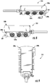
- the device 310 is similar to the device 210 shown in Figures 5 and 6 , but includes two canopies 328a, 328b that extend from opposite ends of the arced wall 320 to overhang respective side walls 322, 324.
- Three mixed media connectors 334a, 334b are mounted on both side walls 333, 324 in the illustrated embodiment such that the canopies 328a, 328b can protect them during installation.
- Additional canopies e..g, extending perpendicularly from the floor
- each of the canopies 328a, 328b includes a respective slot 329 as a fastening feature.
- the slots 329 can receive a wire or string (not shown) routed therethrough that can be employed to hoist the device 310 upwardly during installation. The presence of two slots 329 can enable the device 310 to remain upright as it is hoisted.
- the slots 329 may be omitted and the device hoisted by routing a rope or string under both of the canopies 328a, 328b to maintain the device in an upright orientation.
- the device 310 may include a power connector and a fiber optic connector (such as those shown at 28 and 30 in Figures 1 and 2 ) rather than the gland 230.
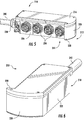
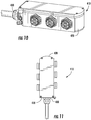
- FIG. 10 another device, designated broadly at 410, is shown therein.
- the device 410 is very similar to the device 310 with the exception that the there are no canopies included in the arced wall 420.
- the presence of the arced wall 420 opposite the entry point of the gland 430 in the end wall 418 can facilitate hoisting of the device 410 through cables and other structures.
Landscapes
- Physics & Mathematics (AREA)
- General Physics & Mathematics (AREA)
- Optics & Photonics (AREA)
- Light Guides In General And Applications Therefor (AREA)
- Cable Accessories (AREA)
- Coupling Device And Connection With Printed Circuit (AREA)
Claims (4)
- Vorrichtung (310) zum Verbinden eines Hybridstammkabels (240) mit einem oder mehreren Rangierkabeln, umfassend:ein Gehäuse (212) mit einer ersten und einer zweiten Endwand (218, 220), die einander entgegengesetzt sind, und einer ersten und einer zweiten Seitenwand (224, 222), die einander entgegengesetzt sind;ein Hybridkabel, das in die erste Endwand (218) eintritt, wobei das Hybridkabel einen oder mehrere Leiter und mehrere Lichtwellenleiter aufweist;erste mehrere Mischmedienverbinder (334b), die an der ersten Seitenwand angebracht sind; undzweite mehrere Mischmedienverbinder (334a), die an der zweiten Seitenwand angebracht sind,wobei der eine oder die mehreren Leiter des Hybridkabels mit den ersten und den zweiten mehreren Mischmedienverbindern (334b, 334a) elektrisch verbunden sind, und wobei jeder der mehreren Lichtwellenleiter mit entsprechenden der ersten und der zweiten mehreren Mischmedienverbinder optisch verbunden ist,dadurch gekennzeichnet, dassdie zweite Endwand (220) eine erste Überdachung (328b) umfasst, die über die erste Seitenwand (224) übersteht, unddie zweite Endwand ferner eine zweite Überdachung (328a) umfasst, die über die zweite Seitenwand (222) übersteht.
- Vorrichtung (310) nach Anspruch 1, wobei die erste und die zweite Seitenwand gerade Seitenwände sind.
- Vorrichtung (310) nach Anspruch 1, wobei jede von der ersten und der zweiten Überdachung (328b, 328a) ein Befestigungselement (329) aufweist.
- Vorrichtung (310) nach Anspruch 1, wobei die zweite Endwand bogenförmig ist.
Applications Claiming Priority (3)
| Application Number | Priority Date | Filing Date | Title |
|---|---|---|---|
| US201461936636P | 2014-02-06 | 2014-02-06 | |
| US14/448,269 US9606320B2 (en) | 2014-02-06 | 2014-07-31 | Device for distributing hybrid cable and transitioning from trunk cable to jumper cable |
| PCT/US2015/014347 WO2015119983A1 (en) | 2014-02-06 | 2015-02-04 | Device for distributing hybrid cable and transitioning from trunk cable to jumper cable |
Publications (3)
| Publication Number | Publication Date |
|---|---|
| EP3103165A1 EP3103165A1 (de) | 2016-12-14 |
| EP3103165A4 EP3103165A4 (de) | 2017-09-20 |
| EP3103165B1 true EP3103165B1 (de) | 2021-11-24 |
Family
ID=53754696
Family Applications (1)
| Application Number | Title | Priority Date | Filing Date |
|---|---|---|---|
| EP15746886.9A Not-in-force EP3103165B1 (de) | 2014-02-06 | 2015-02-04 | Vorrichtung zur verteilung eines hybridkabels und für übergang von stammkabel zu überbrückungskabel |
Country Status (5)
| Country | Link |
|---|---|
| US (2) | US9606320B2 (de) |
| EP (1) | EP3103165B1 (de) |
| CN (1) | CN105900295B (de) |
| AU (1) | AU2015214352B2 (de) |
| WO (1) | WO2015119983A1 (de) |
Families Citing this family (32)
| Publication number | Priority date | Publication date | Assignee | Title |
|---|---|---|---|---|
| US9784937B2 (en) * | 2013-02-01 | 2017-10-10 | Ccs Technology, Inc. | Cable assembly having electrical power conductors and fiber optic data lines |
| US9606320B2 (en) * | 2014-02-06 | 2017-03-28 | Commscope Technologies Llc | Device for distributing hybrid cable and transitioning from trunk cable to jumper cable |
| US9448365B2 (en) * | 2014-12-31 | 2016-09-20 | Commscope, Inc. Of North Carolina | Trunk gland adapters and related trunk gland units and methods of connecting trunk cables to fiber optic enclosures |
| MX383784B (es) | 2015-01-12 | 2025-03-14 | Afl Telecommunications Llc | Alojamiento de terminal de fibra optica. |
| WO2016149337A1 (en) | 2015-03-16 | 2016-09-22 | Commscope Technologies Llc | Enclosure for cable distribution assembly |
| US10424905B2 (en) * | 2015-06-10 | 2019-09-24 | Thomas & Betts International Llc | Shallow octagonal electrical box |
| WO2017027443A1 (en) * | 2015-08-10 | 2017-02-16 | Commscope Technologies Llc | Device for distributing hybrid cable and transitioning from trunk cable to jumper cable |
| AU2016317828B2 (en) * | 2015-09-04 | 2021-02-25 | Commscope Technologies Llc. | Device for distributing hybrid trunk cable |
| US10247899B2 (en) | 2015-09-04 | 2019-04-02 | Commscope Technologies Llc | Device for distributing hybrid trunk cable |
| US10520692B2 (en) | 2015-11-11 | 2019-12-31 | Afl Telecommunications Llc | Optical connection terminals for fiber optic communications networks |
| WO2017120059A1 (en) | 2016-01-07 | 2017-07-13 | Commscope Technologies Llc | Flexible device for distributing hybrid cable and transitioning from trunk cable to jumper cable |
| USD825471S1 (en) | 2016-03-16 | 2018-08-14 | Commscope Technologies Llc | Cable breakout enclosure design |
| USD876364S1 (en) * | 2016-03-16 | 2020-02-25 | Commscope Technologies Llc | Cable breakout enclosure |
| US10164389B2 (en) | 2016-09-26 | 2018-12-25 | Commscope Technologies Llc | Breakout enclosure for transitioning from trunk cable to jumper cable |
| US20220132229A1 (en) * | 2016-10-10 | 2022-04-28 | Telescent, Inc. | Incrementally scalable, two-tier system of robotic, fiber optic interconnect units enabling any-to-any connectivity |
| US10355423B2 (en) | 2016-10-24 | 2019-07-16 | Commscope Technologies Llc | Hybrid connector assembly with integrated overvoltage protection |
| CN108152898A (zh) * | 2016-12-06 | 2018-06-12 | 上海贝尔股份有限公司 | 一种光电混合分线盒、光电混合连接系统以及连接方法 |
| US11417943B2 (en) * | 2017-03-06 | 2022-08-16 | Commscope Technologies Llc | Modular monopole for wireless communications |
| US10209475B2 (en) | 2017-03-21 | 2019-02-19 | Commscope Technologies Llc | Modular breakout enclosure for transitioning from trunk cable to jumper cable |
| US9977211B1 (en) | 2017-04-21 | 2018-05-22 | Afl Telecommunications Llc | Optical connection terminals for fiber optic communications networks |
| US10985454B2 (en) * | 2017-06-15 | 2021-04-20 | Commscope Technologies Llc | Base station antennas having bottom end caps with angled connector ports |
| US10502915B2 (en) | 2017-06-29 | 2019-12-10 | Commscope Technologies Llc | Device for distributing trunk cable to jumper cable |
| USD840342S1 (en) * | 2017-07-31 | 2019-02-12 | Tectonica Australia Pty Ltd | Cabling hub |
| NZ764014A (en) * | 2017-11-24 | 2023-07-28 | Prysmian Spa | Electrical power and optical distribution box for fiber to the antenna systems |
| US11874517B2 (en) | 2018-10-19 | 2024-01-16 | Commscope Technologies Llc | Telecommunications terminal with stub cable |
| US12003016B2 (en) * | 2018-10-29 | 2024-06-04 | Commscope Technologies Llc | Perforated door for monopole module and method of mounting same |
| USD901391S1 (en) | 2019-02-19 | 2020-11-10 | North American Interconnect L.L.C. | Distribution housing |
| KR102706689B1 (ko) * | 2019-05-23 | 2024-09-12 | 엘에스전선 주식회사 | 광전복합 케이블용 터미널박스 및 광전복합 터미널박스 시스템 |
| CN110854597B (zh) * | 2019-10-30 | 2021-07-16 | 深圳供电局有限公司 | 组合式电缆接头 |
| GB201917658D0 (en) * | 2019-12-03 | 2020-01-15 | Hughes Electronics Ltd | Cable distribution box |
| CN111799582B (zh) * | 2020-05-19 | 2021-09-14 | 华为技术有限公司 | 一种接线端子及传输设备 |
| WO2022119632A1 (en) | 2020-12-02 | 2022-06-09 | Commscope Technologies Llc | Ganged coaxial connector assembly with removable connector-cable configuration |
Family Cites Families (14)
| Publication number | Priority date | Publication date | Assignee | Title |
|---|---|---|---|---|
| WO2003019243A2 (en) * | 2001-05-21 | 2003-03-06 | Wave7 Optics, Inc. | Cable splice enclosure and components |
| US7489849B2 (en) * | 2004-11-03 | 2009-02-10 | Adc Telecommunications, Inc. | Fiber drop terminal |
| CN101943781A (zh) * | 2004-11-03 | 2011-01-12 | Adc电信公司 | 光纤投落终端 |
| US8401387B2 (en) | 2007-08-30 | 2013-03-19 | Calix, Inc. | Optical network interface devices and methods |
| CA2621016C (en) | 2008-02-13 | 2016-09-13 | Fiber Connections Inc. | Digital signal media conversion panel |
| US20110097052A1 (en) * | 2009-10-21 | 2011-04-28 | Solheid James J | Fiber Access Terminal Mounted at a Mid-Span Access Location of a Telecommunications Cable |
| CN102948092A (zh) | 2010-06-23 | 2013-02-27 | 3M创新有限公司 | 室内无线网络应用的混合布线系统和网络 |
| US20120008257A1 (en) * | 2010-07-06 | 2012-01-12 | 3M Innovative Properties Company | Cell tower wiring junction box |
| DE202011110642U1 (de) * | 2010-09-21 | 2016-03-17 | Huber + Suhner Ag | Umwelttauglich abgedichtete Kabelpeitschen-Anordnungen |
| PL2710691T3 (pl) | 2011-05-17 | 2017-01-31 | 3M Innovative Properties Company | Urządzenie z gniazdem zdalnym |
| CN104041066A (zh) * | 2011-10-03 | 2014-09-10 | 蒂科电子瑞侃有限公司 | 用于户外高架场所的集线箱 |
| US9069151B2 (en) | 2011-10-26 | 2015-06-30 | Corning Cable Systems Llc | Composite cable breakout assembly |
| US8842954B2 (en) * | 2012-05-02 | 2014-09-23 | Corning Cable Systems Llc | Cable assembly |
| US9606320B2 (en) * | 2014-02-06 | 2017-03-28 | Commscope Technologies Llc | Device for distributing hybrid cable and transitioning from trunk cable to jumper cable |
-
2014
- 2014-07-31 US US14/448,269 patent/US9606320B2/en active Active
-
2015
- 2015-02-04 CN CN201580004294.8A patent/CN105900295B/zh not_active Expired - Fee Related
- 2015-02-04 EP EP15746886.9A patent/EP3103165B1/de not_active Not-in-force
- 2015-02-04 WO PCT/US2015/014347 patent/WO2015119983A1/en not_active Ceased
- 2015-02-04 AU AU2015214352A patent/AU2015214352B2/en not_active Ceased
-
2017
- 2017-02-15 US US15/433,436 patent/US9857537B2/en not_active Expired - Fee Related
Non-Patent Citations (1)
| Title |
|---|
| None * |
Also Published As
| Publication number | Publication date |
|---|---|
| AU2015214352A1 (en) | 2016-07-14 |
| CN105900295B (zh) | 2019-07-16 |
| CN105900295A (zh) | 2016-08-24 |
| US20150219856A1 (en) | 2015-08-06 |
| EP3103165A4 (de) | 2017-09-20 |
| US20170160489A1 (en) | 2017-06-08 |
| AU2015214352B2 (en) | 2018-09-13 |
| US9857537B2 (en) | 2018-01-02 |
| US9606320B2 (en) | 2017-03-28 |
| EP3103165A1 (de) | 2016-12-14 |
| WO2015119983A1 (en) | 2015-08-13 |
Similar Documents
| Publication | Publication Date | Title |
|---|---|---|
| EP3103165B1 (de) | Vorrichtung zur verteilung eines hybridkabels und für übergang von stammkabel zu überbrückungskabel | |
| US9535226B2 (en) | Modular breakout device for optical and electrical connections | |
| CN104081237B (zh) | 复合电缆分支总成 | |
| US9548603B2 (en) | Environmentally sealed cable breakout assemblies | |
| US10393976B2 (en) | Device for distributing hybrid cable and transitioning from trunk cable to jumper cable with overvoltage protection | |
| US8472767B2 (en) | Fiber optic cable and fiber optic cable assembly for wireless access | |
| US10164389B2 (en) | Breakout enclosure for transitioning from trunk cable to jumper cable | |
| US10209475B2 (en) | Modular breakout enclosure for transitioning from trunk cable to jumper cable | |
| CN105093451B (zh) | 一种分纤及配电装置及通信站点 | |
| EP3714300B1 (de) | Elektrischer energie- und optischer verteilerkasten für die faser zu den antennensystemen | |
| US9869822B2 (en) | Device for distributing hybrid cable and transitioning from trunk cable to jumper cable | |
| US10234634B2 (en) | Flexible device for distributing hybrid cable and transitioning from trunk cable to jumper cable | |
| KR200472023Y1 (ko) | 커넥터형 접속함체 | |
| CN204855902U (zh) | 一种分纤及配电装置及通信站点 | |
| US20160363731A1 (en) | Device for transitioning from trunk cable to jumper cable | |
| CN202474795U (zh) | 光电复合缆的转接盒 | |
| WO2017103342A1 (en) | Cable divider and cable arrangement | |
| WO2015192294A1 (zh) | 外接模块 |
Legal Events
| Date | Code | Title | Description |
|---|---|---|---|
| PUAI | Public reference made under article 153(3) epc to a published international application that has entered the european phase |
Free format text: ORIGINAL CODE: 0009012 |
|
| STAA | Information on the status of an ep patent application or granted ep patent |
Free format text: STATUS: REQUEST FOR EXAMINATION WAS MADE |
|
| 17P | Request for examination filed |
Effective date: 20160628 |
|
| AK | Designated contracting states |
Kind code of ref document: A1 Designated state(s): AL AT BE BG CH CY CZ DE DK EE ES FI FR GB GR HR HU IE IS IT LI LT LU LV MC MK MT NL NO PL PT RO RS SE SI SK SM TR |
|
| AX | Request for extension of the european patent |
Extension state: BA ME |
|
| DAX | Request for extension of the european patent (deleted) | ||
| A4 | Supplementary search report drawn up and despatched |
Effective date: 20170822 |
|
| RIC1 | Information provided on ipc code assigned before grant |
Ipc: G02B 6/44 20060101AFI20170816BHEP Ipc: G02B 6/38 20060101ALI20170816BHEP Ipc: H01R 31/02 20060101ALI20170816BHEP |
|
| STAA | Information on the status of an ep patent application or granted ep patent |
Free format text: STATUS: EXAMINATION IS IN PROGRESS |
|
| 17Q | First examination report despatched |
Effective date: 20200320 |
|
| REG | Reference to a national code |
Ref country code: DE Ref legal event code: R079 Ref document number: 602015075232 Country of ref document: DE Free format text: PREVIOUS MAIN CLASS: H01R0031060000 Ipc: G02B0006440000 |
|
| GRAP | Despatch of communication of intention to grant a patent |
Free format text: ORIGINAL CODE: EPIDOSNIGR1 |
|
| STAA | Information on the status of an ep patent application or granted ep patent |
Free format text: STATUS: GRANT OF PATENT IS INTENDED |
|
| RIC1 | Information provided on ipc code assigned before grant |
Ipc: G02B 6/44 20060101AFI20210526BHEP Ipc: H01R 31/02 20060101ALI20210526BHEP Ipc: G02B 6/38 20060101ALI20210526BHEP Ipc: H02G 3/08 20060101ALI20210526BHEP |
|
| INTG | Intention to grant announced |
Effective date: 20210624 |
|
| GRAA | (expected) grant |
Free format text: ORIGINAL CODE: 0009210 |
|
| STAA | Information on the status of an ep patent application or granted ep patent |
Free format text: STATUS: THE PATENT HAS BEEN GRANTED |
|
| GRAS | Grant fee paid |
Free format text: ORIGINAL CODE: EPIDOSNIGR3 |
|
| AK | Designated contracting states |
Kind code of ref document: B1 Designated state(s): AL AT BE BG CH CY CZ DE DK EE ES FI FR GB GR HR HU IE IS IT LI LT LU LV MC MK MT NL NO PL PT RO RS SE SI SK SM TR |
|
| REG | Reference to a national code |
Ref country code: GB Ref legal event code: FG4D |
|
| RIN1 | Information on inventor provided before grant (corrected) |
Inventor name: WANG, CHI-MING |
|
| REG | Reference to a national code |
Ref country code: DE Ref legal event code: R096 Ref document number: 602015075232 Country of ref document: DE |
|
| REG | Reference to a national code |
Ref country code: AT Ref legal event code: REF Ref document number: 1450289 Country of ref document: AT Kind code of ref document: T Effective date: 20211215 |
|
| REG | Reference to a national code |
Ref country code: IE Ref legal event code: FG4D |
|
| REG | Reference to a national code |
Ref country code: LT Ref legal event code: MG9D |
|
| REG | Reference to a national code |
Ref country code: NL Ref legal event code: MP Effective date: 20211124 |
|
| REG | Reference to a national code |
Ref country code: AT Ref legal event code: MK05 Ref document number: 1450289 Country of ref document: AT Kind code of ref document: T Effective date: 20211124 |
|
| PG25 | Lapsed in a contracting state [announced via postgrant information from national office to epo] |
Ref country code: RS Free format text: LAPSE BECAUSE OF FAILURE TO SUBMIT A TRANSLATION OF THE DESCRIPTION OR TO PAY THE FEE WITHIN THE PRESCRIBED TIME-LIMIT Effective date: 20211124 Ref country code: LT Free format text: LAPSE BECAUSE OF FAILURE TO SUBMIT A TRANSLATION OF THE DESCRIPTION OR TO PAY THE FEE WITHIN THE PRESCRIBED TIME-LIMIT Effective date: 20211124 Ref country code: FI Free format text: LAPSE BECAUSE OF FAILURE TO SUBMIT A TRANSLATION OF THE DESCRIPTION OR TO PAY THE FEE WITHIN THE PRESCRIBED TIME-LIMIT Effective date: 20211124 Ref country code: BG Free format text: LAPSE BECAUSE OF FAILURE TO SUBMIT A TRANSLATION OF THE DESCRIPTION OR TO PAY THE FEE WITHIN THE PRESCRIBED TIME-LIMIT Effective date: 20220224 Ref country code: AT Free format text: LAPSE BECAUSE OF FAILURE TO SUBMIT A TRANSLATION OF THE DESCRIPTION OR TO PAY THE FEE WITHIN THE PRESCRIBED TIME-LIMIT Effective date: 20211124 |
|
| PG25 | Lapsed in a contracting state [announced via postgrant information from national office to epo] |
Ref country code: IS Free format text: LAPSE BECAUSE OF FAILURE TO SUBMIT A TRANSLATION OF THE DESCRIPTION OR TO PAY THE FEE WITHIN THE PRESCRIBED TIME-LIMIT Effective date: 20220324 Ref country code: SE Free format text: LAPSE BECAUSE OF FAILURE TO SUBMIT A TRANSLATION OF THE DESCRIPTION OR TO PAY THE FEE WITHIN THE PRESCRIBED TIME-LIMIT Effective date: 20211124 Ref country code: PT Free format text: LAPSE BECAUSE OF FAILURE TO SUBMIT A TRANSLATION OF THE DESCRIPTION OR TO PAY THE FEE WITHIN THE PRESCRIBED TIME-LIMIT Effective date: 20220324 Ref country code: PL Free format text: LAPSE BECAUSE OF FAILURE TO SUBMIT A TRANSLATION OF THE DESCRIPTION OR TO PAY THE FEE WITHIN THE PRESCRIBED TIME-LIMIT Effective date: 20211124 Ref country code: NO Free format text: LAPSE BECAUSE OF FAILURE TO SUBMIT A TRANSLATION OF THE DESCRIPTION OR TO PAY THE FEE WITHIN THE PRESCRIBED TIME-LIMIT Effective date: 20220224 Ref country code: NL Free format text: LAPSE BECAUSE OF FAILURE TO SUBMIT A TRANSLATION OF THE DESCRIPTION OR TO PAY THE FEE WITHIN THE PRESCRIBED TIME-LIMIT Effective date: 20211124 Ref country code: LV Free format text: LAPSE BECAUSE OF FAILURE TO SUBMIT A TRANSLATION OF THE DESCRIPTION OR TO PAY THE FEE WITHIN THE PRESCRIBED TIME-LIMIT Effective date: 20211124 Ref country code: HR Free format text: LAPSE BECAUSE OF FAILURE TO SUBMIT A TRANSLATION OF THE DESCRIPTION OR TO PAY THE FEE WITHIN THE PRESCRIBED TIME-LIMIT Effective date: 20211124 Ref country code: GR Free format text: LAPSE BECAUSE OF FAILURE TO SUBMIT A TRANSLATION OF THE DESCRIPTION OR TO PAY THE FEE WITHIN THE PRESCRIBED TIME-LIMIT Effective date: 20220225 Ref country code: ES Free format text: LAPSE BECAUSE OF FAILURE TO SUBMIT A TRANSLATION OF THE DESCRIPTION OR TO PAY THE FEE WITHIN THE PRESCRIBED TIME-LIMIT Effective date: 20211124 |
|
| PG25 | Lapsed in a contracting state [announced via postgrant information from national office to epo] |
Ref country code: SM Free format text: LAPSE BECAUSE OF FAILURE TO SUBMIT A TRANSLATION OF THE DESCRIPTION OR TO PAY THE FEE WITHIN THE PRESCRIBED TIME-LIMIT Effective date: 20211124 Ref country code: SK Free format text: LAPSE BECAUSE OF FAILURE TO SUBMIT A TRANSLATION OF THE DESCRIPTION OR TO PAY THE FEE WITHIN THE PRESCRIBED TIME-LIMIT Effective date: 20211124 Ref country code: RO Free format text: LAPSE BECAUSE OF FAILURE TO SUBMIT A TRANSLATION OF THE DESCRIPTION OR TO PAY THE FEE WITHIN THE PRESCRIBED TIME-LIMIT Effective date: 20211124 Ref country code: EE Free format text: LAPSE BECAUSE OF FAILURE TO SUBMIT A TRANSLATION OF THE DESCRIPTION OR TO PAY THE FEE WITHIN THE PRESCRIBED TIME-LIMIT Effective date: 20211124 Ref country code: DK Free format text: LAPSE BECAUSE OF FAILURE TO SUBMIT A TRANSLATION OF THE DESCRIPTION OR TO PAY THE FEE WITHIN THE PRESCRIBED TIME-LIMIT Effective date: 20211124 Ref country code: CZ Free format text: LAPSE BECAUSE OF FAILURE TO SUBMIT A TRANSLATION OF THE DESCRIPTION OR TO PAY THE FEE WITHIN THE PRESCRIBED TIME-LIMIT Effective date: 20211124 |
|
| REG | Reference to a national code |
Ref country code: DE Ref legal event code: R097 Ref document number: 602015075232 Country of ref document: DE |
|
| REG | Reference to a national code |
Ref country code: DE Ref legal event code: R119 Ref document number: 602015075232 Country of ref document: DE |
|
| PG25 | Lapsed in a contracting state [announced via postgrant information from national office to epo] |
Ref country code: MC Free format text: LAPSE BECAUSE OF FAILURE TO SUBMIT A TRANSLATION OF THE DESCRIPTION OR TO PAY THE FEE WITHIN THE PRESCRIBED TIME-LIMIT Effective date: 20211124 |
|
| PLBE | No opposition filed within time limit |
Free format text: ORIGINAL CODE: 0009261 |
|
| STAA | Information on the status of an ep patent application or granted ep patent |
Free format text: STATUS: NO OPPOSITION FILED WITHIN TIME LIMIT |
|
| REG | Reference to a national code |
Ref country code: CH Ref legal event code: PL |
|
| REG | Reference to a national code |
Ref country code: BE Ref legal event code: MM Effective date: 20220228 |
|
| GBPC | Gb: european patent ceased through non-payment of renewal fee |
Effective date: 20220224 |
|
| PG25 | Lapsed in a contracting state [announced via postgrant information from national office to epo] |
Ref country code: LU Free format text: LAPSE BECAUSE OF NON-PAYMENT OF DUE FEES Effective date: 20220204 Ref country code: AL Free format text: LAPSE BECAUSE OF FAILURE TO SUBMIT A TRANSLATION OF THE DESCRIPTION OR TO PAY THE FEE WITHIN THE PRESCRIBED TIME-LIMIT Effective date: 20211124 |
|
| 26N | No opposition filed |
Effective date: 20220825 |
|
| PG25 | Lapsed in a contracting state [announced via postgrant information from national office to epo] |
Ref country code: SI Free format text: LAPSE BECAUSE OF FAILURE TO SUBMIT A TRANSLATION OF THE DESCRIPTION OR TO PAY THE FEE WITHIN THE PRESCRIBED TIME-LIMIT Effective date: 20211124 |
|
| PG25 | Lapsed in a contracting state [announced via postgrant information from national office to epo] |
Ref country code: FR Free format text: LAPSE BECAUSE OF NON-PAYMENT OF DUE FEES Effective date: 20220228 |
|
| PG25 | Lapsed in a contracting state [announced via postgrant information from national office to epo] |
Ref country code: LI Free format text: LAPSE BECAUSE OF NON-PAYMENT OF DUE FEES Effective date: 20220228 Ref country code: IE Free format text: LAPSE BECAUSE OF NON-PAYMENT OF DUE FEES Effective date: 20220204 Ref country code: GB Free format text: LAPSE BECAUSE OF NON-PAYMENT OF DUE FEES Effective date: 20220224 Ref country code: DE Free format text: LAPSE BECAUSE OF NON-PAYMENT OF DUE FEES Effective date: 20220901 Ref country code: CH Free format text: LAPSE BECAUSE OF NON-PAYMENT OF DUE FEES Effective date: 20220228 |
|
| PG25 | Lapsed in a contracting state [announced via postgrant information from national office to epo] |
Ref country code: BE Free format text: LAPSE BECAUSE OF NON-PAYMENT OF DUE FEES Effective date: 20220228 |
|
| PG25 | Lapsed in a contracting state [announced via postgrant information from national office to epo] |
Ref country code: IT Free format text: LAPSE BECAUSE OF FAILURE TO SUBMIT A TRANSLATION OF THE DESCRIPTION OR TO PAY THE FEE WITHIN THE PRESCRIBED TIME-LIMIT Effective date: 20211124 |
|
| PG25 | Lapsed in a contracting state [announced via postgrant information from national office to epo] |
Ref country code: HU Free format text: LAPSE BECAUSE OF FAILURE TO SUBMIT A TRANSLATION OF THE DESCRIPTION OR TO PAY THE FEE WITHIN THE PRESCRIBED TIME-LIMIT; INVALID AB INITIO Effective date: 20150204 |
|
| PG25 | Lapsed in a contracting state [announced via postgrant information from national office to epo] |
Ref country code: MK Free format text: LAPSE BECAUSE OF FAILURE TO SUBMIT A TRANSLATION OF THE DESCRIPTION OR TO PAY THE FEE WITHIN THE PRESCRIBED TIME-LIMIT Effective date: 20211124 Ref country code: CY Free format text: LAPSE BECAUSE OF FAILURE TO SUBMIT A TRANSLATION OF THE DESCRIPTION OR TO PAY THE FEE WITHIN THE PRESCRIBED TIME-LIMIT Effective date: 20211124 |
|
| PG25 | Lapsed in a contracting state [announced via postgrant information from national office to epo] |
Ref country code: TR Free format text: LAPSE BECAUSE OF FAILURE TO SUBMIT A TRANSLATION OF THE DESCRIPTION OR TO PAY THE FEE WITHIN THE PRESCRIBED TIME-LIMIT Effective date: 20211124 |
|
| PG25 | Lapsed in a contracting state [announced via postgrant information from national office to epo] |
Ref country code: MT Free format text: LAPSE BECAUSE OF FAILURE TO SUBMIT A TRANSLATION OF THE DESCRIPTION OR TO PAY THE FEE WITHIN THE PRESCRIBED TIME-LIMIT Effective date: 20211124 |